WO2019013263A1 - Plaquette de coupe, outil de coupe et procédé de fabrication de pièce coupée - Google Patents
Plaquette de coupe, outil de coupe et procédé de fabrication de pièce coupée Download PDFInfo
- Publication number
- WO2019013263A1 WO2019013263A1 PCT/JP2018/026220 JP2018026220W WO2019013263A1 WO 2019013263 A1 WO2019013263 A1 WO 2019013263A1 JP 2018026220 W JP2018026220 W JP 2018026220W WO 2019013263 A1 WO2019013263 A1 WO 2019013263A1
- Authority
- WO
- WIPO (PCT)
- Prior art keywords
- hole
- insert
- recess
- straight line
- cutting
- Prior art date
- Legal status (The legal status is an assumption and is not a legal conclusion. Google has not performed a legal analysis and makes no representation as to the accuracy of the status listed.)
- Ceased
Links
Images








Classifications
-
- B—PERFORMING OPERATIONS; TRANSPORTING
- B23—MACHINE TOOLS; METAL-WORKING NOT OTHERWISE PROVIDED FOR
- B23B—TURNING; BORING
- B23B27/00—Tools for turning or boring machines; Tools of a similar kind in general; Accessories therefor
- B23B27/007—Tools for turning or boring machines; Tools of a similar kind in general; Accessories therefor for internal turning
-
- B—PERFORMING OPERATIONS; TRANSPORTING
- B23—MACHINE TOOLS; METAL-WORKING NOT OTHERWISE PROVIDED FOR
- B23B—TURNING; BORING
- B23B27/00—Tools for turning or boring machines; Tools of a similar kind in general; Accessories therefor
- B23B27/14—Cutting tools of which the bits or tips or cutting inserts are of special material
- B23B27/16—Cutting tools of which the bits or tips or cutting inserts are of special material with exchangeable cutting bits or cutting inserts, e.g. able to be clamped
- B23B27/1603—Cutting tools of which the bits or tips or cutting inserts are of special material with exchangeable cutting bits or cutting inserts, e.g. able to be clamped with specially shaped plate-like exchangeable cutting inserts, e.g. chip-breaking groove
- B23B27/1611—Cutting tools of which the bits or tips or cutting inserts are of special material with exchangeable cutting bits or cutting inserts, e.g. able to be clamped with specially shaped plate-like exchangeable cutting inserts, e.g. chip-breaking groove characterised by having a special shape
-
- B—PERFORMING OPERATIONS; TRANSPORTING
- B23—MACHINE TOOLS; METAL-WORKING NOT OTHERWISE PROVIDED FOR
- B23B—TURNING; BORING
- B23B1/00—Methods for turning or working essentially requiring the use of turning-machines; Use of auxiliary equipment in connection with such methods
-
- B—PERFORMING OPERATIONS; TRANSPORTING
- B23—MACHINE TOOLS; METAL-WORKING NOT OTHERWISE PROVIDED FOR
- B23B—TURNING; BORING
- B23B27/00—Tools for turning or boring machines; Tools of a similar kind in general; Accessories therefor
- B23B27/04—Cutting-off tools
-
- B—PERFORMING OPERATIONS; TRANSPORTING
- B23—MACHINE TOOLS; METAL-WORKING NOT OTHERWISE PROVIDED FOR
- B23B—TURNING; BORING
- B23B29/00—Holders for non-rotary cutting tools; Boring bars or boring heads; Accessories for tool holders
- B23B29/04—Tool holders for a single cutting tool
- B23B29/043—Tool holders for a single cutting tool with cutting-off, grooving or profile cutting tools, i.e. blade- or disc-like main cutting parts
-
- B—PERFORMING OPERATIONS; TRANSPORTING
- B23—MACHINE TOOLS; METAL-WORKING NOT OTHERWISE PROVIDED FOR
- B23B—TURNING; BORING
- B23B2220/00—Details of turning, boring or drilling processes
- B23B2220/12—Grooving
- B23B2220/123—Producing internal grooves
-
- B—PERFORMING OPERATIONS; TRANSPORTING
- B23—MACHINE TOOLS; METAL-WORKING NOT OTHERWISE PROVIDED FOR
- B23B—TURNING; BORING
- B23B2220/00—Details of turning, boring or drilling processes
- B23B2220/12—Grooving
- B23B2220/126—Producing ring grooves
Definitions
- the present aspect generally relates to a cutting insert, a cutting tool, and a method of manufacturing a machined product. More specifically, the present invention relates to a cutting tool used for grooving.
- Patent Document 1 As a cutting tool used when cutting a work material, for example, a cutting tool described in Japanese Patent Application Publication No. 2014-504561 (Patent Document 1) is known.
- the insert in the cutting tool described in Patent Document 1 has a recess located on the upper surface side.
- the holder in the cutting tool of patent document 1 has the convex part corresponding to said recessed part.
- One insert of the aspect has a first surface, a second surface located on the opposite side of the first surface, a side surface located between the first surface and the second surface, and a first one of the side surfaces.
- a main body having a first cutting edge located at least a part of a ridge line where a side surface and a second side surface adjacent to the first side intersect and a through hole opening at the first surface and the second surface There is.
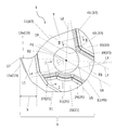
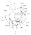
- the body further includes a first recess extending from the first surface to the side surface. The first recess is located apart from a virtual straight line connecting the first cutting edge and the center of the through hole when the first surface is viewed from the front.
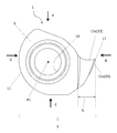
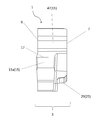
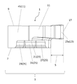
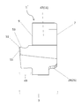
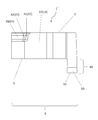
- FIG. 3 is a cross-sectional view showing a cross section II in FIG. 2; It is the side view which looked at the cutting insert shown in FIG. 3 from the D direction.
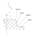
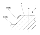
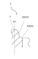
- FIG. 3 is a cross-sectional view showing a II-II cross section in FIG. 2; It is a top view of the modification of the cutting insert shown in FIG. 11 is a cross-sectional view showing a III-III cross section in FIG. 11 is a cross-sectional view showing a IV-IV cross section in FIG.
- FIG. 24 is an enlarged view of a part of the side of the first end of the holder shown in FIG. 23; It is the top view which looked at the holder shown in FIG. 23 toward the 1st end.
- 26 is a cross-sectional view showing a IV-IV cross section in FIG. 25. It is the figure which showed 1 process in the manufacturing method of the cutting material of embodiment. It is the figure which showed 1 process in the manufacturing method of the cutting material of embodiment. It is the figure which showed 1 process in the manufacturing method of the cutting material of embodiment.
- cutting inserts 1 (hereinafter, also simply referred to as inserts 1) according to a plurality of embodiments will be described in detail with reference to the drawings.
- the drawings referred to in the following simply show only the main members necessary for describing each embodiment.
- the insert 1 of the present disclosure may comprise any component not shown in the figures to which it refers.
- the dimensions of the members in the respective drawings do not faithfully represent the dimensions of the actual constituent members, the dimensional ratio of the respective members, and the like.
- One insert 1 of the embodiment has a flat plate-shaped main body 3 as shown in FIG.
- the main body 3 has a first surface 7, a second surface 9 located on the opposite side of the first surface 7, and a side surface 11 located between the first surface 7 and the second surface 9.
- the first surface 7 and the second surface 9 may be parallel to each other.
- the side surface 11 has a first side surface 13 and a second side surface 15 adjacent to the first side surface 13 as shown in FIGS. 1 and 2.
- the first side 13 and the second side 15 may intersect.
- the main body 3 may have a first cutting edge 17 located at at least a part of a ridge line where the first side surface 13 and the second side surface 15 intersect.
- the first side surface 13 in the example shown in FIG. 2 extends from the first cutting edge 17 and has a concave shape.
- the second side surface 15 in the example shown in FIG. 2 extends from the first cutting edge 17 and has a planar shape.
- the first side surface 13 may have a rake surface area 13a as shown in FIG.
- the second side surface 15 may have a flank surface area 15a.
- the rake surface area 13a is an area that can contact chips and cause the chips to curl during cutting.
- the rake surface area 13 a is located on a portion of the first side surface 13 along the first cutting edge 17.
- the flank surface area 15a is an area which is escaped so as to reduce the contact with the finished surface of the work material at the time of cutting.
- the flank surface area 15 a is located on a portion of the second side surface 15 along the first cutting edge 17.
- the flank surface area 15a is not required to be in no contact with the finished surface at the time of cutting.
- the first cutting edge 17 may be located at only a part of the ridge line where the first side surface 13 and the second side surface 15 intersect, or may be located at the whole.
- a so-called honing process may be applied to the first cutting edge 17 located at a ridge line where the first side surface 13 and the second side surface 15 intersect. That is, the ridgeline which the 1st side 13 and the 2nd side 15 cross may not be a strict line shape by two sides crossing.
- the main body 3 has a through hole 19 opened at the first surface 7 and the second surface 9 as shown in FIG.
- the insert 1 in the example shown in FIG. 1 and the like has a cutting portion 5 constituted by a first side surface 13, a second side surface 15 and a first cutting edge 17.
- the cutting portion 5 may protrude in a direction away from the central axis P1 of the through hole 19. Therefore, the first cutting edge 17 may be located farthest from the central axis P1 of the through hole 19.
- the through hole 19 may be used as an insertion hole of the fixture when mounting the insert 1 to the holder.
- fasteners include screws, wedges and brazes.
- the main body 3 may have a flat plate shape as described above, and the outer diameters of the first surface 7 and the second surface 9 may be larger than the thickness of the main body 3.
- FIG. 1 is an example, and the shape of the main body 3 is not limited to the shape shown in FIG.
- the main body 3 of the embodiment has a first recess 21 extending from the first surface 7 to the side surface 11.
- the first recess 21 when the first surface 7 is viewed from the front, the first recess 21 is located apart from the virtual straight line L1.
- the virtual straight line L1 connects the first cutting edge 17 and the central axis P1 of the through hole 19.
- the central axis P1 may be orthogonal to the first surface 7 and the second surface 9. In this case, when the first surface 7 is viewed from the front as shown in FIG. 2, the central axis P1 is indicated by a point.
- the virtual straight line L1 is located in a region where load is likely to be applied during cutting.
- the first recess 21 is located apart from the virtual straight line L1 connecting the first cutting edge 17 and the central axis P1 of the through hole 19, the thickness of the main body 3 in the region where load is likely to be applied during cutting Is easy to secure. Therefore, the durability of the insert 1 is high while the insert 1 is stably fixed to the holder by the first recess 21.
- the first side surface 13 may have a rake surface area 13a
- the second side surface 15 may have a flank surface area 15a.
- the first recess 21 is located not on the side of the first side 13 (upper side in FIG. 2) but on the side of the second side 15 (lower side in FIG. 2) with respect to the imaginary straight line L1. doing.
- the first recess 21 may be in contact with or separated from the through hole 19, but as in the example shown in FIG. 2, the first recess 21 may be separated from the through hole 19. Since the insert 1 is fixed to the holder by the fixing tool, a load is easily applied around the through hole 19 in the main body 3. When the first recess 21 is separated from the through hole 19, the thickness around the through hole 19 to which load is easily applied is secured. Therefore, the occurrence of a crack around the through hole 19 is suppressed.
- the first recess 21 may have a first bottom surface 23 and a first wall surface 25 located between the first bottom surface 23 and the first surface 7.
- the first bottom surface 23 is positioned substantially orthogonal to the central axis P1.
- the first wall surface 25 is positioned to be substantially orthogonal to the first bottom surface 23.
- generally orthogonal is a concept that is not limited to the configuration that is strictly orthogonal but allows a range of about 80 to 100 °.
- the first bottom surface 23 may be a concave surface or a convex surface, or may be a surface parallel to the first surface 7 as in the example shown in FIG.
- the first wall surface 25 may have a third surface 27 and a fourth surface 29 which are positioned to sandwich the perpendicular L2.
- the perpendicular line L2 in the example shown in FIG. 2 is orthogonal to the imaginary straight line L1 and passes through the central axis P1 of the through hole 19.
- a surface located closer to the first cutting edge 17 than the perpendicular L2 is a third surface 27, and a surface located farther from the first cutting edge 17 than the perpendicular L2 is a fourth surface 29.
- the portion of the holder facing the third surface 27 tends to be closer to the first cutting edge 17 than the fixing tool. In this case, since the load applied to the fixture is reduced, it is possible to more stably fix the insert 1 at a portion of the holder facing the third surface 27.
- the first wall surface 25 has the fourth surface 29
- the first wall surface 25 can be easily positioned across the perpendicular L2. In this case, the load applied to the fixture can be further reduced, so that the insert 1 can be more stably fixed.
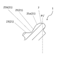
- the first wall surface 25 may be substantially parallel to the central axis P1 of the through hole 19 or may be inclined with respect to the central axis P1 of the through hole 19.
- an imaginary straight line which intersects the first surface 7 and is parallel to the central axis P1 of the through hole 19 is taken as an axis P1 '.
- the first wall 25 are compared. Note that the above-mentioned “parallel” does not have to be a positional relationship in which the two target parts are strictly parallel. Specifically, the two target parts may be inclined by about 5 ° or may be considered parallel.
- the insert 1 may have a connection surface 25 a connecting the first wall surface 25 and the first surface 7 and a connection surface 25 b connecting the first wall surface 25 and the first bottom surface 23.
- the angle between the extension of the virtual straight line L1 and the virtual extension L3 of the ridge line where the first surface 7 and the third surface 27 intersect is ⁇ 1. Further, when the first surface 7 is viewed from the front, an angle formed by an extension line of the virtual straight line L1 and the virtual straight line L4 is taken as ⁇ 2.
- the imaginary straight line L4 is a straight line connecting an end portion of the ridge line at which the first surface 7 and the third surface 27 intersect with each other and the central axis P1 at the most distant from the central axis P1.
- first wall surface 25 may further have a fifth surface 31 located between the third surface 27 and the fourth surface 29 when the first surface 7 is viewed from the front.
- the fifth surface 31 may be convex toward the outer peripheral side of the main body 3.
- the first recess 21 may be positioned along the through hole 19 so that the width between the first recess 21 and the through hole 19 is constant. In this case, the occurrence of a crack around the through hole 19 can be further suppressed.
- the fifth surface 31 may be concave with respect to the outer peripheral side of the main body 3 when the first surface 7 is viewed from the front.
- the fifth surface 31 has the above-described configuration, a large area of the first bottom surface 23 is easily secured. Therefore, the insert 1 is likely to be stably fixed to the holder.
- the main body 3 may have a second recess 33 located from the first surface 7 to the side surface 11.
- the second recess 33 may have a second bottom surface 35 and a second wall surface 37 located between the second bottom surface 35 and the first surface 7.
- the insert 1 can be stably fixed to the holder by bringing the second recess 33 in the insert 1 into contact with the holder.
- the second wall surface 37 may have a sixth surface 39, a seventh surface 41 and an eighth surface 43.
- the sixth surface 39 and the seventh surface 41 may have a flat surface shape.
- the eighth surface 43 is located between the sixth surface 39 and the seventh surface 41 and may be concave toward the outer peripheral side of the main body 3.
- the surface relatively near the first cutting edge 17 is the seventh surface 41.
- the surface located relatively away from the first cutting edge 17 is the sixth surface 39.
- the second bottom surface 35 may be parallel to the first surface 7.
- the sixth surface 39 and the seventh surface 41 of the second wall 37 may be parallel to the central axis P1.
- the sixth surface 39 and the seventh surface 41 of the second wall surface 37 may be parallel to the central axis P1 or may be inclined relative to the central axis P1.
- the sixth surface 39 in the example shown in FIGS. 10 to 12 is inclined so as to be closer to the axis P1 'as it goes from the side of the second bottom surface 35 to the side of the first surface 7.
- 10 to 12 show cross sections orthogonal to the first surface 7 and the sixth surface 39. As shown in FIG.
- the fourth surface 29 may be inclined so as to approach the axis P1 ′ as it goes from the side of the first bottom surface 23 to the side of the first surface 7.
- FIG. 12 shows a cross section orthogonal to the first surface 7 and the fourth surface 29.
- the inclination angle of the fourth surface 29 with respect to the axis P1 ' can be set to, for example, about 20 to 70 degrees.
- the insert 1 When the first surface 7 is viewed from the front, a force that tends to rotate in a counterclockwise direction with respect to the central axis P1 of the through hole 19 is applied to the main body 3 by the main component force applied at the time of cutting.
- the insert 1 can be held at the portion of the holder that faces the sixth surface 39.
- the insert 1 can be held at a portion facing the seventh surface 41 in the holder against a back force applied to the main body 3 at the time of cutting.
- the surface located away from the first cutting edge 17 may be the fourth surface 29.
- the sixth surface 39 may be a surface located away from the first cutting edge 17 among the sixth surface 39 and the seventh surface 41. At this time, when the first surface 7 is viewed from the front, the distance between the ridge line where the first surface 7 and the fourth surface 29 intersect and the ridge line where the first surface 7 and the sixth surface 39 intersect is the first cutting edge The distance from 17 may be wider.
- the ridge line where the first surface 7 and the fourth surface 29 intersect and the ridge line where the first surface 7 and the sixth surface 39 intersect may extend in a parallel direction.
- the bisector L6 of the angle formed by the virtual extension line L3 and the virtual extension line L5 is parallel to the ridge line where the first surface 7 and the fourth surface 29 intersect. It may be In addition, the bisector L6 may be parallel to the ridge line where the first surface 7 and the sixth surface 39 intersect.
- the virtual extension line L3 indicates a ridge line at which the first surface 7 and the third surface 27 intersect.
- the virtual extension line L5 indicates a ridge line at which the first surface 7 and the seventh surface 41 intersect.
- the bisector L6 described above does not have to be strictly parallel to the ridgeline where the first surface 7 and the fourth surface 29 intersect, and may be inclined at about -10 to 10 °. Similarly, the bisector L6 described above does not have to be strictly parallel to the ridgeline where the first surface 7 and the sixth surface 39 intersect, and may be inclined at about -10 to 10 °.
- the virtual extension line L3 and the virtual extension line L7 may intersect at the outside of the insert 1.
- the virtual extension line L7 indicates a ridge line at which the first surface 7 and the sixth surface 39 meet.
- the fourth surface 29 and the sixth surface 39 sandwich the fourth surface 29 and the sixth surface 39 in the direction perpendicular to the direction.
- the width of the covered surface is wide. Therefore, the thickness of the surface sandwiched by the fourth surface 29 and the sixth surface 39 can be easily secured, and the fracture resistance of the insert 1 is high.
- the side surface 11 may have a third side surface 45 and a fourth side surface 47.
- the third side surface 45 is located farther from the first cutting edge 17 than the perpendicular L ⁇ b> 2, and the radius of curvature may be constant.
- the fourth side surface 47 may be located between the third side surface 45 and the first side surface 13 and may be narrower than the third side surface 45 with respect to the through hole 19.
- the side surface 11 has the third side surface 45 and the fourth side surface 47
- chips generated by the first cutting edge 17 pass through the first side surface 13 having the rake surface area 13a to the fourth side surface 47. It may flow.
- the distance between the fourth side surface 47 and the through hole 19 is relatively narrow as described above, it is easy to secure a space for chips to flow on the fourth side surface 47. Therefore, the insert 1 satisfying such a configuration has high chip dischargeability.
- the size of the main body 3 is not particularly limited.
- the length from the central axis P1 to the first cutting edge 17 may be about 3 to 20 mm.
- the distance between the first surface 7 and the second surface 9 may be, for example, about 2 to 20 mm.
- Examples of the material of the insert 1 include cemented carbide and cermet.
- Examples of the composition of the cemented carbide include WC-Co, WC-TiC-Co, and WC-TiC-TaC-Co.
- WC-Co is produced by adding a powder of cobalt (Co) to tungsten carbide (WC) and sintering it.
- WC-TiC-Co is obtained by adding titanium carbide (TiC) to WC-Co.
- WC-TiC-TaC-Co is obtained by adding tantalum carbide (TaC) to WC-TiC-Co.
- cermet is a sintered composite material in which a ceramic component is compounded with a metal.
- a member containing a titanium compound such as titanium carbide (TiC) and titanium nitride (TiN) as a main component is mentioned.
- the surface of the insert 1 may be coated with a film using a chemical vapor deposition (CVD) method or a physical vapor deposition (PVD) method.
- the composition of the film may, for example, be titanium carbide (TiC), titanium nitride (TiN), titanium carbonitride (TiCN) or alumina (Al 2 O 3 ).
- insert 1 'of the embodiment will be described using the drawings.
- insert 1 'of this embodiment may have the same composition as insert 1, and explanation may be omitted about this same composition.
- Another insert 1 'of the embodiment has a generally flat body 3 as shown in FIG.
- the main body 3 has a first surface 7, a second surface 9 located on the opposite side of the first surface 7, and a side surface 11 located between the first surface 7 and the second surface 9.
- the main body 3 has a through hole 19 opened in the first surface 7 and the second surface 9.
- the main body 3 in the example shown in FIG. 13 has a protrusion 49 which is located on the second surface 9 and protrudes from the second surface 9 in a direction away from the first surface 7.
- the protrusion 49 is a portion corresponding to the cutting portion in the insert 1 described above.
- the protrusion 49 in the example shown in FIG. 13 protrudes in the direction along the central axis P1 of the through hole 19.
- the protrusion 49 has a second cutting edge 51 located at a position farthest from the first surface 7.
- a protrusion 49 extends from the second surface 9 and is adjacent to the first protrusion 53 having a rake surface area and the first protrusion 53 and located at the tip of the protrusion 49.
- a second projecting surface 55 having a flank surface area, and a second cutting edge 51 positioned at at least a part of a ridge line where the first projecting surface 53 and the second projecting surface 55 intersect.
- the insert 1 has the first cutting edge 17 located at at least a part of the ridge line where the first side surface 13 and the second side surface 15 intersect, while the insert 1 ′ has the first projecting surface 53.
- the 2nd cutting surface 51 has the 2nd cutting blade 51 located in at least one part of the ridgeline which meets.
- the main body 3 has a first recess 21 extending from the first surface 7 to the side surface 11.
- the first recess 21 in the example shown in FIG. 14 has a first bottom surface 23 and a first wall surface 25 located between the first bottom surface 23 and the first surface 7.
- the first recess 21 in the example shown in FIG. 14 is located apart from the virtual straight line L8 when the first surface 7 is seen through from the front.
- the virtual straight line L8 connects the center of the second cutting edge 51 and the central axis P1 of the through hole 19. Since the insert 1 ′ in the example shown in FIG. 14 has the above-described configuration, similarly to the insert 1, the durability on the imaginary straight line L ⁇ b> 8 to which a load is easily applied during cutting is high.
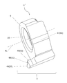
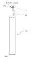
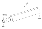
- the cutting tool 101 of the embodiment includes a holder 103 and an insert 1 represented by the above-described embodiment, as shown in FIG. In FIG. 18 to FIG. 22, the insert 1 is shown as a cutting insert.
- the cutting tool 101 may have an insert 1 'instead of the insert 1 without any problem.
- the holder 103 is a rod-like shape extending from the first end 103a (lower left end in FIG. 18) to the second end 103b (upper right end in FIG. 18), and has a pocket 105 on the side of the first end 103a.
- the cutting tool 101 in an example shown in FIG. 19 and the like includes a screw 107 as a fixing tool.
- the pocket 105 may have a threaded hole 109 extending from the side of the first end to the side of the second end as shown in FIG.
- the insert 1 can be fixed to the holder 103 by inserting the screw 107 into the screw hole 109 in the holder 103 and the through hole 19 in the insert 1. Specifically, the screw 107 is inserted into the through hole 19 formed in the insert 1, and the tip of the screw 107 is inserted into the screw hole 109 formed in the holder 103. Then, the screw 107 is screwed into the screw hole 109.
- the extending direction of the rod-like holder 103 may coincide with the extending direction of the central axis P1 of the insert 1.
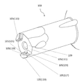
- the pocket 105 may have a bottom portion 111, a first convex portion 113, and a second convex portion 115 as illustrated in FIG.
- the bottom portion 111 is a portion facing the first surface.
- the bottom portion 111 may be in contact with the first surface of the insert 1 and may have a flat surface shape.
- the first convex portion 113 is a portion facing the first concave portion.
- the second convex portion 115 is a portion facing the second concave portion.
- the first convex portion 113 and the second convex portion 115 may respectively project from the bottom portion 111 along the direction from the side of the second end 103 b toward the side of the first end 103 a.
- the first convex portion 113 may be in contact with the first concave portion
- the second convex portion 115 may be in contact with the second concave portion.
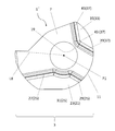
- the first convex portion 113 in the example shown in FIG. 24 has a ninth surface 117 facing the third surface and a tenth surface 119 facing the fourth surface.
- the pocket 105 further includes a first portion 123 located between the bottom portion 111 and the ninth surface 117 and a second portion 125 located between the bottom portion 111 and the tenth surface 119.
- the first portion 123 may be a curved surface connecting the bottom portion 111 and the ninth surface 117.
- the second portion 125 may be a curved surface connecting the bottom portion 111 and the tenth surface 119.
- first portion 123 and the second portion 125 have a groove shape. Specifically, a portion corresponding to the first portion 123 is shown as a first groove portion 123, and a portion corresponding to the second portion 125 is shown as a second groove portion 125. In such a configuration, the width W 1 of the first groove 123 may be larger than the width W 2 of the second groove 125.
- a main component is likely to be applied to the insert 1 in the direction from the first cutting edge toward the flank region during cutting. Therefore, the insert 1 is easy to rotate in the F1 direction which is a clockwise direction with reference to the central axis P2 of the screw hole 109. At this time, a force is easily applied to the ninth surface 117 opposed to the third surface, and stress is easily concentrated between the bottom portion 111 and the ninth surface 117. However, when the insert 1 has the above-described configuration, concentration of stress applied between the bottom 111 and the ninth surface 117 is easily avoided. Therefore, the strength of the holder 103 is high.
- the width W1 of the first groove portion 123 may be evaluated by the width in the direction orthogonal to the extending direction of the first groove portion 123, as shown in FIG.
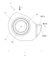
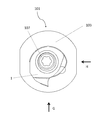
- FIG. 25 is a view of the holder 103 viewed from the first end.
- the width W2 of the second groove 125 may be evaluated by the width in the direction orthogonal to the extending direction of the second groove 125, as shown in FIG.
- the whole of the bottom portion 111 may be in contact with the first surface, and only a part of the bottom portion 111 may be in contact with the first surface.
- the entire first protrusion 113 may be in contact with the first recess, or only a part of the first protrusion 113 may be in contact with the first recess.
- the entire second protrusion 115 may be in contact with the second recess, or only a part of the second protrusion 115 may be in contact with the second recess.
- the entire ninth surface 117 may be in contact with the third surface, or only a portion of the ninth surface 117 may be in contact with the third surface.
- the whole of the tenth surface 119 may be in contact with the fourth surface, or only a part of the tenth surface 119 may be in contact with the fourth surface.
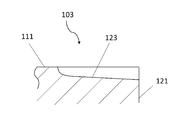
- the first groove portion 123 may have a portion which becomes shallow as it is separated from the outer peripheral surface 121 of the holder 103.
- the stress tends to be concentrated toward the portion closer to the outer peripheral surface 121 of the holder 103.
- the portion closer to the outer peripheral surface 121 of the holder 103 Stress concentration is relieved.
- the thickness in the vicinity of the screw hole 109 in the holder 103 can be secured. Therefore, the strength of the holder 103 can be improved.
- the groove bottom of the first groove 123 may have a curved shape, or may have a linear shape as shown in FIG.
- the pocket 105 may have a threaded hole 109 extending from the side of the first end 103 a to the side of the second end 103 b at the bottom 111.
- the first groove portion 123 may be in contact with the screw hole 109 and may be separated from the screw hole 109. In the example shown in FIG. 25, the first groove 123 is separated from the screw hole 109.
- the central axis P2 of the screw hole 109 in the holder 103 and the central axis P1 of the through hole 19 in the insert 1 may be coincident with or offset from each other.
- the central axes P1 and P2 coincide with each other, screwing of the insert 1 to the holder 103 can be easily performed.
- FIG. 22 shows the central axis P2 and the central axis P1 in a state in which the screw is removed. Further, in FIG. 22, the central axis P2 is indicated by a point. Note that FIG. 22 shows the cutting tool 101 in the case where the holder 103 is seen through in a plan view toward the first end.
- an imaginary straight line L9 parallel to the ridge line where the first surface 7 and the third surface 27 intersect is set. Further, an imaginary straight line parallel to the imaginary straight line L9 and passing through the central axis P1 of the through hole 19 is taken as an imaginary straight line L9 '.
- the central axis P2 may be located on the side of the first recess 21 with respect to the imaginary straight line L9 '. As described above, when the central axis P2 is eccentric with respect to the central axis P1, when the insert 1 is fixed to the holder 103 by the screw 107, the screw 107 is not easily loosened.
- the central axis P2 may be located farther from the first cutting edge 17 than the central axis P1 in the direction along the imaginary straight line L9 '. Even in such a case, when the insert 1 is fixed to the holder 103 by the screw 107, the screw 107 is not easily loosened.
- steel, cast iron or the like can be used.
- high toughness steel may be used among these members.
- the machined product is produced by cutting a work material.
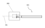
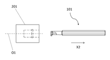
- the method of manufacturing a machined product according to the embodiment includes the following steps. That is, (1) a step of rotating the work material 201; (2) contacting the first cutting edge of the cutting tool 101 represented by the above embodiment with the rotating workpiece 201; (3) releasing the cutting tool 101 from the work material 201; Is equipped.
- the work material 201 is rotated around the axis O1, and the cutting tool 101 is brought relatively close to the work material 201.
- the first cutting edge of the cutting tool 101 is brought into contact with the rotating work material 201, and the work material 201 is cut.
- the cutting tool 101 is relatively moved away from the work material 201.
- the cutting tool 101 is moved in the X1 direction to approach the work material 201. Further, in FIG. 28, the work material 201 is cut by bringing the first cutting edge of the insert into contact with the work material 201 being rotated. Further, in FIG. 29, the cutting tool 101 is moved away in the X2 direction in a state where the work material 201 is rotated.
- the cutting tool 101 is brought into contact with the work material 201 by moving the cutting tool 101 in each process, or the cutting tool 101 is separated from the work material 201
- the cutting tool 101 is not limited to such a form.
- the work material 201 may be brought close to the cutting tool 101.
- the work material 201 may be moved away from the cutting tool 101.
- the step of rotating the work material 201 may be maintained, and the process of bringing the first cutting edge in the insert into contact with different portions of the work material 201 may be repeated.
- cut material 201 carbon steel, alloy steel, stainless steel, cast iron, or nonferrous metal etc. are mentioned, for example.
- this indication is not limited to embodiment mentioned above, It can not be overemphasized that it can be arbitrary unless it deviates from the gist of this indication.
Landscapes
- Engineering & Computer Science (AREA)
- Mechanical Engineering (AREA)
- Cutting Tools, Boring Holders, And Turrets (AREA)
Abstract
Priority Applications (4)
| Application Number | Priority Date | Filing Date | Title |
|---|---|---|---|
| US16/629,581 US11260458B2 (en) | 2017-07-11 | 2018-07-11 | Cutting insert, cutting tool and method for manufacturing machined product |
| DE112018003572.7T DE112018003572T5 (de) | 2017-07-11 | 2018-07-11 | Schneideinsatz, schneidwerkzeug und herstellungsverfahren zur herstellung eines maschinell bearbeiteten produkts |
| JP2019529767A JP7128185B2 (ja) | 2017-07-11 | 2018-07-11 | 切削インサート、切削工具及び切削加工物の製造方法 |
| CN201880045951.7A CN110869150B (zh) | 2017-07-11 | 2018-07-11 | 切削刀片、切削工具以及切削加工物的制造方法 |
Applications Claiming Priority (4)
| Application Number | Priority Date | Filing Date | Title |
|---|---|---|---|
| JP2017-135567 | 2017-07-11 | ||
| JP2017135567 | 2017-07-11 | ||
| JP2017-195958 | 2017-10-06 | ||
| JP2017195958 | 2017-10-06 |
Publications (1)
| Publication Number | Publication Date |
|---|---|
| WO2019013263A1 true WO2019013263A1 (fr) | 2019-01-17 |
Family
ID=65001350
Family Applications (1)
| Application Number | Title | Priority Date | Filing Date |
|---|---|---|---|
| PCT/JP2018/026220 Ceased WO2019013263A1 (fr) | 2017-07-11 | 2018-07-11 | Plaquette de coupe, outil de coupe et procédé de fabrication de pièce coupée |
Country Status (5)
| Country | Link |
|---|---|
| US (1) | US11260458B2 (fr) |
| JP (1) | JP7128185B2 (fr) |
| CN (1) | CN110869150B (fr) |
| DE (1) | DE112018003572T5 (fr) |
| WO (1) | WO2019013263A1 (fr) |
Cited By (1)
| Publication number | Priority date | Publication date | Assignee | Title |
|---|---|---|---|---|
| JP7699760B1 (ja) * | 2024-11-21 | 2025-06-30 | 株式会社タンガロイ | ボディ、切削工具及び切削インサート |
Families Citing this family (3)
| Publication number | Priority date | Publication date | Assignee | Title |
|---|---|---|---|---|
| ES2815542T3 (es) * | 2017-12-22 | 2021-03-30 | Ceratizit Austria Gmbh | Sistema de herramientas y procedimiento de torneado |
| EP3863786B1 (fr) * | 2018-10-10 | 2025-06-18 | Sumitomo Electric Hardmetal Corp. | Plaquette de coupe et outil de coupe |
| US11724318B2 (en) * | 2020-10-15 | 2023-08-15 | Ina Acquisition Corp. | Bit for removing a plug from a branch conduit |
Citations (5)
| Publication number | Priority date | Publication date | Assignee | Title |
|---|---|---|---|---|
| JP2002512564A (ja) * | 1997-05-02 | 2002-04-23 | イスカー・リミテツド | 切削工具組み立て体 |
| JP2006187820A (ja) * | 2005-01-04 | 2006-07-20 | Mitsubishi Materials Corp | インサート着脱式切削工具 |
| JP2013519538A (ja) * | 2010-02-17 | 2013-05-30 | イスカーリミテッド | 工具連結器 |
| JP2014504561A (ja) * | 2011-02-08 | 2014-02-24 | イスカーリミテッド | 切削工具および切削工具用切削インサート |
| JP2016514626A (ja) * | 2013-03-26 | 2016-05-23 | イスカル リミテッド | 菱形の割出し可能な切削インサートおよび切削工具 |
Family Cites Families (8)
| Publication number | Priority date | Publication date | Assignee | Title |
|---|---|---|---|---|
| DE3402547A1 (de) * | 1984-01-26 | 1985-08-08 | Hartmetall-Werkzeugfabrik Paul Horn GmbH, 7400 Tübingen | Wechselschneidkoerper, insbesondere fuer ein inneneinstich- und zirkular-werkzeug |
| JPS6175909U (fr) * | 1984-10-26 | 1986-05-22 | ||
| SE9101323D0 (sv) * | 1991-05-02 | 1991-05-02 | Mircona Ab | Anordning vid verktyg foer traanga utrymmen |
| SE523747C2 (sv) * | 2001-08-31 | 2004-05-11 | Sandvik Ab | Verktyg för spånavskiljande bearbetning med vinklad skärhållare |
| SE525583C2 (sv) * | 2002-07-01 | 2005-03-15 | Seco Tools Ab Publ | Koppling med profilerade ytor vid verktyg för spånavskiljande bearbetning |
| US8708613B2 (en) | 2012-04-10 | 2014-04-29 | Iscar, Ltd. | Left-handed and right-handed cutting tool |
| US9120154B2 (en) * | 2013-02-14 | 2015-09-01 | Iscar, Ltd. | Single-sided square-shaped indexable cutting insert and cutting tool |
| JP6258950B2 (ja) * | 2013-09-30 | 2018-01-10 | 京セラ株式会社 | 切削インサート、切削工具および切削加工物の製造方法 |
-
2018
- 2018-07-11 JP JP2019529767A patent/JP7128185B2/ja active Active
- 2018-07-11 CN CN201880045951.7A patent/CN110869150B/zh active Active
- 2018-07-11 US US16/629,581 patent/US11260458B2/en active Active
- 2018-07-11 WO PCT/JP2018/026220 patent/WO2019013263A1/fr not_active Ceased
- 2018-07-11 DE DE112018003572.7T patent/DE112018003572T5/de active Granted
Patent Citations (5)
| Publication number | Priority date | Publication date | Assignee | Title |
|---|---|---|---|---|
| JP2002512564A (ja) * | 1997-05-02 | 2002-04-23 | イスカー・リミテツド | 切削工具組み立て体 |
| JP2006187820A (ja) * | 2005-01-04 | 2006-07-20 | Mitsubishi Materials Corp | インサート着脱式切削工具 |
| JP2013519538A (ja) * | 2010-02-17 | 2013-05-30 | イスカーリミテッド | 工具連結器 |
| JP2014504561A (ja) * | 2011-02-08 | 2014-02-24 | イスカーリミテッド | 切削工具および切削工具用切削インサート |
| JP2016514626A (ja) * | 2013-03-26 | 2016-05-23 | イスカル リミテッド | 菱形の割出し可能な切削インサートおよび切削工具 |
Cited By (1)
| Publication number | Priority date | Publication date | Assignee | Title |
|---|---|---|---|---|
| JP7699760B1 (ja) * | 2024-11-21 | 2025-06-30 | 株式会社タンガロイ | ボディ、切削工具及び切削インサート |
Also Published As
| Publication number | Publication date |
|---|---|
| JPWO2019013263A1 (ja) | 2020-07-09 |
| US11260458B2 (en) | 2022-03-01 |
| JP7128185B2 (ja) | 2022-08-30 |
| CN110869150B (zh) | 2021-01-22 |
| DE112018003572T5 (de) | 2020-03-26 |
| CN110869150A (zh) | 2020-03-06 |
| US20210016363A1 (en) | 2021-01-21 |
Similar Documents
| Publication | Publication Date | Title |
|---|---|---|
| US10010939B2 (en) | Cutting insert, cutting tool, and method for manufacturing machined product | |
| JP7480291B2 (ja) | 切削インサート、切削工具及び切削加工物の製造方法 | |
| JP7128185B2 (ja) | 切削インサート、切削工具及び切削加工物の製造方法 | |
| US10252341B2 (en) | Cutting insert, cutting tool, and method for manufacturing machined product | |
| WO2019039547A1 (fr) | Insert | |
| CN112135703A (zh) | 切削刀片、切削工具以及切削加工物的制造方法 | |
| JP6185376B2 (ja) | 切削インサート、切削工具および被削加工物の製造方法 | |
| US10576548B2 (en) | Insert, cutting tool, and method for manufacturing machined product | |
| CN110944777B (zh) | 切削刀片、切削工具以及切削加工物的制造方法 | |
| US20170036279A1 (en) | Cutting tool and method for manufacturing machined product | |
| US12186816B2 (en) | Cutting insert, cutting tool and method for manufacturing machined product | |
| WO2024048257A1 (fr) | Plaquette de coupe, outil de coupe et procédé de fabrication de pièce coupée | |
| US12257638B2 (en) | Cutting insert, cutting tool and method for manufacturing machined product | |
| CN110997204A (zh) | 切削刀片、切削工具以及切削加工物的制造方法 | |
| US20240286201A1 (en) | Cutting insert, cutting tool, and method for manufacturing machined product | |
| CN115551663B (zh) | 切削刀片、切削刀具以及切削加工物的制造方法 | |
| JP6418765B2 (ja) | 切削インサート、切削工具および切削加工物の製造方法 | |
| JP7344168B2 (ja) | 切削インサート、切削工具及び切削加工物の製造方法 | |
| JP7117389B2 (ja) | 切削インサート、切削工具及び切削加工物の製造方法 | |
| JP6363355B2 (ja) | 切削インサート、切削工具および被削加工物の製造方法 |
Legal Events
| Date | Code | Title | Description |
|---|---|---|---|
| 121 | Ep: the epo has been informed by wipo that ep was designated in this application |
Ref document number: 18832177 Country of ref document: EP Kind code of ref document: A1 |
|
| ENP | Entry into the national phase |
Ref document number: 2019529767 Country of ref document: JP Kind code of ref document: A |
|
| WWP | Wipo information: published in national office |
Ref document number: 112018003572 Country of ref document: DE |
|
| 122 | Ep: pct application non-entry in european phase |
Ref document number: 18832177 Country of ref document: EP Kind code of ref document: A1 |
|
| WWG | Wipo information: grant in national office |
Ref document number: 112018003572 Country of ref document: DE |