WO2019016921A1 - Phare - Google Patents
Phare Download PDFInfo
- Publication number
- WO2019016921A1 WO2019016921A1 PCT/JP2017/026297 JP2017026297W WO2019016921A1 WO 2019016921 A1 WO2019016921 A1 WO 2019016921A1 JP 2017026297 W JP2017026297 W JP 2017026297W WO 2019016921 A1 WO2019016921 A1 WO 2019016921A1
- Authority
- WO
- WIPO (PCT)
- Prior art keywords
- projection lens
- optical
- tilting
- optical unit
- axis
- Prior art date
- Legal status (The legal status is an assumption and is not a legal conclusion. Google has not performed a legal analysis and makes no representation as to the accuracy of the status listed.)
- Ceased
Links
Images




Classifications
-
- B—PERFORMING OPERATIONS; TRANSPORTING
- B60—VEHICLES IN GENERAL
- B60Q—ARRANGEMENT OF SIGNALLING OR LIGHTING DEVICES, THE MOUNTING OR SUPPORTING THEREOF OR CIRCUITS THEREFOR, FOR VEHICLES IN GENERAL
- B60Q1/00—Arrangement of optical signalling or lighting devices, the mounting or supporting thereof or circuits therefor
- B60Q1/02—Arrangement of optical signalling or lighting devices, the mounting or supporting thereof or circuits therefor the devices being primarily intended to illuminate the way ahead or to illuminate other areas of way or environments
- B60Q1/04—Arrangement of optical signalling or lighting devices, the mounting or supporting thereof or circuits therefor the devices being primarily intended to illuminate the way ahead or to illuminate other areas of way or environments the devices being headlights
- B60Q1/06—Arrangement of optical signalling or lighting devices, the mounting or supporting thereof or circuits therefor the devices being primarily intended to illuminate the way ahead or to illuminate other areas of way or environments the devices being headlights adjustable, e.g. remotely-controlled from inside vehicle
- B60Q1/068—Arrangement of optical signalling or lighting devices, the mounting or supporting thereof or circuits therefor the devices being primarily intended to illuminate the way ahead or to illuminate other areas of way or environments the devices being headlights adjustable, e.g. remotely-controlled from inside vehicle by mechanical means
Definitions
- the present invention relates to a headlight mounted on a vehicle.
- the optical axis adjustment mechanism adjusts the optical axis by tilting the projection lens centering on a part away from the projection lens (see, for example, Patent Document 1).
- the conventional headlamp is configured as described above, the tilt range of the projection lens is large. Therefore, there is a problem that the opening for emitting the irradiation light forward of the vehicle can not be narrowed.
- the present invention has been made to solve the above-described problems, and an object thereof is to narrow an opening for emitting irradiation light forward of a vehicle by narrowing a tilt range of a projection lens.
- a headlamp according to the present invention comprises an optical unit having a light source and a projection lens, and an optical axis adjusting mechanism for adjusting the optical axis of the optical unit by tilting the optical unit around a tilting axis, the tilting axis being It is set in the projection lens.
- the tilt range of the optical unit can be narrowed, and the opening for emitting the irradiation light forward of the vehicle can be narrowed.
- FIG. 1 is a cross-sectional view showing an overview of a headlamp according to Embodiment 1;
- FIG. 2 is a side view showing the main part of the headlight according to the first embodiment.
- 5 is a diagram for explaining a tilting range of the optical unit in Embodiment 1.
- FIG. It is a reference example for helping an understanding of the headlight which concerns on Embodiment 1, and is a side view which shows the principal part of the headlight used as a reference example. It is a reference example for helping understanding of the headlight concerning Embodiment 1, and is a figure explaining the tilting range of the optical unit in FIG.
- FIG. 8 is an exploded perspective view showing the main parts of a headlamp according to a second embodiment.
- FIG. 10 is an exploded perspective view showing the main parts of a headlamp according to a third embodiment. It is the top view which looked at the principal part of the headlight of FIG. 8 in the direction of arrow D. FIG. It is the top view which showed the modification of the headlamp concerning Embodiment 3, and looked at the principal part of this headlamp in the direction of arrow D of FIG.
- FIG. 1 is a cross-sectional view showing an overview of a headlamp 1 according to a first embodiment.
- the headlamp 1 according to the first embodiment includes an optical unit 10, an upper and lower optical axis adjustment mechanism 6, a case 7, and a front lens 8 installed in an opening 7a of the case 7.
- the left side of the drawing is the front of the vehicle
- the right side of the drawing is the rear of the vehicle
- the rear side of the drawing is the vehicle right direction
- the front side of the drawing is the vehicle left direction
- the vertical direction of the drawing is the vehicle vertical direction.
- the optical unit 10 includes at least an LED (light emitting diode) 2 as a light source and a projection lens 3.
- the optical unit 10 includes a holding member 4 for holding the LED 2 and the projection lens 3 and a heat sink 5 for radiating heat generated by the LED 2.
- the optical unit 10 is housed inside the case 7 and the front lens 8. In the surface of the case 7 facing the front of the vehicle, an opening 7 a for emitting the light emitted from the optical unit 10 forward of the vehicle is formed, and the opening 7 a is covered by the front lens 8.
- the light source is not limited to the LED 2 and may be a semiconductor light source such as a laser diode.
- the upper and lower optical axis adjusting mechanism 6 adjusts the optical axis of the optical unit 10, that is, the direction in which the irradiation light is irradiated, and includes an aiming screw 6a and a nut 6b.
- the nut 6 b is coupled to the optical unit 10.
- the connection structure between the nut 6b and the optical unit 10 will be described later with reference to FIG.
- the aiming screw 6a screwed to the nut 6b has its end portion penetrated through the case 7 and exposed to the outside for rotation.
- the vertical optical axis adjustment mechanism 6 is installed on the upper side of the projection lens 3 and moves the upper side of the optical unit 10 in the front-rear direction. As the upper side of the optical unit 10 moves in the front-rear direction, the optical unit 10 tilts around the vertical tilting axis 21 set in the projection lens 3 and the optical axis is adjusted in the vertical direction.
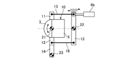
- FIG. 2 is a side view showing the main part of the headlight 1 according to the first embodiment.
- the optical unit 10 is installed in the case 7 by the upper arm 11, the lower arm 12, the auxiliary arms 13 and 14, the upper link 15 and the lower link 16.
- the upper arm 11 is fixed to the upper side of the projection lens 3 of the optical unit 10
- the lower arm 12 is fixed to the lower side of the projection lens 3.
- the upper arm 11 and the upper end portion of the auxiliary arm 13 are rotatably connected by the upper link 15 so that the upper arm 11 and the lower arm 12 and the auxiliary arm 13 are parallel, and the lower arm 12 and the auxiliary arm 13
- the lower end is rotatably connected by the lower link 16.
- an auxiliary arm 14 is rotatably connected to the lower side of the lower arm 12.
- a nut 6 b is connected to the upper end of the auxiliary arm 13.
- the aiming screw 6a is screwed into the other end of the nut 6b.
- the fixed shaft 22 is formed at the same height position as the vertically tilting shaft 21 in the auxiliary arm 13, and the fixed shaft 22 is rotatably supported by the case 7.
- the auxiliary arm 13 is rotatable about the fixed shaft 22.
- a fixed shaft 23 is formed at the lower end of the auxiliary arm 14, and the fixed shaft 23 is rotatably supported by the case 7.
- the auxiliary arm 14 can rotate around the fixed shaft 23.
- the fixed shafts 22 and 23 are, for example, ball joints.
- a vertically tilting axis 21 is set at an intersection point of an imaginary straight line formed by the upper arm 11 and the lower arm 12 aligned on a straight line and an imaginary horizontal line passing through the fixed axis 22.
- the vertical tilt axis 21 is set at the center of the projection lens 3 in the vertical direction and at the end of the projection lens 3 on the vehicle rear side, and the position of the projection lens 3 in the left and right direction does not matter. .
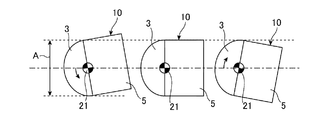
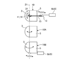
- FIG. 3 is a diagram for explaining a tilting range A of the optical unit 10 in the first embodiment.
- the optical unit 10 on the left side of the drawing is tilted downward, the optical unit 10 at the center of the drawing is not tilted, and the optical unit 10 on the right side of the drawing is tilted upward.
- the nut 6 b of the vertical optical axis adjustment mechanism 6 moves the upper end portion of the auxiliary arm 13 forward of the vehicle. Then, the upper arm 11 connected to the upper end portion of the auxiliary arm 13 by the upper link 15 also moves forward of the vehicle.
- the lower arm 12 of the lower arm 12 moves to the rear of the vehicle with the fixed shaft 22 as the center, and the lower arm 12 is connected to the lower arm of the auxiliary arm 13 by the lower link 16. Move to the rear of the vehicle with the center.
- the optical unit 10 tilts downward around the vertical tilt axis 21 in the projection lens 3 as shown on the left side of the drawing of FIG.
- the nut 6 b of the vertical optical axis adjustment mechanism 6 moves the upper end portion of the auxiliary arm 13 to the rear of the vehicle. Then, the upper arm 11 connected to the upper end portion of the auxiliary arm 13 by the upper link 15 also moves rearward of the vehicle. On the other hand, the lower arm 12 of the lower arm 12 moves with the lower link 16 to the lower end of the auxiliary arm 13 by the lower link 16 with the auxiliary arm 14. Move forward to the center of the vehicle. As a result, as shown on the right side of the drawing in FIG. 3, the optical unit 10 tilts upward about the vertical tilt axis 21 in the projection lens 3.
- FIG. 4 and FIG. 5 show reference examples for assisting the understanding of the headlamp 1 according to the first embodiment.
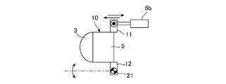
- FIG. 4 is a side view showing an essential part of a headlight according to a reference example.
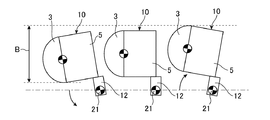
- FIG. 5 is a view for explaining the tilting range B of the optical unit 10 in FIG. In FIG. 5, the optical unit 10 on the left side of the drawing is tilted downward, the optical unit 10 at the center of the drawing is not tilted, and the optical unit 10 on the right side of the drawing is tilted upward.
- the upper arm 11 and the lower arm 12 are fixed to the end on the vehicle rear side of the optical unit 10.
- One end of a nut 6 b is connected to the upper arm 11.
- the lower arm 12 is rotatably supported by the case 7 by a ball joint or the like.
- the portion rotatably supported by the case 7 of the lower arm 12 is the vertical tilting shaft 21. While the up and down tilting axis 21 in the first embodiment is set in the projection lens 3, the up and down tilting axis 21 in the reference example is set at a position deviated from the projection lens 3.
- the nut 6 b of the vertical optical axis adjustment mechanism 6 moves the upper arm 11 forward of the vehicle. Then, the optical unit 10 tilts downward about the vertical tilt axis 21 on the lower arm 12 as shown on the left side of FIG.
- the nut 6b of the vertical optical axis adjustment mechanism 6 moves the upper arm 11 to the rear of the vehicle. Then, the optical unit 10 tilts upward about the vertical tilt axis 21 on the lower arm 12 as shown on the right side of the drawing of FIG. 5.
- the up and down tilting axis 21 is set on the lower arm 12 whereas in the first embodiment, the up and down tilting axis 21 is set in the projection lens 3, so the tilting range B of the optical unit 10 of the reference example
- the tilt range A of the optical unit 10 of the first embodiment is narrower than that of the first embodiment. Therefore, in the reference example, the size of the opening 7a of the case 7 needs to be larger than the tilting range B, whereas in the first embodiment, the size of the opening 7a of the case 7 is larger than the tilting range A It is possible to narrow the opening 7a for emitting the irradiation light forward of the vehicle.
- the headlamp 1 tilts the optical axis of the optical unit 10 by tilting the optical unit 10 having the LED 2 and the projection lens 3 and the optical unit 10 up and down about the tilting axis 21. And an upper and lower optical axis adjusting mechanism 6 for adjusting.
- the up and down tilting axis 21 is set in the projection lens 3.
- the tilting range A of the optical unit 10 is narrowed, and as a result, the opening 7a for emitting the irradiation light forward of the vehicle can be narrowed.
- the up and down tilting axis 21 is set at the center of the projection lens 3, and the up and down optical axis adjustment mechanism 6 is installed above the projection lens 3.
- the structural example which adjusts the optical axis of the optical unit 10 to an up-down direction by tilting in a direction was demonstrated, it is not limited to this structure.
- the up and down tilting axis 21 is set at the center of the projection lens 3, but may be set below the center of the projection lens 3.
- the vertical optical axis adjustment mechanism 6 may be installed below the projection lens 3. That is, in FIG. 2, the nut 6 b of the vertical optical axis adjustment mechanism 6 may be connected to the lower end portion of the auxiliary arm 13. In this case, it is preferable that the up and down tilting axis 21 be set at the center of the projection lens 3 or above the center of the projection lens 3.
- the upper and lower optical axis adjustment mechanism 6 may be installed on the upper side and the lower side of the projection lens 3 respectively. That is, the headlight 1 includes the two upper and lower optical axis adjustment mechanisms 6, and the nut 6b of one upper and lower optical axis adjustment mechanism 6 is connected to the upper end portion of the auxiliary arm 13 in FIG. The nut 6b of the other upper and lower optical axis adjustment mechanism 6 is connected to the part. In this case, it is desirable that the up and down tilting axis 21 be set at the center of the projection lens 3.
- FIG. 6 is an exploded perspective view showing the main part of the headlamp 1 according to the second embodiment.
- the parts in FIG. 6 that are the same as or correspond to those in FIGS.
- the left and right optical axis adjustment mechanism 9 adjusts the optical axis of the optical unit 10 in the left and right direction, and includes an aiming screw and a nut 9 b (not shown).
- One end of the nut 9 b is fixed to one side of the optical unit 10 in the left-right direction of the vehicle.
- An aiming screw (not shown) is screwed into the other end of the nut 9 b. Similar to the aiming screw 6a of the upper and lower optical axis adjusting mechanism, the end of the aiming screw of the left and right optical axis adjusting mechanism 9 passes through the case 7 and is exposed to the outside to be rotated.
- FIG. 7 is a plan view of an essential part of the headlight 1 of FIG.
- the upper side of the drawing is the right side of the vehicle
- the lower side of the drawing is the left side of the vehicle.
- the left and right optical axis adjustment mechanism 9 is installed on the left side of the projection lens 3, and the nut 9b moves the left side of the optical unit 10 in the vehicle longitudinal direction.
- the optical unit 10 tilts around the left and right tilting axis 24 set in the projection lens 3, and the optical axis is adjusted in the left-right direction.
- a left and right tilting axis 24 is set at an intersection point of an imaginary vertical line passing through the fixed axis 23 and an imaginary horizontal line passing through the position where the nut 9 b and the optical unit 10 are fixed.
- the left and right tilting axis 24 is set at the center in the vertical and horizontal directions of the projection lens 3 and at the end on the vehicle rear side in the projection lens 3.
- the respective ends of the upper link 15 and the lower link 16 are connected to the upper arm 11, the lower arm 12 and the auxiliary arms 13 and 14 by, for example, a ball joint. Therefore, when the optical unit 10 tilts around the left and right tilting shaft 24, the auxiliary arms 13, 14 etc. interlock with the optical unit 10 and tilt horizontally, but the nuts 6b, 9b etc. do not tilt horizontally, Maintain the same attitude.
- the headlamp 1 of the second embodiment includes the left and right optical axis adjustment mechanism 9.
- the left and right optical axis adjustment mechanism 9 is installed on the left side of the projection lens 3 and adjusts the optical axis of the optical unit 10 in the left and right direction by tilting the optical unit 10 in the left and right direction around the left and right tilting axis 24.
- the tilting range of the optical unit 10 becomes narrower than when the left and right tilting axis 24 is set at a position other than the projection lens 3.
- the left and right tilting axis 24 is set at the center of the projection lens 3, and the left and right optical axis adjusting mechanism 9 is installed on the left side of the projection lens 3.
- the present invention is not limited to this configuration.
- the left and right tilting axis 24 is set at the center of the projection lens 3, but may be set to the right of the center of the projection lens 3.
- the left and right optical axis adjustment mechanism 9 may be installed on the right side of the projection lens 3.
- the left and right tilting axis 24 is preferably set to the center of the projection lens 3 or to the left of the center of the projection lens 3.
- left and right optical axis adjustment mechanisms 9 may be installed on the left side and the right side of the projection lens 3 respectively. In this case, it is desirable that the left and right tilting axis 24 be set at the center of the projection lens 3.
- FIG. 8 is an exploded perspective view showing the main part of the headlamp 1 according to the third embodiment.
- FIG. 9 is a plan view of the main part of the headlight 1 of FIG.
- the same or corresponding parts as those in FIGS. 1 to 3, 6 and 7 are denoted by the same reference numerals and the description thereof will be omitted.
- three optical units 10, 10 ⁇ / b> A, 10 ⁇ / b> B are housed inside the headlight 1.
- the configuration of the optical units 10A and 10B is the same as the configuration of the optical unit 10.
- the optical units 10, 10A and 10B are connected.
- the vertical optical axis adjustment mechanism 6 adjusts the optical axes of the optical units 10, 10A and 10B in the vertical direction, and includes an aiming screw 6a and a nut 6b (not shown). One end of the nut 6 b is connected to the upper end of the auxiliary arm 13 provided for the optical unit 10. An aiming screw 6a (not shown) is screwed into the other end of the nut 6b.
- the vertical optical axis adjustment mechanism 6 tilts the optical unit 10 in the vertical direction around the vertical tilting axis 21, the optical units 10A and 10B connected to the optical unit 10 also tilt in an interlocking manner.
- the vertical optical axis adjustment mechanism 6 can adjust the optical axes of the optical units 10, 10A, and 10B in the vertical direction.
- the left and right optical axis adjustment mechanism 9 adjusts the optical axes of the optical units 10, 10A and 10B in the left and right direction, and has an aiming screw and a nut 9b (not shown). One end of the nut 9b is fixed to the optical unit 10B. An aiming screw (not shown) is screwed into the other end of the nut 9 b.
- the left and right optical axis adjustment mechanism 9 tilts the optical unit 10B in the left and right direction around the left and right tilting axis 24, the optical units 10 and 10A connected to the optical unit 10B also tilt in an interlocking manner.
- the left and right optical axis adjustment mechanism 9 can adjust the optical axes of the optical units 10, 10A, and 10B in the left and right direction.
- FIG. 10 shows a modification of the headlamp 1 according to the third embodiment, and is a plan view of the main part of the headlamp 1 as viewed in the direction of the arrow D in FIG.
- the auxiliary arm 14 having the fixed shaft 23 is rotatably connected to the lower side of the lower arm 12.
- the auxiliary arm 14 having the fixed shaft 23 is fixed to the lower side of the optical unit 10A. Therefore, in the configuration example of FIG. 10, the left and right tilting axis 24 is set in the projection lens 3 of the optical unit 10A.
- the left and right optical axis adjustment mechanism 9 tilts the optical unit 10B in the left and right direction around the left and right tilting axis 24 set in the projection lens 3 of the optical unit 10A
- the optical units 10 and 10A connected to the optical unit 10B also Tilt in conjunction.
- the left and right optical axis adjustment mechanism 9 can adjust the optical axes of the optical units 10, 10A, and 10B in the left and right direction.
- the left and right tilting axis 24 may be set in any of the projection lenses 3 of the optical units 10, 10A, 10B.
- the headlamp 1 which concerns on Embodiment 3 is provided with several optical unit 10, 10A, 10B.
- the vertical optical axis adjustment mechanism 6 interlocks the plurality of optical units 10, 10A and 10B and tilts them about the vertical tilting axis 21.
- the left and right optical axis adjusting mechanism 9 interlocks the plurality of optical units 10, 10A and 10B and tilts them around the left and right tilting axis 24.
- the opening 7a can be narrowed also in the headlamp 1 provided with the plurality of optical units 10, 10A, 10B.
- the headlamp 1 includes the vertical optical axis adjustment mechanism 6 and the left and right optical axis adjustment mechanism 9 to adjust the optical axis of the optical unit 10 in the vertical and horizontal directions.
- the left and right optical axis adjustment mechanism 9 may be provided to adjust the optical axis of the optical unit 10 in the left and right direction.
- the present invention allows free combination of each embodiment, modification of any component of each embodiment, or omission of any component of each embodiment. It is.
- the headlight according to the present invention has a narrow opening, it is suitable for use in a small-sized headlight or the like.
Landscapes
- Engineering & Computer Science (AREA)
- Mechanical Engineering (AREA)
- Non-Portable Lighting Devices Or Systems Thereof (AREA)
Abstract
La présente invention concerne un phare (1) qui comprend : une unité optique (10) qui a une DEL (2) et une lentille de projection (3) ; et un mécanisme de réglage d'axe optique vertical (6) qui règle l'axe optique de l'unité optique (10) en inclinant l'unité optique (10) autour d'un arbre d'inclinaison vertical (21). L'arbre d'inclinaison vertical (21) est placé dans la lentille de projection (3).
Priority Applications (1)
| Application Number | Priority Date | Filing Date | Title |
|---|---|---|---|
| PCT/JP2017/026297 WO2019016921A1 (fr) | 2017-07-20 | 2017-07-20 | Phare |
Applications Claiming Priority (1)
| Application Number | Priority Date | Filing Date | Title |
|---|---|---|---|
| PCT/JP2017/026297 WO2019016921A1 (fr) | 2017-07-20 | 2017-07-20 | Phare |
Publications (1)
| Publication Number | Publication Date |
|---|---|
| WO2019016921A1 true WO2019016921A1 (fr) | 2019-01-24 |
Family
ID=65016620
Family Applications (1)
| Application Number | Title | Priority Date | Filing Date |
|---|---|---|---|
| PCT/JP2017/026297 Ceased WO2019016921A1 (fr) | 2017-07-20 | 2017-07-20 | Phare |
Country Status (1)
| Country | Link |
|---|---|
| WO (1) | WO2019016921A1 (fr) |
Citations (8)
| Publication number | Priority date | Publication date | Assignee | Title |
|---|---|---|---|---|
| JP2007250327A (ja) * | 2006-03-15 | 2007-09-27 | Stanley Electric Co Ltd | ドラム型可変遮光板及び該遮光板を使用したヘッドライト |
| US20110007519A1 (en) * | 2009-07-10 | 2011-01-13 | Maxzone Auto Parts Corp. | Rotatable vehicular lamp |
| DE202011003404U1 (de) * | 2011-03-01 | 2011-05-12 | Automotive Lighting Reutlingen Gmbh | Scheinwerfer eines Kraftfahrzeugs |
| US20110122640A1 (en) * | 2009-11-23 | 2011-05-26 | Maxzone Vehichle Lighting Corp. | Apparatus for controlling movement of a lamp unit relative to an automobile body |
| WO2015004905A1 (fr) * | 2013-07-10 | 2015-01-15 | 三菱電機株式会社 | Unité de phare et phare |
| JP2015015187A (ja) * | 2013-07-05 | 2015-01-22 | 株式会社小糸製作所 | 車輌用前照灯 |
| WO2015053107A1 (fr) * | 2013-10-09 | 2015-04-16 | 株式会社小糸製作所 | Lampe de véhicule |
| WO2015163150A1 (fr) * | 2014-04-24 | 2015-10-29 | 株式会社小糸製作所 | Dispositif d'éclairage pour véhicule |
-
2017
- 2017-07-20 WO PCT/JP2017/026297 patent/WO2019016921A1/fr not_active Ceased
Patent Citations (8)
| Publication number | Priority date | Publication date | Assignee | Title |
|---|---|---|---|---|
| JP2007250327A (ja) * | 2006-03-15 | 2007-09-27 | Stanley Electric Co Ltd | ドラム型可変遮光板及び該遮光板を使用したヘッドライト |
| US20110007519A1 (en) * | 2009-07-10 | 2011-01-13 | Maxzone Auto Parts Corp. | Rotatable vehicular lamp |
| US20110122640A1 (en) * | 2009-11-23 | 2011-05-26 | Maxzone Vehichle Lighting Corp. | Apparatus for controlling movement of a lamp unit relative to an automobile body |
| DE202011003404U1 (de) * | 2011-03-01 | 2011-05-12 | Automotive Lighting Reutlingen Gmbh | Scheinwerfer eines Kraftfahrzeugs |
| JP2015015187A (ja) * | 2013-07-05 | 2015-01-22 | 株式会社小糸製作所 | 車輌用前照灯 |
| WO2015004905A1 (fr) * | 2013-07-10 | 2015-01-15 | 三菱電機株式会社 | Unité de phare et phare |
| WO2015053107A1 (fr) * | 2013-10-09 | 2015-04-16 | 株式会社小糸製作所 | Lampe de véhicule |
| WO2015163150A1 (fr) * | 2014-04-24 | 2015-10-29 | 株式会社小糸製作所 | Dispositif d'éclairage pour véhicule |
Similar Documents
| Publication | Publication Date | Title |
|---|---|---|
| JP6072415B2 (ja) | 車両用灯具 | |
| JP5042093B2 (ja) | 車両用前照灯 | |
| US20160313089A1 (en) | Externally adjustable gun sight | |
| WO2019039051A1 (fr) | Équipement d'éclairage de véhicule | |
| US20080198614A1 (en) | Vehicular lamp | |
| JP6377400B2 (ja) | 車両用灯具 | |
| CN103727475B (zh) | 车辆用前照灯 | |
| CN113669685B (zh) | 车辆用灯具 | |
| JP2015170423A (ja) | 車両用灯具 | |
| US20210221278A1 (en) | Central Pivot Region | |
| JP6986157B2 (ja) | 第1及び第2の軸線周りに車両投光器の少なくとも1つの光学関連構成部材を旋回させるための調整システム | |
| JP5166917B2 (ja) | 車両用前照灯 | |
| KR102835453B1 (ko) | 차량용 램프 | |
| EP3670260B1 (fr) | Dispositif d'éclairage pour phares de véhicules | |
| JP5708987B2 (ja) | 車両用灯具ユニット | |
| CN116215361B (zh) | 用于同时调整机动车的照明设备的光模块的调整装置 | |
| JP7183478B2 (ja) | 回転調整機構及び前照灯装置 | |
| WO2019016921A1 (fr) | Phare | |
| TWM639712U (zh) | 具有遠近燈切換結構的車燈 | |
| CN113423605A (zh) | 用于机动车辆前灯的照明设备 | |
| TWI829416B (zh) | 具有遠近燈切換結構的車燈 | |
| JP6685130B2 (ja) | 車両用灯具 | |
| KR102794699B1 (ko) | 차량용 램프 | |
| JP7066072B2 (ja) | 前照灯装置 | |
| JP6817038B2 (ja) | 車輌用前照灯 |
Legal Events
| Date | Code | Title | Description |
|---|---|---|---|
| 121 | Ep: the epo has been informed by wipo that ep was designated in this application |
Ref document number: 17918240 Country of ref document: EP Kind code of ref document: A1 |
|
| NENP | Non-entry into the national phase |
Ref country code: DE |
|
| 122 | Ep: pct application non-entry in european phase |
Ref document number: 17918240 Country of ref document: EP Kind code of ref document: A1 |
|
| NENP | Non-entry into the national phase |
Ref country code: JP |