WO2019016970A1 - Dispositif de verrouillage de portière de véhicule - Google Patents
Dispositif de verrouillage de portière de véhicule Download PDFInfo
- Publication number
- WO2019016970A1 WO2019016970A1 PCT/JP2017/038155 JP2017038155W WO2019016970A1 WO 2019016970 A1 WO2019016970 A1 WO 2019016970A1 JP 2017038155 W JP2017038155 W JP 2017038155W WO 2019016970 A1 WO2019016970 A1 WO 2019016970A1
- Authority
- WO
- WIPO (PCT)
- Prior art keywords
- cable
- door latch
- door
- inner cable
- latch device
- Prior art date
- Legal status (The legal status is an assumption and is not a legal conclusion. Google has not performed a legal analysis and makes no representation as to the accuracy of the status listed.)
- Ceased
Links
Images



Classifications
-
- F—MECHANICAL ENGINEERING; LIGHTING; HEATING; WEAPONS; BLASTING
- F16—ENGINEERING ELEMENTS AND UNITS; GENERAL MEASURES FOR PRODUCING AND MAINTAINING EFFECTIVE FUNCTIONING OF MACHINES OR INSTALLATIONS; THERMAL INSULATION IN GENERAL
- F16C—SHAFTS; FLEXIBLE SHAFTS; ELEMENTS OR CRANKSHAFT MECHANISMS; ROTARY BODIES OTHER THAN GEARING ELEMENTS; BEARINGS
- F16C1/00—Flexible shafts; Mechanical means for transmitting movement in a flexible sheathing
- F16C1/10—Means for transmitting linear movement in a flexible sheathing, e.g. "Bowden-mechanisms"
- F16C1/102—Arrangements to mount end fittings of the sheathings to support walls or brackets
-
- B—PERFORMING OPERATIONS; TRANSPORTING
- B60—VEHICLES IN GENERAL
- B60J—WINDOWS, WINDSCREENS, NON-FIXED ROOFS, DOORS, OR SIMILAR DEVICES FOR VEHICLES; REMOVABLE EXTERNAL PROTECTIVE COVERINGS SPECIALLY ADAPTED FOR VEHICLES
- B60J5/00—Doors
- B60J5/04—Doors arranged at the vehicle sides
- B60J5/0468—Fixation or mounting means specific for door components
-
- E—FIXED CONSTRUCTIONS
- E05—LOCKS; KEYS; WINDOW OR DOOR FITTINGS; SAFES
- E05B—LOCKS; ACCESSORIES THEREFOR; HANDCUFFS
- E05B77/00—Vehicle locks characterised by special functions or purposes
- E05B77/34—Protection against weather or dirt, e.g. against water ingress
-
- E—FIXED CONSTRUCTIONS
- E05—LOCKS; KEYS; WINDOW OR DOOR FITTINGS; SAFES
- E05B—LOCKS; ACCESSORIES THEREFOR; HANDCUFFS
- E05B79/00—Mounting or connecting vehicle locks or parts thereof
- E05B79/10—Connections between movable lock parts
- E05B79/20—Connections between movable lock parts using flexible connections, e.g. Bowden cables
-
- F—MECHANICAL ENGINEERING; LIGHTING; HEATING; WEAPONS; BLASTING
- F16—ENGINEERING ELEMENTS AND UNITS; GENERAL MEASURES FOR PRODUCING AND MAINTAINING EFFECTIVE FUNCTIONING OF MACHINES OR INSTALLATIONS; THERMAL INSULATION IN GENERAL
- F16C—SHAFTS; FLEXIBLE SHAFTS; ELEMENTS OR CRANKSHAFT MECHANISMS; ROTARY BODIES OTHER THAN GEARING ELEMENTS; BEARINGS
- F16C1/00—Flexible shafts; Mechanical means for transmitting movement in a flexible sheathing
- F16C1/10—Means for transmitting linear movement in a flexible sheathing, e.g. "Bowden-mechanisms"
-
- F—MECHANICAL ENGINEERING; LIGHTING; HEATING; WEAPONS; BLASTING
- F16—ENGINEERING ELEMENTS AND UNITS; GENERAL MEASURES FOR PRODUCING AND MAINTAINING EFFECTIVE FUNCTIONING OF MACHINES OR INSTALLATIONS; THERMAL INSULATION IN GENERAL
- F16C—SHAFTS; FLEXIBLE SHAFTS; ELEMENTS OR CRANKSHAFT MECHANISMS; ROTARY BODIES OTHER THAN GEARING ELEMENTS; BEARINGS
- F16C1/00—Flexible shafts; Mechanical means for transmitting movement in a flexible sheathing
- F16C1/10—Means for transmitting linear movement in a flexible sheathing, e.g. "Bowden-mechanisms"
- F16C1/107—Sealing details
-
- F—MECHANICAL ENGINEERING; LIGHTING; HEATING; WEAPONS; BLASTING
- F16—ENGINEERING ELEMENTS AND UNITS; GENERAL MEASURES FOR PRODUCING AND MAINTAINING EFFECTIVE FUNCTIONING OF MACHINES OR INSTALLATIONS; THERMAL INSULATION IN GENERAL
- F16C—SHAFTS; FLEXIBLE SHAFTS; ELEMENTS OR CRANKSHAFT MECHANISMS; ROTARY BODIES OTHER THAN GEARING ELEMENTS; BEARINGS
- F16C1/00—Flexible shafts; Mechanical means for transmitting movement in a flexible sheathing
- F16C1/10—Means for transmitting linear movement in a flexible sheathing, e.g. "Bowden-mechanisms"
- F16C1/12—Arrangements for transmitting movement to or from the flexible member
- F16C1/14—Construction of the end-piece of the flexible member; Attachment thereof to the flexible member
-
- F—MECHANICAL ENGINEERING; LIGHTING; HEATING; WEAPONS; BLASTING
- F16—ENGINEERING ELEMENTS AND UNITS; GENERAL MEASURES FOR PRODUCING AND MAINTAINING EFFECTIVE FUNCTIONING OF MACHINES OR INSTALLATIONS; THERMAL INSULATION IN GENERAL
- F16C—SHAFTS; FLEXIBLE SHAFTS; ELEMENTS OR CRANKSHAFT MECHANISMS; ROTARY BODIES OTHER THAN GEARING ELEMENTS; BEARINGS
- F16C1/00—Flexible shafts; Mechanical means for transmitting movement in a flexible sheathing
- F16C1/10—Means for transmitting linear movement in a flexible sheathing, e.g. "Bowden-mechanisms"
- F16C1/12—Arrangements for transmitting movement to or from the flexible member
- F16C1/14—Construction of the end-piece of the flexible member; Attachment thereof to the flexible member
- F16C1/145—Attachment of the end-piece to the flexible member
-
- F—MECHANICAL ENGINEERING; LIGHTING; HEATING; WEAPONS; BLASTING
- F16—ENGINEERING ELEMENTS AND UNITS; GENERAL MEASURES FOR PRODUCING AND MAINTAINING EFFECTIVE FUNCTIONING OF MACHINES OR INSTALLATIONS; THERMAL INSULATION IN GENERAL
- F16C—SHAFTS; FLEXIBLE SHAFTS; ELEMENTS OR CRANKSHAFT MECHANISMS; ROTARY BODIES OTHER THAN GEARING ELEMENTS; BEARINGS
- F16C1/00—Flexible shafts; Mechanical means for transmitting movement in a flexible sheathing
- F16C1/10—Means for transmitting linear movement in a flexible sheathing, e.g. "Bowden-mechanisms"
- F16C1/12—Arrangements for transmitting movement to or from the flexible member
- F16C1/16—Arrangements for transmitting movement to or from the flexible member in which the end-piece is guided rectilinearly
-
- F—MECHANICAL ENGINEERING; LIGHTING; HEATING; WEAPONS; BLASTING
- F16—ENGINEERING ELEMENTS AND UNITS; GENERAL MEASURES FOR PRODUCING AND MAINTAINING EFFECTIVE FUNCTIONING OF MACHINES OR INSTALLATIONS; THERMAL INSULATION IN GENERAL
- F16C—SHAFTS; FLEXIBLE SHAFTS; ELEMENTS OR CRANKSHAFT MECHANISMS; ROTARY BODIES OTHER THAN GEARING ELEMENTS; BEARINGS
- F16C1/00—Flexible shafts; Mechanical means for transmitting movement in a flexible sheathing
- F16C1/10—Means for transmitting linear movement in a flexible sheathing, e.g. "Bowden-mechanisms"
- F16C1/20—Construction of flexible members moved to and fro in the sheathing
- F16C1/205—Details of the outer surface of the flexible member, e.g. coatings
-
- F—MECHANICAL ENGINEERING; LIGHTING; HEATING; WEAPONS; BLASTING
- F16—ENGINEERING ELEMENTS AND UNITS; GENERAL MEASURES FOR PRODUCING AND MAINTAINING EFFECTIVE FUNCTIONING OF MACHINES OR INSTALLATIONS; THERMAL INSULATION IN GENERAL
- F16C—SHAFTS; FLEXIBLE SHAFTS; ELEMENTS OR CRANKSHAFT MECHANISMS; ROTARY BODIES OTHER THAN GEARING ELEMENTS; BEARINGS
- F16C1/00—Flexible shafts; Mechanical means for transmitting movement in a flexible sheathing
- F16C1/24—Lubrication; Lubricating equipment
-
- E—FIXED CONSTRUCTIONS
- E05—LOCKS; KEYS; WINDOW OR DOOR FITTINGS; SAFES
- E05B—LOCKS; ACCESSORIES THEREFOR; HANDCUFFS
- E05B79/00—Mounting or connecting vehicle locks or parts thereof
- E05B79/02—Mounting of vehicle locks or parts thereof
- E05B79/06—Mounting of handles, e.g. to the wing or to the lock
-
- E—FIXED CONSTRUCTIONS
- E05—LOCKS; KEYS; WINDOW OR DOOR FITTINGS; SAFES
- E05B—LOCKS; ACCESSORIES THEREFOR; HANDCUFFS
- E05B85/00—Details of vehicle locks not provided for in groups E05B77/00 - E05B83/00
- E05B85/20—Bolts or detents
- E05B85/24—Bolts rotating about an axis
- E05B85/243—Bolts rotating about an axis with a bifurcated bolt
-
- E—FIXED CONSTRUCTIONS
- E05—LOCKS; KEYS; WINDOW OR DOOR FITTINGS; SAFES
- E05Y—INDEXING SCHEME ASSOCIATED WITH SUBCLASSES E05D AND E05F, RELATING TO CONSTRUCTION ELEMENTS, ELECTRIC CONTROL, POWER SUPPLY, POWER SIGNAL OR TRANSMISSION, USER INTERFACES, MOUNTING OR COUPLING, DETAILS, ACCESSORIES, AUXILIARY OPERATIONS NOT OTHERWISE PROVIDED FOR, APPLICATION THEREOF
- E05Y2201/00—Constructional elements; Accessories therefor
- E05Y2201/60—Suspension or transmission members; Accessories therefor
- E05Y2201/622—Suspension or transmission members elements
- E05Y2201/644—Flexible elongated pulling elements
- E05Y2201/654—Cables
-
- E—FIXED CONSTRUCTIONS
- E05—LOCKS; KEYS; WINDOW OR DOOR FITTINGS; SAFES
- E05Y—INDEXING SCHEME ASSOCIATED WITH SUBCLASSES E05D AND E05F, RELATING TO CONSTRUCTION ELEMENTS, ELECTRIC CONTROL, POWER SUPPLY, POWER SIGNAL OR TRANSMISSION, USER INTERFACES, MOUNTING OR COUPLING, DETAILS, ACCESSORIES, AUXILIARY OPERATIONS NOT OTHERWISE PROVIDED FOR, APPLICATION THEREOF
- E05Y2900/00—Application of doors, windows, wings or fittings thereof
- E05Y2900/50—Application of doors, windows, wings or fittings thereof for vehicles
- E05Y2900/53—Type of wing
- E05Y2900/531—Doors
Definitions
- the present invention relates to a vehicle door latch device provided with a Bowden cable for transmitting an operation of an outside handle to a door latch mechanism.
- the door latch mechanism is disposed in the door, and enables the door to be opened by releasing engagement with the striker on the vehicle body side based on the door opening operation of the outside handle provided on the vehicle outside of the door.
- a Bowden cable is employed as means for transmitting the door opening operation of the outside handle to the door latch device.
- the Bowden cable described in Patent Document 1 includes an outer cable and an inner cable inserted into the outer cable.
- One end of the inner cable is connected to the outside handle side, and the other end is connected to the release lever of the door latch mechanism. As a result, when the outside handle is opened, the inner cable is pulled up to operate the release lever.
- An object of this invention is to provide the door latch apparatus for vehicles which prevented the rain water penetration in the outer cable of a Bowden cable in view of the said subject.
- the technical means in the present invention comprises an operation handle supported on a handle base provided on a door, a door latch mechanism for holding the door in a closed state, and the handle at one end
- the inner cable is fixed to the base and the other end is inserted through the outer cable and the outer cable fixed to the door latch mechanism, one end is connected to the operation handle, and the other end is connected to the release lever of the door latch mechanism
- an elastic cap having a cylindrical covering portion for covering the inner cable extending from one end of the outer cable along the moving direction thereof.
- the covering portion of the elastic cap is formed into a bellows shape that can expand and contract in the moving direction of the inner cable, and the inner cable is adhered to the outlet of the covering portion.
- grease is filled in the elastic cap.
- the door latch mechanism has a cable holding portion that fixes the other end of the outer cable, and the cable holding portion is engaged with the Bowden cable in the axial direction and around the axis of the outer cable. Fix the other end.
- the elastic cap covering the inner cable extending from the upward end of the outer cable, it is possible to prevent rainwater infiltration into the outer cable and obtain a stable operation over a long period of time. it can.
- FIG. 6 is a longitudinal sectional view of the outside handle according to the first embodiment in an operated state. It is a longitudinal cross-sectional view in the non-operation state of the outside handle in 2nd Example.
- FIG. 10 is a cross-sectional view taken along line XX in FIG.
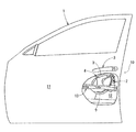
- the vehicle door latch device 10 includes a door latch mechanism 2, an outside handle operation handle 3 (an example of an operation handle), and a Bowden cable. 4 and the elastic cap 7 of the first embodiment (see FIGS. 2, 4 and 6) or the elastic cap 8 of the second embodiment (see FIGS. 5 and 7).
- the door latch mechanism 2 is disposed in the door 1 of the vehicle.
- the outside handle 3 is disposed outside the door 1 of the vehicle.
- the Bowden cable 4 has an outer cable 41 for transmitting a door opening operation of the outside handle 3 to a release lever 24 described later of the door latch mechanism 2 and an inner cable 42 inserted into the outer cable 41.
- the elastic cap 7 of the first embodiment and the elastic cap 8 of the second embodiment prevent rainwater from entering the outer cable 41 in the Bowden cable 4.
- the outside handle 3 is arrange
- the door 1 is composed of an outer panel 11 outside the vehicle and an inner panel 12 inside the vehicle.
- the front end portion of the door 1 is pivotably supported on the side of the vehicle body by a door hinge (not shown) having a rotation axis whose axial direction is in the vertical direction.
- An outside handle 3 is disposed on the outer surface of the outer panel 11.
- a door beam 13 in the front-rear direction is fixed to the inner surface of the outer panel 11 in the door 1.
- the door latch mechanism 2 has a meshing portion including a latch 22 and a ratchet 23, various levers, and a housing 21.
- the latch 22 can be engaged and disengaged with the striker S fixed to the vehicle body side.
- the ratchet 23 is engageable with the latch 22.
- the various levers are connected directly / indirectly to the ratchet 23.
- the housing 21 is made of synthetic resin that covers various levers.
- the various levers also include the release lever 24.
- the release lever 24 is pivotally supported at a lower portion in the housing 21.
- a terminal 46 fixed to the downward end of the inner cable 42 of the Bowden cable 4 is connected to the connecting portion 24 a of the release lever 24 that protrudes from the housing 21.
- the release lever 24 inputs the door open operation of the outside handle 3 to release the ratchet 23 and release the engagement between the ratchet 23 and the latch 22 to allow the door 1 to open.
- a cable holding portion 25 for fixing an end portion of the outer cable 41 of the Bowden cable 4 is integrally formed on a portion of the housing 21 above the release lever 24 (see FIGS. 3 and 8).
- the configurations of the cable holding portion 25 and the end of the outer cable 41 will be described in detail later.
- the outside handle 3 is supported by a handle base 5 fixed to the inner surface of the outer panel 11 so as to be able to pivot outward around an axis of which axis is in the vertical direction.
- the lever base 6 interlocked with the door opening operation of the outside handle 3 is pivotally supported on the handle base 5 so as to be rotatable about a shaft 6a whose axial direction is the front-rear direction. Be done.
- the end portion 45 fixed to the upper end of the inner cable 42 is connected to the connecting portion 6 b which is the turning end of the lever 6.
- the door opening operation of the outside handle 3 is transmitted to the release lever 24 of the door latch mechanism 2 via the lever 6 and the inner cable 42.
- the Bowden cable 4 has a bendable outer cable 41 and a bendable inner cable 42 inserted through the outer cable 41.
- the upper end (one end) of the Bowden cable 4 is connected to the outside handle 3 side, and the lower end (the other end) is connected to the door latch mechanism 2 side.
- the Bowden cable 4 In the configuration in which the Bowden cable 4 is wired in the door 1, as shown in FIGS. 1 and 2, it extends downward and obliquely forward along the inner side surface of the outer panel 11 from the side of the outside handle 3 which is the upper end. After that, it turns upward and extends further downward to the side of the door latch mechanism 2 which is the lower end.
- the surface of the inner cable 42 is galvanized. In this way, the occurrence of rusting of the inner cable 42 can be prevented, and smooth slidability can be obtained.
- a cylindrical shock absorbing material 9 is externally fitted to the outer cable 41 overlapping the door beam 13 in the vehicle inside-outside direction in order to suppress abnormal noise generation. Ru.
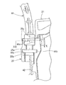
- one end of the outer cable 41 which is directed upward, is fixed to the holding portion 5a of the handle base 5 by a cylindrical handle side end cap 43 fixed to the one end. Ru.
- the inner cable 42 extending upward from the tip of the handle side end cap 43 is connected by the end 45 fixed to the tip thereof. Connected to The end portion 45 of the inner cable 42 may be directly connected to the movable portion of the outside handle 4 instead of being connected to the connecting portion 6 b of the lever 6. In this case, the lever 6 is omitted.
- the portion of the inner cable 42 extending upward from the tip of the handle end cap 43 is the handle side protruding cable 42a (FIG. 4, FIG. 5, FIG. 6A and FIG. 6B and FIGS. 7A and 7B).
- the elastic cap 7 made of rubber of the first embodiment shown in FIG. 4 or the elastic cap 8 made of rubber of the second embodiment shown in FIG. 5 is fixed to the handle side end cap 43 fixed to one end of the outer cable 41 Be done.
- Each of the elastic caps 7 and 8 prevents rainwater from invading the outer cable 41 from one end of the outer cable 41 by covering the handle side protruding cable 42 a of the inner cable 42.
- Each elastic cap 7, 8 will be described in detail later.
- the other end of the outer cable 41 which is directed downward, is fixed to the cable holding portion 25 of the door latch mechanism 2 by the door latch side end cap 44 fixed to the other end.
- the inner cable 42 extending downward from the tip (lower end) of the door latch side end cap 44 is connected to the release lever 24 of the door latch mechanism 2 by the end 46 fixed to the tip.
- the cable holding portion 25 of the door latch mechanism 2 has a U-shaped in a plan view with the side facing the rear panel 12a (see FIG. 10) of the inner panel 12 to which the door latch mechanism 2 is fixed open. And the sandwiching portion 25a.
- An oblong central post 44a of the door latch side end cap 44 is inserted into the sandwiching portion 25a.
- the opening width of the opening facing the rear side of the sandwiching portion 25a is formed to be slightly narrow in accordance with the dimension of the short diameter of the central column portion 44a.
- a semicircular groove 25 b is formed in a cross section.
- the disk-like engagement flange 44b of the door latch side end cap 44 is inserted into the groove 25b from the rear of the vehicle toward the front of the vehicle and engaged therewith. Movement of the door latch side end cap 44 with respect to the cable holding portion 25 in the vehicle vertical direction is suppressed by the engagement between the groove portion 25 b and the engagement flange 44 b. Thereby, fixation of the other end of the outer cable 41 with respect to the cable holding part 25 becomes reliable.
- a pair of engaging projections 25c, 25c are formed on the upper portion of the holding portion 25a in the cable holding portion 25.
- the rotation hooks 44c and 44c of the door latch side end cap 44 are engaged with the engagement protrusions 25c and 25c, respectively.
- Each rotation hook 44 c, 44 c is integrally formed with the door latch end cap 44 and rotates with the door latch end cap 44.
- a part of the outer peripheral surface of the rotation hooks 44c, 44c is a circular arc surface whose radius gradually expands, and claw portions 44d, 44d along the radial direction are formed at the end of the circular surface. .
- Fixing of the door latch side end cap 44 to the cable holding portion 25 is performed as follows. First, like the door latch side end cap 44 shown by a two-dot chain line in FIG. 10, the door latch side end cap 44 is set in a state in which the longitudinal direction of the central pillar portion 44a is directed in the vehicle longitudinal direction. Next, the door latch side end cap 44 is inserted into the cable holding portion 25 from the rear to the front of the vehicle. In this case, the central column 44a is engaged with the holding part 25a, the engaging flange 44b with the groove 25b, and the rotary hooks 44c and 44c are fitted between the two engaging projections 25c and 25c.
- the open rear side of the cable holding portion 25 faces the rear panel 12a in a state in which the rear side of the cable holding portion 25 approaches the rear panel 12a. Therefore, the door latch side end cap 44 is securely fixed to the cable holding portion 25 without being removed rearward from the opening of the cable holding portion 25.
- FIG. 6A is a longitudinal sectional view of the main part of the outside handle 3 at the time of non-operation in the first embodiment
- FIG. 6B is a longitudinal sectional view of the main part at the operation of the outside handle 3 in the first embodiment.
- a fitting portion 71 having a diameter-increased portion is formed in a portion about the length 1/4 on the lower side in the longitudinal direction (vertical direction), and the length 3/4 on the upper side.
- a small diameter cylindrical covering portion 72 extending in the moving direction of the handle side protruding cable 42a is formed in the portion.
- the fitting portion 71 is fixed to the upper end of the handle-side end cap 43 by the annular protrusion 71 a formed on the inner peripheral surface being externally fitted to the annular groove 43 a formed on the outer periphery of the upper end of the handle-side end cap 43 Be done.
- the covering portion 72 covers the handle side protruding cable 42 a of the inner cable 42 along the moving direction by the fitting portion 71 being externally fitted and fixed to the handle side end cap 43.
- the handle side protruding cable 42 a passes through the inside of the covering portion 72 and extends from the outlet 72 a which is the tip end of the covering portion 72, and the terminal portion 45 of the leading end is connected to the connecting portion 6 b of the lever 6.
- the inner diameter of the covering portion 72 is set to be slightly larger than the outer diameter of the handle side protruding cable 42a.
- the gap between the inner peripheral surface of the covering portion 72 and the outer peripheral surface of the handle side protruding cable 42a becomes very small. Therefore, in the first embodiment, the rainwater intrusion from the outlet 72a of the covering portion 72 is minimized. It can be suppressed as long as possible. Along with this, the first embodiment suppresses rainwater infiltration into the outer cable 41.
- annular protrusion 73 which is always in close contact with all around the circumferential direction is provided on part of the surface of the handle side protruding cable 42a of the inner cable 42 Be
- the annular protruding portion 73 which is always in close contact with a part of the surface of the handle side protruding cable 42a of the inner cable 42 over the entire circumferential direction.
- an annular protrusion always in close contact with a part of the surface of the handle side protruding cable 42a of the inner cable 42 all around the circumferential direction. 73 are provided.
- the first embodiment reliably prevents rainwater from entering the elastic cap 7.
- the first embodiment can prevent rainwater infiltration into the outer cable 41 more reliably.
- the silicone grease 100 is injected into the space formed between the fitting portion 71 and the upper end of the handle side end cap 43. In this way, in the first embodiment, rainwater infiltration into the outer cable 41 can be more reliably prevented by the silicone grease 100.
- FIG. 7A shows a longitudinal cross-sectional view of the main part of the outside handle 3 at the time of non-operation in the second embodiment
- FIG. 7B shows a vertical cross-sectional view of the main part at the operation of the outside handle 3 in the second embodiment.
- the same reference numerals as in the first embodiment are basically used in the following description and in FIGS. 7A and 7B.
- a fitting portion 81 having a large diameter is formed at a portion about the length 1/4 of the lower side in the longitudinal direction (vertical direction), and the length 3/4 of the upper side
- a cylindrical and bellows-shaped covering portion 82 extending in the moving direction of the handle side protruding cable 42a is formed in a portion.
- the fitting portion 81 is fixed to the upper end of the handle-side end cap 43 by the annular protrusion 81 a formed on the inner peripheral surface being externally fitted to the annular groove 43 a formed on the outer periphery of the upper end of the handle-side end cap 43 Be done.
- the handle side protruding cable 42 a of the inner cable 42 passes through the inside of the covering portion 82 of the elastic cap 8 and protrudes upward from the outlet 82 a which is the upper end of the covering portion 82.
- the portion of the handle side protruding cable 42a that passes through the outlet 82a is bonded to the outlet 82a by the adhesive 200 so as to completely seal the inner periphery of the outlet 82a all around the circumferential direction.
- the cover 82 is provided with an outlet 82a that completely seals a part of the surface of the handle side protruding cable 42a of the inner cable 42 all around the circumferential direction.
- the bellows-shaped covering portion 82 expands and contracts up and down following the vertical movement of the inner cable 42. Along with this, the up and down movement of the inner cable 42 can be smoothly performed.
- the second embodiment can reliably prevent rainwater from entering the elastic cap 8 and the outer cable 41.
- silicone grease 100 is injected into the space formed between the fitting portion 81 and the upper end of the handle side end cap 43. In this way, in the second embodiment, rainwater infiltration into the outer cable 41 can be more reliably prevented by the silicone grease 100.
Landscapes
- Engineering & Computer Science (AREA)
- General Engineering & Computer Science (AREA)
- Mechanical Engineering (AREA)
- Health & Medical Sciences (AREA)
- Oral & Maxillofacial Surgery (AREA)
- Lock And Its Accessories (AREA)
- Flexible Shafts (AREA)
Abstract
L'invention porte sur un dispositif de verrouillage de portière de véhicule qui empêche l'entrée d'eau de pluie dans un câble extérieur d'un câble Bowden. Le dispositif de verrouillage de portière de véhicule 10 comprend : une poignée d'actionnement 3 disposée dans la portiere; un mécanisme de verrouillage de portière 2 fixé à l'intérieur de la portiere; un câble Bowden 4 ayant un câble externe 41 dont une extrémité est fixée au voisinage de la poignée d'actionnement 3 et dont l'autre extrémité est fixée au mécanisme de verrouillage de portière 2 et un câble interne 42 inséré à travers le câble externe 41 et ayant une extrémité orientée vers le haut couplée à la poignée d'actionnement 3 et l'autre extrémité de celui-ci couplée à un levier de libération 24 du mécanisme de verrouillage de portiere 2; et des capuchons élastiques 7, 8 disposés à une extrémité du câble externe 41 et ayant des sections de recouvrement cylindriques 72, 82 qui s'étendent et tendent le câble interne 42 le long de la direction de déplacement du câble interne et recouvrent celui-ci, ledit câble interne s'étendant à partir d'une extrémité du câble externe 41.
Priority Applications (3)
| Application Number | Priority Date | Filing Date | Title |
|---|---|---|---|
| EP17918303.3A EP3663492B1 (fr) | 2017-07-20 | 2017-10-23 | Dispositif de verrouillage de portière de véhicule |
| US16/629,696 US11391071B2 (en) | 2017-07-20 | 2017-10-23 | Vehicle door latch device |
| CN201780092808.9A CN110832157B (zh) | 2017-07-20 | 2017-10-23 | 车辆用门闩锁装置 |
Applications Claiming Priority (2)
| Application Number | Priority Date | Filing Date | Title |
|---|---|---|---|
| JP2017-140896 | 2017-07-20 | ||
| JP2017140896A JP6704877B2 (ja) | 2017-07-20 | 2017-07-20 | 車両用ドアラッチ装置 |
Publications (1)
| Publication Number | Publication Date |
|---|---|
| WO2019016970A1 true WO2019016970A1 (fr) | 2019-01-24 |
Family
ID=65015667
Family Applications (1)
| Application Number | Title | Priority Date | Filing Date |
|---|---|---|---|
| PCT/JP2017/038155 Ceased WO2019016970A1 (fr) | 2017-07-20 | 2017-10-23 | Dispositif de verrouillage de portière de véhicule |
Country Status (5)
| Country | Link |
|---|---|
| US (1) | US11391071B2 (fr) |
| EP (1) | EP3663492B1 (fr) |
| JP (1) | JP6704877B2 (fr) |
| CN (1) | CN110832157B (fr) |
| WO (1) | WO2019016970A1 (fr) |
Cited By (1)
| Publication number | Priority date | Publication date | Assignee | Title |
|---|---|---|---|---|
| WO2021111240A1 (fr) * | 2019-12-04 | 2021-06-10 | Kiekert Ag | Carter destiné à être utilisé dans des véhicules à moteur |
Families Citing this family (4)
| Publication number | Priority date | Publication date | Assignee | Title |
|---|---|---|---|---|
| JP2020142735A (ja) * | 2019-03-08 | 2020-09-10 | アイシン精機株式会社 | 車両用ケーブル |
| US11473343B2 (en) * | 2019-03-15 | 2022-10-18 | Ford Global Technologies, Llc | Actuator assembly for a vehicle door having a clip-on wiper for preventing infiltration of foreign matertal into the cable housing |
| JP7516713B2 (ja) * | 2020-10-06 | 2024-07-17 | 三井金属アクト株式会社 | ドアクローザ装置 |
| US12371929B2 (en) * | 2023-03-08 | 2025-07-29 | Kiekert Ag | Securing arrangement on a motor vehicle door |
Citations (7)
| Publication number | Priority date | Publication date | Assignee | Title |
|---|---|---|---|---|
| JPS6217061B2 (fr) * | 1978-06-09 | 1987-04-15 | Mitsui Kinzoku Kogyo Kk | |
| JPH041968U (fr) * | 1990-04-20 | 1992-01-09 | ||
| JP3708719B2 (ja) * | 1998-09-03 | 2005-10-19 | 株式会社大井製作所 | 自動車用ドアクロージャ装置のドアロックユニット |
| JP3946535B2 (ja) * | 2002-02-18 | 2007-07-18 | 株式会社大井製作所 | ドアロック装置における操作力伝達部材 |
| US8414038B2 (en) | 2010-08-12 | 2013-04-09 | Nissan North America, Inc. | Vehicle door latch structure |
| JP2015533964A (ja) * | 2012-09-25 | 2015-11-26 | ジャガー・ランド・ローバー・リミテッドJaguar Land Rover Limited | 引込み式ハンドル構造 |
| JP2017140896A (ja) | 2016-02-09 | 2017-08-17 | 株式会社ホンダアクセス | 自動車のフロア保護構造 |
Family Cites Families (10)
| Publication number | Priority date | Publication date | Assignee | Title |
|---|---|---|---|---|
| JPS5865312A (ja) * | 1981-10-15 | 1983-04-19 | Nissan Motor Co Ltd | コントロ−ルケ−ブル |
| JPS63173512U (fr) * | 1987-05-02 | 1988-11-10 | ||
| US5809840A (en) * | 1995-02-14 | 1998-09-22 | Shimano, Inc. | Protective cap system for bicycle cable |
| US5765447A (en) * | 1996-03-29 | 1998-06-16 | W. L. Gore & Associates, Inc. | Mechanical cable system having a bellows seal |
| US5785152A (en) * | 1996-06-25 | 1998-07-28 | Shimano, Inc. | Lubricant-containing end cap for a bicycle control cable |
| JP3908436B2 (ja) * | 2000-03-31 | 2007-04-25 | 株式会社大井製作所 | 自動車用ロック装置におけるワイヤー取付構造 |
| DE10100636A1 (de) * | 2001-01-09 | 2002-07-18 | Huf Huelsbeck & Fuerst Gmbh | Vorrichtung zur Betätigung eines Verschlusses bei einer Tür oder einer Klappe, insbesondere bei Fahrzeugen |
| DE202014102033U1 (de) * | 2014-04-30 | 2015-07-31 | BROSE SCHLIEßSYSTEME GMBH & CO. KG | Bowdenzuganordnung |
| FR3022604B1 (fr) * | 2014-06-18 | 2016-09-30 | U-Shin France Sas | Dispositif d’etancheite |
| CN205976809U (zh) * | 2016-08-08 | 2017-02-22 | 浙江吉利控股集团有限公司 | 汽车门锁拉线密封结构及汽车门锁和汽车 |
-
2017
- 2017-07-20 JP JP2017140896A patent/JP6704877B2/ja active Active
- 2017-10-23 WO PCT/JP2017/038155 patent/WO2019016970A1/fr not_active Ceased
- 2017-10-23 US US16/629,696 patent/US11391071B2/en active Active
- 2017-10-23 CN CN201780092808.9A patent/CN110832157B/zh active Active
- 2017-10-23 EP EP17918303.3A patent/EP3663492B1/fr active Active
Patent Citations (7)
| Publication number | Priority date | Publication date | Assignee | Title |
|---|---|---|---|---|
| JPS6217061B2 (fr) * | 1978-06-09 | 1987-04-15 | Mitsui Kinzoku Kogyo Kk | |
| JPH041968U (fr) * | 1990-04-20 | 1992-01-09 | ||
| JP3708719B2 (ja) * | 1998-09-03 | 2005-10-19 | 株式会社大井製作所 | 自動車用ドアクロージャ装置のドアロックユニット |
| JP3946535B2 (ja) * | 2002-02-18 | 2007-07-18 | 株式会社大井製作所 | ドアロック装置における操作力伝達部材 |
| US8414038B2 (en) | 2010-08-12 | 2013-04-09 | Nissan North America, Inc. | Vehicle door latch structure |
| JP2015533964A (ja) * | 2012-09-25 | 2015-11-26 | ジャガー・ランド・ローバー・リミテッドJaguar Land Rover Limited | 引込み式ハンドル構造 |
| JP2017140896A (ja) | 2016-02-09 | 2017-08-17 | 株式会社ホンダアクセス | 自動車のフロア保護構造 |
Non-Patent Citations (1)
| Title |
|---|
| See also references of EP3663492A4 |
Cited By (2)
| Publication number | Priority date | Publication date | Assignee | Title |
|---|---|---|---|---|
| WO2021111240A1 (fr) * | 2019-12-04 | 2021-06-10 | Kiekert Ag | Carter destiné à être utilisé dans des véhicules à moteur |
| US11239601B2 (en) | 2019-12-04 | 2022-02-01 | Kiekert Ag | Housing for use in motor vehicles |
Also Published As
| Publication number | Publication date |
|---|---|
| EP3663492B1 (fr) | 2025-04-09 |
| JP6704877B2 (ja) | 2020-06-03 |
| EP3663492A4 (fr) | 2021-05-05 |
| JP2019019618A (ja) | 2019-02-07 |
| EP3663492A1 (fr) | 2020-06-10 |
| US11391071B2 (en) | 2022-07-19 |
| US20210079695A1 (en) | 2021-03-18 |
| CN110832157B (zh) | 2021-12-07 |
| CN110832157A (zh) | 2020-02-21 |
Similar Documents
| Publication | Publication Date | Title |
|---|---|---|
| WO2019016970A1 (fr) | Dispositif de verrouillage de portière de véhicule | |
| JP6402427B2 (ja) | 自動車用ドアロック | |
| US10100558B2 (en) | Locking aid drive for a motor vehicle lock | |
| US10920473B2 (en) | Vehicle door opening/closing apparatus | |
| WO2015136775A1 (fr) | Dispositif de loquet pour portière de véhicule | |
| JP6379406B2 (ja) | 自動車ドアロック | |
| JP6824294B2 (ja) | 自動車ロック | |
| CN107304646A (zh) | 用于车辆的门闩锁设备 | |
| EP3536884A1 (fr) | Dispositif poignée de véhicule | |
| JP6222566B2 (ja) | 車両用ドアの開閉操作装置 | |
| US10604973B2 (en) | Vehicle upper door latch device | |
| JP5129551B2 (ja) | ドアハンドル装置 | |
| WO2015147250A1 (fr) | Structure de porte de véhicule | |
| JP6707002B2 (ja) | 車両用ドアラッチ装置 | |
| WO2015049903A1 (fr) | Portière de véhicule | |
| JPWO2018151082A1 (ja) | フィラーパイプ用スリーブ体、及び給油部構成装置 | |
| JP6182774B2 (ja) | 車両用ドアラッチ装置 | |
| JP7818126B1 (ja) | ドアホールカバー取付構造の製造方法 | |
| JP4705800B2 (ja) | 車両用ドア | |
| KR20100129385A (ko) | 차량용 주차 브레이크레버의 커버장치 | |
| JP2020090829A (ja) | フードロック装置 | |
| JP2007126863A (ja) | 車両用開閉体減速装置 | |
| KR20210051160A (ko) | 차량용 도어의 인사이드 핸들장치 | |
| JP2008223223A (ja) | 車両用自動開閉装置 | |
| JP2008106528A (ja) | 車両用エアシール構造 |
Legal Events
| Date | Code | Title | Description |
|---|---|---|---|
| 121 | Ep: the epo has been informed by wipo that ep was designated in this application |
Ref document number: 17918303 Country of ref document: EP Kind code of ref document: A1 |
|
| NENP | Non-entry into the national phase |
Ref country code: DE |
|
| ENP | Entry into the national phase |
Ref document number: 2017918303 Country of ref document: EP Effective date: 20200220 |
|
| WWG | Wipo information: grant in national office |
Ref document number: 2017918303 Country of ref document: EP |