WO2019017045A1 - Capteur de température - Google Patents
Capteur de température Download PDFInfo
- Publication number
- WO2019017045A1 WO2019017045A1 PCT/JP2018/017896 JP2018017896W WO2019017045A1 WO 2019017045 A1 WO2019017045 A1 WO 2019017045A1 JP 2018017896 W JP2018017896 W JP 2018017896W WO 2019017045 A1 WO2019017045 A1 WO 2019017045A1
- Authority
- WO
- WIPO (PCT)
- Prior art keywords
- electrode
- temperature sensor
- temperature
- polymer layer
- insulating layer
- Prior art date
- Legal status (The legal status is an assumption and is not a legal conclusion. Google has not performed a legal analysis and makes no representation as to the accuracy of the status listed.)
- Ceased
Links
Images


Classifications
-
- G—PHYSICS
- G01—MEASURING; TESTING
- G01K—MEASURING TEMPERATURE; MEASURING QUANTITY OF HEAT; THERMALLY-SENSITIVE ELEMENTS NOT OTHERWISE PROVIDED FOR
- G01K7/00—Measuring temperature based on the use of electric or magnetic elements directly sensitive to heat ; Power supply therefor, e.g. using thermoelectric elements
- G01K7/34—Measuring temperature based on the use of electric or magnetic elements directly sensitive to heat ; Power supply therefor, e.g. using thermoelectric elements using capacitative elements
- G01K7/343—Measuring temperature based on the use of electric or magnetic elements directly sensitive to heat ; Power supply therefor, e.g. using thermoelectric elements using capacitative elements the dielectric constant of which is temperature dependant
-
- G—PHYSICS
- G01—MEASURING; TESTING
- G01K—MEASURING TEMPERATURE; MEASURING QUANTITY OF HEAT; THERMALLY-SENSITIVE ELEMENTS NOT OTHERWISE PROVIDED FOR
- G01K7/00—Measuring temperature based on the use of electric or magnetic elements directly sensitive to heat ; Power supply therefor, e.g. using thermoelectric elements
- G01K7/34—Measuring temperature based on the use of electric or magnetic elements directly sensitive to heat ; Power supply therefor, e.g. using thermoelectric elements using capacitative elements
Definitions
- the present invention relates to a temperature sensor.
- Temperature sensors for measuring temperature are used in various fields, and methods for measuring temperature are also various.
- a thermometer using a liquid such as alcohol, oil or mercury, and utilizing the fact that the volume of the liquid is changed by the change of temperature.
- thermometer such as a thermistor that utilizes the change in electrical resistance when the temperature changes.
- thermometers that measure the temperature of an object by detecting the wavelength and intensity of infrared light emitted by the object whose temperature is to be measured. These thermometers are properly used depending on the application.
- thermometers there is a temperature sensor for measuring the temperature of the surface of the measurement object, and the temperature sensor for measuring the temperature of the surface of the measurement object is easy to handle. Small, low cost products are required.
- a polymer layer a first electrode formed on one side of the polymer layer, and a second electrode formed on the other side of the polymer layer
- the polymer layer has a relative dielectric constant that changes with temperature, and is formed of a flexible material, and the object of measurement is brought into contact with the first electrode side, The temperature of the object to be measured is measured based on the capacitance of the polymer layer in a region sandwiched between the first electrode and the second electrode.
- the disclosed temperature sensor it is possible to obtain a temperature sensor that measures the temperature of the surface of the measurement object, which is easy to handle, small in size and low in cost.
- the X1-X2 direction, the Y1-Y2 direction, and the Z1-Z2 direction are orthogonal to each other.
- a plane including the X1-X2 direction and the Y1-Y2 direction is described as an XY plane
- a plane including the Y1-Y2 direction and the Z1-Z2 direction is described as the YZ plane
- the Z1-Z2 direction and the X1-X2 direction are described.
- the plane containing is described as ZX plane.
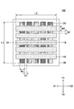
- FIG. 1 is a top view of the arrangement of the electrodes of the temperature sensor 100 in the present embodiment
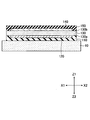
- FIG. 2 is a cross-sectional view of the temperature sensor 100 cut along a dashed dotted line 1A-1B in FIG.
- the temperature sensor 100 measures the temperature of the surface of the measurement object 10 to be measured, and the first insulating layer 110, the first electrode 120, the polymer layer 130, the second The electrode 140, the second insulating layer 150, and the like are stacked in the Z1 direction from the Z2 direction side.
- a plurality of first electrodes 120 are formed on one surface 130 a of the polymer layer 130 with a film of a conductive metal material such as copper (Cu), silver (Ag), ITO (Indium Tin Oxide), or the like. .
- the first electrode 120 is formed to be long in the Y1-Y2 direction, and for example, the adjacent first electrodes 120 have a width W1 of about 5 mm, a length L1 of about 30 mm, and a thickness t1 of 8 to 16 ⁇ m.
- the distance G1 between the first electrode 120 and the first electrode 120 is formed to be about 60 ⁇ m.
- a plurality of second electrodes 140 are formed on the other surface 130 b of the polymer layer 130 using a film of a conductive metal material or the like such as copper, silver, or ITO.
- the second electrode 140 is formed to be long in the X1-X2 direction, and for example, the adjacent second electrode 140 has a width W2 of about 5 mm, a length L2 of about 30 mm, and a thickness t2 of 8 to 16 ⁇ m.
- a gap G2 between the second electrode 140 and the second electrode 140 is formed to be about 60 .mu.m.
- the extending direction of the first electrode 120 and the extending direction of the second electrode 140 are orthogonal to each other.
- the distance between the adjacent first electrode 120 and the first electrode 120 is referred to as the distance between the electrodes of the first electrode 120, and the adjacent second electrode 140 and the second electrode 140 are described. May be described as the distance between the electrodes of the second electrode 140.
- the temperature sensor shown in FIG. 1 and FIG. 2 etc. five first electrodes 120 are provided, and five second electrodes 140 are provided.
- the first insulating layer 110 is formed of a flexible insulating resin material so as to cover the first electrode 120 formed on one surface 130 a of the polymer layer 130, and has a thickness, for example. Is formed of a 40 ⁇ m polyimide or the like.
- the second insulating layer 150 is formed of a flexible insulating resin material so as to cover the second electrode 140 formed on the other surface 130 b of the polymer layer 130, and has a thickness, for example. Is formed of a 40 ⁇ m polyimide or the like.
- the polymer layer 130 is formed of a resin material having flexibility in which the relative dielectric constant changes as the temperature changes. Specifically, it is formed of polyimide or the like having a thickness d of 50 ⁇ m or less.
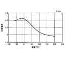
- FIG. 3 shows the relationship between the temperature and the relative dielectric constant of the polyimide when an alternating current of 1 kHz is applied. As shown in FIG. 3, when the temperature is -15.degree. C., the relative dielectric constant is about 3.45, and as the temperature rises, the relative dielectric constant gradually decreases, and when the temperature is 200.degree. C., the ratio is The dielectric constant is about 2.95.
- the linearity between the temperature and the relative dielectric constant will be described in the range of 20 ° C. to 100 ° C., which is relatively good.
- the relationship between the temperature and the relative dielectric constant is linear, and according to FIG. 3, the relative dielectric constant at a temperature of 20 ° C. is about 3.4, the temperature Assuming that the relative dielectric constant at 100 ° C. is about 3.1, the relative dielectric constant P is represented by the following equation (1).
- T is a temperature.
- the capacitance formed by the polymer layer 130 in a region sandwiched by the first electrode 120 and the second electrode 140 will be considered. Specifically, in a region where the first electrode 120 of width W1 where the first electrode 120 and the second electrode 140 intersect and the second electrode 140 of width W2 overlap, parallel plates at each intersection point If capacitors are to be formed, the area S of each parallel plate capacitor is 2.5 ⁇ 10 ⁇ 5 m 2 . In the examples shown in FIGS. 1 and 2, five first electrodes 120 and five second electrodes 140 are provided, and a total of 25 parallel plate capacitors are formed.
- the capacitance C at each intersection is expressed by the following equation (2).
- the vacuum dielectric constant ⁇ 0 is 8.85 ⁇ 10 12 .
- C P ⁇ ⁇ 0 ⁇ S / d (2)
- the relationship between the temperature and the capacitance when the thickness d of the polymer layer 130 is 12.5 ⁇ m (1.25 ⁇ 10 ⁇ 5 m) is shown in Table 2.
- the amount of change of the capacitance C at every 10 ° C. is about 0.66 pF (660 fF), and therefore, when the temperature changes by 1 ° C., The amount of change is about 66 fF. Since the resolution of the capacitance measuring device at present is 10 fF or more, the temperature resolution is about 0.15 ° C.
- the amount of change of the capacitance C at every 10 ° C. is about 0.33 pF (330 fF), and therefore, when the temperature changes by 1 ° C., The amount of change is about 33 fF.
- the resolution of the capacitance meter is the same as above, the resolution of the temperature is about 0.3.degree.
- the temperature resolution is about 0.6 ° C.
- the temperature resolution is about 0.9 ° C.
- the thickness d of the polymer layer 130 may be 75 ⁇ m considering that the temperature resolution is about 1 ° C., practically, the thickness d of the polymer layer 130 is 50 ⁇ m at which the temperature resolution is about 0.6 ° C or less It is preferable that it is the following.
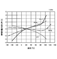
- FIG. 4 shows the relationship between the temperature and the rate of change of the capacitance measured by applying an alternating current of 1 kHz for PET, PEN, PP (Polypropylene), PPS (Poly Phenylene Sulfide), etc.
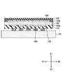
- the temperature sensor 100 in the present embodiment performs measurement by bringing the side of the first electrode 120 into contact with the surface of the measurement object 10 to be subjected to temperature measurement.
- the polymer layer 130, the first insulating layer 110, and the second insulating layer 150 are omitted in FIG. 5 for the sake of convenience, the omitted first insulating layer 110 is formed on the surface of the object 10 to be measured. Make contact and measure.
- the polymer layer 130, the first insulating layer 110, the second insulating layer 150, and the like are formed of a flexible material, and the first electrode 120 and the second electrode
- the electrode 140 is formed in a film shape and is extremely thin. For this reason, even if the surface of the measurement object 10 is not flat and is a curved surface or the like, it can be deformed according to the shape of the surface of the measurement object 10. Therefore, even when the surface of the measurement object 10 is a curved surface or the like, it can be brought into close contact and be in contact, and the temperature of the surface of the measurement object 10 can be measured accurately.
- the temperature measurement device in the present embodiment shown in FIG. 5 includes the temperature sensor 100, the temperature measurement unit 160, the display unit 170, and the like in the present embodiment.
- the temperature measurement unit 160 includes a capacitance detection unit 161, a calculation unit 162, a control unit 163, and the like.
- Each of the first electrode 120 and the second electrode 140 of the temperature sensor 100 is connected to the capacitance detection unit 161, and an alternating voltage is scanned and applied to the first electrode 120 and the second electrode.
- the capacitance formed between the first electrode 120 and the second electrode 140 is measured in each region where the electrodes 140 intersect with each other.
- the frequency of the alternating current applied when measuring the capacitance formed in each region of the temperature sensor 100 is preferably 1 kHz or more and 10 MHz or less.
- the calculation unit 162 calculates the temperature of each region based on the capacitance detection value in each region of the temperature sensor 100 detected by the capacitance detection unit 161.
- the control unit 163 controls the electrostatic capacitance detection unit 161 and the calculation unit 162, and the like.
- the display unit 170 is a display or the like capable of displaying a two-dimensional image, and can display information of temperature distribution in each region of the temperature sensor 100 obtained by the calculation unit 162 as a two-dimensional image.
- FIG. 6 shows a state in which the temperature distribution measured by the temperature sensor 100 in the present embodiment is displayed as a two-dimensional image on the display unit 170.
- FIG. 6 is a two-dimensional image of the temperature distribution obtained by the temperature sensor provided with five each of the first electrode 120 and the second electrode 140, but the first electrode 120 and the second electrode By increasing 140, more detailed two-dimensional temperature distribution information can be obtained.
- FIG. 7 shows a state of a two-dimensional image of a temperature distribution obtained by a temperature sensor provided with ten first electrodes 120 and ten second electrodes 140.
- the first electrode 120 and the second electrode 140 are formed of ITO or the like, and light is transmitted through the polymer layer 130, the first insulating layer 110, the second insulating layer 150, and the like. You may form with a material. In this case, since the surface of the measurement object 10 can be viewed through the temperature sensor, the temperature sensor can be easily attached to a desired position where the temperature of the surface of the measurement object 10 is to be measured.
- the temperature sensor measures the temperature by bringing the side of the first insulating layer 110 into contact with the surface of the measurement object 10, and therefore, between the first electrode 120 and the measurement object 10
- the first insulating layer 110 is preferably a material having a high thermal conductivity.
- the second insulating layer 150 is preferably formed of a material having a low thermal conductivity. Therefore, in the present embodiment, the first insulating layer 110 is preferably formed of a material having a thermal conductivity higher than that of the second insulating layer 150.
- thermal conductivity Materials that are flexible and have high thermal conductivity include heat-dissipating silicone rubber (thermal conductivity: 1 to 3 W / m ⁇ K) and thermally conductive double-sided adhesive tape (thermally conductive acrylic double-sided adhesive tape, thermally conductive Rate: 0.53 W / m ⁇ K) and the like.
- thermal conductivity of polyimide is about 0.16 W / m ⁇ K
- thermal conductivity of PET is about 0.14 W / m ⁇ K
- thermal conductivity of PEN is about 0.15 W / m ⁇ K.
- the first electrode 120 and the second electrode 140 are formed of copper having a thermal conductivity of 398 W / m ⁇ K, and the polymer layer 130 has a thermal conductivity of 0.16 W / m. It shall be formed of m ⁇ K polyimide. Therefore, the first electrode 120 and the second electrode 140 have a thermal conductivity of 2000 times or more that of the polymer layer 130.
- the distance G1 between the first electrodes 120 and the distance between the second electrodes 140 G2 is preferably formed wider than the thickness d of the polymer layer 130. If the distance G1 between the first electrodes 120 and the distance G2 between the second electrodes 140 are smaller than the thickness d of the polymer layer 130, the effect of the heat received from the adjacent region becomes large, and the temperature for each region That is, the temperature distribution can not be measured accurately.
- the first insulating layer 110 may be formed of a material having a thermal conductivity higher in the film thickness direction (Z1-Z2 direction) than in the in-plane direction (direction parallel to the XY plane).
- the in-plane direction is a direction perpendicular to the film thickness direction.
- thermal interference exerted on adjacent regions in the in-plane direction can be suppressed, and the heat transfer path can be divided for each region.
- a material is also called an anisotropic heat conductive material, and examples thereof include a graphite vertically oriented heat conductive sheet, and a material to which heat conductive anisotropy is imparted by controlling the structure of an organic polymer.
- the first insulating layer 110 may not be provided if the surface of the measurement target 10 to be subjected to the temperature measurement is an insulator. In the case where metal or the like is not expected to be in contact with the second electrode 140, the second insulating layer 150 may not be provided.
- the temperature sensor according to the present embodiment is formed of the first electrode 120, the polymer layer 130, and the second electrode 140, and the first electrode 120 is an object of temperature measurement. It may be in contact with the surface of the measurement object 10 to be
- the surface of the first insulating layer 110 that is, the side of the measurement object 10 causes the adhesive layer 180 to adhere to the surface of the measurement object 10. It may be provided on the surface of By forming such an adhesive layer 180, the temperature sensor can be brought into close contact with the surface of the measurement object 10 to be subjected to temperature measurement, and the temperature in each region can be accurately measured. That is, if there is a gap between the first insulating layer 110 and the surface of the measurement object 10, it is thermally insulated by the air existing in the gap, and the temperature of the surface of the measurement object 10 is accurately measured. Can not do it.
- the temperature sensor 100 can be adhered to the surface of the measurement object 10, and each region of the surface of the measurement object 10 It is possible to measure the exact temperature of The adhesive layer 180 may be integral with the first insulating layer 110.
- the adhesive layer 180 may, for example, be an acrylic double-sided adhesive tape or an acrylic double-sided adhesive tape of a PET substrate.
- a thermally conductive acrylic double-sided adhesive tape or the like having a thermal conductivity of 0.4 to 1.5 W / m ⁇ K may be used.
- the temperature sensor according to the present embodiment may have a pressure-sensitive adhesive layer 181 having insulation instead of the first insulating layer 110.
- the insulating adhesive layer 181 has both a function as an insulator and a function to be in close contact with the surface of the object to be measured 10.
- the adhesive layer 180 may be formed in a shape corresponding to the shape of the first electrode 120, and the shape of a region where the first electrode 120 and the second electrode 140 intersect. You may form in the shape corresponding to.
- thermal interference between adjacent regions can be further prevented.
- air is introduced between the adjacent adhesive layers 180 and thermally insulated, and therefore, they are also separated thermally.
- the size of the adhesive layer 180 may be smaller than the width of the first electrode 120, and the first electrode 120 and the second electrode 140 may be formed. You may form smaller than the area
- a third electrode 190 to be a shield electrode layer is formed of a material such as a metal on the second insulating layer 150, and the third electrode 190 is further formed.
- the third insulating layer 191 may be formed of a flexible and insulating resin material or the like so as to cover the electrode 190.
- the temperature sensor in the present embodiment is formed of the polymer layer 130 and the first electrode 120 and the second electrode 140 provided on both sides of the polymer layer 130, so that the temperature sensor can be miniaturized. It is possible and can be manufactured at low cost.
- the temperature sensor according to the present embodiment is not used for obtaining the temperature distribution of the surface of the measurement object 10, but as shown in FIG. 13 if it is simply used to measure the temperature of the surface of the measurement object 10.
- One each of the first electrode 120 and the second electrode 140 may be provided.
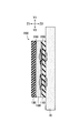
- FIG. 14 is a top view of the electrode arrangement of the temperature sensor 200 according to the present embodiment
- FIG. 14B is a cross-sectional view of the temperature sensor 200 taken along dashed dotted line 14A-14B in FIG. 14A
- 14C is a cross-sectional view of the temperature sensor 200 taken along dashed-dotted line 14C-14D in FIG. 14A.
- the temperature sensor 200 measures the temperature of the surface of the measurement object 10 to be subjected to the temperature measurement, and the first insulating layer 110, the first electrode 220, the polymer layer 130, the second The electrode 240, the second insulating layer 150, and the like are stacked in the Z1 direction from the Z2 direction side.
- the first electrode 220 and the second electrode 240 are formed of the same material as the first electrode 120 and the second electrode 140 in the first embodiment.
- a plurality of first electrodes 220 on the side of the measurement object 10 is formed, and the second electrode 220 on the opposite side to the side of the measurement object 10
- the one electrode 240 is formed so as to cover the entire first electrode 220.
- FIG. 15A is a top view of the electrode arrangement of the temperature sensor of this structure
- FIG. 15B is a cross-sectional view of the temperature sensor taken along dashed dotted line 15A-15B in FIG. 15A
- FIG. 15B is a cross-sectional view of the temperature sensor taken along dashed dotted line 15C-15D in FIG. 15A.
- the first electrode 920 and the second electrode 940 are formed of copper having a thermal conductivity of 398 W / m ⁇ K, and the polymer layer 130 is a polyimide having a thermal conductivity of 0.16 W / m ⁇ K. Shall be formed by Therefore, the first electrode 920 and the second electrode 940 have a thermal conductivity of 2000 times or more that of the polymer layer 130.
- the heat from the object to be measured 10 is transmitted to the first electrode 920 via the first insulating layer 110, as indicated by the dashed arrow.
- the first electrode 920 is formed of copper, the thermal conductivity is high, heat is transmitted in the in-plane direction, ie, in a direction parallel to the XY plane, and the entire surface of the first electrode 920 has substantially the same temperature. It will Since the first electrode 920 is formed over substantially the entire surface, the temperature of the entire polymer layer 130 is also substantially uniform, and the value of capacitance obtained through the plurality of second electrodes 940 is also substantially the same. It becomes. Therefore, in the temperature sensor having the structure shown in FIG. 15, even if the plurality of second electrodes 940 are provided, the detected temperatures are substantially the same, and the temperature distribution in each region of the surface of the measurement object 10 is measured You can not do it.
- the heat from the measurement object 10 is transferred to the first electrode 220 through the first insulating layer 110 as indicated by the dashed arrow. It is transmitted. Since the first electrode 220 is formed of copper, the thermal conductivity is high, but since the first electrode 220 is divided into a plurality of parts for each region, the temperature of the first electrode 220 is The temperature corresponds to the area. Therefore, since the temperature of the polymer layer 130 is also a temperature corresponding to each region of the first electrode 220, the value of the obtained capacitance is detected as a value reflecting the temperature distribution on the surface of the measurement object 10. Ru. Therefore, in the temperature sensor according to the present embodiment shown in FIG. 14, the temperature distribution on the surface of the measurement object 10 can be measured for each region of the plurality of first electrodes 220.
- the temperature sensor according to the present embodiment has a plurality of island-like regions in which the shapes of the first electrode and the second electrode are not strip-like and in which the temperature is measured, and connection regions connecting the island-like regions. It is formed by
- FIGS. 16 and 17 in the temperature sensor according to the present embodiment, a plurality of island regions 321 of the first electrode 320 are connected by the connection region 322, and the second electrode A plurality of island regions 341 are connected by a connection region 342.
- FIG. 16 is a view of the arrangement of the electrodes of the temperature sensor in the present embodiment from the top
- FIG. 17A is a view showing the arrangement of the first electrode 320
- FIG. Is a diagram showing the arrangement of FIG. 18 is a cross-sectional view taken along dashed dotted line 16A-16B in FIG.
- the first insulating layer 110, the first electrode 320, the polymer layer 130, the second electrode 340, the second insulating layer 150, and the like move in the Z1 direction from the Z2 direction. It is stacked.
- the first electrode 320 is a connection region 322 connecting the plurality of substantially square island regions 321 and the island regions 321 adjacent in the Y1-Y2 direction. And are formed.
- the size of the island-like region 321 of the first electrode 320 is a substantially square having a side length L11 of about 5 mm, and the island-like regions 321 adjacent in the Y1-Y2 direction are connected by the connection region 322 There is.
- the width L12 of the connection region 322 is narrower than the length L11 of one side of the island region 321, and is about 100 ⁇ m.
- the heat conduction in the connection region 322 becomes worse, so the thermal resolution in the adjacent island regions 321 can be improved. Accordingly, as shown in FIG. 17A, the island regions 321 adjacent in the Y1-Y2 direction are connected by the connection region 322, and five first electrodes 320 extending in the Y1-Y2 direction are provided.
- the second electrode 340 is formed of a plurality of substantially square island regions 341 and a connection region 342 connecting the island regions 341 adjacent in the X1-X2 direction. ing.
- the size of the island-like region 341 of the second electrode 340 is a substantially square having a side length L21 of about 5 mm, and the island-like regions 341 adjacent in the X1-X2 direction are connected by the connection region 342 There is.
- the width L22 of the connection region 342 is smaller than the length L21 of one side of the island region 341, and is about 100 ⁇ m.
- connection region 342 By narrowing the width L22 of the connection region 342, the heat conduction in the connection region 342 becomes worse, so the thermal resolution in the adjacent island regions 341 can be improved. Therefore, as shown in FIG. 17B, the island regions 341 adjacent in the X1-X2 direction are connected by the connection region 342, and five second electrodes 340 extending in the X1-X2 direction are provided.
- the island-like region 321 of the first electrode 320 and the island-like region 341 of the second electrode 340 are provided so as to overlap with each other. That is, in the present embodiment, the position of the insular region 321 of the first electrode 320 and the position of the insular region 341 of the second electrode 340 coincide in the X1-X2 direction and the Y1-Y2 direction, It is installed to overlap in the Z1-Z2 direction.
- a region is detected by detecting the capacitance of each region in which the polymer layer 130 is sandwiched between the island region 321 of the first electrode 320 and the island region 341 of the second electrode 340. Temperature measurement can be performed every time.
- thermal interference in each of the regions for detecting capacitance is formed by forming the narrow connection region 322 in the first electrode 320 and forming the narrow connection region 342 in the second electrode 340.
- the temperature distribution of the surface of the measurement object 10 can be accurately measured.
- FIG. 19 shows a temperature sensor according to the present embodiment, in which a first electrode 320 to which ten island regions 321 are connected and a second electrode 340 to which ten island regions 341 are connected are shown.
- the temperature sensor provided ten each, the result of having measured the temperature distribution of the surface of the measuring object 10 is shown typically.
- an adhesive layer 180 may be provided on the surface of the first insulating layer 110 to be in close contact with the surface of the object to be measured 10.
- the shape of the adhesive layer 180 is formed to be the same as or smaller than a region where the island-like region 321 of the first electrode 320 and the island-like region 341 of the second electrode 340 overlap. Furthermore, thermal interference can be suppressed.
- Measurement Object 100 Temperature Sensor 110 First Insulating Layer 120 First Electrode 130 Polymer Layer 130 a One Side 130 b Other Side 140 Second Electrode 150 Second Insulating Layer 160 Temperature Measurement Part 161 Capacitance Detection Part 162 operation unit 163 control unit 170 display unit 180 adhesive layer 190 third electrode 191 third insulating layer
Landscapes
- Engineering & Computer Science (AREA)
- Power Engineering (AREA)
- Physics & Mathematics (AREA)
- General Physics & Mathematics (AREA)
- Measuring Temperature Or Quantity Of Heat (AREA)
- Measuring And Recording Apparatus For Diagnosis (AREA)
- Radiation Pyrometers (AREA)
Abstract
Selon l'invention, un capteur de température est caractérisé en ce qu'il comprend une couche de polymère, une première électrode formée dans une surface de la couche polymère, et une deuxième électrode formée dans l'autre surface de la couche de polymère, où : la couche de polymère a une permittivité relative qui varie avec la température, et est composée d'un matériau souple; et le premier côté d'électrode est mis en contact avec un objet à mesurer de façon à mesurer la température de l'objet à mesurer en fonction de la capacité électrostatique de la couche de polymère dans une région prise en sandwich entre les première et deuxième électrodes.
Priority Applications (2)
| Application Number | Priority Date | Filing Date | Title |
|---|---|---|---|
| JP2019530892A JP6932782B2 (ja) | 2017-07-20 | 2018-05-09 | 温度センサ |
| US16/743,463 US11300459B2 (en) | 2017-07-20 | 2020-01-15 | Capacitive temperature sensor |
Applications Claiming Priority (2)
| Application Number | Priority Date | Filing Date | Title |
|---|---|---|---|
| US201762534745P | 2017-07-20 | 2017-07-20 | |
| US62/534,745 | 2017-07-20 |
Related Child Applications (1)
| Application Number | Title | Priority Date | Filing Date |
|---|---|---|---|
| US16/743,463 Continuation US11300459B2 (en) | 2017-07-20 | 2020-01-15 | Capacitive temperature sensor |
Publications (1)
| Publication Number | Publication Date |
|---|---|
| WO2019017045A1 true WO2019017045A1 (fr) | 2019-01-24 |
Family
ID=65015074
Family Applications (1)
| Application Number | Title | Priority Date | Filing Date |
|---|---|---|---|
| PCT/JP2018/017896 Ceased WO2019017045A1 (fr) | 2017-07-20 | 2018-05-09 | Capteur de température |
Country Status (3)
| Country | Link |
|---|---|
| US (1) | US11300459B2 (fr) |
| JP (1) | JP6932782B2 (fr) |
| WO (1) | WO2019017045A1 (fr) |
Cited By (3)
| Publication number | Priority date | Publication date | Assignee | Title |
|---|---|---|---|---|
| CN111537098A (zh) * | 2020-04-08 | 2020-08-14 | 中山大学 | 柔性电容式温度传感器及其制作方法 |
| KR20220012765A (ko) * | 2020-07-23 | 2022-02-04 | 광운대학교 산학협력단 | 헬스 케어 모니터링 시스템 구현을 위한 저전압, 고주파 영역에서 동작하는 금속 이온이 도핑된 고 유전율 산화물 절연체 기반의 웨어러블 온도 센서 |
| JPWO2024047925A1 (fr) * | 2022-09-01 | 2024-03-07 |
Citations (6)
| Publication number | Priority date | Publication date | Assignee | Title |
|---|---|---|---|---|
| JP2002111087A (ja) * | 2000-09-29 | 2002-04-12 | Matsushita Electric Ind Co Ltd | 可撓性圧電素子とそれを用いた異常監視装置 |
| JP2005172839A (ja) * | 2005-02-03 | 2005-06-30 | Matsushita Electric Ind Co Ltd | 温度測定システム |
| JP2005233708A (ja) * | 2004-02-18 | 2005-09-02 | Ishikawajima Harima Heavy Ind Co Ltd | 静電容量型荷重計 |
| JP2009192306A (ja) * | 2008-02-13 | 2009-08-27 | Wacom Co Ltd | 位置検出装置 |
| JP2010210400A (ja) * | 2009-03-10 | 2010-09-24 | Daikin Ind Ltd | 異常高温検出用素子、およびそれを備える異常高温検出用装置 |
| JP2015507185A (ja) * | 2012-01-02 | 2015-03-05 | コミッサリア ア レネルジー アトミーク エ オ ゼネルジ ザルタナテイヴ | 分圧器ブリッジとして2つのコンデンサを含む静電容量式温度センサ |
Family Cites Families (5)
| Publication number | Priority date | Publication date | Assignee | Title |
|---|---|---|---|---|
| US5021795A (en) * | 1989-06-23 | 1991-06-04 | Motorola, Inc. | Passive temperature compensation scheme for microstrip antennas |
| FI98567C (fi) * | 1993-09-29 | 1997-07-10 | Vaisala Oy | Impedanssianturi, etenkin radiosondikäyttöön, sekä menetelmä anturin valmistamiseksi |
| US6359444B1 (en) * | 1999-05-28 | 2002-03-19 | University Of Kentucky Research Foundation | Remote resonant-circuit analyte sensing apparatus with sensing structure and associated method of sensing |
| JP6026447B2 (ja) * | 2014-01-17 | 2016-11-16 | 富士フイルム株式会社 | タッチパネル用積層体、フラットパネルディスプレイ |
| JP2016091052A (ja) | 2014-10-29 | 2016-05-23 | 京セラ株式会社 | 電子機器 |
-
2018
- 2018-05-09 JP JP2019530892A patent/JP6932782B2/ja active Active
- 2018-05-09 WO PCT/JP2018/017896 patent/WO2019017045A1/fr not_active Ceased
-
2020
- 2020-01-15 US US16/743,463 patent/US11300459B2/en active Active
Patent Citations (6)
| Publication number | Priority date | Publication date | Assignee | Title |
|---|---|---|---|---|
| JP2002111087A (ja) * | 2000-09-29 | 2002-04-12 | Matsushita Electric Ind Co Ltd | 可撓性圧電素子とそれを用いた異常監視装置 |
| JP2005233708A (ja) * | 2004-02-18 | 2005-09-02 | Ishikawajima Harima Heavy Ind Co Ltd | 静電容量型荷重計 |
| JP2005172839A (ja) * | 2005-02-03 | 2005-06-30 | Matsushita Electric Ind Co Ltd | 温度測定システム |
| JP2009192306A (ja) * | 2008-02-13 | 2009-08-27 | Wacom Co Ltd | 位置検出装置 |
| JP2010210400A (ja) * | 2009-03-10 | 2010-09-24 | Daikin Ind Ltd | 異常高温検出用素子、およびそれを備える異常高温検出用装置 |
| JP2015507185A (ja) * | 2012-01-02 | 2015-03-05 | コミッサリア ア レネルジー アトミーク エ オ ゼネルジ ザルタナテイヴ | 分圧器ブリッジとして2つのコンデンサを含む静電容量式温度センサ |
Cited By (6)
| Publication number | Priority date | Publication date | Assignee | Title |
|---|---|---|---|---|
| CN111537098A (zh) * | 2020-04-08 | 2020-08-14 | 中山大学 | 柔性电容式温度传感器及其制作方法 |
| CN111537098B (zh) * | 2020-04-08 | 2021-07-13 | 中山大学 | 柔性电容式温度传感器及其制作方法 |
| KR20220012765A (ko) * | 2020-07-23 | 2022-02-04 | 광운대학교 산학협력단 | 헬스 케어 모니터링 시스템 구현을 위한 저전압, 고주파 영역에서 동작하는 금속 이온이 도핑된 고 유전율 산화물 절연체 기반의 웨어러블 온도 센서 |
| KR102424918B1 (ko) * | 2020-07-23 | 2022-07-25 | 광운대학교 산학협력단 | 헬스 케어 모니터링 시스템 구현을 위한 저전압, 고주파 영역에서 동작하는 금속 이온이 도핑된 고 유전율 산화물 절연체 기반의 웨어러블 온도 센서 |
| JPWO2024047925A1 (fr) * | 2022-09-01 | 2024-03-07 | ||
| JP7740565B2 (ja) | 2022-09-01 | 2025-09-17 | 株式会社デンソー | 電池ユニット、電池監視装置及びプログラム |
Also Published As
| Publication number | Publication date |
|---|---|
| JPWO2019017045A1 (ja) | 2020-07-02 |
| US20200149978A1 (en) | 2020-05-14 |
| US11300459B2 (en) | 2022-04-12 |
| JP6932782B2 (ja) | 2021-09-08 |
Similar Documents
| Publication | Publication Date | Title |
|---|---|---|
| JP6562357B2 (ja) | 感圧センサ | |
| US9222846B2 (en) | Tactile sensor | |
| Sheng et al. | Liquid-metal-painted stretchable capacitor sensors for wearable healthcare electronics | |
| JP6932782B2 (ja) | 温度センサ | |
| US10553655B2 (en) | Force sensor device and OLED display device including the same | |
| CN107110716B (zh) | 传感器片 | |
| US10591523B2 (en) | Capacitive sensor and manufacturing method thereof | |
| JP2013020370A5 (fr) | ||
| US8393209B2 (en) | Capacitive detector, method for manufacturing same, and device for measuring the integral | |
| JP6468398B2 (ja) | 深部体温計 | |
| JP7205770B2 (ja) | 複合センサ | |
| JP2015513068A (ja) | 熱画像センサ | |
| TWI565934B (zh) | 感測器 | |
| Kim et al. | A flexible skin piloerection monitoring sensor | |
| Park et al. | Pixel-free capacitive touch sensor using a single-layer ion gel | |
| KR100990087B1 (ko) | 유연성 박막 어레이형 온도센서 및 그 제조방법 | |
| US10591360B2 (en) | Thermal sensor with two superposed pyroelectric portions for measuring a charge differential | |
| KR101530189B1 (ko) | 복수의 막대형 투명 전극을 구비한 터치스크린 장치 | |
| JP7152708B2 (ja) | 静電容量型センサ | |
| JP2020016484A (ja) | 温度センサ | |
| GB2522639A (en) | An apparatus and associated methods for temperature sensing | |
| WO2015025487A1 (fr) | Écran tactile | |
| CN112179517A (zh) | 温度传感器以及温度检测方法 | |
| JP3161093U (ja) | 折り返し導体を有する導電膜フィルムヒーター | |
| CN113120851B (zh) | 具有气密空腔的微机电装置 |
Legal Events
| Date | Code | Title | Description |
|---|---|---|---|
| 121 | Ep: the epo has been informed by wipo that ep was designated in this application |
Ref document number: 18835136 Country of ref document: EP Kind code of ref document: A1 |
|
| ENP | Entry into the national phase |
Ref document number: 2019530892 Country of ref document: JP Kind code of ref document: A |
|
| NENP | Non-entry into the national phase |
Ref country code: DE |
|
| 122 | Ep: pct application non-entry in european phase |
Ref document number: 18835136 Country of ref document: EP Kind code of ref document: A1 |