WO2019017187A1 - Visiocasque - Google Patents
Visiocasque Download PDFInfo
- Publication number
- WO2019017187A1 WO2019017187A1 PCT/JP2018/024907 JP2018024907W WO2019017187A1 WO 2019017187 A1 WO2019017187 A1 WO 2019017187A1 JP 2018024907 W JP2018024907 W JP 2018024907W WO 2019017187 A1 WO2019017187 A1 WO 2019017187A1
- Authority
- WO
- WIPO (PCT)
- Prior art keywords
- head
- display
- head mounted
- user
- mounted display
- Prior art date
- Legal status (The legal status is an assumption and is not a legal conclusion. Google has not performed a legal analysis and makes no representation as to the accuracy of the status listed.)
- Ceased
Links
Images




Classifications
-
- G—PHYSICS
- G02—OPTICS
- G02B—OPTICAL ELEMENTS, SYSTEMS OR APPARATUS
- G02B27/00—Optical systems or apparatus not provided for by any of the groups G02B1/00 - G02B26/00, G02B30/00
- G02B27/01—Head-up displays
- G02B27/017—Head mounted
- G02B27/0172—Head mounted characterised by optical features
-
- G—PHYSICS
- G02—OPTICS
- G02B—OPTICAL ELEMENTS, SYSTEMS OR APPARATUS
- G02B27/00—Optical systems or apparatus not provided for by any of the groups G02B1/00 - G02B26/00, G02B30/00
- G02B27/01—Head-up displays
- G02B27/017—Head mounted
- G02B27/0176—Head mounted characterised by mechanical features
-
- H—ELECTRICITY
- H04—ELECTRIC COMMUNICATION TECHNIQUE
- H04N—PICTORIAL COMMUNICATION, e.g. TELEVISION
- H04N5/00—Details of television systems
- H04N5/64—Constructional details of receivers, e.g. cabinets or dust covers
-
- G—PHYSICS
- G02—OPTICS
- G02B—OPTICAL ELEMENTS, SYSTEMS OR APPARATUS
- G02B27/00—Optical systems or apparatus not provided for by any of the groups G02B1/00 - G02B26/00, G02B30/00
- G02B27/01—Head-up displays
- G02B27/0179—Display position adjusting means not related to the information to be displayed
- G02B2027/0181—Adaptation to the pilot/driver
Definitions
- the present disclosure relates to a head mounted display.
- VR head mounted displays that support VR (Virtual Reality) have become widespread.
- the VR head mounted display is used for games executed in virtual reality, sports, live watching, and the like.
- the VR head mounted display is mounted on the head of the user, detects the position or direction of the user, and displays an image according to the detected position or direction.
- Such a head mounted display has a type having two display devices for displaying different images for the right eye and for the left eye, and a display device for displaying one image common to the right eye and the left eye.
- the center of gravity of the head mounted display will be located forward.
- the user when the user is a child who does not have sufficient head and neck muscle strength, the user needs to manually support the head mounted display, and there is a problem that the feeling of immersion is reduced.
- Patent Document 1 a hat-shaped virtual reality display image including an attachment hole on the upper surface of the eaves of the hat, an image display provided inside the attachment hole, and a reflecting mirror for reflecting an image of the image display on the lower surface of the eaves.
- a system is disclosed.
- the present embodiment has been made to solve such a problem, and in a head mounted display using a reflecting member, maintaining the sense of immersion of the user and improving the stability of the display device and the reflecting member. With the goal.
- the head mounted display includes a holding unit, a mounting member mounted on the head of the user, whose length is adjusted according to the size of the head, and a display surface for displaying an image
- the display device is held by the holder so as to face downward with the mounting member mounted on the head of the user, and is held by the holder so that the reflective surface faces the display surface side of the display device.
- a reflecting member that reflects the light toward the eye of the user whose mounting member is mounted on the head, and a shielding unit that shields a space in which the display device and the reflecting member are provided.
- the reflecting member is preferably disposed in front of the face of the user wearing the mounting member.
- the reflection member is held by the holding portion such that the surface opposite to the reflection surface abuts on the holding portion.
- the display device is preferably held at a portion of the holding portion which is disposed above the head of the user who has mounted the mounting member.
- the shielding portion is preferably provided so as to surround the back of the head of the user wearing the mounting member.
- the shielding portion is preferably provided to cover a part of the side end of the mounting member.
- the holding portion is provided with a weighting member for positioning the center of gravity of the head mounted display in a region on the top of the head of the user who wears the mounting member from the portion where the display device is held. Is preferred.
- the head mount display further includes a lens provided between the display device and the reflecting member to magnify the image.
- the head mounted display further includes a sensor for acquiring position and direction information of the head mounted display, and the display device displays an image according to the position and direction information.
- the display unit has a holding portion, a display surface for displaying an image, and a holding surface held by the holding portion, and a reflective surface is on the display surface side of the display device. It has a reflecting member held by the holding portion so as to face, and a shielding portion which shields the space provided with the display device and the reflecting member.
- the head mounted display using the reflective member it is possible to maintain the immersion feeling of the user and to improve the stability of the display device and the reflective member.
- FIG. 1 is a diagram showing an example of a schematic configuration of a head mounted display 1; (A), (B) is a typical perspective view of the head mounted display 1.
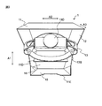
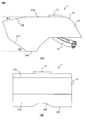
- FIG. FIG. 1 is a schematic perspective view of a head mounted display 1; (A) is a side view of the head mounted display 1, (B) is a front view of the head mounted display 1. (A), (B) is the top view and bottom view of the head mounted display 1.
- FIG. FIG. 2 is a schematic view for explaining an internal structure of the head mounted display 1;
- FIG. 2 is a diagram showing an example of a schematic configuration of a control device 2.
- FIG. 2 is a schematic perspective view of a head mounted display 3;
- FIG. 2 is a schematic perspective view of a head mounted display 4;
- FIG. 2 is a schematic perspective view of a head mounted display 5;
- FIG. 1 is a diagram showing an example of a schematic configuration of a game system 100.
- FIG. 2 is a diagram showing an example of a schematic configuration
- FIG. 1 is a view showing an example of a schematic configuration of the head mounted display 1.
- the head mounted display 1 includes a holding unit 11, a shielding unit 12, a mounting member 13, a display device 14, a reflecting member 15 and the like.
- the holding unit 11 holds the mounting member 13, the display device 14, and the reflecting member 15 on the inside thereof.
- the shielding unit 12 is provided in the holding unit 11 so as to shield the space in which the display device 14 and the reflecting member 15 are provided together with the holding unit 11.
- the mounting member 13 is mounted on the head of the user, and is held by the holder 11 so that the length is adjusted in accordance with the size of the head.
- the display device 14 is held by the holding unit 11 so that the display surface for displaying an image faces downward with the mounting member 13 mounted on the head of the user.
- the reflection member 15 is held by the holding unit 11 so that the reflection surface faces the display surface side of the display device 14, and reflects the image displayed on the display device 14 toward the eyeballs of the user.
- the holding unit 11 and the shielding unit 12 shield the external light, so it is possible to maintain the user's sense of immersion. Further, in the head mounted display 1, the mounting member 13, the display device 14 and the reflection member 15 are held inside the one holding portion 11, so the stability of the display device 14 and the reflection member 15 with respect to the user's head is improved. It is possible to
- the size or position of the rear end of the holding portion 11 is set (adjusted) so that the center of gravity is located within a predetermined range from the user's head.
- the user can easily hold the head mounted display 1.
- FIGS. 2A, 2B, and 3 are schematic perspective views of the head mounted display 1 according to the present embodiment.
- FIG. 2A is a perspective view of the head mount display 1 as viewed obliquely from above
- FIG. 2B is a perspective view of the head mount display 1 as viewed obliquely from below
- FIG. 3 is a head mount
- FIG. 2 is a perspective view of the display 1 as viewed from below.
- the head mounted display 1 is a VR head mounted display that displays one image common to the right eye and the left eye, and is used for a game executed in virtual reality, sports, live watching, and the like.
- the head mounted display 1 may be used for uses other than VR (such as viewing of a general image).
- the head mounted display 1 includes a holding unit 11, a shielding unit 12, a mounting member 13, a display device 14, a reflecting member 15, a lens 16, and a sensor 17. Etc.
- the holding unit 11 is formed to cover the head of the user wearing the head mount display 1 from the front to the back, and holds the mounting member 13, the display device 14, the reflecting member 15, the lens 16 and the like inside.
- the holding portion 11 is formed to be bent so as to cover from the user's eyes to the back of the head through the top of the head.
- the inner surface of the holding portion 11 has a low reflectance.
- the holding portion 11 is formed of a material having a low reflectance.
- the inner surface of the holding portion 11 may be applied in black.
- the holding portion 11 holds the mounting member 13 at a first portion 11A which is located at the center in the front-rear direction A1 and located on the upper side in the height direction A3.
- the holding portion 11 holds the display device 14 in the second portion 11B (the front side of the first portion 11A) positioned on the front side in the longitudinal direction A1 and on the upper side in the height direction A3.
- the second portion 11B is an example of a portion disposed above the head of the user wearing the mounting member 13.
- the inner surface (the second portion 11B) of the holding portion 11 may be provided with an attaching / detaching mechanism for disposing the display device 14 in a detachable manner.
- the holding portion 11 holds the reflecting member 15 at a third portion 11C (lower side of the second portion 11B) positioned on the front side in the longitudinal direction A1 and on the lower side in the height direction A3.
- a support member 11D is provided inside the holding portion 11.
- the support member 11D is provided downward from the upper surface of the holding portion 11, supports one end of the lens 16 on one side, and supports the mounting member 13 on the other side.
- a buffer member such as a rubber member or a flexible polyurethane foam may be provided at the lower end 11E of the third portion 11C.
- the lower end 11E of the third portion 11C is disposed so as not to be in contact with the user's face. Even if the lower end 11E contacts the face of the user, the rubber member is less likely to adhere with sweat or sebum as compared to the sponge member etc., so that the head mounted display 1 can be kept clean Become.
- the buffer member may be provided so as to extend toward the inside (face side of the user) of the head mounted display 1.
- the shielding unit 12 is provided on the side of the holding unit 11 so as to cover the side of the head of the user wearing the head mounted display 1.
- the inner surface of the shielding portion 12 has a low reflectance like the inner surface of the holding portion 11.
- the shielding unit 12 is formed of a material having a low reflectance.
- the inner surface of the shield 12 may be applied in black.
- an opening is provided on the opposite side to the first portion 11A of the holding portion 11, and the user mounts and dismounts the head mount display 1 through the opening. be able to.
- the mounting member 13 is a member for mounting on the head of the user and fixing the head of the user.
- the mounting member 13 is held inside the first portion 11A of the holder 11, that is, above the holder 11, so as to be mounted on the head of the user.
- the mounting member 13 has a first mounting portion 13A mounted on the top of the head of the user, a second mounting portion 13B mounted on the forehead of the user, and a third mounting portion 13C mounted on the back of the user's head , And are configured to be worn on the user's forehead, head of the head and back of the head.
- the mounting member 13 also has an adjustment dial 13D for adjusting the length of the third mounting portion 13C in accordance with the size of the head of the user. The user can fit the mounting member 13 appropriately to the head by adjusting the length of the third mounting portion 13C using the adjustment dial 13D.
- the mounting member 13 is formed of a rubber member or a resin member. 2. Description of the Related Art Conventionally, a head mounted display of a type having a main body portion that abuts on the periphery of a user's eyes is mainly used. This type of head mounted display is mounted on the user's head by tightening a belt connected to the body. In this case, a sponge member or the like is provided at the contact position with the user in order to relieve pressure on the periphery of the user's eyes.
- the mounting member 13 is mounted on the user's forehead, top of the head and back of the head, even if the rubber member or resin member directly contacts the user instead of the sponge member, the user feels pressure enough to feel around the eyes I do not feel Even if the rubber member or the resin member comes in contact with the user's face or head, it is difficult to adhere sweat or sebum etc. as compared with the sponge member etc., so that the head mount display 1 is kept clean. Is possible.
- the display device 14 is a display that displays an image.
- the display device 14 has a display surface for displaying an image and a holding surface held by the holding unit 11.
- the display device 14 is held inside the second portion 11B of the holding portion 11 and in front of the mounting member 13 so as to display an image toward the inside (downward) of the holding portion 11.
- a liquid crystal display, an organic EL (Electro-Luminescence) display, or the like is used.
- a multi-function mobile phone so-called “smart phone”
- a tablet PC Personal Computer
- the reflecting member 15 is held by the holding unit 11 so that the reflecting surface faces the display surface side of the display device 14, and the image displayed on the display device 14 is directed to the eyeball of the user wearing the mounting member 13 on the head.
- Reflection mirror The reflecting member 15 is disposed in front of the face of the user wearing the mounting member 13 and is held inside the third portion 11C of the holding portion 11, that is, below the holding portion 11 so as to face the display device 14. That is, the reflection member 15 is held by the holding portion 11 so that the surface opposite to the reflection surface abuts on the holding portion 11. It is preferable that a plastic mirror with less risk of breakage be used as the reflecting member 15. A paper mirror may be used as the reflection member 15. In addition, a plurality of reflecting members 15 may be provided in the light path from the display device 14 to the eyeball of the user.
- the lens 16 is provided between the display device 14 and the reflective member 15 and optically magnifies the image displayed on the display device 14 when viewed from the reflective member 15 side.
- the lens 16 is disposed such that one end is supported by the upper end of the third portion 11C and the other end is supported by the support member 11D.
- the lens 16 is, for example, a convex Fresnel lens having a predetermined magnification (for example, 6 times).
- a plurality of lenses 16 may be provided between the display device 14 and the reflecting member 15. Also, one or more lenses may be provided between the reflecting member 15 and the eye position of the user.
- the sensor 17 is a position tracking device that acquires position or orientation information of the head mounted display 1.
- the sensor 17 includes a light receiving unit provided outside which receives a laser from an irradiating unit that emits a laser, and calculates position information based on light received by the light receiving unit.
- the sensor 17 has a 3-axis acceleration sensor that detects the acceleration applied to the head mount display 1 in each of the 3-axis directions, and calculates position information of the head mount display 1 from each acceleration detected by the 3-axis acceleration sensor. It is also good.
- the sensor 17 also has a three-axis gyro sensor that detects the rotational angular velocity of the head mounted display 1 every three axial directions, and calculates direction information of the head mounted display 1 from each rotational angular velocity detected by the three axis gyro sensor. .
- the sensor 17 may be anything as long as it can acquire position or direction information, and is not limited to the above-described configuration.
- FIG. 4A is a side view of the head mounted display 1.
- the shielding portion 12 is formed such that the upper end (the end in contact with the first portion 11A of the holding portion 11) and the lower end 12A are substantially parallel.
- the upper end and the lower end 12A of the shielding portion 12 are used in a substantially horizontal state.
- the second portion 11B of the holding portion 11, that is, the display device 14 is provided so as to be inclined downward at a first angle ⁇ 1 with respect to the upper end of the shielding portion 12.
- the first angle ⁇ 1 is set to an angle (for example, 10 °) larger than 0 ° and smaller than 20 °.
- the third portion 11C of the holding portion 11, that is, the reflection member 15 is provided to be inclined upward by the second angle ⁇ 2 with respect to the lower end 12A of the shielding portion 12.
- the second angle ⁇ 2 is set to an angle of, for example, 30 ° or more and 50 ° or less (for example, 35 °).
- an acute angle is set to be larger than 30 ° and smaller than 70 °. More preferably, it is set to 40 degrees or more and 60 degrees or less, and more preferably set to 40 degrees or more and 50 degrees or less.
- the second angle ⁇ 2 is made too large, the face of the user who wears the head mounted display 1 may be reflected in the reflecting member 15.
- the first angle ⁇ 1 and the second angle ⁇ 2 as described above, the face of the user who wears the head mounted display 1 is reflected in the reflecting member 15 while suppressing the increase in the size of the head mounted display 1 It becomes possible to prevent that.
- FIG. 4B is a front view of the head mounted display 1.
- a notch 11F is formed at the lower end 11E of the third portion 11C of the holder 11 so that the user's nose does not contact the holder 11.
- the size of the reflecting member 15 increases as the distance between the reflecting member 15 and the eye of the user wearing the mounting member 13 increases. There is a need to. As the size of the reflecting member 15 increases, the size of the head mounted display 1, in particular the space in front of the user, increases. Therefore, it is desirable that the distance between the reflecting member 15 and the eyeball of the user wearing the mounting member 13 be small. In the head mounted display 1, the notch 11 F makes it possible to reduce the distance between the reflecting member 15 and the eye of the user wearing the mounting member 13, thereby reducing the size of the head mounted display 1. It becomes possible.
- 5A and 5B are a plan view and a bottom view of the head mounted display 1, respectively.
- the sensor 17 is disposed at a position facing the first mounting portion 13A of the mounting member 13 via the first portion 11A of the holder 11. As a result, the sensor 17 is disposed at a position facing the top of the head of the user who wears the head mounted display 1, and the center of gravity of the head mounted display 1 can be located closer to the top of the head of the user. Therefore, the user can easily hold the head mounted display 1.
- FIG. 6 is a schematic view for explaining the internal structure of the head mounted display 1.
- the display device 14 is disposed so that the display surface faces downward and displays an image
- the reflection member 15 directs the reflection surface to the display surface side of the display device 14 to display the image on the display device 14.
- the displayed image is arranged to be reflected toward the eye of the user wearing the mounting member 13.
- the lens 16 is disposed between the display device 14 and the reflective member 15 so as to optically magnify the image displayed on the display device 14 toward the reflective member 15. Therefore, the image displayed on the display device 14 is magnified by the lens 16 and reflected by the reflecting member 15 to reach the eyes of the user.
- the display device 14 is disposed near or above the top of the head of the user wearing the mounting member 13 so that the display surface is directed downward.
- the head mount display 1 disperses the load as compared with the case where the display device 14 is disposed in front of the eyeball of the user in a posture of the display surface facing the face of the user, and the head It is possible to position the center of gravity of the mount display 1 rearward (to the user's head). Therefore, the user can easily hold the head mounted display 1.
- the image displayed on the display device 14 reaches the eyeball of the user via the reflecting member 15.
- the head mounted display 1 can cause an image displayed on the display device 14 disposed above the user to reach the eye of the user.
- the distance from the display position 14 to the user's eye is the distance from the display position 14 to the reflecting member 15 and the distance from the reflecting member 15 to the user's eye It will be the sum of distances.
- the distance from the display position 14 to the user's eyes can be sufficiently increased, and it is possible to prevent the user from becoming blind and making it difficult to view the display 14.
- the image displayed on the display device 14 reaches the eyeball of the user via the lens 16.
- the head mounted display 1 it is possible to increase the range of the image (FOV: Field Of View) occupied by the user's field of view without increasing the size of the display device 14. Therefore, the head mounted display 1 can maintain the immersion feeling of the user without increasing the size (weight).
- the lens 16 may be omitted, and instead a magnifying glass may be used as the reflecting member 15. Also in this case, the head mounted display 1 can maintain the immersion feeling of the user.
- the lens 16 is formed so that the upper end (the end in contact with the first portion 11A of the holding portion 11) and the lower end 12A are substantially parallel. Thereby, the image displayed on the display device 14 is enlarged without distortion.
- a half mirror that transmits light from the display device 14 and does not transmit light from the reflective member 15 may be provided below the lens 16. This prevents external light from being reflected by the display device 14 and reflected to the eyes of the user.
- the holding portion 11 and the shielding portion 12 are formed so as to be flat (there is no convex portion) between the display device 14 and the lens 16 and between the lens 16 and the reflecting member 15. This prevents the image displayed on the display device 14 from being shielded and the holding portion 11 from being reflected in the reflection member 15.
- the support member 11D is provided to be orthogonal to the first portion 11A.
- the fourth portion 11H between the second portion 11B holding the display device 14 and the third portion 11C holding the reflection member 15 is such that the upper side is inclined forward with respect to the support member 11D.
- the shielding portion 12 is provided so as to cover a part or all of the side end of the mounting member 13 and the display device 14 and the reflecting member 15, and a space where the display device 14 and the reflecting member 15 are provided together with the holding portion 11.
- the shielding part 12 is provided so that the occipital region of the user who mounted
- the shielding unit 12 shields the inside of the head mounted display 1, particularly the entrance of external light to the eyeball of the user wearing the mounting member 13. Since the user does not look at the image outside the head mounted display 1 when the head mounted display 1 is attached, the user can maintain an immersive feeling to the image displayed on the display device 14.
- the center of gravity of the head mount display 1 is in the horizontal direction from the top of the head P1 of the user with the mounting member 13 mounted on the head (a position where the first mounting unit 13A abuts the holding unit 11). It is formed within a predetermined range R (for example, 5 cm) and located inside the head mounted display 1 in the vertical direction.
- the center of gravity of the head mounted display 1 is a midpoint between the two left and right combined positions P2 of the first mounting unit 13A, the second mounting unit 13B, and the third mounting unit 13C in the horizontal direction. , And may be located inside the head mounted display 1 in the vertical direction.
- the size or position of the rear end 11 ⁇ / b> G of the holder 11 is set (adjusted) such that the center of gravity is located within a predetermined range from the top of the head of the user.
- the rear end 11G is formed large so as to balance the front and back with the display device 14, the reflection member 15, and the lens 16 disposed in front with the user's head at the center. Ru.
- the rear end 11 ⁇ / b> G may be formed rearward so as to balance front and back.
- the center of the head mount display 1 at the rear end portion 11G of the holding portion 11 and the area on the parietal side of the user wearing the mounting member 13 from the portion where the display device 14 is held A weighting member may be provided for positioning inward.
- an audio output device such as a headphone that outputs an audio corresponding to an image displayed on the display device 14 may be provided at the rear end portion 11G of the holding unit 11 as a weighting member.
- FIG. 7 is a diagram showing an example of a schematic configuration of the control device 2.
- the control device 2 includes an interface unit 21, a storage unit 22, and a processing unit 23.
- the control device 2 is communicably connected to the sensor 17 and the display device 14, and changes the image displayed on the display device 14 according to the detection result of the sensor 17.
- the control device 2 is connected to the sensor 17 and the display device 14 via a cable or a wireless communication network (not shown), and is disposed at a position away from the head mounted display 1.
- the control device 2 may be disposed on the holder 11 of the head mounted display 1.
- the control device 2 may be incorporated in the display device 14.
- the interface unit 21 has an interface circuit conforming to a serial bus such as USB (Universal Serial Bus), for example, and is electrically connected to the sensor 17 and the display device 14 to transmit and receive images and various information. Further, the interface unit 21 has an antenna for transmitting and receiving a wireless signal, and a wireless communication interface circuit for transmitting and receiving a signal through a wireless communication line according to a predetermined communication protocol such as a wireless LAN (Local Area Network). You may connect with the sensor 17 and the display apparatus 14 by wireless communication.
- a serial bus such as USB (Universal Serial Bus)
- a wireless communication interface circuit for transmitting and receiving a signal through a wireless communication line according to a predetermined communication protocol such as a wireless LAN (Local Area Network). You may connect with the sensor 17 and the display apparatus 14 by wireless communication.
- the storage unit 22 includes, for example, a semiconductor memory such as a volatile memory or a non-volatile memory.
- the storage unit 22 stores an operating system program, a driver program, an application program, data, and the like used for processing in the processing unit 23.
- the computer program is stored in a storage unit 22 using a known setup program or the like from a computer-readable portable recording medium such as a compact disk read only memory (CD-ROM) or a digital versatile disk read only memory (DVD-ROM). May be installed on
- the computer program may be installed in the storage unit 22 from a specific server device or the like via wireless communication.
- the storage unit 22 stores, as data, image (moving image or still image) data and the like to be displayed on the display device 14.
- the storage unit 22 may temporarily store temporary data related to a predetermined process.
- the processing unit 23 includes one or more processors and their peripheral circuits.
- the processing unit 23 is, for example, a central processing unit (CPU), and centrally controls the overall operation of the control device 2.
- the processing unit 23 may be a digital signal processor (DSP), a large scale integration (LSI), an application specific integrated circuit (ASIC), a field-programming gate array (FPGA), or the like.
- DSP digital signal processor
- LSI large scale integration
- ASIC application specific integrated circuit
- FPGA field-programming gate array
- the processing unit 23 controls the operation of the interface unit 21 and the like so that various processes of the control device 2 are executed in an appropriate procedure based on a program or the like stored in the storage unit 22.
- the processing unit 23 executes processing based on a program (an operating system program, a driver program, an application program, etc.) stored in the storage unit 22.
- the processing unit 23 acquires position information and direction information of the head mounted display 1 from the sensor 17 via the interface unit 21.
- the processing unit 23 reads an image to be displayed on the display device 14 from the storage unit 22 and generates an image according to the acquired position information and direction information from the read image.
- the processing unit 23 causes the display device 14 to display the generated image via the interface unit 21. Note that the processing unit 23 generates an image that is horizontally or vertically reversed as necessary so that the image displayed on the display device 14 appears in the correct direction for the user's eyes.
- the holding unit 11 and the shielding unit 12 shield the space in which the display device 14 and the reflecting member 15 are provided and shield the external light, so the user is immersive. It becomes possible to maintain. Further, in the head mounted display 1, the mounting member 13, the display device 14 and the reflection member 15 are held inside the one holding portion 11, so the stability of the display device 14 and the reflection member 15 with respect to the user's head is improved. It is possible to
- the head mounted display 1 arranges the display 14 above the head of the user, and reflects the image displayed on the display 14 toward the eye of the user by the reflecting member 15. As a result, the head mounted display 1 can position the center of gravity rearward (to the top of the head of the user). Therefore, the user can wear the head mounted display 1 without supporting the head mounted display 1 by hand, even for a child or the like who does not have sufficient head and neck muscle strength.
- FIG. 8 is a schematic perspective view of a head mounted display 3 according to another embodiment.
- FIG. 8 is a perspective view of the head mounted display 3 as viewed from below.
- the head mounted display 3 shown in FIG. 8 has the same configuration as the head mounted display 1. However, in the head mounted display 3, the adjustment dial 13D for adjusting the length of the third mounting portion 13C is omitted, and instead, the third mounting member 33C is formed of an elastic member such as a rubber belt. This allows the user to fit the mounting member 33 properly to the head by means of the elastic member. Further, the head mounted display 3 can also achieve the same effect as the head mounted display 1.
- FIG. 9 is a schematic perspective view of a head mounted display 4 according to still another embodiment.
- FIG. 9 is a perspective view of the head mounted display 4 as viewed obliquely from above.
- the head mounted display 4 shown in FIG. 9 has the same configuration as the head mounted display 1. However, in the head mounted display 4, the mounting member 13, the display device 14, the reflecting member 15, and the lens 16 are held by the rod-shaped holding portion 41 instead of the plate-shaped holding portion 11.
- the holding portion 41 has a first portion 41A and a second portion 41B provided at both ends in the left-right direction A2, and a third portion 41C connecting the first portion 41A and the second portion 41B.
- a shielding part 42A covering the side of the holding part 41 and a shielding part 42B covering the front of the holding part 41 are provided.
- the head mounted display 4 can also achieve the same effect as the head mounted display 1.
- FIG. 10 is a schematic perspective view of a head mounted display 5 according to still another embodiment.
- FIG. 10 is a perspective view of the head mounted display 5 as viewed obliquely from above.
- the head mounted display 5 shown in FIG. 10 has the same configuration as the head mounted display 1. However, in the head mount display 5, the mounting member 13, the display device 14, the reflecting member 15, and the lens 16 are held by the rod-shaped holding portion 51 instead of the plate-shaped holding portion 11.
- the holding portion 41 is provided at a central position in the left-right direction A2. Further, in the head mounted display 5, instead of the shielding part 12 covering the side of the holding part 11, a shielding part 52A covering the side of the holding part 51 and a shielding part 52B covering the front of the holding part 51 are provided.
- the head mounted display 5 can also achieve the same effect as the head mounted display 1.
- the present disclosure is not limited to the present embodiment.
- the holding portion 11 and the shielding portion 12 may be formed of the same member.
- the holding unit 11 and the shielding unit 12 may be part of a cap attached to the head of the user.
- the cap body has, for example, a helmet shape.
- a main body including the holding unit 11, the shielding unit 12, the display device 14, and the reflecting member 15 may be provided rotatably with respect to the mounting member 13.
- the main body unit accommodates the display device 14 and the reflection member 15 in the space formed by the holding unit 11 and the shielding unit 12.
- the main body portion is connected to the mounting member 13 via a rotation shaft member so as to be able to rotate in the supine angle direction with respect to the mounting member 13. This makes it possible to arrange the display device 14 and the reflection member 15 at an appropriate position according to the individual difference between users.
- FIG. 11 is a view showing an example of a schematic configuration of a game system 100 to which a head mounted display 6 according to still another embodiment is applied.
- the game system 100 includes a base 101, a chair 102, an input device 103, and the like.
- the base 101 is provided to be fixed to a floor surface or the like.
- the chair 101 is a chair on which a user playing a game is seated, and is rotatably provided on the base 101 in the horizontal direction A4.
- the input device 103 includes an operation unit 103A that receives an input operation by the user seated on the chair 102, and is fixed to the chair 102 so as to rotate in the horizontal direction A4 as the chair 102 rotates in the horizontal direction A4. Further, the input device 103 is provided on the chair 103 so as to be movable (rotatable) in the supine angle direction A6 along with the reclining operation of the chair 102 in the front-rear direction A5.
- the sensor 67 is provided in the input device 103, and at least the relative direction information of the input device 103 with respect to the reference direction in the rotation direction of the chair 102 (that is, the horizontal direction A4) and the relative angle of the input device 103 with the reference angle in the supine angle direction A5. Acquire angle information.
- the reference direction and the reference angle are set as an initial direction and an initial angle of the input device 103 at predetermined timing such as the game start time.
- the head mount display 6 is provided in the input device 103 to face the user seated in the chair, and the relative direction information and relative angle information of the input device 103 acquired by the sensor 67 and the input by the user acquired by the operation unit 103A Display an image according to the operation.
- the input device 103 is an example of a mounting portion to which the head mounted display 6 is mounted.
- the sensor 67 or the head mount display 6 is based on the relative positional information and relative angle information of the input device 103 based on the positional relationship between the installation position of the sensor 67 and the installation position of the head mount display 6 set in advance.
- the position information and the direction information of the head mounted display 6 may be calculated and acquired. In that case, the head mounted display 6 displays an image according to the position information and the direction information of the head mounted display 6.
- the user rotates the chair 102 in the horizontal direction A4 by the force of the foot while reclining the chair 102 in the longitudinal direction A5 by the force of the back or the waist while sitting on the chair 102.
- Change the position and direction of the input device 103 A change in the position and direction of the input device 103 is detected by the sensor 67, and the head mount is detected according to the change in the horizontal direction of the input device 103 and the angle change in the supine angle direction, that is, the change in the position and direction of the head mount display 6.
- the image displayed on the display 6 changes.
- FIG. 12 is a diagram showing an example of a schematic configuration of the head mounted display 6.
- the head mounted display 6 shown in FIG. 12 has the same configuration as the head mounted display 1. However, in the head mounted display 6, the mounting member 13 is omitted, and the holding unit 61 is fixed to the input device 103. Further, in the head mounted display 6, the display device 14 is held by the holding unit 11 so that the display surface faces downward regardless of whether the head of the user is present in the head mounted display 6 or not. On the other hand, regardless of whether the head of the user is present in the head mounted display 6, the reflecting member 15 can display the image displayed on the display surface of the display device 14 on the rear side of the head mounted display 6, Reflects in the direction in which the user's head is located when seated on the chair.
- the head mounted display 6 among the sides of the holding portion 61, the side on the input device 103 side is shielded by the input device 103, and the shielding portion 62 is provided on the side opposite to the input device 103.
- the user can visually recognize the image displayed on the head mounted display 6 by looking into the head mounted display 6 fixed to the input device 103.
- the attached portion to which the head mount display is attached is not limited to a cylindrical or cylindrical member that extends in a substantially horizontal direction and rotates in a substantially horizontal direction, such as the input device 103.
- the mounting portion may be a wall of a movable room such as an elevator.
- the attached portion may be a cylindrical or cylindrical member that extends in a substantially vertical direction and is movable in a substantially vertical direction, such as a periscope for monitoring the outside of the submarine.
- the head mount display may be attached movably to the attached portion instead of being fixed to the attached portion.
- the head mount display may be attached to the attached portion via the rotation shaft so as to be rotatable with respect to the attached portion.
- the head mount display may be attached to the attached portion via a slide shaft so as to be slidable relative to the attached portion.
- a sensor for acquiring position information and direction information of the head mounted display is provided on the head mounted display so as to move along with the movement of the head mounted display.
Landscapes
- Physics & Mathematics (AREA)
- General Physics & Mathematics (AREA)
- Optics & Photonics (AREA)
- Engineering & Computer Science (AREA)
- Multimedia (AREA)
- Signal Processing (AREA)
- Controls And Circuits For Display Device (AREA)
Abstract
La présente invention concerne un visiocasque utilisant un élément réfléchissant, le visiocasque permettant à un utilisateur de conserver une sensation d'immersion et permettant une amélioration de la stabilité d'un dispositif d'affichage et de l'élément réfléchissant. Le visiocasque comprend : une partie de support ; un élément de montage qui est conçu pour être monté sur la tête d'un utilisateur et dont la longueur peut être réglée en fonction de la taille de la tête ; un dispositif d'affichage dans lequel une surface d'affichage conçue pour afficher une image est maintenue par la partie de support de manière à être orientée vers le bas dans un état où l'élément de montage est monté sur la tête de l'utilisateur ; un élément réfléchissant dans lequel une surface de réflexion est maintenue par la partie de support de manière à faire face au côté de la surface d'affichage du dispositif d'affichage, et qui réfléchit une image vers les globes oculaires de l'utilisateur ayant l'élément de montage monté sur sa tête ; et une partie de protection qui fournit une protection pour un espace dans lequel sont disposés le dispositif d'affichage et l'élément réfléchissant.
Priority Applications (3)
| Application Number | Priority Date | Filing Date | Title |
|---|---|---|---|
| US16/631,734 US20200166755A1 (en) | 2017-07-19 | 2018-06-29 | Head-mounted display |
| JP2019530954A JP7249941B2 (ja) | 2017-07-19 | 2018-06-29 | ヘッドマウントディスプレイ |
| CN201880047361.8A CN110915200A (zh) | 2017-07-19 | 2018-06-29 | 头戴式显示器 |
Applications Claiming Priority (4)
| Application Number | Priority Date | Filing Date | Title |
|---|---|---|---|
| JP2017140071 | 2017-07-19 | ||
| JP2017-140071 | 2017-07-19 | ||
| JP2018048547 | 2018-03-15 | ||
| JP2018-048547 | 2018-03-15 |
Publications (1)
| Publication Number | Publication Date |
|---|---|
| WO2019017187A1 true WO2019017187A1 (fr) | 2019-01-24 |
Family
ID=65016407
Family Applications (1)
| Application Number | Title | Priority Date | Filing Date |
|---|---|---|---|
| PCT/JP2018/024907 Ceased WO2019017187A1 (fr) | 2017-07-19 | 2018-06-29 | Visiocasque |
Country Status (4)
| Country | Link |
|---|---|
| US (1) | US20200166755A1 (fr) |
| JP (1) | JP7249941B2 (fr) |
| CN (1) | CN110915200A (fr) |
| WO (1) | WO2019017187A1 (fr) |
Cited By (1)
| Publication number | Priority date | Publication date | Assignee | Title |
|---|---|---|---|---|
| JP7025075B1 (ja) | 2021-07-14 | 2022-02-24 | ホログラム株式会社 | 拡張現実提供装置 |
Families Citing this family (4)
| Publication number | Priority date | Publication date | Assignee | Title |
|---|---|---|---|---|
| US11717140B2 (en) * | 2015-06-24 | 2023-08-08 | The Regents Of The University Of Colorado, A Body Corporate | Multi-use endoscope with integrated device-patient monitoring and patient-provider positioning and disassociation system |
| US11749018B1 (en) | 2019-05-28 | 2023-09-05 | Apple Inc. | Eye enrollment for head-mounted enclosure |
| TWM622202U (zh) * | 2021-09-08 | 2022-01-11 | 怡利電子工業股份有限公司 | 頭戴式固定裝置 |
| CN116360105B (zh) * | 2023-02-28 | 2025-12-05 | 维沃移动通信有限公司 | 头显设备、头显设备的佩戴重心调整方法及装置 |
Citations (4)
| Publication number | Priority date | Publication date | Assignee | Title |
|---|---|---|---|---|
| JPH05241540A (ja) * | 1992-02-28 | 1993-09-21 | Fujita Corp | 視覚情報表示装置 |
| JPH06123852A (ja) * | 1992-06-22 | 1994-05-06 | Sony Corp | 眼鏡型デイスプレイ装置 |
| JPH07200162A (ja) * | 1993-12-29 | 1995-08-04 | Namco Ltd | 仮想現実体験装置およびこれを用いたゲーム装置 |
| JPH0949999A (ja) * | 1995-12-29 | 1997-02-18 | Fujiyama Teruki | ディスプレイ装置 |
Family Cites Families (14)
| Publication number | Priority date | Publication date | Assignee | Title |
|---|---|---|---|---|
| EP0575257B1 (fr) * | 1992-06-17 | 1999-08-18 | Sony Corporation | Appareil d'affichage du type lunettes |
| JP3326934B2 (ja) * | 1993-12-24 | 2002-09-24 | セイコーエプソン株式会社 | 頭部装着型表示装置 |
| US7499217B2 (en) * | 2006-03-03 | 2009-03-03 | University Of Central Florida Research Foundation, Inc. | Imaging systems for eyeglass-based display devices |
| JP5145832B2 (ja) * | 2007-09-12 | 2013-02-20 | 株式会社島津製作所 | 頭部装着型表示装置及び頭部装着型表示装置システム |
| JP2010169743A (ja) * | 2009-01-20 | 2010-08-05 | Olympus Corp | 頭部装着型映像表示装置 |
| KR101916079B1 (ko) * | 2010-12-28 | 2018-11-07 | 록히드 마틴 코포레이션 | 하나 또는 그 이상의 프레넬 렌즈를 수반하는 헤드 장착 디스플레이 장치 |
| JP5812666B2 (ja) * | 2011-04-25 | 2015-11-17 | 京セラ株式会社 | ヘッドマウントディスプレイ |
| JP6069946B2 (ja) * | 2012-08-17 | 2017-02-01 | セイコーエプソン株式会社 | 画像表示装置および頭部装着型画像表示装置 |
| CN204154982U (zh) * | 2014-03-19 | 2015-02-11 | 赵山山 | 一种在大屏幕手机上使用的头戴式3d眼镜架子 |
| CN205054787U (zh) * | 2015-07-09 | 2016-03-02 | 温佳韫 | 具有缓解眼疲劳装置的头戴式显示设备 |
| CN204925509U (zh) * | 2015-08-03 | 2015-12-30 | 阎军 | 穿戴式显示设备 |
| TWI578022B (zh) * | 2015-10-23 | 2017-04-11 | 中強光電股份有限公司 | 頭戴式顯示裝置 |
| CN106019604B (zh) * | 2016-08-03 | 2018-10-26 | 深圳酷酷科技有限公司 | 佩戴头带模组及头戴式显示设备 |
| CN106249418A (zh) * | 2016-10-13 | 2016-12-21 | 首影科技(深圳)有限公司 | 头戴式显示设备 |
-
2018
- 2018-06-29 CN CN201880047361.8A patent/CN110915200A/zh active Pending
- 2018-06-29 WO PCT/JP2018/024907 patent/WO2019017187A1/fr not_active Ceased
- 2018-06-29 US US16/631,734 patent/US20200166755A1/en not_active Abandoned
- 2018-06-29 JP JP2019530954A patent/JP7249941B2/ja active Active
Patent Citations (4)
| Publication number | Priority date | Publication date | Assignee | Title |
|---|---|---|---|---|
| JPH05241540A (ja) * | 1992-02-28 | 1993-09-21 | Fujita Corp | 視覚情報表示装置 |
| JPH06123852A (ja) * | 1992-06-22 | 1994-05-06 | Sony Corp | 眼鏡型デイスプレイ装置 |
| JPH07200162A (ja) * | 1993-12-29 | 1995-08-04 | Namco Ltd | 仮想現実体験装置およびこれを用いたゲーム装置 |
| JPH0949999A (ja) * | 1995-12-29 | 1997-02-18 | Fujiyama Teruki | ディスプレイ装置 |
Cited By (2)
| Publication number | Priority date | Publication date | Assignee | Title |
|---|---|---|---|---|
| JP7025075B1 (ja) | 2021-07-14 | 2022-02-24 | ホログラム株式会社 | 拡張現実提供装置 |
| JP2023012569A (ja) * | 2021-07-14 | 2023-01-26 | ホログラム株式会社 | 拡張現実提供装置 |
Also Published As
| Publication number | Publication date |
|---|---|
| JP7249941B2 (ja) | 2023-03-31 |
| CN110915200A (zh) | 2020-03-24 |
| US20200166755A1 (en) | 2020-05-28 |
| JPWO2019017187A1 (ja) | 2020-05-28 |
Similar Documents
| Publication | Publication Date | Title |
|---|---|---|
| JP7249941B2 (ja) | ヘッドマウントディスプレイ | |
| KR101977433B1 (ko) | 입력 및 출력 구조들을 구비한 웨어러블 디바이스 | |
| KR101879601B1 (ko) | 입력 및 출력 구조들을 구비한 착용가능한 디바이스 | |
| TWI736826B (zh) | 頭戴式顯示裝置 | |
| US11353711B1 (en) | Wearable pupil-forming display apparatus | |
| JP6083880B2 (ja) | 入出力機構を有する着用可能な装置 | |
| KR102729054B1 (ko) | 센서 집적 회로들을 포함하는 머리-착용 디스플레이들에 대한 위치 추적 시스템 | |
| KR101883090B1 (ko) | 헤드 마운트 디스플레이 | |
| CN102741727B (zh) | 一种附带有集成视频信号源的自由视野双目显示装置 | |
| US10609437B2 (en) | Method for providing content using a head-mounted device, system for executing the method, and content display device | |
| WO2007037089A1 (fr) | Unité d'affichage d'image montée sur la tête | |
| KR101635892B1 (ko) | 헤드마운트 디스플레이 장치 | |
| CN108646409A (zh) | 带有输入和输出结构的可佩戴装置 | |
| TW201344241A (zh) | 具有輸入及輸出功能之眼鏡鏡架 | |
| JP2020517123A (ja) | 表示装置 | |
| KR20140111693A (ko) | 입출력 구조를 가진 웨어러블 디바이스 어셈블리 | |
| JPWO2015098211A1 (ja) | 姿勢測定装置及び姿勢測定方法、画像処理装置及び画像処理方法、表示装置及び表示方法、コンピューター・プログラム、並びに画像表示システム | |
| KR20170044296A (ko) | 헤드마운트 디스플레이 장치 | |
| JPWO2008001635A1 (ja) | 映像表示装置 | |
| JP6428808B2 (ja) | ヘッドマウントディスプレイ | |
| CN103364950A (zh) | 显示装置和显示方法 | |
| US9210399B1 (en) | Wearable device with multiple position support | |
| JP4341114B2 (ja) | 頭部装着型表示装置 | |
| CN111133364B (zh) | 双模式耳机 | |
| JP2020057400A (ja) | 情報処理装置および警告提示方法 |
Legal Events
| Date | Code | Title | Description |
|---|---|---|---|
| 121 | Ep: the epo has been informed by wipo that ep was designated in this application |
Ref document number: 18835987 Country of ref document: EP Kind code of ref document: A1 |
|
| ENP | Entry into the national phase |
Ref document number: 2019530954 Country of ref document: JP Kind code of ref document: A |
|
| NENP | Non-entry into the national phase |
Ref country code: DE |
|
| 122 | Ep: pct application non-entry in european phase |
Ref document number: 18835987 Country of ref document: EP Kind code of ref document: A1 |