WO2019017209A1 - Connecteur - Google Patents
Connecteur Download PDFInfo
- Publication number
- WO2019017209A1 WO2019017209A1 PCT/JP2018/025495 JP2018025495W WO2019017209A1 WO 2019017209 A1 WO2019017209 A1 WO 2019017209A1 JP 2018025495 W JP2018025495 W JP 2018025495W WO 2019017209 A1 WO2019017209 A1 WO 2019017209A1
- Authority
- WO
- WIPO (PCT)
- Prior art keywords
- cable
- pair
- contact
- connector
- pressure contact
- Prior art date
- Legal status (The legal status is an assumption and is not a legal conclusion. Google has not performed a legal analysis and makes no representation as to the accuracy of the status listed.)
- Ceased
Links
Images


Classifications
-
- H—ELECTRICITY
- H01—ELECTRIC ELEMENTS
- H01R—ELECTRICALLY-CONDUCTIVE CONNECTIONS; STRUCTURAL ASSOCIATIONS OF A PLURALITY OF MUTUALLY-INSULATED ELECTRICAL CONNECTING ELEMENTS; COUPLING DEVICES; CURRENT COLLECTORS
- H01R4/00—Electrically-conductive connections between two or more conductive members in direct contact, i.e. touching one another; Means for effecting or maintaining such contact; Electrically-conductive connections having two or more spaced connecting locations for conductors and using contact members penetrating insulation
- H01R4/24—Connections using contact members penetrating or cutting insulation or cable strands
- H01R4/2416—Connections using contact members penetrating or cutting insulation or cable strands the contact members having insulation-cutting edges, e.g. of tuning fork type
- H01R4/242—Connections using contact members penetrating or cutting insulation or cable strands the contact members having insulation-cutting edges, e.g. of tuning fork type the contact members being plates having a single slot
- H01R4/2425—Flat plates, e.g. multi-layered flat plates
- H01R4/2429—Flat plates, e.g. multi-layered flat plates mounted in an insulating base
- H01R4/2433—Flat plates, e.g. multi-layered flat plates mounted in an insulating base one part of the base being movable to push the cable into the slot
-
- H—ELECTRICITY
- H01—ELECTRIC ELEMENTS
- H01R—ELECTRICALLY-CONDUCTIVE CONNECTIONS; STRUCTURAL ASSOCIATIONS OF A PLURALITY OF MUTUALLY-INSULATED ELECTRICAL CONNECTING ELEMENTS; COUPLING DEVICES; CURRENT COLLECTORS
- H01R4/00—Electrically-conductive connections between two or more conductive members in direct contact, i.e. touching one another; Means for effecting or maintaining such contact; Electrically-conductive connections having two or more spaced connecting locations for conductors and using contact members penetrating insulation
- H01R4/24—Connections using contact members penetrating or cutting insulation or cable strands
- H01R4/2416—Connections using contact members penetrating or cutting insulation or cable strands the contact members having insulation-cutting edges, e.g. of tuning fork type
- H01R4/2445—Connections using contact members penetrating or cutting insulation or cable strands the contact members having insulation-cutting edges, e.g. of tuning fork type the contact members having additional means acting on the insulation or the wire, e.g. additional insulation penetrating means, strain relief means or wire cutting knives
- H01R4/245—Connections using contact members penetrating or cutting insulation or cable strands the contact members having insulation-cutting edges, e.g. of tuning fork type the contact members having additional means acting on the insulation or the wire, e.g. additional insulation penetrating means, strain relief means or wire cutting knives the additional means having two or more slotted flat portions
- H01R4/2454—Connections using contact members penetrating or cutting insulation or cable strands the contact members having insulation-cutting edges, e.g. of tuning fork type the contact members having additional means acting on the insulation or the wire, e.g. additional insulation penetrating means, strain relief means or wire cutting knives the additional means having two or more slotted flat portions forming a U-shape with slotted branches
-
- H—ELECTRICITY
- H01—ELECTRIC ELEMENTS
- H01R—ELECTRICALLY-CONDUCTIVE CONNECTIONS; STRUCTURAL ASSOCIATIONS OF A PLURALITY OF MUTUALLY-INSULATED ELECTRICAL CONNECTING ELEMENTS; COUPLING DEVICES; CURRENT COLLECTORS
- H01R13/00—Details of coupling devices of the kinds covered by groups H01R12/70 or H01R24/00 - H01R33/00
- H01R13/58—Means for relieving strain on wire connection, e.g. cord grip, for avoiding loosening of connections between wires and terminals within a coupling device terminating a cable
- H01R13/582—Means for relieving strain on wire connection, e.g. cord grip, for avoiding loosening of connections between wires and terminals within a coupling device terminating a cable the cable being clamped between assembled parts of the housing
-
- H—ELECTRICITY
- H01—ELECTRIC ELEMENTS
- H01R—ELECTRICALLY-CONDUCTIVE CONNECTIONS; STRUCTURAL ASSOCIATIONS OF A PLURALITY OF MUTUALLY-INSULATED ELECTRICAL CONNECTING ELEMENTS; COUPLING DEVICES; CURRENT COLLECTORS
- H01R4/00—Electrically-conductive connections between two or more conductive members in direct contact, i.e. touching one another; Means for effecting or maintaining such contact; Electrically-conductive connections having two or more spaced connecting locations for conductors and using contact members penetrating insulation
- H01R4/24—Connections using contact members penetrating or cutting insulation or cable strands
- H01R4/2416—Connections using contact members penetrating or cutting insulation or cable strands the contact members having insulation-cutting edges, e.g. of tuning fork type
- H01R4/242—Connections using contact members penetrating or cutting insulation or cable strands the contact members having insulation-cutting edges, e.g. of tuning fork type the contact members being plates having a single slot
- H01R4/2425—Flat plates, e.g. multi-layered flat plates
-
- H—ELECTRICITY
- H01—ELECTRIC ELEMENTS
- H01R—ELECTRICALLY-CONDUCTIVE CONNECTIONS; STRUCTURAL ASSOCIATIONS OF A PLURALITY OF MUTUALLY-INSULATED ELECTRICAL CONNECTING ELEMENTS; COUPLING DEVICES; CURRENT COLLECTORS
- H01R13/00—Details of coupling devices of the kinds covered by groups H01R12/70 or H01R24/00 - H01R33/00
- H01R13/46—Bases; Cases
- H01R13/52—Dustproof, splashproof, drip-proof, waterproof, or flameproof cases
- H01R13/5216—Dustproof, splashproof, drip-proof, waterproof, or flameproof cases characterised by the sealing material, e.g. gels or resins
Definitions
- the present disclosure relates to a connector.
- a contact is known which is disposed inside a pair of mating objects which are fitted to each other and which has a press-contact portion which contacts the core of a cable by press-contacting. In a connector having such contacts, it is common to electrically conduct two or more cables to each other by the contacts.
- Patent Document 1 when the cover and the main body are fitted to each other, one connector is crimped and the other cable is crimped, thereby a connector in which the contacts electrically connect two cables. It is disclosed.
- An object of the present disclosure is to provide a connector capable of improving the accuracy of press-contacting of a cable at a contact to improve the contact reliability between the cable and the contact.
- the connector concerning the 1st viewpoint is: In a connector in which a core of a cable is held by a pressure contact portion, A pair of mating objects that mate with one another; A contact provided inside the fitting object and having a pair of the pressure contact parts; A first partition formed inside one of the pair of fitting objects; A second partition formed inside the other mating object; Equipped with The pair of pressure contact parts of the contact are separated by the first partition and the second partition inside the pair of fitting objects which are separated from each other and fitted.
- the contact may include a slit formed between the pair of pressure contacts.
- the pressure contact portion may have a substantially line-symmetrical shape with respect to a straight line along the fitting direction.
- the contact may be formed continuously with the pressure contact portion and may have a narrow portion which is narrower than the pressure contact portion.
- the pair of the pressure contact parts and the narrow width part may have the same shape and size as each other.
- the one fitting object may further include a protrusion positioned between the pair of narrow portions in a state in which the contact is provided.
- the first partition and the second partition may face each other along the fitting direction at the time of fitting.
- the pair of mating objects are connected to each other by a connecting portion,
- the fitting object holds the cable,
- the said contact may be enclosed in the state electrically conducted with the said cable after fitting.
- the fitting object holds a pair of the cables
- the said contact may conduct the said cables in the state which clamped the core wire of the said cable by the said pressure welding part after fitting.
- the connector according to the embodiment of the present disclosure it is possible to improve the accuracy of pressure welding of the cable at the contact and to improve the contact reliability between the cable and the contact.
- FIG. 7 is a perspective view of the connector, the first cable, and the second cable according to an embodiment when the insulating housing is in a deployed state.
- FIG. 2 is a cross-sectional view taken along the line II-II in FIG. It is the perspective view which expanded only the 1st division housing in the state where it does not have a relay contact. It is the perspective view which expanded only the 2nd division housing. It is a perspective view which shows the whole insulation housing of a state which does not comprise a relay contact. It is a perspective view of a relay contact single-piece
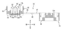
- FIG. 7 is a perspective view of the connector, the first cable and the second cable when the insulating housing is in a locked state.
- FIG. 9 is a cross-sectional view taken along the line IX-IX in FIG.
- FIG. 9 is a cross-sectional view taken along the line XX in FIG. 8
- FIG. 9 is a cross-sectional view taken along the line XI-XI in FIG. 8
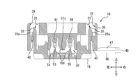
- It is the perspective view which showed a mode that the insulating housing in the unfolded state was filled with the filler.
- It is sectional drawing corresponding to FIG. 9 which showed the locked state of the connector which loaded the filler.
- It is an expanded sectional view corresponding to Drawing 13 which expanded an engaging part of the 1st lock part concerning the modification, and the 2nd lock part.
- the structure of the connector 10 in a state in which the filler 70 is not loaded will be mainly described.
- FIG. 1 is a perspective view of the connector 10, the first cable 60, and the second cable 65 according to an embodiment when the insulating housing 15 is in the unfolded state.
- FIG. 2 is a cross-sectional view taken along the line II-II in FIG.
- the connector 10 of one embodiment comprises an insulating housing 15 and relay contacts 50 (contacts) as large components.
- the insulating housing 15 is a molded product made of, for example, an insulating synthetic resin material.
- the insulating housing 15 has a first split housing 16 (fitting object) and a second split housing 30 (fitting object).
- the insulating housing 15 has a first connecting portion 46 and a second connecting portion 47 (connecting portion) as a connecting portion for connecting the first divided housing 16 and the second divided housing 30.
- the insulating housing 15 integrally has a first divided housing 16, a second divided housing 30, and a first connecting portion 46 and a second connecting portion 47.
- FIG. 3 is an enlarged perspective view of only the first divided housing 16 in a state in which the relay contact 50 is not provided.
- the structure of the first split housing 16 will be described in detail with reference to FIG.
- An outer peripheral edge portion of one surface (upper surface in FIG. 3) of the first divided housing 16 in the thickness direction is formed by the outer peripheral wall 17.
- An inner peripheral side of the outer peripheral wall 17 of the first divided housing 16 is constituted by an inner peripheral side recessed portion 17 a recessed one step downward from the upper surface of the first divided housing 16.
- the bottom surface of the inner peripheral side recess 17 a is formed by an inner peripheral first opposing surface 17 b which is a plane parallel to the upper surface of the first divided housing 16.
- a central portion located on the inner peripheral side of the inner peripheral first opposing surface 17b is constituted by a central first recess 17c which is recessed one step downward from the inner peripheral first opposing surface 17b.
- the bottom surface of the central first recess 17c is constituted by a central first opposing surface 17d formed of a plane parallel to the inner peripheral first opposing surface 17b.
- a contact attachment groove 18 is formed by the central first recess 17 c and the central first opposing surface 17 d.
- the contact mounting groove 18 has a fixing portion 18a, and an intermediate convex portion 18b located at the middle in the left-right direction of the fixing portion 18a, and narrowing the longitudinal width of the fixing portion 18a to divide the fixing portion 18a into left and right pairs.
- the middle convex portion 18b constitutes an upper portion, and includes a partition 18b1 (first partition) having a narrow width, and a protrusion 18b2 which is continuously formed immediately below the partition 18b1 and has a wide width.
- the middle convex portion 18 b is formed in a substantially convex shape in a front view from the front.
- projections 18c are formed, which narrow the front-rear width similarly to the intermediate projection 18b.
- a substantially cylindrical positioning protrusion 18d is provided in a protruding manner on the bottom surface (central first opposing surface 17d) of the pair of fixing portions 18a.
- the outer peripheral wall 17 of the first divided housing 16 is provided with a pair of first cable attachment grooves 19 which are located on the front and rear sides of one of the fixed portions 18a and which are located on the same straight line.
- a pair of second cable attachment grooves 20 located on the front and rear sides of the other fixed portion 18a and located on the same straight line are recessed.
- the second cable mounting groove 20 is parallel to the first cable mounting groove 19.
- the front shape of the first cable mounting groove 19 and the second cable mounting groove 20 is semicircular.
- the front and rear surfaces of the outer peripheral wall 17 of the first divided housing 16 are provided with a pair of inclined surfaces 19 a that are inclined outward from the deepest bottom surface of the pair of first cable attachment grooves 19 downward.
- the front and rear surfaces of the outer peripheral wall 17 of the first divided housing 16 are provided with a pair of inclined surfaces 20 a that are inclined outward from the deepest bottom surface of the pair of second cable attachment grooves 20 downward.
- flat lids 21 and 22 extending in the front-rear direction from the lower position than the front and rear inclined surfaces 19a and 20a are provided.
- the opposing surfaces 21a and 22a of the lids 21 and 22 are located at the same height as the lowermost portions of the inclined surfaces 19a and 20a.
- a pair of elastic first lock portions 25 is formed on the left and right sides of the outer peripheral wall 17 of the first divided housing 16.
- a pair of recessed portions 25 a is formed between each first lock portion 25 and the front and rear surfaces of the outer peripheral wall 17.
- Each first lock portion 25 has a first lock projection 26 projecting outward from the side surface of the first divided housing 16.
- the first locking projection 26 extends in the front-rear direction.
- Each first locking projection 26 has an inclined surface 26 a that inclines to the outside of the first divided housing 16 as it goes downward.
- the first lock portion 25 is formed at the upper edge portion of the inner surface, and has an inclined surface 26 b which inclines toward the inside of the first divided housing 16 as it goes downward.
- FIG. 4 is an enlarged perspective view of only the second divided housing 30.
- the structure of the second divided housing 30 will be described in detail with reference to FIG.
- An outer peripheral wall 31 protrudes from an outer peripheral edge portion of one surface (upper surface in FIG. 4) of the second divided housing 30 in the thickness direction.
- the portion located on the inner peripheral side of the outer peripheral wall 31 of the second divided housing 30 is constituted by an inner peripheral side recess 31 a which is recessed one step from the upper edge portion of the outer peripheral wall 31.
- the bottom surface of the inner peripheral side recess 31 a is constituted by an inner peripheral second opposing surface 31 b which is a plane parallel to the upper surface of the second divided housing 30.
- a cable pressing projection 32 having a pair of left and right U-shaped first pressing grooves 32a and second pressing grooves 32b is provided in a protruding manner on the inner peripheral second opposing surface 31b.
- the cable pressing protrusion 32 has a central protrusion 32 c and protrusions 32 d and 32 e on both sides in the left-right direction of the central protrusion 32 c.
- a first pressing groove 32a is formed between the central protrusion 32c and one of the protrusions 32d.
- a second pressing groove 32b is formed between the central protrusion 32c and the other protrusion 32e.
- the narrow partition 33 (2nd partition) extended along an up-down direction is formed in the front-back both sides of the center permite
- the second divided housing 30 is formed with cable support arms 35 and 36 projecting from the front and rear surfaces.
- First cable holding grooves 35a, 36a and second cable holding grooves 35b, 36b are provided on the upper surfaces of the cable support arms 35, 36.
- the front cable support arm 35 and the rear cable support arm 36 have a pair of projecting pieces 37a in which the front end portion and the rear end portion of the first cable holding grooves 35a and 36a are divided into left and right spaces by gaps. And a pair of projecting pieces 38a.
- the front end side and the rear end portion of the second cable holding grooves 35b and 36b are a pair of protrusions separated by gaps in the left and right It is formed of piece 37b and a pair of projecting pieces 38b, respectively.
- the pair of projecting pieces 37a, 38a, 37b, 38b, in particular, the left and right outer projecting pieces of the cable support arms 35, 36 are elastically bent in the left-right direction, and the distance between adjacent projecting pieces is variable.
- claws opposed to each other are protruded from the lower end of the front and rear end.
- the first cable holding grooves 35a and 36a and the second cable holding grooves 35b and 36b are grooves having a depth for inserting and holding the first cable 60 and the second cable 65 over the entire diameter (the entire diameter is accommodated). .
- the first cable holding grooves 35a, 36a have inclined surfaces 35e, 36e that are inclined upward as going outward.
- the first cable 60 is inserted and held in the first cable holding grooves 35a, 36a, the first cable 60 is along the inclined surfaces 35e, 36e of the first cable holding grooves 35a, 36a as shown in FIG. And the corresponding cable portion is inclined in the vertical direction.
- the second cable holding grooves 35b and 36b have inclined surfaces 35f and 36f, and the second cable 65 is also inserted and held in the second cable holding grooves 35b and 36b in the same manner as the first cable 60. Ru.
- a pair of dropout prevention protrusions 35c and a pair of dropout prevention protrusions 36c are provided on upper front end portions of the front and rear end portions of the first cable holding grooves 35a and 36a (facing surfaces of the projecting pieces 37a and 38a).
- a pair of dropout prevention protrusions 35d and a pair of dropout prevention protrusions 36d are provided on the upper openings of the front and rear ends of the second cable holding grooves 35b and 36b (oppositely facing surfaces of the projecting pieces 37b and 38b).
- the detachment preventing protrusions 35c, 36c and 35d, 36d allow the first cable 60 and the second cable 65 to be inserted into the first cable holding grooves 35a, 36a and the second cable holding grooves 35b, 36b, respectively.
- the pair of projecting pieces 37a and 38a and the pair of projecting pieces 37b and 38b are bent so as to widen the distance in the left-right direction (the distance between the pair of falling-off preventing protrusions 35c, 36c and 35d, 36d).
- the pair of detachment prevention protrusions 35c, 36c and 35d, 36d become the first cable 60.
- the second cable 65 respectively.
- the pair of projecting pieces 37a and 38a and the pair of projecting pieces 37b and 38b elastically bend in the direction in which the distance in the left-right direction is narrowed. Therefore, the pair of projecting pieces 37a and 38a and the pair of projecting pieces 37b and 38b are respectively inserted into the first cable holding grooves 35a and 36a and the second cable holding grooves 35b and 36b.
- the movement of the cable 65 in the cable extension direction is permitted while giving resistance.
- each of the pair of projecting pieces 37a, 38a and each pair of projecting pieces 37b, 38b are the first cable 60 and the second cable 65 from the first cable retaining grooves 35a, 36a and the second cable retaining grooves 35b, 36b, respectively. While giving a resistance to the force to be separated and acting as a retaining member so as not to be easily separated, it is possible to separate by a certain external force or more. The retaining action is maintained even if the second split housing 30 is turned upside down.
- a pair of second lock portions 39 is formed on the left and right sides of the outer peripheral wall 31 of the second divided housing 30.
- the pair of second lock portions 39 is formed on the inner surface of the second divided housing 30.
- Each second lock portion 39 has a second lock projection 40 projecting inward from the side surface of the second divided housing 30.
- a pair of convex walls 41 extending in the vertical direction is formed.
- Each second locking projection 40 has a substantially rectangular parallelepiped shape, and is formed on the inner surface of the second divided housing 30 so as to extend between the pair of convex walls 41. The second locking projection 40 extends in the front-rear direction.
- FIG. 5 is a perspective view showing the entire insulating housing 15 without the relay contact 50.
- the first divided housing 16 and the second divided housing 30 are linearly connected from the front and rear pair of first connection portions 46 linearly extending from the first divided housing 16 and the second divided housing 30. It connects by the pair of 2nd connection parts 47 which extend in the back and front, and the part 48 easy to bend.
- the bendable portion 48 connects the first connection portion 46 and the second connection portion 47.
- the pair of front and rear first connection portions 46 and the pair of front and rear second connection portions 47 are located on the same plane with each other in the unfolded state.
- the easily bendable portion 48 is thinner than the first and second connection portions 46 and 47.
- the first and second connection portions 46 and 47 are valley-folded (the first divided housing 16 and the second divided housing in FIG. 1, FIG. 5, etc.) with the bendable portions 48 extending in the front-rear direction as bending lines. 30 is bendable in the direction in which it approaches (easiness).
- the bending stiffness of the first connection portion 46 is set smaller than that of the second connection portion 47.
- the first divided housing 16, the first connecting portion 46, the bendable portion 48, the second connecting portion 47, and the second divided housing 30 autonomously maintain this expanded state in the expanded state shown in FIGS. It has a certain degree of strength (rigidity).
- FIG. 6 is a perspective view of the relay contact 50 alone. The structure of the relay contact 50 will be described in detail with reference to FIG.
- the relay contact 50 is formed by processing a thin plate of a spring-elastic copper alloy (for example, phosphor bronze, beryllium copper, titanium copper) or a corson based copper alloy into a shape shown in the figure by using a progressive die (stamping). After forming a base by nickel plating, tin copper plating or tin plating (or gold plating) is applied to the surface of the relay contact 50.
- a spring-elastic copper alloy for example, phosphor bronze, beryllium copper, titanium copper
- a corson based copper alloy for example, phosphor bronze, beryllium copper, titanium copper
- Relay contact 50 has a pair of flat base members 51 extending in the left-right direction and a pair of flat members extending in a direction orthogonal to base member 51 protruding at one end of front and rear side edges of base member 51.
- the longitudinal width of the pair of first cable displacement pieces 52 and the longitudinal width of the pair of second cable displacement pieces 54 are substantially the same.
- Circular positioning holes 51 a are formed on the left and right of the base piece 51.
- the first and second pressure welding grooves 53 and 55 are formed on the front and rear first and second cable pressure welding pieces 52 and 54, respectively.
- the first and second pressure welding grooves 53 and 55 are linearly extending toward the base piece 51. Be done.
- An upper end opening portion of the first pressure welding groove 53 is formed in a substantially V shape which is expanded upward by the tip end portion 52a.
- the upper end opening of the second pressure welding groove 55 is formed in a substantially V-shape which is expanded upward by the tip end portion 54a.
- the first cable pressure contact piece 52, the first pressure contact groove 53, and the tip 52a constitute a pressure contact portion P1.
- the second cable pressure-contacting piece 54, the second pressure-contacting groove 55, and the tip end portion 54a constitute a pressure-contacting portion P2.
- the relay contact 50 has a pair of pressure contact parts P1 and P2. As shown in FIG. 6, the pair of pressure contact parts P1 and P2 are separated from each other. The pair of pressure contact parts P1 and P2 are arranged in a straight line along a direction substantially perpendicular to the fitting direction, that is, in the left-right direction. A slit portion S is formed between the pair of pressure contact portions P1 and P2.
- the pair of pressure contact parts P1 and P2 have, for example, the same shape and size as each other.
- the pressure contact parts P1 and P2 have shapes substantially line-symmetrical with respect to straight lines L1 and L2 along the fitting direction, that is, the vertical direction.
- the pressure contact portion P1 is formed symmetrically about the first pressure contact groove 53 in the lateral direction.
- the pressure contact portion P2 is formed symmetrically about the second pressure contact groove 55 in the left-right direction.
- the relay contact 50 is formed continuously with a pair of front and rear pressure contact portions P1 and a pair of front and rear pressure contact portions P2, and has narrow portions 52b and 54b that are narrower than the respective pressure contact portions.
- the pair of first and second front and rear pressure-contacting pieces 52 and 54 are connected to the base piece 51 via the narrow portions 52b and 54b.
- the distance between the opposing edges of the first cable displacement piece 52 and the second cable displacement piece 54 positioned in the left-right direction, that is, the lateral width of the slit portion S, is narrower than the distance between the opposing edges of the narrow portions 52b and 54b. .
- the narrow portions 52b and 54b are each configured to have a shape that is substantially line-symmetrical to the pressure contact portions P1 and P2 with respect to the straight lines L1 and L2 along the fitting direction.
- the left side surface of the narrow portion 52b is continuously formed to be inward from the left side surface of the pressure contact portion P1.
- the right side surface of the narrow portion 52b is continuously formed in a manner symmetrical to the left side surface so as to be directed inwardly from the right side surface of the pressure contact portion P1.
- the left and right side surfaces of the narrow portion 54b are continuously formed so as to narrow inward in the leftward and rightward directions respectively from the left and right side surfaces of the pressure contact portion P2.
- the press-contact part P1 and the narrow part 52b are integrally formed as a line symmetrical shape centering on the straight line L1.
- the press-contact part P2 and the narrow part 54b are integrally formed as a line symmetrical shape centering on the straight line L2.
- the narrow parts 52b and 54b Similar to the pair of press-contact parts P1 and P2, the narrow parts 52b and 54b have, for example, the same shape and size.
- a play portion 51b is provided between the narrow portions 52b and 54b. Only the slit portion S is provided between the first cable pressure welding piece 52 and the second cable pressure welding piece 54, and no other member such as an insulator is interposed.
- the relay contact 50 is contained in a state in which the relay contact 50 is in electrical communication with the first cable 60 and the second cable 65 when the first split housing 16 and the second split housing 30 are fitted. More specifically, the relay contact 50 has the insulating cover 62 and the insulating cover 62 by the first pressure contact groove 53 and the second pressure contact groove 55 when the first divided housing 16 and the second divided housing 30 are fitted. The sheaths 67 are respectively cut to electrically connect the first cable 60 and the second cable 65 to each other. After fitting, the relay contact 50 sandwiches the core wire 61 and the core wire 66 with the first pressure contact groove 53 and the second pressure contact groove 55, respectively, to electrically connect the first cable 60 and the second cable 65 to each other.
- the first cable 60 and the second cable 65 have a tube-like and flexible and insulating surface of core wires 61 and 66 (a stranded wire or a single wire) made of a conductive and flexible material (for example, copper or aluminum). It is what was covered by the coating 62,67 which has sex, respectively.
- the first cable 60 is a cable that is wired from the beginning inside the wiring object (for example, a car or the like) and connected to the power supply of the wiring object.
- the second cable 65 is a cable that is additionally connected to the first cable 60 later.
- An electronic device or an electric device (for example, a car navigation system) or the like is connected to one end (front end) thereof.
- FIG. 7 is a perspective view of the connector 10, the first cable 60 and the second cable 65 at the stage when the insulating housing 15 transitions from the deployed state to the locked state.
- FIG. 8 is a perspective view of the connector 10, the first cable 60 and the second cable 65 when the insulating housing 15 is in the locked state.
- FIG. 9 is a cross-sectional view taken along the line IX-IX in FIG.
- FIG. 10 is a cross-sectional view taken along the line XX in FIG. 11 is a cross-sectional view taken along the line XI-XI in FIG.
- the relay contact 50 is fitted to the contact mounting groove 18 of the first divided housing 16 in the unfolded state shown in FIGS. 1 and 5 by hand or the like.
- the base piece 51 is fitted to the bottom of the contact attachment groove 18 while the play 51b is fitted to the intermediate projection 18b in a state where the left and right end portions of the base piece 51 are respectively fitted to the protrusions 18c. .
- a half (the lower half in FIG. 1 and FIG.
- the relay contact 50 is positioned relative to the first divided housing 16 Be done.
- the front and rear first pressure contact grooves 53 are positioned on an axis passing through the front and rear first cable attachment grooves 19, and pass through the front and rear second cable attachment grooves 20.
- the front and rear second pressure contact grooves 55 are positioned on the axis.
- the assembly worker presses the first cable 60 and the second cable 65 against the resistance of the front and rear drop prevention protrusions 35c, 36c and 35d, 36d with a hand or the like (see FIG. 1). At that time, each of the projecting pieces 37a, 38a, 37b, 38b is flexed against the elastic force to widen the interval between the opposing detachment preventing projections 35c, 36c and 35d, 36d.
- the first cable 60 and the second cable 65 are respectively pushed into the first cable holding grooves 35a, 36a and the second cable holding grooves 35b, 36b, the distance between the opposing detachment preventing protrusions 35c, 36c and 35d, 36d is narrowed.
- the first cable 60 and the second cable 65 are disposed between the bottoms of the first cable holding grooves 35a, 36a and the bottoms of the second cable holding grooves 35b, 36b and the detachment preventing protrusions 35c, 36c and 35d, 36d. Each one is held. Thereby, the first cable 60 and the second cable 65 can move in the cable extension direction while receiving resistance. Therefore, position adjustment of the extension direction of the 1st cable 60 and the 2nd cable 65 to connector 10 of a deployment state shown in Drawing 1 and Drawing 2 is possible.
- resistance is applied to prevent the separation.
- the first cable 60 and the second cable 65 do not easily come off from the first cable holding grooves 35a, 36a and the second cable holding grooves 35b, 36b, respectively.
- the first cable 60 and the second cable 65 can be separated from the first cable holding grooves 35a, 36a and the second cable holding grooves 35b, 36b, respectively, by a predetermined biasing force or more. Therefore, it is easy to replace the connector 10 and to change the first cable 60 and the second cable 65 to be attached to and detached from the connector 10.
- the first and second cable holding grooves 35a and 36a and the second cable holding grooves 35b and 36b are aligned with each other in the lateral direction, and the first and second cable holding grooves 35a and 36b are centered.
- the second divided housing 30 (the second connection portions 47 on the front and rear sides) is rotated so as to approach the first divided housing 16 (the first connection portions 46 on the front and rear sides).
- the second locking projection 40 on the first divided housing 16 side abuts on the inclined surface 26 a of the corresponding first locking projection 26.
- the corresponding first locking projections 26 elastically deform in the inward direction of the first divided housing 16 while sliding the corresponding second locking projections 40 downward on the corresponding inclined surfaces 26 a.
- the second pressing groove 32 b of the cable pressing projection 32 located on the second connection portion 47 side slightly pushes the middle portion of the second cable 65 into the back side (downward) of the second pressure welding groove 55. Thereby, the middle portion of the second cable 65 enters the space between the front and rear second cable displacement pieces 54.
- the second divided housing 30 is further rotated in the direction approaching the first divided housing 16 centering on the front and rear easy bending portions 48 by a hand or the like.
- the first pressing groove 32a of the cable pressing projection 32 located on the opposite side of the second connection portion 47 forms the middle portion of the first cable 60 with respect to the leading end portion 52a of the first cable pressing piece 52. Press in the direction of extension of or near this. Therefore, the first cable 60 is sandwiched by the tip 52 a and the cable pressing projection 32.
- the first divided housing 16 and the second divided housing are carried out by a general tool (for example, pliers) which is not shown.
- 30 is pressed substantially parallel to the direction in which they approach each other.
- Each second locking projection 40 engages with the corresponding first locking projection 26.
- Each convex wall 41 of the second lock portion 39 engages with the corresponding concave portion 25a.
- the cable pressing projection 32 further pushes the middle portion of the first cable 60 and the second cable 65 into the back side (bottom side) of the first pressure welding groove 53 and the second pressure welding groove 55, respectively. Therefore, the first cable 60 is pushed from the distal end portion 52 a to a substantially central portion of the first pressure welding groove 53. The second cable 65 is pushed from the leading end 54 a to a substantially central portion of the second pressure welding groove 55. At this time, the pressing directions of the first cable 60 and the second cable 65 by the first pressing groove 32a and the second pressing groove 32b of the cable pressing projection 32 are the vertical direction (the first pressing groove 53 and the second pressing groove Approximately parallel to the extension direction of 55).
- the left and right sides of the cover 62 of the first cable 60 are broken by the inner surfaces (right and left) of the first pressure contact groove 53.
- the left and right side portions of the cover 67 of the second cable 65 are broken by the inner surfaces (right and left) of the second pressure welding groove 55. Therefore, when the insulating housing 15 is held in the closed state, the inner surfaces (a pair of opposing surfaces) of the first pressure contact groove 53 contact (pressure contact) uniformly and reliably with both sides of the core wire 61.
- the inner surfaces (a pair of opposing surfaces) of the second pressure contact groove 55 contact (pressure contact) uniformly and reliably with both sides of the core wire 66.
- the core wire 61 of the first cable 60 and the core wire 66 of the second cable 65 are electrically conducted to each other through the relay contact 50 in the connector 10.
- part of the core wires 61 and 66 is a first pressure welding groove. It is not cut off by the groove 53 for the second and the second pressure contact 55. Therefore, since the mechanical strength of the core wires 61 and 66 does not decrease, there is little possibility that the core wires 61 and 66 may be completely cut even if a tensile force acts on the first cable 60 and the second cable 65. Therefore, it is possible to improve the contact reliability between the first cable 60 and the second cable 65 and the relay contact 50.
- the facing surfaces 21 a and 22 a of the lids 21 and 22 of the first split housing 16 are A part of the opening (upper opening in FIG. 4) of the first cable holding grooves 35a, 36a and the second cable holding grooves 35b, 36b is closed.
- the first cable 60 is vertically sandwiched by the pair of inclined surfaces 19 a of the first divided housing 16 and the inclined surfaces 35 e and 36 e of the corresponding second divided housing 30.
- the second cable 65 is vertically sandwiched by the pair of inclined surfaces 20 a of the first divided housing 16 and the inclined surfaces 35 f and 36 f of the corresponding second divided housing 30.
- relay contacts are formed on the surfaces 62, 67 of the first cable 60 and the second cable 65. Close contact without disturbing the electrical continuity with 50. Therefore, even if the first cable 60 or the second cable 65 is shaken and bent by an external force applied on the outside of the connector 10, the movement and stress caused by the bending of the first cable 60 or the second cable 65 are relay contacts It is possible to suppress transmission to the contact portion with 50 and maintain contact reliability.
- the partition wall 33 of the second divided housing 30 is fitted in the slit portion S of the relay contact 50.
- the partition wall 18b1 of the first divided housing 16 is fitted into the slit portion S of the relay contact 50.
- the partition wall 18 b 1 and the partition wall 33 fit into the slit portion S in a state where they face each other in the vertical direction in the locked state.
- the pair of pressure contact parts P1 and P2 separated from each other by the slit part S are separated by the partition 18b1 and the partition 33 in a state where the predetermined gap is formed with the partition 18b1 and the partition 33.
- the projection 18b2 of the first divided housing 16 is fitted between the pair of narrow portions 52b and 54b which are wider than the slit portion S.
- the protrusions 18c of the first divided housing 16 are located outward of each other so as to be adjacent to the pair of narrow portions 52b, 54b.
- the filler 70 is provided to the first divided housing 16 and the second divided housing 30, respectively (a first filler 70a and a second filler 70b).
- the first filler 70a and the second filler 70b may be bonded and integrated with each other when the first divided housing 16 and the second divided housing 30 are fitted, or they may be adhered to each other to form a joint surface. You may form.
- the filler 70 may be any material having cohesion or tackiness, such as a waterproof gel, a UV curable resin, or an adhesive.
- FIG. 12 is a perspective view showing the insulating housing 15 loaded with the filler 70 in the unfolded state.
- FIG. 13 is a cross-sectional view corresponding to FIG. 9 showing the locked state of the connector 10 loaded with the filler 70.
- the filler 70 is interposed between the inner peripheral first opposing surface 17 b of the first split housing 16 and the inner peripheral second opposing surface 31 b of the second split housing 30.
- the first filler 70a intervened in the inner peripheral first opposing surface 17b of the first divided housing 16 has a lower surface substantially the same as the inner peripheral first opposing surface 17b in plan view, and the periphery of the relay contact 50 It is formed to surround the
- the height of the first filler 70a is a height at which the first filler 70a and the second filler 70b bond or stick when the first divided housing 16 and the second divided housing 30 are fitted. is there.
- the second filler 70b intervened in the inner peripheral second opposing surface 31b of the second divided housing 30 has a lower surface substantially the same as the inner peripheral second opposing surface 31b in plan view, and the periphery of the cable pressing projection 32 It is formed to surround the
- the height of the second filler 70b is a height at which the first filler 70a and the second filler 70b bond or stick when the first divided housing 16 and the second divided housing 30 are fitted. is there.
- the entire inside of the fitted first divided housing 16 and second divided housing 30 is filled with the filler 70, as shown in FIG. More specifically, when the first divided housing 16 and the second divided housing 30 are in the locked state, the filler 70 is applied to the first inner facing surface 17b and the second inner facing surface 31b. Close contact and surround the relay contact 50.
- the first filler 70a and the second filler 70b crush each other to be in a compressed state once, and firmly adhere.
- the filler 70 is made of a material having cohesion
- the first filler 70 a and the second filler 70 b are integrated by a chemical reaction such as a hydrogen bond.
- the filler 70 is made of a tacky material
- the first filler 70a and the second filler 70b form a bonding surface and stick to each other.
- the filler 70 seals the periphery of the relay contact 50.
- the first cable 60 and the second cable 65 extend outward from the relay contact 50 disposed inside the filler 70 in a locked state.
- the first cable 60 and the second cable 65 extend outward in the front-rear direction from the pressure contact portion of the relay contact 50.
- the filler 70 abuts on the inner surfaces of the pair of first lock portions 25 of the first divided housing 16. As shown in FIG. 13, the engagement surfaces 27 of the first locking projections 26 and the second locking projections 40 are located within the width of the filler 70 along the vertical direction in the vertical direction. When the first divided housing 16 and the second divided housing 30 are fitted, the surface of the second locking projection 40 abuts on the outer surface of the first locking portion 25. The contact surface 42 formed thereby is substantially parallel to the inner surface of the first lock 25 that contacts the filler 70.
- the connector 10 can effectively suppress the entry of external foreign matter such as water or dust.
- the connector 10 improves the accuracy of the pressure contact of the first cable 60 and the second cable 65 in the relay contact 50 to improve the contact reliability between each cable and the relay contact 50. it can. As described below, the connector 10 can improve the contact reliability between each cable and the relay contact 50 by optimizing the opening associated with the pressure contact of the pressure contact portions P1 and P2.
- the connector 10 can accurately press each of the first cable 60 and the second cable 65 by the pair of press-contact parts P1 and P2 being separated from each other in the relay contact 50. With the pair of pressure contact parts P1 and P2 being separated from each other, the connector 10 can secure a space in which the first cable pressure contact piece 52 is deformed outward along the left and right directions. Similarly, the connector 10 can secure a space in which the second cable displacement piece 54 is deformed outward along the left and right directions. Thus, when each cable is pushed into the corresponding pressure contact groove, the corresponding cable pressure contact piece can be deformed outward along the left and right directions. Therefore, the connector 10 can press the first cable 60 and the second cable 65 accurately while suppressing a defect such as core wire spillage.
- the connector 10 can prevent the excessive opening of the pair of pressure contact parts P1 and P2 accompanying the pressure contact of the first cable 60 and the second cable 65 by having the partition wall 18b1 and the partition wall 33.
- the pressure contact portions P1 and P2 are excessively opened along the left-right direction as the pressure contact of the cables is caused, the end of the pressure contact portions P1 and P2 contacts the partition wall 18b1 or the partition wall 33.
- the further opening of the pressure contact parts P1 and P2 is restricted. Therefore, the connector 10 can accurately press the first cable 60 and the second cable 65 while suppressing a defect such as winding of the coating of each cable.
- the connector 10 has the partition wall 18b1 and the partition wall 33, so that the relay contact 50 can be accurately positioned before and after fitting together with the positioning projection 18d. Thereby, when the first cable 60 and the second cable 65 are brought into pressure contact with the relay contact 50, even when an external force is applied to the pressure contact parts P1, P2 unintentionally, the pressure contact parts P1, P2 are obtained by the partition 18b1 and the partition 33. Can be suppressed from being deformed.
- the connector 10 can form the relay contact 50 in a symmetrical shape by providing the slit portion S and arranging the pair of pressure contact portions P1 and P2 in the left-right direction. Thereby, the connector 10 can make the relay contact 50 compact in a state in which the deformation allowance space of each of the first cable pressure welding piece 52 and the second cable pressure welding piece 54 is secured.
- the connector 10 can further improve the accuracy regarding the pressure contact of the first cable 60 and the second cable 65 by arranging the pair of pressure contact parts P1 and P2 in the left-right direction.
- the pressure contact portion P1 is formed symmetrically with respect to the first pressure contact groove 53 so that the first cable pressure contact piece 52 when the first cable 60 is pushed into the first pressure contact groove 53.
- the deformation in both the left and right directions can be made uniform.
- the press-contact parts P2 are formed symmetrically in the left-right direction, the deformation of the second cable press-contacting piece 54 in the left and right directions can be made uniform.
- the relay contact 50 can exert forces to the left and right uniformly on the first cable 60 and the second cable 65 during pressure welding.
- the connector 10 can prevent part of the core wires 61 and 66 from leaking to the outside without being accommodated in the first pressure welding groove 53 and the second pressure welding groove 55, respectively, and defects such as core wire spillage can be suppressed.
- the connector 10 can prevent only one of the left and right sides of the coating of each cable from being cut off and the other from being wound up, and can suppress a defect such as winding of the coating of each cable.
- the connector 10 can miniaturize the relay contact 50 by having the narrow portions 52 b and 54 b.
- the connector 10 can reduce the width in the left-right direction of the relay contact 50, and can contribute to the reduction in size and weight as a whole.
- the connector 10 separates the first cable displacement piece 52 and the second cable displacement piece 54 by the narrow slit portion S, and does not interpose another member such as an insulator in the slit portion S. It can contribute to reduction in size and weight.
- the connector 10 can elastically deform the press contact parts P1 and P2 more largely by having the narrow parts 52b and 54b.
- the crimped portions P1 and P2 can be elastically deformed more largely along the left-right direction by being narrowed at the roots in the connection portions with the narrow portions 52b and 54b.
- the connector 10 can further improve the accuracy of the pressure contact of the first cable 60 and the second cable 65 by suppressing a defect such as core wire spillage.
- the connector 10 can facilitate the forming process of the relay contact 50 and contribute to the improvement of productivity.
- the connector 10 integrally forms the press-contacting portion P1 and the narrow-width portion 52b in a symmetrical manner, so that the force applied to the press-contacting portion P1 and the narrow-width portion 52b when the first cable 60 is pushed is It can be uniform.
- the connector 10 can make the force applied to the pressure contact portion P2 and the narrow portion 54b uniform on the left and right sides when the second cable 65 is pushed. Thereby, the connector 10 can suppress defects such as core wire spillage and winding of the coating of each cable, and can further improve the accuracy of pressure welding.
- the first and second cables 60 and 65 having the same specifications can be obtained by having the same shapes and sizes as the pressure-welding portion P1, the narrow width portion 52b, and the pressure-contact portion P2 and the narrow width portion 54b.
- the same pressure contact performance can be realized.
- the partition wall 18b1 and the partition wall 33 face each other along the vertical direction at the time of fitting, thereby preventing excessive opening of the pressure contact portions P1 and P2 in a state in which the width in the horizontal direction of the slit portion S is narrowed. it can. Since the partition wall 18b1 and the partition wall 33 are adjacent to substantially the entire pressure-welding portions P1 and P2 along the vertical direction, the connector 10 can prevent the pressure-welding portions P1 and P2 from contacting each other in the left-right direction.
- the connector 10 includes the projection 18 b 2 so that the relay contact 50 can be accurately positioned before and after the fitting together with the positioning projection 18 d.
- the connector 10 positions the relay contact 50 with high accuracy relative to the first divided housing 16 by fitting the play 51b to the projection 18b2 and fitting the pair of positioning holes 51a to the pair of positioning projections 18d. it can.
- the connector 10 can perform the positioning of the relay contact 50 with higher accuracy by having the protrusion 18 c.
- the connector 10 can safely connect the first cable 60 and the second cable 65 together by being contained in the state in which the relay contact 50 is conducted with the cable.
- the connector 10 can improve the reliability as a product.
- the connector 10 can improve the contact reliability by bringing the core wires 61 and 66 of the first cable 60 and the second cable 65 into sandwiching by the first pressure contact groove 53 and the second pressure contact groove 55 respectively. it can. Thus, the connector 10 can ensure the electrical connection between the first cable 60 and the second cable 65.
- the filler 70 comes into contact with the inner surface of the first lock portion 25 so that the elastic first lock portion 25 is elastically deformed outward by the elastic force from the inside to the outside due to the expansion or swelling of the filler 70.
- the connector 10 since the lock portion is formed inside, the connector 10 can further strengthen the engagement between the first lock portion 25 and the second lock portion 39 by the elastic deformation to the outside. More specifically, since the engagement surface 27 of the first locking projection 26 and the second locking projection 40 is within the width of the inner surface of the first locking portion 25 in contact with the filler 70 in the vertical direction, The expansion force of the agent 70 is efficiently converted to the engagement force.
- the expansion force of the filler 70 is formed on the surfaces of the first lock portion 25 and the second lock projection 40. It travels in a direction substantially perpendicular to the other. Thereby, the expansion force of the filler 70 and the like are more efficiently converted into the engagement force.
- the connector 10 can further enhance the close contact state of the first divided housing 16 and the second divided housing 30.
- the connector 10 can suppress the opening action of the first divided housing 16 and the second divided housing 30 even in the state where the elastic force from the inside to the outside is applied.
- the connector 10 can maintain waterproofness. The effect appears also at normal temperature, but appears more remarkably as the expansion of the filler 70 increases at high temperature.
- the connector 10 can further suppress the opening between the first split housing 16 and the second split housing 30.
- the fillers 70 are disposed on the inner surfaces of the first split housing 16 and the second split housing 30 so that the respective fillers 70 stick in a locked state.
- the adhesive force is a resistance to the opening of the fitted first divided housing 16 and the second divided housing 30.
- the locking mechanism is formed inside the first divided housing 16 and the second divided housing 30 which are fitted, so that the outer wall can be formed in a substantially planar shape with less unevenness and through holes.
- the connector 10 can further improve the waterproofness, and can further suppress the entry of external foreign matter such as water or dust.
- a first locking projection 26 extending in one direction and a second locking projection 40 extending in the same direction are engaged to form a flat surface in which the engagement surface 27 extends in the same direction.
- the area of the engagement surface 27 can be increased, and the engagement can be made stronger.
- the connector 10 makes it easy to transmit the engaging force between the first locking projection 26 and the second locking projection 40 by the engagement surface 27 being substantially horizontal as shown in FIG. 13.
- FIG. 14 is an enlarged cross-sectional view corresponding to FIG. 13 in which the engaging portion between the first lock 25 and the second lock 39 according to the modification is enlarged.
- the engagement surfaces 27 of the first locking projection 26 and the second locking projection 40 are substantially horizontal planes extending in the front-rear direction, but the present invention is not limited thereto.
- the engagement surface 27 may be inclined downward from the inside to the outside of the fitted first divided housing 16 and the second divided housing 30.
- the connector 10 can further reduce the possibility of unlocking due to the cross-sectional shape.
- first lock portion 25 is formed in the first divided housing 16 and the second lock portion 39 is formed in the second divided housing 30, the present invention is not limited thereto.
- the first lock portion 25 having elasticity may be formed on the second divided housing 30 side not provided with the relay contact 50, and the second lock portion 39 may be formed on the first divided housing 16 side provided with the relay contact 50.
- the formation positions of the first lock portion 25 and the second lock portion 39 in the first divided housing 16 and the second divided housing 30 are not limited to the above, and the first divided housing 16 and the second divided housing 30 may be fitted together. It may be any forming position as long as it is possible to hold the lock.
- the first lock portion 25 and the second lock portion 39 are provided with the first lock projection 26 and the second lock projection 40 respectively, and are lock means with which the first lock projection 26 and the second lock projection 40 are engaged. But is not limited to this.
- the first lock 25 and the second lock 39 may have any locking means.
- the pair of pressure contact parts P1 and P2 are described as being arranged in a straight line with the slit part S interposed therebetween, the present invention is not limited to this.
- the pair of pressure contact parts P1 and P2 may be mutually offset in the front-rear direction as long as the accuracy of pressure contact can be ensured.
- the front-rear width of the pair of first cable displacement pieces 52 and the front-rear width of the pair of second cable displacement pieces 54 are described as being substantially the same, the present invention is not limited thereto.
- the respective front and rear widths may be different as long as the accuracy of pressure welding can be ensured.
- Each pressure contact portion has been described as having a laterally symmetrical shape, but is not limited thereto.
- Each pressure contact portion may have an asymmetrical shape as long as the accuracy of pressure contact can be maintained by suppressing defects such as core wire spillage.
- each narrow portion is described as being configured to have a shape that is narrowed symmetrically to the corresponding pressure contact portion, the present invention is not limited to this.
- Each narrow portion may be configured to have a shape that is narrowed asymmetrically in the left-right direction as long as defects such as core wire spillage can be suppressed.
- Each pressure contact portion and the corresponding narrow portion may be integrally formed asymmetrically in the left-right direction.
- the present invention is not limited thereto.
- the pair of press-contact portions and the narrow-width portions are formed in different modes so as to realize desired press-contact performance with respect to each cable according to the first cable 60 and the second cable 65 of different specifications. Good.
- partition 18 b 1 and the partition 33 are described as facing each other along the vertical direction at the time of fitting, it is not limited to this.
- the partition wall 18b1 and the partition wall 33 may be slightly offset from each other in the left-right direction.
- the connector 10 is described as having the protrusion 18 b 2, the present invention is not limited to this.
- the connector 10 may not have the projection 18 b 2 as long as the relay contact 50 can be accurately positioned by, for example, only the pair of positioning holes 51 a and the pair of positioning projections 18 d.
- relay contact 50 is described as being attached to the first divided housing 16, the present invention is not limited thereto.
- the relay contact 50 may be attached to the second split housing 30 or may be attached to both the first split housing 16 and the second split housing 30.
- the first and second split housings 16 and 30 are described as being filled with the first filler 70a and the second filler 70b, respectively, but the present invention is not limited thereto.
- the connector 10 may be configured such that only one of the first split housing 16 and the second split housing 30 has the filler 70, as long as appropriate waterproofness can be obtained.
- Three or more cables arranged in a direction substantially orthogonal to the extension direction of the portion of the cable supported by the connector 10 may be connected by the connector 10.
- three or more pairs of pressure contact grooves (aligned in the left-right direction) may be formed in one relay contact 50.
- a pressing groove may be formed in each of the plurality of relay contacts 50, two or more pairs of pressing grooves may be formed in at least one relay contact 50, and a cable (core wire) may be pressed by each pressing groove.
Landscapes
- Connections By Means Of Piercing Elements, Nuts, Or Screws (AREA)
- Details Of Connecting Devices For Male And Female Coupling (AREA)
- Connector Housings Or Holding Contact Members (AREA)
- Connections Effected By Soldering, Adhesion, Or Permanent Deformation (AREA)
Abstract
L'invention concerne un connecteur qui permet d'améliorer la fiabilité de contact entre un câble et un contact en augmentant la précision de contact avec la pression du câble dans le contact. Un connecteur (10) qui maintient un fil d'âme d'un câble au moyen de parties de contact par pression est pourvu : d'une paire d'objets d'ajustement à monter l'un sur l'autre ; d'un contact (50) qui comporte une paire de parties de contact par pression et qui est disposé à l'intérieur des objets d'ajustement ; d'une première paroi de séparation (18b1) qui est formée à l'intérieur de l'un des objets d'ajustement ; et d'une seconde paroi de séparation (33) qui est formée à l'intérieur de l'autre objet d'ajustement, les parties de contact par pression du contact (50) étant séparées l'une de l'autre, et séparées l'une de l'autre à l'intérieur des objets d'ajustement, étant ajustées l'une à l'autre, par la première paroi de séparation (18b1) et la seconde paroi de séparation (33).
Priority Applications (4)
| Application Number | Priority Date | Filing Date | Title |
|---|---|---|---|
| US16/629,938 US11018442B2 (en) | 2017-07-18 | 2018-07-05 | Connector having press contact portions separated by partition walls |
| KR1020207000545A KR102384162B1 (ko) | 2017-07-18 | 2018-07-05 | 커넥터 |
| CN201880045831.7A CN110870140B (zh) | 2017-07-18 | 2018-07-05 | 连接器 |
| EP18835848.5A EP3657603B1 (fr) | 2017-07-18 | 2018-07-05 | Connecteur |
Applications Claiming Priority (2)
| Application Number | Priority Date | Filing Date | Title |
|---|---|---|---|
| JP2017-139270 | 2017-07-18 | ||
| JP2017139270A JP6486419B2 (ja) | 2017-07-18 | 2017-07-18 | コネクタ |
Publications (1)
| Publication Number | Publication Date |
|---|---|
| WO2019017209A1 true WO2019017209A1 (fr) | 2019-01-24 |
Family
ID=65015738
Family Applications (1)
| Application Number | Title | Priority Date | Filing Date |
|---|---|---|---|
| PCT/JP2018/025495 Ceased WO2019017209A1 (fr) | 2017-07-18 | 2018-07-05 | Connecteur |
Country Status (6)
| Country | Link |
|---|---|
| US (1) | US11018442B2 (fr) |
| EP (1) | EP3657603B1 (fr) |
| JP (1) | JP6486419B2 (fr) |
| KR (1) | KR102384162B1 (fr) |
| CN (1) | CN110870140B (fr) |
| WO (1) | WO2019017209A1 (fr) |
Cited By (1)
| Publication number | Priority date | Publication date | Assignee | Title |
|---|---|---|---|---|
| CN114678710A (zh) * | 2020-12-24 | 2022-06-28 | 泰科电子(上海)有限公司 | 夹持端子 |
Families Citing this family (5)
| Publication number | Priority date | Publication date | Assignee | Title |
|---|---|---|---|---|
| US9885196B2 (en) | 2015-01-26 | 2018-02-06 | Hayward Industries, Inc. | Pool cleaner power coupling |
| KR102278635B1 (ko) * | 2020-07-16 | 2021-07-15 | 이은길 | 단자함 구조체 |
| CN116250152A (zh) | 2020-09-24 | 2023-06-09 | 京瓷Avx元器件公司 | 无焊接线对板单对以太网连接系统 |
| CN117981175A (zh) * | 2021-09-23 | 2024-05-03 | 京瓷Avx元器件公司 | 线对线汇接连接器 |
| CN119547277A (zh) * | 2022-08-29 | 2025-02-28 | 京瓷Avx元器件公司 | 具有线保持特征的绝缘刺穿接触件 |
Citations (5)
| Publication number | Priority date | Publication date | Assignee | Title |
|---|---|---|---|---|
| JPH04303569A (ja) * | 1991-03-29 | 1992-10-27 | Mikihiko Fuse | モニター可能なコネクター |
| JPH1092478A (ja) * | 1996-09-13 | 1998-04-10 | Yazaki Corp | 圧接コネクタ |
| JP3028988B2 (ja) | 1992-02-05 | 2000-04-04 | トヨタ自動車株式会社 | コネクタ |
| JP2011146310A (ja) * | 2010-01-16 | 2011-07-28 | Yasumitsu Matsuda | ネジ締め構造の導線圧入コネクター |
| WO2017046982A1 (fr) * | 2015-09-14 | 2017-03-23 | 京セラコネクタプロダクツ株式会社 | Connecteur de dérivation |
Family Cites Families (25)
| Publication number | Priority date | Publication date | Assignee | Title |
|---|---|---|---|---|
| US3899236A (en) * | 1974-06-24 | 1975-08-12 | Amerace Corp | Electrical connector |
| US3936128A (en) * | 1975-01-31 | 1976-02-03 | Bell Telephone Laboratories, Incorporated | Solderless electrical connector for connecting a plurality of insulated wires |
| US4444447A (en) * | 1982-05-24 | 1984-04-24 | Minnesota Mining And Manufacturing Company | Electrical wire connector |
| US4496206A (en) * | 1982-05-24 | 1985-01-29 | Minnesota Mining And Manufacturing Company | Side entry electrical wire connector |
| JPH0635379Y2 (ja) * | 1988-02-10 | 1994-09-14 | ミネソタ マイニング アンド マニユフアクチユアリング カンパニー | 高密度コネクタ |
| US5498172A (en) * | 1993-07-30 | 1996-03-12 | Sunx Kabushiki Kaisha | Electrical connector for interconnecting parallel multiconductor cables |
| JP2836463B2 (ja) * | 1993-10-26 | 1998-12-14 | 住友電装株式会社 | 圧接ジョイントコネクタ |
| JPH08162177A (ja) * | 1994-12-05 | 1996-06-21 | Yazaki Corp | 圧接コネクタへの電線圧接方法及び圧接コネクタ |
| JPH08306428A (ja) * | 1995-04-28 | 1996-11-22 | Fuji Hoon Seisakusho:Kk | 電線接続部品 |
| JPH0927355A (ja) * | 1995-07-10 | 1997-01-28 | Sumitomo Wiring Syst Ltd | 圧接コネクタ |
| JP3028988U (ja) | 1996-03-13 | 1996-09-17 | ヤーマン株式会社 | 光脱毛装置 |
| ZA976987B (en) * | 1996-08-16 | 1999-12-13 | Molex Inc | Electrical tap-off connector. |
| US6312282B1 (en) * | 1999-03-22 | 2001-11-06 | Ideal Industries, Inc. | Insulation displacement connector |
| US6890210B2 (en) * | 2003-03-21 | 2005-05-10 | Hon Hai Precision Ind. Co., Ltd. | Cable connector assembly with IDC contacts |
| ITPD20070020U1 (it) * | 2007-02-02 | 2008-08-03 | Inarca Spa | Connettore elettrico perfezionato |
| US7686661B2 (en) * | 2008-07-31 | 2010-03-30 | Tyco Electronics Corporation | Connection enclosure assemblies, connector systems and methods for forming an enclosed connection between conductors |
| JP2010153081A (ja) | 2008-12-24 | 2010-07-08 | Yazaki Corp | 照明ユニット |
| US8827738B2 (en) | 2009-11-03 | 2014-09-09 | Orica Explosives Technology Pty Ltd | Connector, and methods of use |
| DE102010051069A1 (de) * | 2010-11-12 | 2012-05-16 | Illinois Tool Works Inc. | Verbindungsvorrichtung und Verfahren zur Herstellung einer elektrisch leitenden Verbindung |
| FR2977384B1 (fr) * | 2011-06-28 | 2013-08-02 | App Mat Elect Const | Connecteur pour relier l'un a l'autre deux cables electriques |
| CN102723624B (zh) * | 2012-03-30 | 2014-04-16 | 深圳市拓普联科电子有限公司 | 市电电线连接组件及连接方法 |
| JP2016134231A (ja) * | 2015-01-16 | 2016-07-25 | 京セラコネクタプロダクツ株式会社 | 分岐コネクタ |
| JP6634235B2 (ja) | 2015-08-03 | 2020-01-22 | 日本航空電子工業株式会社 | 端子 |
| JP6397965B1 (ja) * | 2017-06-19 | 2018-09-26 | 京セラ株式会社 | コネクタ |
| US10541478B1 (en) * | 2017-10-04 | 2020-01-21 | The Patent Store, Llc | Insulation displacement connector |
-
2017
- 2017-07-18 JP JP2017139270A patent/JP6486419B2/ja active Active
-
2018
- 2018-07-05 WO PCT/JP2018/025495 patent/WO2019017209A1/fr not_active Ceased
- 2018-07-05 KR KR1020207000545A patent/KR102384162B1/ko active Active
- 2018-07-05 EP EP18835848.5A patent/EP3657603B1/fr active Active
- 2018-07-05 US US16/629,938 patent/US11018442B2/en active Active
- 2018-07-05 CN CN201880045831.7A patent/CN110870140B/zh active Active
Patent Citations (5)
| Publication number | Priority date | Publication date | Assignee | Title |
|---|---|---|---|---|
| JPH04303569A (ja) * | 1991-03-29 | 1992-10-27 | Mikihiko Fuse | モニター可能なコネクター |
| JP3028988B2 (ja) | 1992-02-05 | 2000-04-04 | トヨタ自動車株式会社 | コネクタ |
| JPH1092478A (ja) * | 1996-09-13 | 1998-04-10 | Yazaki Corp | 圧接コネクタ |
| JP2011146310A (ja) * | 2010-01-16 | 2011-07-28 | Yasumitsu Matsuda | ネジ締め構造の導線圧入コネクター |
| WO2017046982A1 (fr) * | 2015-09-14 | 2017-03-23 | 京セラコネクタプロダクツ株式会社 | Connecteur de dérivation |
Non-Patent Citations (1)
| Title |
|---|
| See also references of EP3657603A4 |
Cited By (1)
| Publication number | Priority date | Publication date | Assignee | Title |
|---|---|---|---|---|
| CN114678710A (zh) * | 2020-12-24 | 2022-06-28 | 泰科电子(上海)有限公司 | 夹持端子 |
Also Published As
| Publication number | Publication date |
|---|---|
| EP3657603A4 (fr) | 2021-01-27 |
| JP6486419B2 (ja) | 2019-03-20 |
| EP3657603B1 (fr) | 2024-10-30 |
| JP2019021511A (ja) | 2019-02-07 |
| US20200144735A1 (en) | 2020-05-07 |
| CN110870140B (zh) | 2022-03-18 |
| EP3657603A1 (fr) | 2020-05-27 |
| KR20200011547A (ko) | 2020-02-03 |
| KR102384162B1 (ko) | 2022-04-08 |
| US11018442B2 (en) | 2021-05-25 |
| CN110870140A (zh) | 2020-03-06 |
Similar Documents
| Publication | Publication Date | Title |
|---|---|---|
| WO2019017209A1 (fr) | Connecteur | |
| JP6397965B1 (ja) | コネクタ | |
| JP6397864B2 (ja) | 分岐コネクタ | |
| JP6550467B2 (ja) | 分岐コネクタ | |
| JP6466984B2 (ja) | コネクタ | |
| JP6401869B1 (ja) | コネクタ | |
| JP6598810B2 (ja) | コネクタ | |
| JP6466983B2 (ja) | コネクタ | |
| CN110663138B (zh) | 连接器和包装体 | |
| JP6401770B2 (ja) | 分岐コネクタ | |
| WO2018173685A1 (fr) | Connecteur | |
| JP2018160457A (ja) | コネクタ |
Legal Events
| Date | Code | Title | Description |
|---|---|---|---|
| 121 | Ep: the epo has been informed by wipo that ep was designated in this application |
Ref document number: 18835848 Country of ref document: EP Kind code of ref document: A1 |
|
| ENP | Entry into the national phase |
Ref document number: 20207000545 Country of ref document: KR Kind code of ref document: A |
|
| NENP | Non-entry into the national phase |
Ref country code: DE |
|
| ENP | Entry into the national phase |
Ref document number: 2018835848 Country of ref document: EP Effective date: 20200218 |