WO2019017472A1 - Dispositif d'affichage d'informations de guidage, grue et procédé de génération d'informations de guidage - Google Patents
Dispositif d'affichage d'informations de guidage, grue et procédé de génération d'informations de guidage Download PDFInfo
- Publication number
- WO2019017472A1 WO2019017472A1 PCT/JP2018/027280 JP2018027280W WO2019017472A1 WO 2019017472 A1 WO2019017472 A1 WO 2019017472A1 JP 2018027280 W JP2018027280 W JP 2018027280W WO 2019017472 A1 WO2019017472 A1 WO 2019017472A1
- Authority
- WO
- WIPO (PCT)
- Prior art keywords
- data
- guide information
- camera
- data processing
- processing unit
- Prior art date
- Legal status (The legal status is an assumption and is not a legal conclusion. Google has not performed a legal analysis and makes no representation as to the accuracy of the status listed.)
- Ceased
Links
Images











Classifications
-
- B—PERFORMING OPERATIONS; TRANSPORTING
- B66—HOISTING; LIFTING; HAULING
- B66C—CRANES; LOAD-ENGAGING ELEMENTS OR DEVICES FOR CRANES, CAPSTANS, WINCHES, OR TACKLES
- B66C13/00—Other constructional features or details
- B66C13/18—Control systems or devices
- B66C13/46—Position indicators for suspended loads or for crane elements
-
- B—PERFORMING OPERATIONS; TRANSPORTING
- B66—HOISTING; LIFTING; HAULING
- B66C—CRANES; LOAD-ENGAGING ELEMENTS OR DEVICES FOR CRANES, CAPSTANS, WINCHES, OR TACKLES
- B66C23/00—Cranes comprising essentially a beam, boom, or triangular structure acting as a cantilever and mounted for translatory of swinging movements in vertical or horizontal planes or a combination of such movements, e.g. jib-cranes, derricks, tower cranes
- B66C23/88—Safety gear
Definitions
- the present invention relates to a guide information display device for assisting a crane operation by an operator, a crane including the same, and a technique of generating guide information.
- Patent Document 1 an imaging unit attached near the tip of a boom, a display unit for displaying an image captured by the imaging unit, a crane controller for controlling the attitude of a mobile crane, and other mobile cranes are mutually used.
- a mobile crane including a communication unit for transmitting and receiving information to the imager, and an image controller for displaying information of other mobile cranes received from other mobile cranes superimposed on an image of the display unit
- An apparatus is disclosed.
- the image controller is configured to display, as information of another mobile crane, a movement limit line of a load of another mobile crane superimposed on the image of the display unit.
- the image controller calculates the maximum working radius centered on the turning center of the boom based on the load load and the outrigger overhang amount acquired by the crane controller.
- the image controller obtains coordinates of a range being imaged with the turning center as the origin based on the zoom magnification of the imaging unit (movie camera), the tilt angle, the pan angle, and the height position.
- the height of the imaging unit is calculated based on the boom length and the elevation angle acquired by the crane controller.
- the image controller converts the movement limit line, which is a curve indicating the area of the maximum work radius, into the absolute coordinate system to which the image captured by the imaging unit belongs, and superimposes the image on the image.
- the height of the imaging unit is determined by the crane length and the elevation angle acquired as crane information.
- the ground surface around the suspended load is
- the present invention has been made in view of such current problems, and has a guide information display device capable of displaying guide information that accurately represents the flow line of a suspended load, and a crane including the guide information display device It is an object of the present invention to provide a method of generating guide information capable of generating guide information that accurately represents the flow line of a suspended load.
- the guide information display device includes at least the suspended load and the ground surface from above the suspended load suspended by the wire suspended from the boom and moved according to the operation of the boom.
- a data acquisition unit including a camera for capturing an image of an area, a laser scanner for acquiring point cloud data from above the suspended load in the area, a data display unit for displaying an image of the camera, And a data processing unit that generates guide information to be displayed superimposed on the image of the camera based on point cloud data acquired by a laser scanner, the data processing unit including the point cloud data acquired by the laser scanner While estimating the reference height of the ground surface based on the above, calculating the imaging range of the camera based on the reference height of the ground surface, and based on the imaging range of the camera And generates the guide information representing a flow line of the suspended load.
- the guide information display device having such a configuration, it is possible to display guide information that accurately represents the flow line of the hanging load.
- the data processing unit moves the swing direction of the load based on the position of the swing center of the boom based on the imaging range of the camera as the guide information.
- Generating work radius line information representing the flow line of According to the guide information display device having such a configuration, it is possible to display work radius line information that accurately represents the flow line of the suspended load.
- the data processing unit may set the boom based on the turning center of the boom and the position of the data acquisition unit as the guide information based on the imaging range of the camera. It is characterized in that axis information representing a flow line of the hanging load in the axial direction of the boom is generated. According to the guide information display device having such a configuration, it is possible to display axis line information that accurately represents the flow line of the load.
- the data processing unit outputs the guide information by a broken line, and the length and interval of the broken line are calculated based on the reference height of the ground surface. It is characterized in that it is set according to the photographing range of According to the guide information display apparatus having such a configuration, the operator can easily grasp the sense of distance to the object to be measured.
- the data processing unit divides the area into a grid in plan view, and generates a plurality of small areas having the same shape and the same area, In the small area, point data having a maximum distance in the vertical direction from the laser center position of the laser scanner is extracted, and in the small area, the distances of the other point data from the point data having the maximum distance are separated While calculating the quantity, the point data whose distance separation distance is equal to or less than a predetermined threshold is extracted as point data constituting the ground surface, and the ground in the small area is based on the point data constituting the ground surface It is characterized in that the reference height of the surface is estimated. According to the guide information display device having such a configuration, it is possible to display guide information that accurately represents the flow line of the hanging load.
- a crane according to the present invention is characterized by including a guide information display device. According to the crane of such a configuration, it is possible to display guide information that accurately represents the flow line of the suspended load.
- the hanging load and the ground surface are suspended from above the hanging load which is suspended by the wire suspended from the boom by the camera and moved according to the operation of the boom.
- the lifting load based on the shooting range of the camera as the guide information is based on the position of the swing center of the boom. It is characterized in that work radius line information representing a flow line in the turning direction is generated. According to the method of generating guide information of such a configuration, it is possible to generate guide information that accurately represents the flow line of the load.
- a pivot center of the boom and a position of the camera are referenced. It is characterized in that axis information representing a flow line in the axial direction of the boom of the load is generated. According to the method of generating guide information of such a configuration, it is possible to generate guide information that accurately represents the flow line of the load.
- the data processing means outputs the guide information as a broken line, and the length and interval of the broken line are set according to the photographing range of the camera.
- An information display process is further provided. According to the method of generating guide information of such a configuration, the operator can easily grasp the sense of distance to the object to be measured.
- guide information display device the crane, and the method of generating guide information according to the present invention, guide information that accurately represents the flow line of the suspended load can be displayed.
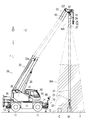
- the schematic diagram which shows the whole structure of the crane which concerns on one Embodiment of this invention.
- BRIEF DESCRIPTION OF THE DRAWINGS The schematic diagram which shows the whole structure of the guide information display apparatus which concerns on one Embodiment of this invention.
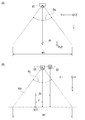
- field angle of a camera (A) Z axial direction view schematic diagram, (B) X axial direction view schematic diagram.
- FIG. 7A is a schematic view showing a data acquisition unit;
- FIG. 7A is a view looking up in the Y-axis direction;
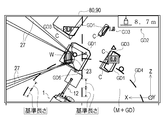
- FIG. 8A is a diagram showing a display state of guide information,
- FIG. 8A is a diagram showing a data display unit displaying an image M, and
- FIG. 8B is a diagram showing a data display unit showing an image M and guide information GD superimposed.
- a schematic diagram showing another configuration of the guide information display device (A) when the data processing unit, data display unit, and data input unit are constituted by a tablet PC, (B) data display unit, data input unit by touch panel display device If configured
- the schematic diagram which shows the relationship between a suspended load area
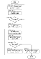
- FIG. 7 is a flowchart showing the flow of data processing by the data processing unit.
- the figure which shows the point-group data acquired by the data acquisition part (A) The figure which plotted the point-group data on a XYZ coordinate system, (B) The figure which divided the point-group data plotted on a XYZ coordinate system into several groups.
- Flow chart of the ground surface estimation method Explanatory drawing of the calculation method of the reference
- FIG. 7 is a flow diagram of a method of combining planes present in different groups.
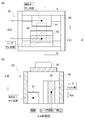
- Explanatory drawing of the coupling method of the plane which exists in a different group Explanatory drawing of the clustering process of the same area
- another same area cluster including all planar clusters whose elevation value difference is equal to or greater than a threshold is set.
- the crane 1 is an example of a crane provided with a guide information display device according to an embodiment of the present invention, and is a mobile crane that can move to a desired location.
- the crane 1 includes a traveling vehicle 10 and a crane device 20.
- the traveling vehicle 10 transports the crane device 20, has a plurality of (four in the present embodiment) wheels 11, and travels using an engine (not shown) as a power source.
- An outrigger 12 is provided at each of four corners of the traveling vehicle 10.
- the outrigger 12 is composed of an overhang beam 12a that can be extended hydraulically on both sides in the width direction of the traveling vehicle 10, and a hydraulic jack cylinder 12b that can extend in a direction perpendicular to the ground.
- the traveling vehicle 10 can bring the crane 1 into a workable state by grounding the jack cylinder 12b, and by increasing the extension length of the overhang beam 12a, the workable range of the crane 1 (work Radius) can be extended.
- the crane device 20 lifts the load W by a wire rope, and the swivel base 21, the telescopic boom 22, the main hook block 23, the sub hook block 24, the relief cylinder 25, the main winch 26, the main wire rope 27, the sub winch A sub wire rope 29 and a cabin 30 are provided.
- the swivel base 21 is configured to be able to pivot the crane apparatus 20, and is provided on the frame of the traveling vehicle 10 via an annular bearing.
- the annular bearing is disposed such that the center of rotation thereof is perpendicular to the installation surface of the traveling vehicle 10.
- the swivel base 21 is configured to be rotatable in one direction and the other direction with the center of the annular bearing as a rotation center.
- the swivel base 21 is rotated by a hydraulic swivel motor (not shown).
- the telescopic boom 22 supports the wire rope in a state in which the load W can be lifted.
- the telescopic boom 22 includes a plurality of base boom members 22a, second boom members 22b, third boom members 22c, force boom members 22d, fifth boom members 22e, and top boom members 22f. Each boom member is inserted in the order of the size of the cross-sectional area in a nested manner.
- the telescopic boom 22 is configured to be telescopic in the axial direction by moving each boom member with a telescopic cylinder (not shown).
- the telescopic boom 22 is provided so that the base end of the base boom member 22 a can swing on the swivel base 21.
- the telescopic boom 22 is configured to be horizontally rotatable and swingable on the frame of the traveling vehicle 10.
- the main hook block 23 is for hooking and suspending the hanging load W, and a plurality of hook sheaves around which the main wire rope 27 is wound and a main hook 32 for hanging the hanging load W are provided.
- the crane apparatus 20 further includes a sub hook block 24 for hooking and suspending the suspended load W in addition to the main hook block 23, and the sub hook block 24 is provided with a sub hook 33 for suspending the suspended load W. It is done.
- the relief cylinder 25 raises and lowers the telescopic boom 22 and holds the telescopic boom 22 in a posture.
- the relief cylinder 25 is composed of a hydraulic cylinder consisting of a cylinder portion and a rod portion.
- the main winch 26 is for carrying in (rolling up) and unwinding (rolling down) the main wire rope 27, and in the present embodiment, is constituted by a hydraulic winch.
- the main winch 26 is configured such that the main drum on which the main wire rope 27 is wound is rotated by the main hydraulic motor.
- the main winch 26 feeds the main wire rope 27 wound around the main drum by supplying the hydraulic fluid so that the main hydraulic motor rotates in one direction, and the main hydraulic motor rotates in the other direction.
- the main wire rope 27 is wound around the main drum and fed in by supplying the hydraulic oil.
- sub winch 28 is for carrying in and delivering the sub wire rope 29, and in the present embodiment, is constituted by a hydraulic winch.
- the cabin 30 covers a driver's seat 31 on which the operator is seated, and is provided on the side of the telescopic boom 22 in the swivel base 21.
- the crane 1 configured as described above can move the crane device 20 to an arbitrary position by causing the traveling vehicle 10 to travel, and causes the telescopic boom 22 to rise to an arbitrary elevation angle by the elevation cylinder 25.
- the telescopic boom 22 can be extended to any telescopic boom length.
- the crane 1 also includes a controller 34 that controls the operation of the swivel base 21, the telescopic boom 22, the relief cylinder 25 and the like (that is, the operation of the crane 1).
- the controller 34 can externally output information concerning the operation state of the swivel base 21, the telescopic boom 22, the hoisting cylinder 25, etc., information concerning the performance unique to the crane 1, the weight of the suspended load W, etc. .
- an XYZ coordinate system as shown in FIG. 1 is defined with reference to the axial direction of the fulcrum of the telescopic boom 22 (the same applies to the following description).
- the X-axis direction (also referred to as a lateral direction) is a horizontal direction parallel to the axial direction of the fulcrum of the telescopic boom 22.
- the Y-axis direction (also referred to as the elevation direction) is the vertical direction.
- the Z-axis direction (also referred to as the depth direction) is a horizontal direction perpendicular to the axial direction of the fulcrum of the telescopic boom 22. That is, the XYZ coordinate system is defined as a local coordinate system based on the telescopic boom 22, as shown in FIG.
- the crane 1 is provided with a guide information display device 50 as shown in FIG.
- the guide information display device 50 is an example of the guide information display device according to the present invention, and in order to enable the work by the crane 1 as shown in FIG. 1 to be performed efficiently and safely, the hanging load W It is a device for displaying information (hereinafter referred to as guide information) of an area including the following (hereinafter referred to as a hanging load area WA) as a video and presenting it to the operator.
- guide information information of an area including the following (hereinafter referred to as a hanging load area WA) as a video and presenting it to the operator.
- the “hanging load area WA” here is set as an area including the hanging load W in the Y-axis direction view in the working area SA of the crane 1, as shown in FIGS. 2 and 4. This is an area for which “guide information” is to be generated.
- the “suspended load area WA” is set as an area including immediately below the top boom member 22 f of the telescopic boom 22 in the crane 1, and the suspended load W, the ground surface F, and the feature C existing in the suspended load area WA are guides It becomes a measurement object by the information display device 50.
- the “suspended load area WA” is displaced in response to the turning operation, the raising and lowering operation, and the extension and contraction operation of the extension boom 22.
- the “guide information” referred to here is the operator about the quality of the telescopic boom 22 such as the length, the turning position, the ups and downs angle, the amount of unwinding of the wire rope when the operator transports the load W by the crane 1
- Image information of the suspended load area WA information pertaining to the shapes of the suspended load W and the feature C, height information of the suspended load W, height information of the feature C, and of the suspended load W It contains information related to flow lines.
- the guide information display device 50 is configured by a data acquisition unit 60, a data processing unit 70, a data display unit 80, and a data input unit 90.
- the data acquisition unit 60 is a part for acquiring data necessary for generating guide information in the suspended load area WA, and as shown in FIG. 3, the camera 61, the laser scanner 62, and the inertial measurement device (IMU) 63 Have.
- IMU inertial measurement device
- the data acquisition unit 60 is attached to the top boom member 22 f located at the tip of the telescopic boom 22 of the crane 1, and directly below the boom tip located directly above the load W It is placed in a state where it can catch the situation.
- “directly above” the suspended load W includes the position vertically above the suspended load W and the position of a certain range (for example, the range of the upper surface of the suspended load W) based on that position. It is a concept.
- the data acquisition unit 60 is attached to the top boom member 22f at the tip of the telescopic boom 22 via a gimbal 67 (see FIG. 1), and when the telescopic boom 22 performs a hoisting operation, a turning operation, and an telescopic operation.
- the attitude of the data acquisition unit 60 (the attitude in the Y-axis direction) can be maintained substantially constant.
- the camera 61 and the laser scanner 62 can always be directed to the load W.
- the data acquisition unit 60 can always acquire data from the suspended load W and the ground surface F (that is, the suspended load area WA) existing therebelow by the camera 61 and the laser scanner 62.
- the feature C exists in the suspended load area WA
- data of the feature C can be acquired by the camera 61 and the laser scanner 62.
- the camera 61 is a digital video camera for capturing an image of the suspended load area WA, and has a function of outputting the captured image to the outside in real time.
- the camera 61 has an angle of view (horizontal angle of view ⁇ h and vertical angle of view ⁇ v) as shown in FIGS. 5 (A) and 5 (B).
- the camera 61 has the number of pixels, the frame rate, and the image transmission rate in consideration of the amount of data necessary for generating appropriate guide information.
- the laser scanner 62 irradiates a laser to the object to be measured, and receives light reflected from the object to be measured by the laser, thereby acquiring information on the reflection point, and It is an apparatus for acquiring point cloud data.
- the objects to be measured by the laser scanner 62 are a load W, a feature C, and a ground surface F.
- a first GNSS receiver 65 for acquiring a measurement time is connected to the laser scanner 62.
- the laser scanner 62 acquires planar three-dimensional point cloud data in real time.
- the laser scanner 62 is provided with a total of 16 laser transmitting / receiving sensors, and it is possible to simultaneously irradiate 16 lasers to the measurement object to acquire point cloud data of the measurement object It is possible.
- the 16 laser transmitting / receiving sensors of the laser scanner 62 are disposed with different irradiation angles by 2 ° in the Z-axis direction, and irradiate the laser with a spread of 30 ° as a whole to the object to be measured. It is configured to be possible.
- each laser transmission / reception sensor of the laser scanner 62 is configured to be capable of rotating 360 degrees (all directions) around the Z axis.
- a locus drawn by a laser irradiated toward the suspended load area WA is referred to as a laser side line.
- the laser side line is parallel to the X-axis direction, and the laser scanner 62 simultaneously draws 16 laser side lines.
- the laser scanner 62 is disposed such that the laser side line is parallel to the X-axis direction. Further, in the laser scanner 62, a reference axis for changing the irradiation angle of the laser is parallel to the Z-axis direction.
- an inertial measurement unit (hereinafter referred to as IMU) 63 is a device for acquiring posture data of the camera 61 and the laser scanner 62 at the time of data acquisition.
- the IMU 63 can measure the attitude angle in real time, and has measurement accuracy that can be used to correct point cloud data acquired by the laser scanner 62.
- a second GNSS receiver 66 for obtaining measurement time is connected to the IMU 63.
- the data acquisition part 60 is a sensor unit which fixed the camera 61, the laser scanner 62, and inertial measurement device (IMU) 63 with respect to the frame body 64, and was comprised integrally.
- the frame body 64 is a substantially rectangular parallelepiped object configured by combining five plate members.
- the frame body 64 constitutes a rectangular parallelepiped side surface portion of four plate members, and the remaining one plate member constitutes an upper surface portion of the rectangular parallelepiped member and has an opening at the lower side.
- the camera 61 and the laser scanner 62 are attached to the inner side of the side surface of the frame 64, and the IMU 63 is attached to the upper surface of the frame 64.
- the image pickup device center position of the camera 61 and the laser center position of the laser scanner 62 are separated by a distance ⁇ zh in the Z-axis direction when viewed in the Y-axis direction.
- the laser center position is the rotation center of the laser in the laser scanner 62 and is located on the Z axis.
- the image pickup device center position of the camera 61 and the laser center position of the laser scanner 62 are separated by a distance ⁇ yv in the Y axis direction when viewed in the X axis direction.
- one of a pair of facing side surfaces of the four side surfaces of the frame body 64 is perpendicular to the Z axis, and the other of the facing pair of side surfaces is perpendicular to the X axis Will be placed in
- the data acquisition unit 60 is disposed in a posture in which the upper surface portion of the frame body 64 is perpendicular to the Y axis.
- the guide information display device 50 converts coordinate values between the XYZ coordinate system and the camera space coordinate system in order to superimpose guide information GD to be described later on the image M captured by the camera 61 and display the guide information GD on the data display unit 80. Do the processing.
- a three-dimensional camera space coordinate system Xc ⁇ Yc ⁇ Zc is defined in the video space of the camera 61.
- the distance in the X-axis direction from the vertical line extended from the lens center of the camera 61 to the point (x, y) is dh, and the maximum screen width in the horizontal direction of the camera 61 is wh.
- the point (x, y) has a position in the X axis direction from the screen center as x.
- the Xc coordinates of the point (x, y) in the camera space are expressed by the following Equations (1) and (2).
- the horizontal difference between the position of the imaging device of the camera 61 and the center of the laser is ⁇ zh (see FIG.
- the horizontal width of the camera image is wh
- the horizontal angle of view of the camera 61 is ⁇ h
- the temporary variable is tmp1.
- tmp1 (y ⁇ zh) ⁇ tan ( ⁇ ⁇ ⁇ h / 360) (1)
- Xc wh / 2-wh ⁇ x / (2 ⁇ tmp 1) (2)
- the Zc coordinates of the point (y, z) in the XYZ coordinate system into Zc coordinates in the camera space coordinate system will be described.
- the distance in the Z-axis direction from the point (y, z) to the laser center is dv
- the maximum screen width in the horizontal direction of the camera 61 is wv.
- the point (y, z) has a position in the Z-axis direction from the screen center as z.
- the Zc coordinates of the point (y, z) in the camera space are expressed by the following equations (3) and (4).
- the difference in the vertical direction between the image pickup element of the camera 61 and the position of the laser center of the laser scanner 62 is ⁇ yv (see FIG. 7B)
- the vertical width of the camera image is wv
- the vertical image of the camera 61 The angle is ⁇ v
- the temporary variable is tmp2.
- tmp2 Y ⁇ tan ( ⁇ ⁇ ⁇ v / 360)
- Zc wv / 2 + wv ⁇ (Z ⁇ yv) / (2 ⁇ tmp 2) (4)
- the guide information display device 50 converts the coordinates of point group data acquired by the laser scanner 62 or the like in the XYZ coordinate system into the camera space coordinate system using the above equations (1) to (4).
- the guide information GD is aligned and displayed on the image M taken at step.
- an apparatus capable of measuring the three-dimensional shape of the object to be measured is selected from the maximum reach height (for example, about 100 m) in consideration of the maximum reach height of the telescopic boom 22.
- an apparatus having predetermined performance for each specification such as measurement speed, number of measurement points, measurement accuracy, etc. in consideration of data amount and data accuracy necessary to generate appropriate guide information select.
- the case of using the laser scanner 62 provided with a total of 16 laser transmitting and receiving sensors is illustrated, but in the guide information display apparatus according to the present invention, the number of laser transmitting and receiving sensors constituting the laser scanner is used. It is not limited by. That is, in the guide information display apparatus according to the present invention, a laser scanner having an optimum specification is appropriately selected according to the maximum reach height of the boom (jib) of the crane and the like.
- the data acquired by the data acquisition unit 60 in the hanging load area WA includes the hanging load W, the ground surface F below the hanging load W, and an image obtained by photographing the feature C existing around the hanging load W by the camera 61 Contains data. Further, the data acquired in the suspended load area WA by the data acquiring unit 60 includes the suspended load W, the ground surface F, and point cloud data acquired by scanning the feature C with the laser scanner 62.
- the ground surface F mentioned here widely includes the surfaces to be the transfer source and the transfer destination of the hanging load W, and includes not only the ground surface but also the floor surface and roof surface of the roof of the building.
- the data processing unit 70 is a part for processing the data acquired by the data acquisition unit 60 to generate guide information GD to be presented to the operator, and in the present embodiment, predetermined data It is configured by a general-purpose personal computer in which a processing program is installed. Further, the data processing unit 70 is electrically connected to the controller 34 of the crane 1, and “crane information” output from the controller 34 is input to the data processing unit 70.
- the data display unit 80 is a part for displaying guide information GD to be presented to the operator, and includes a display device connected to the data processing unit 70. As shown in FIG. 8A, the data display unit 80 displays the video M of the suspended load area WA taken by the camera 61 in real time.
- a guide frame GD1 representing the external shape of the hanging load W and the feature C in the Y-axis direction view
- height information GD2 of the lower surface of the hanging load W ground
- the height information GD3 of the upper surface of the object C, the work radius line information GD4 indicating the flow line of the hanging load W, and the axis information GD5 indicating the axial direction of the telescopic boom 22 are included.
- the guide information GD generated by the data processing unit 70 and the video M are superimposed and displayed.
- the data input unit 90 is a part for inputting setting values and the like to the data processing unit 70, and is configured by a touch panel, a mouse, a keyboard device, and the like.
- the data processing unit 70, the data display unit 80, and the data input unit 90 are implemented by a tablet-type general purpose personal computer (hereinafter also referred to as a tablet PC). It is preferable to construct integrally.
- the data display unit 80 and the data input unit 90 are integrated by a touch panel display device, and the touch panel display device performs data processing as a general purpose PC.
- the unit 70 may be connected.
- the data display unit 80 and the data input unit 90 are disposed in a position in front of the driver's seat 31 in the cabin 30 at a position where the operator can easily view.
- the data processing unit 70 is preferably arranged in the vicinity of the data acquisition unit 60.
- the data processing unit 70, the data display unit 80, and the data input unit 90 are integrally configured by a tablet PC, the data processing unit 70 may be disposed in the cabin 30. Transmission of data between the data acquisition unit 60 and the data processing unit 70 is preferably performed by a wired LAN.
- the data transmission between the data acquisition unit 60 and the data processing unit 70 may adopt a wireless LAN or may adopt power line communication.
- the data processing unit 70, the data display unit 80, and the data input unit 90 are implemented by a tablet-type general purpose personal computer (hereinafter also referred to as a tablet PC). It is preferable to construct integrally.
- the data display unit 80 and the data input unit 90 are integrated by a touch panel display device, and the touch panel display device performs data processing as a general purpose PC.
- the unit 70 may be connected.
- the camera 61 continuously shoots the suspended load area WA, and acquires the image M of the suspended load area WA.
- point cloud data P point cloud data acquired by the laser scanner 62
- the point cloud data P is a set of point data p
- the point data p represents a point located on the ground surface F, the suspended load W, and the upper surface of the feature C existing in the suspended load area WA.
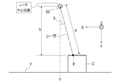
- the distance a from the measurement object (for example, the ground object C) to the laser scanner 62 and the irradiation angle b of the laser scanner 62 when the point data p is acquired. Information is included.
- the first GNSS receiver 65 is connected to the laser scanner 62, and while acquiring point cloud data P, the first GNSS receiver 65 receives time information from a plurality of positioning satellites Do. Then, the data processing unit 70 adds information related to the acquisition time of the point data p to the point data p. That is, the information related to the point data p includes the acquisition time tp in addition to the distance a and the irradiation angle b.
- the point cloud data P is acquired by the laser scanner 62, and at the same time, the attitude data Q of the laser scanner 62 is acquired by the IMU 63 at a predetermined cycle.
- the posture data Q includes information on the angle and acceleration with respect to each axial direction of the X, Y, and Z axes of the laser scanner 62.
- the acquisition cycle of the posture data Q by the IMU 63 is shorter than the acquisition cycle of the point cloud data P by the laser scanner 62.
- the posture data Q is a set of individual posture data q measured for each measurement cycle.
- a second GNSS receiver 66 is connected to the IMU 63 to acquire attitude data Q, and at the same time, the second GNSS receiver 66 receives time information from a plurality of positioning satellites.
- the data processing unit 70 assigns an acquisition time tq to the individual posture data q as information related to the acquisition time of the individual posture data q. That is, the information concerning the individual posture data q includes the acquisition time tq.
- the data processing unit 70 first, "frame extraction processing” is performed (STEP-101).
- the point cloud data P for one frame is cut out and output from the stream data of the point cloud data P.
- the point group data P for one frame is a set of point data p acquired while the irradiation direction of the laser by the laser scanner 62 makes one rotation around the Z axis.
- “synchronization processing of point cloud data and posture data” is performed (STEP-102).
- the data processing unit 70 synchronizes the point data p included in the point cloud data P for one frame with the attitude data Q acquired by the IMU 63. Specifically, in each point data p, the acquisition time tq of the individual posture data q closest to the acquisition time tp of the point data p is searched, and the individual posture data q at the acquisition time tq is Synchronize by matching to.
- the data processing unit 70 outputs point data p synchronized with the individual posture data q. Then, as shown in FIG. 11, the data processing unit 70 calculates the distance h from the laser center position of the laser scanner 62 to the point data p based on the distance a and the irradiation angle b.
- the “distance h” is the distance from the laser center position of the laser scanner 62 to the horizontal plane where the point data p exists, that is, the distance in the vertical direction from the laser center position of the laser scanner 62 to the point data p. is there.
- the data processing unit 70 performs correction using the individual posture data q corresponding to the point data p.
- the error caused by the attitude of the laser scanner 62 can be eliminated, and the distance h of the point data p can be calculated more accurately.
- the data acquisition unit 60 is provided with the IMU 63 for acquiring the attitude data Q of the laser scanner 62, and the data processing unit 70 is based on the attitude data Q of the laser scanner 62 acquired by the IMU 63.
- the point cloud data P is corrected.
- FIG. 13A shows point cloud data P (a set of point data p) viewed from the Z-axis direction.
- ground surface estimation processing is performed next (STEP-103).
- the data processing unit 70 performs processing to estimate the reference height H0 of the ground surface F present in the suspended load area WA.
- the data processing unit 70 first acquires point cloud data P for one frame.
- the point cloud data P is acquired from above the suspended load W and the feature C which are measurement objects, in the suspended load area WA including the suspended load W and the feature C and the ground surface F.
- the data processing unit 70 divides the suspended load area WA into a plurality of small areas S in a grid shape in plan view (view in the Y-axis direction) (area division process : STEP-201).
- the data processing unit 70 divides the laser side line at equal intervals by a dividing line parallel to the Z-axis direction, and divides it into small regions S having the same shape and the same area based on the divided laser side line doing.
- the data processing unit 70 divides the laser side line into ten parts to divide them into 160 small areas S.
- the data processing unit 70 extracts point data p having the largest distance h (the distance h is the maximum distance hmax) in each small area S (maximum point data extraction step: STEP-202). Point data p which is the maximum distance hmax is estimated to be point data p existing at the lowest position. Then, as shown in FIG. 14 and FIG. 15 (A), the data processing unit 70 calculates the separation amount D of the distance h of the other point data to the point data p which is the maximum distance hmax (a separation amount calculation step: STEP-203).
- the data processing unit 70 configures the ground surface F with point data p having a separation amount D within a predetermined threshold r1 (in this embodiment, a separation amount D within 7 cm) based on the maximum distance hmax. It extracts as point data (ground surface point data extraction process: STEP-204).
- the data processing unit 70 estimates the reference height H0 of the ground surface F of each small area S based on the distance h of the extracted point data p in each small area S (small area ground surface estimation step: STEP -205).
- the data processing unit 70 sets the average value of the distances h of the extracted point data p as the reference height H0 of the ground surface F in the small area S. With such a configuration, the data processing unit 70 can estimate the reference height H0 of the ground surface F in any small region S.
- the data processing unit 70 estimates the reference height H0 of the ground surface F of the suspended load area WA based on the reference height H0 of the ground surface F in each small area S (area ground surface estimation step: STEP-206). In the present embodiment, the data processing unit 70 further averages the reference height H0 (average value of the distance h) of the ground surface F in each small region S in all the small regions S as the ground surface of the suspended load region WA. The reference height H0 of F is used. With such a configuration, the data processing unit 70 can estimate the reference height H0 of the ground surface F of the suspended load area WA. Then, the data processing unit 70 calculates the elevation value H of the point data p from the distance h and the reference height H0. As shown in FIG. 10, the altitude value H is the height from the reference height H0 of the point data p.
- the data processing unit 70 determines that the difference between the reference height H0 of the ground surface F in one small area S and the reference height H0 of the ground surface F in the suspended load area WA is larger than a predetermined threshold.
- the point data p which does not constitute the ground surface F is determined to be extracted, and instead of the reference height H0 of the ground surface F in one small area S, the difference among the small areas S adjacent to the one small area S
- the reference height H0 of the ground surface F in the suspended load area WA may be corrected using the reference height H0 of the ground surface F of the small area S where the value of L falls below a predetermined threshold.
- the data processing unit 70 when it is estimated that point data p which does not constitute the ground surface F is extracted by such a configuration, a small area adjacent to one small area S instead of one small area S
- the reference height H0 of the ground surface F of the suspended load area WA can be more accurately estimated by using the reference height H0 of the ground surface F of the small area S in which the difference is less than the predetermined threshold among the regions S. .
- the reference height H0 of the ground surface F in the suspended load area WA in (STEP-206) it is estimated that point data p that does not constitute the ground surface F is extracted from all the small areas S. You may exclude the small area
- the data processing unit 70 can exclude the small area S estimated to be incapable of extracting point data constituting the ground surface F. Therefore, the reference height H0 in the suspended load area WA can be accurately estimated.
- the separation amount calculating step of calculating the separation amount D of the distance h of the other point data p to the point data p having the largest distance h, and in the small area S, the distance D of the distance h is
- the reference height H0 of the ground surface F of the small area S is estimated based on the ground surface point data extraction process of extracting the point data p within the predetermined threshold value r1 and the point data p extracted in the ground surface point data extraction process.
- Small territory It includes a ground surface estimating step, and a region ground surface estimating step of estimating the reference high
- the guide information display device 50 is configured to generate the guide information GD based on the reference height H0 of the ground surface F acquired accurately by the above processing. For this reason, in the guide information display device 50, the height information of the suspended load W and the height information of the feature C can be accurately calculated based on the reference height H0 of the ground surface F.
- the data processing unit 70 may be configured to automatically determine and designate the specific position on the video.
- the ground surface F to be a reference can be determined by designating the position of the ground surface in the data display unit 80 and the data input unit 90.
- the operator designates a clear position on the image displayed on the data display unit 80 as the ground surface.
- the data processing unit 70 generates a reference circle of a predetermined radius centered on the designated position (point), as shown in FIG.
- the data processing unit 70 detects an overlap with the point data p on the laser side line, and selects a plurality of point data p included in the reference circle.
- the data processing unit 70 first extracts point data p having the largest distance h (the distance h is the maximum distance hmax) from the plurality of selected point data p. . Then, the data processing unit 70 calculates the separation amount D of the distance h of the other point data to the point data p which is the maximum distance hmax.
- the data processing unit 70 configures the ground surface F as point data p whose distance D is within the predetermined threshold r1 (in this embodiment, distance D is within 7 cm) with reference to the maximum distance hmax. Extract as data.
- the data processing unit 70 estimates the reference height H0 of the ground surface F based on the distance h of the extracted point data p. In the present embodiment, the data processing unit 70 adopts the average value of the distances h of the extracted point data p as the reference height H0 of the ground surface F.
- “Plane estimation processing” is performed (STEP-104).
- the data processing unit 70 estimates the upper surfaces of the suspended load W and the feature C, which are measurement objects, present in the suspended load area WA by the upper surface estimation method described below.
- the point cloud data P for one frame is plotted on the suspended load area WA indicated by the XYZ coordinate system, as shown in FIG. 13A.
- the point cloud data P in such a suspended load area WA is schematically represented as shown in the upper diagram of FIG.
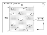
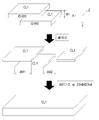
- the data processing unit 70 divides the point cloud data P acquired in the hanging load area WA as shown in the upper view of FIG. 17 into layers in the Y-axis direction with a predetermined thickness d as shown in the middle of FIG.
- the point cloud data P is distributed to a plurality of groups (see FIG. 13B).
- the data processing unit 70 assigns individual group IDs (here, IDs: 001 to 006) to the divided groups, and associates each point data p with the group ID.
- the data processing unit 70 estimates a plane by using a plurality of point data p included in the group.
- the “plane” referred to here is a plane which exists upward in the load W and the feature C, that is, the “upper surface” of the load W and the feature C.
- the data processing unit 70 selects two point data p ⁇ p from a plurality of point data p ⁇ p... Included in the same group, as shown in FIGS. (2 point selection process: STEP-301). Then, the data processing unit 70 calculates the distance L1 between two points of the selected two point data p ⁇ p as shown in FIG. 18 and the lower diagram of FIG. 19 (inter-point distance calculation step: STEP-302).
- the data processing unit 70 selects two points (two shown by dotted lines). One point data p ⁇ p) is considered to be on the same plane (two-point plane considering process: STEP-304). Then, the data processing unit 70 calculates the center of gravity G1 of each point (here, two selected points) considered to be on the same plane, as shown in FIGS. 18 and 20 (lower center calculation step: STEP-305). If it is determined as "no" in (STEP-303), the process returns to (STEP-301) to reselect two new points.
- the data processing unit 70 searches for point data p that is a nearby point with respect to the calculated center of gravity G1, as shown in FIG. 18 and the upper diagram in FIG. 21 (nearest point searching step: STEP-306).
- the “nearby point” referred to here is a point at which the distance between points with respect to the center of gravity G1 is equal to or less than the threshold value r2.
- the data processing unit 70 finds point data p that is a nearby point (STEP-307), the point data p that is the nearby point is the two points selected earlier. It is considered that it is on the same plane as the data p ⁇ p (near point plane considering step: STEP-308).
- the data processing unit 70 returns to (STEP-305) as shown in FIGS. 18 and 22 and the respective points regarded as being on the same plane (here, three points indicated by dotted lines).
- a new center of gravity G2 is calculated from the point data p ⁇ p ⁇ p).
- the data processing unit 70 proceeds to (STEP-306), and further searches for point data p which is a nearby point with respect to the gravity center G2. Then, as shown in FIG. 18 and the lower diagram of FIG. 22, if the data processing unit 70 further finds point data p that is a nearby point (STEP-307), the point data p that is a nearby point is also selected each point previously. And the point data p on the same plane as (step-308). Then, the data processing unit 70 searches for nearby points while calculating a new centroid, and repeats the processing from (STEP-305) to (STEP-308) in order until the point data p which is a nearby point is not detected. Do.
- the data processing unit 70 determines “no” in (STEP-307) and determines that the point is considered to be on the same plane if a new neighboring point is not found.
- Cluster a subset (cluster) of data p to estimate a plane (STEP-309).
- clustering divides point group data P, which is a set of point data p, into clusters so that point data p included in each cluster has a common feature of being on the same plane. It is a process.
- the data processing unit 70 divides the point cloud data P into point data p considered to be on the same plane, and sets a plane cluster CL1 (see the lower diagram in FIG. 17).
- each point data p belonging to the plane cluster CL1 it is possible to define a plane (that is, the “upper surface” of the hanging load W and the feature C).
- a plurality of plane clusters CL1 may exist in a group to which the same group ID is assigned.
- the data processing unit 70 estimates the "width" of the plane from the maximum value and the minimum value of the X coordinate of the point data p belonging to the plane cluster CL1, and the "depth” of the plane from the maximum value and the minimum value of the Z coordinate. Estimate The data processing unit 70 thus defines the plane formed by the plane cluster CL1.
- the plane defined here may be a polygon other than a rectangle.
- the top surfaces of the suspended load W and the ground object C can be estimated based on only the point cloud data P corresponding to the top surface acquired by the laser scanner 62. Therefore, in the upper surface estimation method described in the present embodiment, it is possible to estimate the upper surfaces of the hanging load W and the ground object C in a short time based on the point cloud data P acquired by the laser scanner 62. It is possible to estimate the upper surface of the load W and the feature C in real time.
- the top surfaces of the suspended load W and the feature C can be estimated without using a statistical method, and compared with the case where the statistical method is used, the suspended load W and the feature C It is possible to reduce the amount of calculation required to estimate the upper surface of. Therefore, in the upper surface estimation method described in the present embodiment, it is possible to estimate the upper surfaces of the suspended load W and the ground object C in a shorter time based on the point cloud data P acquired by the laser scanner 62.
- the data acquisition unit 60 is provided on the top boom member 22 f of the telescopic boom 22 in the crane 1, and the laser scanner 62 is used to Although the case of acquiring point cloud data P pertaining to the hanging load W, the ground object C, and the ground surface F from the vertically upper side is illustrated, the upper surface estimation method of the measurement object according to the present invention It is not limited as what is applied when making what exists around a suspended load into a measuring object.
- a laser scanner is provided at the boom tip portion or the drone of a work vehicle (for example, work vehicle etc.) provided with a boom, and exists vertically from below
- the present invention can be widely applied to the case of acquiring point cloud data of a measurement object and estimating the upper surface of the measurement object based on the acquired point cloud data.
- the data processing unit 70 combines the estimated planar clusters CL1 (upper surface).
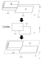
- the data processing unit 70 selects two plane clusters CL1 and CL1 to which different group IDs are assigned among the estimated plane clusters CL1, as shown in FIGS.
- the difference dH of the altitude value H is calculated (STEP-401: altitude value difference calculating step).
- the data processing unit 70 searches for a combination in which the difference dH is within the threshold value r3 (STEP-402).
- the altitude value H of the plane cluster CL1 mentioned here is an average value of the altitude values H of the point data p belonging to the plane cluster CL1.
- the data processing unit 70 determines the combination of those planar clusters CL1 ⁇ .
- the overlap dW in the X-axis direction is detected for CL1 (STEP-403: overlap detection step).
- overlap refers to the overlap degree and separation degree in the X-axis direction of the plane defined by the plane cluster CL1, and as shown in FIGS. 24 and 25, the overlap amount dW1 of “width” is detected. In the case (dW1> 0) or when the separation amount dW2 is equal to or less than the predetermined threshold value r4 (0 ⁇ dW2 ⁇ r4), “overlap” is detected.
- the data processing unit 70 repeats the above processing until the combination of planar clusters CL1 and CL1 satisfying the condition disappears (STEP-406), and a plane existing across a plurality of groups is displayed. presume.
- the data processing unit 70 outputs the plane (that is, plane cluster CL1) coupled by the above coupling process.
- the plane defined by the plane cluster CL1 is a plane facing upward in the load W and the feature C, that is, the upper surface of the load W and the feature C.
- Such a plane estimation method can estimate a plane without using a normal vector of the point cloud data P. For this reason, there is a feature that the amount of calculation can be reduced compared to the case of estimating a plane using a normal vector of the point cloud data P.
- the hanging load W or the ground can be obtained without acquiring point data p of the side surface of the hanging load W or the feature C. The three-dimensional shape of the object C can be grasped.
- clustering processing of the same area is performed (STEP-105).
- clustering divides point cloud data P, which is a set of data, into clusters so that point data p included in each cluster has a common feature of being in the “same area”. It is a process.
- the generated plane cluster CL1 (plane) is clustered from different viewpoints of whether or not it exists in the “same area” regardless of whether or not it configures the same plane. It is a process.
- the data processing unit 70 includes a plane cluster CL1 including point data p whose elevation value H is the maximum value Hh, and a plane cluster not coupled to the plane cluster CL1. Extract CL1. Then, the data processing unit 70 calculates the difference ⁇ H of the altitude values H of the extracted planar clusters CL1, and if the difference ⁇ H is equal to or less than a predetermined threshold, the process proceeds to the next determination.
- the data processing unit 70 confirms overlap in the Y-axis direction for two plane clusters CL1 and CL1 whose difference ⁇ H is less than or equal to a predetermined threshold.
- the data processing unit 70 “same area” as shown in the lower diagram of FIG.
- These planar clusters CL1 and CL1 form the same area cluster CL2.
- the data processing unit 70 further searches the plane cluster CL1 including the point data p having the maximum value Hh of the elevation value H and the plane cluster CL1 not coupled to the plane cluster CL1, and the plane cluster CL1 is not coupled. If is extracted, the judgment based on the difference ⁇ H and the confirmation of the overlap in the Y-axis direction are performed, and if there is a plane cluster CL1 meeting the above condition, it is further added to the same area cluster CL2.
- the data processing unit 70 repeats such processing until the unjoined planar cluster CL1 is not found with respect to the planar cluster CL1 including the point data p having the maximum value Hh of the elevation value H.
- the data processing unit 70 forms the same area cluster CL2 by the above processing.
- the point data p belonging to the same area cluster CL2 formed in this way is treated as having one shape in shape in the display of the guide information GD described later, so as to surround the same area cluster CL2.
- the guide frame GD1 is displayed.
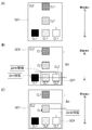
- Such “clustering process of the same area” is preferably hierarchical clustering using a tree structure based on elevation values as shown in FIGS. 27 (A) and 27 (B).
- the data processing unit 70 creates a tree structure using the elevation value H for each feature C in the “clustering process of the same area”.
- the hierarchical clustering using the tree structure is performed on the feature C of the first example shown in FIG. 27 (A)
- the feature C of the second example shown in FIG. 27 (B) An example of hierarchical clustering using a tree structure is illustrated.
- the data processing unit 70 sets a plane cluster CL1 having the smallest average value of the elevation values H as a "root”. In addition, if there is a plane cluster CL1 having an overlap in the Y-axis direction view with respect to the plane cluster CL1 configuring the “root”, the data processing unit 70 extends the “branch” from the “root” At the tip of the branch, a planar cluster CL1 having the overlap is added. Then, the data processing unit 70 sets the plane cluster CL1 having the largest average value of the elevation values H as a “child”.
- the data processing unit 70 acquires the tree structure of the feature C created in the “clustering process of the same area”. Then, the data processing unit 70 acquires point data p included in each plane cluster CL1 configuring the tree structure. Next, as shown in the upper diagram of FIG. 28, the data processing unit 70 obtains point data p on the laser side line located farthest in the Z-axis direction from the point data p of the “child” plane cluster CL1. Do. Then, the data processing unit 70 creates a rectangle having a width in the X-axis direction which is separated in the Z-axis direction by a half of the distance to the adjacent laser side line and can surround each point data p. .
- the data processing unit 70 includes all point data p on the corresponding laser side line as shown in the lower part of FIG. Transform the rectangle to create an outline. Then, the data processing unit 70 searches for the point data p on the adjacent laser side line until the point data p on the target laser side line disappears, and repeats the above processing. Finally, the data processing unit 70 creates an outline that externally wraps all planar clusters CL1 included in the selected tree structure.
- the data processing unit 70 outputs only the outline that meets the conditions as the guide frame GD1 out of the generated outlines.
- the conditions to be output as the guide frame GD1 for example, as shown in FIG. 29A, it is possible to select the conditions for displaying only the outline of the feature C, which is a large frame. When this condition is selected, one guide frame GD1 surrounding the entire feature C is displayed for the feature C on the data display unit 80.
- the difference (difference .DELTA.H) of the elevation value H with respect to the "root" is Among the outlines (small frames) which are equal to or greater than the threshold value, it is possible to select a condition for displaying the outline relating to the plane cluster CL1 having the highest elevation value H in each branch.
- the data display unit 80 displays a first guide frame GD1 surrounding the entire feature C and a second guide frame included inside the first guide frame GD1.
- the guide frame GD1 is displayed, and more detailed guide information GD in which the three-dimensional shape of the feature C is considered is displayed.
- the difference (difference ⁇ H) of the elevation value H with respect to the “root” is It is possible to select a condition for displaying all the outlines (small frames) which are equal to or larger than the threshold. Even when this condition is selected, the data display unit 80 displays the first guide frame GD1 surrounding the entire feature C and the second guide frame GD1 included therein, and the ground More detailed guide information GD in which the three-dimensional shape of the object C is considered is displayed.
- Such display conditions can also be performed by adjusting the threshold value of the difference ⁇ H.
- the operator can appropriately select the display conditions of the guide frame GD1 so that the display of the guide information GD can be more easily viewed.
- the guide frame GD1 representing the feature C in more detail in consideration of the three-dimensional shape of the feature C is generated by generating the guide frame GD1 based on the same area cluster CL2. It is possible to generate. Further, in the guide information display device 50, it is possible to generate a guide frame GD1 which collectively encloses the planar cluster CL1 present in the same area. That is, according to the guide information display device 50, it is possible to present more detailed and easy-to-view guide information GD.
- synchronization processing of point cloud data and camera image is performed (STEP-106).
- the point cloud data P acquired in the XYZ coordinate system is converted into coordinate values in the camera space coordinate system and synchronized with the image M captured by the camera 61 ( Alignment) and output to the data display unit 80.
- “guide display processing” is performed next (STEP-107).
- the data processing unit 70 generates guide information GD based on the generated information of the same area cluster CL 2, and outputs the guide information GD to the data display unit 80.
- "crane information” output from the controller 34 of the crane 1 is used.
- the “crane information” used here includes information on the length of the telescopic boom 22, the elevation angle, the working radius of the crane 1, the weight of the hanging load W, and the like.
- the guide information GD can be generated by accurately grasping the three-dimensional shape of.
- Such a configuration is suitable for the purpose of grasping the shapes of the hanging load W and the ground object C in real time because the amount of data computation can be small, and the data processing unit 70 with a simple hardware configuration can be used .
- the data display unit 80 displays the guide information GD.
- the guide information GD displayed by the data display unit 80 includes information relating to the designated position of the ground surface F by the operator as shown in FIG. 8 (B).
- the hanging load W can be designated.
- the plane (upper surface) present at the designated position is set as representing the upper surface of the hanging load W.
- the guide frame GD1 according to the hanging load W and the guide frame GD1 according to the feature C be displayed by changing the line color, the line thickness, and the like.
- the information which concerns on the ground surface F and the designated position of the hanging load W is displayed by the marker represented with figures, such as a circle.
- the guide information GD displayed by the data display unit 80 includes the guide frame GD1 generated by the data processing unit 70.
- the data processing unit 70 outputs the guide frame GD1 based on the set same area cluster CL2.
- the data processing unit 70 can provide a margin for reliably avoiding a collision as the guide frame GD1 of the hanging load W, and a frame offset outward from the outline of the hanging load W by a predetermined distance.
- the line can be output as a guide frame GD1.
- Such a guide frame GD1 is a frame display in which the upper surface (planar cluster CL1) estimated in the hanging load W and the feature C is surrounded by line segments.
- the guide information GD displayed by the data display unit 80 includes height information GD2 from the reference height H0 to the lower surface of the hanging load W and height information GD3 from the reference height H0 to the upper surface of the feature C. include.
- the height information GD2 of the hanging load W be configured to be provided with an independent area at an easily viewable position on the screen of the data display unit 80 and to be displayed in the area.
- the height information GD2 of the hanging load W and the height information GD3 of the feature C are not mistaken.
- the data processing unit 70 calculates the height information GD2 by subtracting the height of the suspended load W from the upper surface height of the plane cluster CL1 estimated to be the upper surface of the suspended load W.
- the operator inputs information related to the suspended load W (hereinafter referred to as “suspended load information”) to the data processing unit 70 in advance.
- the operator inputs the "hanging load information” from the data input unit 90.
- the data processing part 70 acquires the height of the hanging load W using "hanging load information.”
- the height information GD3 of the feature C is displayed inside the guide frame GD1 surrounding the feature C.
- the guide frame GD1 is configured to be displayed so as to partially overlap the guide frame GD1.
- the correspondence between the feature C and the height information GD3 is clarified by such a configuration.
- the data processing unit 70 changes the line color of the guide frame GD1 in accordance with the elevation value H of the flat cluster CL1 corresponding to the guide frame GD1.
- the guide information display device 50 with such a configuration, when the operator looks at the guide frame GD1, the rough elevation value (height) of the hanging load W or the feature C can be perceived sensuously. For this reason, in the guide information display device 50, the heights of the hanging load W and the feature C can be more accurately presented.
- the data processing unit 70 changes the font color of the height information GD2 in accordance with the elevation value H of the plane cluster CL1 corresponding to the guide frame GD1.
- the operator can perceptually perceive rough elevation values (heights) of the suspended load W and the feature C by looking at the height information GD2. For this reason, in the guide information display device 50, the heights of the hanging load W and the feature C can be more accurately presented.
- the display of the guide information GD performed by the guide information display device 50 includes flow line information of the hanging load W.
- the movement line information of the hanging load W includes work radius line information GD4 of the crane 1 and axis information GD5 of the telescopic boom 22 of the crane 1.
- the "flow line information of the hanging load W" may be replaced with "flow line information of the main hook 32", and the work radius line information GD4 and the axis line information GD5 may be "flow line of the main hook 32". It can also be used as information.
- the work radius line information GD4 is an indicator of the flow line of the suspended load W when the telescopic boom 22 is turned, and the suspended load W moves along an arc shown as the work radius line information GD4.
- the axis information GD5 is an indicator of the flow line of the suspended load W when the telescopic boom 22 is moved up and down and extends and retracts, and the suspended load W moves along a straight line indicated as the axis information GD5.
- the working radius R of the crane 1 is the horizontal distance from the turning center of the telescopic boom 22 in the crane 1 to the vertical line passing through the center of the main hook 32 (in this embodiment, the lens center of the camera 61).
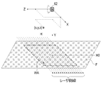
- an XYZ coordinate system as shown in FIG. 32 is defined with reference to the origin O1 of the camera coordinate system (the lens center of the camera 61).
- the X-axis direction is a horizontal direction parallel to the axial direction of the fulcrum of the telescopic boom 22.
- the Y-axis direction is the vertical direction.
- the Z-axis direction is a horizontal direction perpendicular to the axial direction of the fulcrum of the telescopic boom 22.
- the turning center of the telescopic boom 22 expressed with the origin O1 of the camera coordinate system as a reference is O2 (x1, y1, z1)
- the working radius R can be calculated by the following equations (5) and (6).
- the temporary variable is tmp3.
- the data processing unit 70 may use the working radius R input as “crane information” from the crane 1 in addition to the case where the working radius R is calculated based on the above formulas (5) and (6).
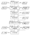
- the data processing unit 70 acquires an image M photographed by the camera 61 (photographing step: STEP-501).
- the image M of the camera 61 is suspended at least from the load W and the ground surface F from above the load W lifted by the crane 1 provided with the telescopic boom 22 capable of turning, raising and lowering and telescopic movement. It is acquired in the load area WA.
- the data processing unit 70 acquires point cloud data P for one frame (point cloud data acquisition step: STEP-502).
- the point cloud data P is acquired from above the suspended load W in the suspended load area WA including at least the suspended load W and the ground surface F.
- the data processing unit 70 performs an arbitrary small area S (for example, a predetermined small area S intersecting the perpendicular extending from the lens center of the camera 61) or the small area S by the ground surface estimation process described above (see FIGS. 14 to 16) or The reference height H0 of the ground surface F of the suspended load area WA is estimated (ground surface estimation step: STEP-503).
- an arbitrary small area S for example, a predetermined small area S intersecting the perpendicular extending from the lens center of the camera 61
- the reference height H0 of the ground surface F of the suspended load area WA is estimated (ground surface estimation step: STEP-503).
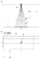
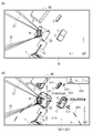
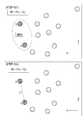
- the data processing unit 70 based on the reference height H0 of the ground surface F, as shown in the upper view of FIG. 30, the upper view of FIG. 31, and FIG. Calculate wv (shooting range calculation step: STEP-504).
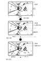
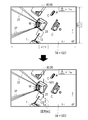
- the data processing unit 70 calculates the turning center of the crane 1 with respect to the imaging range of the camera 61 from the origin O1 and the working radius R of the camera coordinate system as shown in the middle of FIG. Then, as shown in FIG. 30 lower view and FIG. 33, the data processing unit 70 generates work radius line information GD4 which is the guide information GD from the swing center point O2 of the crane 1 and the work radius R (flow line information generation process : STEP-505).
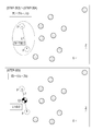
- the data processing unit 70 passes through the points O1 and O2 based on the origin O1 of the camera coordinate system and the turning center point O2 of the telescopic boom 22. From the above, the axial direction of the telescopic boom 22 is calculated to generate axis information GD5 which is guide information GD.
- axis information GD5 which is guide information GD.
- either of the work radius line information GD4 and the axis line information GD5 may be generated first by the data processing unit 70. Further, in (STEP-405), only one of the work radius line information GD4 and the axis line information GD5 may be generated.
- the data processing unit 70 outputs the work radius line information GD4 to the data display unit 80 as shown in FIG. 30B and FIG. 33, and the work radius line information GD4 is superimposed on the image M in the data display unit 80.
- display flow line information display process: STEP-506).
- the data processing unit 70 outputs the axis line information GD5 to the data display unit 80 as shown in FIG. 31 lower view and FIG. Is superimposed and displayed.
- the axial line information GD5 is displayed along the Z-axis direction.
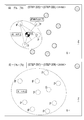
- the work radius line information GD4 and the axis line information GD5 may be simultaneously displayed on the data display unit 80 as shown in FIG.
- the data processing unit 70 outputs a line for displaying the work radius line information GD4 and the axis line information GD5 by a broken line as shown in the lower side of FIG. 30 and the lower side of FIG.
- the length and the interval are set according to the height (the imaging range) of the data acquisition unit 60 calculated based on the reference height H0 of the ground surface F.
- the length of a broken line and a length (hereinafter referred to as a reference length) as an indication of the interval are set.
- the work radius information GD4 and the axis line information GD5 are determined according to the height (the size of the imaging range) of the data acquisition unit 60 calculated based on the reference height H0 of the ground surface F.
- the length and interval of the broken line are changed, and on the scale at that time, it is displayed as the length and interval corresponding to 1 m on the ground surface F. That is, as the height of the data acquisition unit 60 increases, the length and interval of the broken line on the display shorten, and as the height of the data acquisition unit 60 decreases, the length and interval of the broken line on the display increase.
- the operator can display the ground surface F from the guide information GD by displaying the lengths and intervals of the broken lines of the work radius line information GD4 and the axis line information GD5 in the reference lengths.
- the sense of distance to the object to be measured can be easily grasped.
- the reference height H0 of the ground surface F around the suspended load W is calculated using the ground surface estimation processing, and the imaging range of the camera 61 is calculated based on the reference height H0 of the ground surface F.
- the method of calculating the imaging range is not limited to this.
- the imaging range of the camera 61 may be calculated based on the height of the camera 61 with respect to the installation surface of the crane 1 calculated from “crane information”. Further, as long as the camera 61 has a zoom function, the imaging range of the camera 61 may be calculated in consideration of the zoom magnification.
- the guide information display apparatus is suspended by the main wire rope 27 suspended from the telescopic boom 22 and is moved from above the suspended load W moved according to the operation of the telescopic boom 22
- the data acquisition unit 60 including the laser scanner 62 to acquire the data display unit 80 that displays the image M of the camera 61, and the point cloud data P acquired by the laser scanner 62
- the data processing unit 70 generates the guide information GD to be displayed in an overlapping manner, and the data processing unit 70 determines the reference height H of the ground surface F based on the point cloud data P acquired by the laser scanner 62.
- the display of the guide information GD performed by the guide information display device 50 includes an alarm display for preventing contact between the load W and the feature C.
- the horizontal distance when projecting the hanging load W and the feature C on a horizontal plane is equal to or less than a predetermined threshold (for example, 1 m), and the distance in the vertical direction is a predetermined threshold (for example, 1 m) If it is the following, it is determined that there is a risk of contact.
- the data processing unit 70 guides the guide frame GD1 of the feature C and the guide frame GD1 of the feature C in such a manner as to emphasize the guide frame GD1 and height information GD2 of the feature C which may come into contact with the load W. Output height information GD2.
- the data processing unit 70 outputs the guide frame GD1 of the feature C and the height information GD2 in a mode in which the guide frame GD1 and the height information GD2 of the feature C blink.
- the data processing unit 70 outputs the guide frame GD1 and the height information GD2 of the feature C as an alarm display, and displays them on the data display unit 80, whereby the operator's attention can be urged. .
- the exclusion area JA is set between the suspended load W and the top boom member 22f. Then, the data processing unit 70 is configured to exclude point data p acquired in the excluded area JA from the data processing target.
- the main wire rope 27 passes through the exclusion area JA.
- the guide information display device 50 is configured to present more accurate and easy-to-see guide information GD by not including the main wire rope 27 in the generation target (measurement object) of the guide information GD.
- the excluded area JA should be set at a position separated by a predetermined distance from the upper surface of the suspended load W in consideration of not affecting the generation of the guide frame GD1 of the suspended load W. Is preferred.
- a guide frame GD1 indicating the shape of the suspended load W and the feature C existing around the suspended load W and the height for the operator of the crane 1 is shown.
- the guide information GD including the height information GD2 and GD3 can be accurately presented.
- the operator can use the guide information GD presented by the guide information display device 50. Based on the work by the crane 1 can be performed efficiently and safely.
- the present invention is applicable to a guide information display device, a crane and a method of generating guide information.
Landscapes
- Engineering & Computer Science (AREA)
- Mechanical Engineering (AREA)
- Automation & Control Theory (AREA)
- Control And Safety Of Cranes (AREA)
- Jib Cranes (AREA)
Abstract
La présente invention fournit des informations de guidage qui représentent précisément le chemin de déplacement d'une charge de levage. Un dispositif d'affichage d'informations de guidage est équipé : d'une unité d'acquisition de données pourvue d'une caméra qui capture une image d'une région contenant au moins une charge de levage et la surface de sol d'au-dessus de la charge de levage qui se déplace selon le fonctionnement d'une flèche et est suspendue à un câble suspendu à la flèche, et pourvue également d'un dispositif de balayage laser pour acquérir un groupe de points de données d'au-dessus de la charge de levage dans ladite région ; d'une unité d'affichage de données pour afficher l'image de caméra ; et d'une unité de traitement de données pour générer des informations de guidage à afficher d'une manière chevauchante sur l'image de caméra, sur la base du groupe de points de données acquis par le dispositif de balayage laser. L'unité de traitement de données estime la hauteur standard de la surface de sol sur la base du groupe de points de données acquis par le dispositif de balayage laser, calcule la plage d'imagerie de caméra sur la base de la hauteur standard de la surface de sol, et génère des informations de guidage exprimant le chemin de déplacement de la charge de levage sur la base de la plage d'imagerie de caméra.
Applications Claiming Priority (2)
| Application Number | Priority Date | Filing Date | Title |
|---|---|---|---|
| JP2017-142202 | 2017-07-21 | ||
| JP2017142202A JP6832806B2 (ja) | 2017-07-21 | 2017-07-21 | ガイド情報表示装置、クレーンおよびガイド情報の生成方法 |
Publications (1)
| Publication Number | Publication Date |
|---|---|
| WO2019017472A1 true WO2019017472A1 (fr) | 2019-01-24 |
Family
ID=65016596
Family Applications (1)
| Application Number | Title | Priority Date | Filing Date |
|---|---|---|---|
| PCT/JP2018/027280 Ceased WO2019017472A1 (fr) | 2017-07-21 | 2018-07-20 | Dispositif d'affichage d'informations de guidage, grue et procédé de génération d'informations de guidage |
Country Status (2)
| Country | Link |
|---|---|
| JP (1) | JP6832806B2 (fr) |
| WO (1) | WO2019017472A1 (fr) |
Cited By (1)
| Publication number | Priority date | Publication date | Assignee | Title |
|---|---|---|---|---|
| CN116524024A (zh) * | 2023-04-28 | 2023-08-01 | 深圳鲲云信息科技有限公司 | 基于单目摄像头的安全检测方法、计算机设备和存储介质 |
Families Citing this family (3)
| Publication number | Priority date | Publication date | Assignee | Title |
|---|---|---|---|---|
| JP7351231B2 (ja) * | 2020-02-10 | 2023-09-27 | 株式会社タダノ | 吊荷監視装置、クレーン、吊荷監視方法及びプログラム |
| JP7511510B2 (ja) * | 2021-03-12 | 2024-07-05 | 日立建機株式会社 | 作業機械 |
| JP7753918B2 (ja) * | 2022-02-21 | 2025-10-15 | 株式会社タダノ | クレーンの操縦支援システム及び操縦支援システムを有するクレーン |
Citations (3)
| Publication number | Priority date | Publication date | Assignee | Title |
|---|---|---|---|---|
| JP2013018580A (ja) * | 2011-07-08 | 2013-01-31 | Tadano Ltd | 性能線表示装置 |
| JP2013120176A (ja) * | 2011-12-09 | 2013-06-17 | Tadano Ltd | 吊荷周辺の物体の高さ情報通知システム |
| JP2016153335A (ja) * | 2015-02-20 | 2016-08-25 | 株式会社タダノ | 吊荷監視装置 |
-
2017
- 2017-07-21 JP JP2017142202A patent/JP6832806B2/ja active Active
-
2018
- 2018-07-20 WO PCT/JP2018/027280 patent/WO2019017472A1/fr not_active Ceased
Patent Citations (3)
| Publication number | Priority date | Publication date | Assignee | Title |
|---|---|---|---|---|
| JP2013018580A (ja) * | 2011-07-08 | 2013-01-31 | Tadano Ltd | 性能線表示装置 |
| JP2013120176A (ja) * | 2011-12-09 | 2013-06-17 | Tadano Ltd | 吊荷周辺の物体の高さ情報通知システム |
| JP2016153335A (ja) * | 2015-02-20 | 2016-08-25 | 株式会社タダノ | 吊荷監視装置 |
Cited By (1)
| Publication number | Priority date | Publication date | Assignee | Title |
|---|---|---|---|---|
| CN116524024A (zh) * | 2023-04-28 | 2023-08-01 | 深圳鲲云信息科技有限公司 | 基于单目摄像头的安全检测方法、计算机设备和存储介质 |
Also Published As
| Publication number | Publication date |
|---|---|
| JP6832806B2 (ja) | 2021-02-24 |
| JP2019023116A (ja) | 2019-02-14 |
Similar Documents
| Publication | Publication Date | Title |
|---|---|---|
| WO2019017458A1 (fr) | Dispositif d'affichage d'informations de guidage, grue équipée de ce dispositif, et procédé d'affichage d'informations de guidage | |
| JP7008851B2 (ja) | ガイド情報表示装置、ガイド情報表示方法、および作業機 | |
| WO2019017455A1 (fr) | Dispositif d'affichage d'informations de guidage et grue | |
| JP6871097B2 (ja) | ガイド情報表示装置およびこれを備えた作業機およびガイド情報表示方法 | |
| WO2019017430A1 (fr) | Procédé d'estimation de surface supérieure de cible de mesure, dispositif d'affichage d'informations de guidage et grue | |
| JP6907061B2 (ja) | 測定対象物の上面推定方法、ガイド情報表示装置およびクレーン | |
| WO2019017469A1 (fr) | Procédé d'estimation de surface de sol, dispositif d'affichage d'informations de guidage et grue | |
| WO2019017472A1 (fr) | Dispositif d'affichage d'informations de guidage, grue et procédé de génération d'informations de guidage |
Legal Events
| Date | Code | Title | Description |
|---|---|---|---|
| 121 | Ep: the epo has been informed by wipo that ep was designated in this application |
Ref document number: 18834815 Country of ref document: EP Kind code of ref document: A1 |
|
| NENP | Non-entry into the national phase |
Ref country code: DE |
|
| 122 | Ep: pct application non-entry in european phase |
Ref document number: 18834815 Country of ref document: EP Kind code of ref document: A1 |