WO2019021359A1 - Matériau d'isolation thermique sous vide, boîte d'isolation thermique, et procédé de fabrication dudit matériau d'isolation thermique sous vide - Google Patents
Matériau d'isolation thermique sous vide, boîte d'isolation thermique, et procédé de fabrication dudit matériau d'isolation thermique sous vide Download PDFInfo
- Publication number
- WO2019021359A1 WO2019021359A1 PCT/JP2017/026778 JP2017026778W WO2019021359A1 WO 2019021359 A1 WO2019021359 A1 WO 2019021359A1 JP 2017026778 W JP2017026778 W JP 2017026778W WO 2019021359 A1 WO2019021359 A1 WO 2019021359A1
- Authority
- WO
- WIPO (PCT)
- Prior art keywords
- heat insulating
- vacuum heat
- insulating material
- heat insulation
- vacuum
- Prior art date
- Legal status (The legal status is an assumption and is not a legal conclusion. Google has not performed a legal analysis and makes no representation as to the accuracy of the status listed.)
- Ceased
Links
Images


Classifications
-
- F—MECHANICAL ENGINEERING; LIGHTING; HEATING; WEAPONS; BLASTING
- F16—ENGINEERING ELEMENTS AND UNITS; GENERAL MEASURES FOR PRODUCING AND MAINTAINING EFFECTIVE FUNCTIONING OF MACHINES OR INSTALLATIONS; THERMAL INSULATION IN GENERAL
- F16L—PIPES; JOINTS OR FITTINGS FOR PIPES; SUPPORTS FOR PIPES, CABLES OR PROTECTIVE TUBING; MEANS FOR THERMAL INSULATION IN GENERAL
- F16L59/00—Thermal insulation in general
- F16L59/06—Arrangements using an air layer or vacuum
- F16L59/065—Arrangements using an air layer or vacuum using vacuum
-
- Y—GENERAL TAGGING OF NEW TECHNOLOGICAL DEVELOPMENTS; GENERAL TAGGING OF CROSS-SECTIONAL TECHNOLOGIES SPANNING OVER SEVERAL SECTIONS OF THE IPC; TECHNICAL SUBJECTS COVERED BY FORMER USPC CROSS-REFERENCE ART COLLECTIONS [XRACs] AND DIGESTS
- Y02—TECHNOLOGIES OR APPLICATIONS FOR MITIGATION OR ADAPTATION AGAINST CLIMATE CHANGE
- Y02B—CLIMATE CHANGE MITIGATION TECHNOLOGIES RELATED TO BUILDINGS, e.g. HOUSING, HOUSE APPLIANCES OR RELATED END-USER APPLICATIONS
- Y02B80/00—Architectural or constructional elements improving the thermal performance of buildings
- Y02B80/10—Insulation, e.g. vacuum or aerogel insulation
Definitions
- the present invention relates to a vacuum heat insulating material used as a heat insulating material for a refrigerator or the like, a heat insulating box, and a method of manufacturing the vacuum heat insulating material.
- a conventional vacuum heat insulating material of this type has a core material and an adsorbent for adsorbing moisture or gas covered with an outer packaging material, and the inside of the outer packaging material is decompressed to near vacuum and sealed (for example, Patent Document 1).
- a reduction in the degree of vacuum inside the outer packaging material leads to a reduction in the heat insulation performance.
- moisture is released from the core material after depressurizing and sealing the inside of the outer packaging material by previously drying the core material in the drying furnace before inserting the core material into the outer packaging material.
- the degree of vacuum inside the outer packaging material is increased, and the decrease in heat insulation performance is suppressed.
- Patent Document 1 drying is performed before inserting the core material into the outer packaging material, but the amount of water removed from the core material by drying in the drying furnace depends on the relative humidity in the drying furnace. Since the relative humidity in the drying oven changes depending on the season and the weather, the amount of water removed from the core also changes. Therefore, after the inside of the outer packaging material into which the core material is inserted is sealed under reduced pressure, the amount of water released from the core material into the outer packaging material also varies. As a result, there has been a problem that the degree of vacuum inside the outer packaging material varies depending on the season, the weather, etc., and the variation in the heat insulating performance of the vacuum heat insulating material becomes large.
- the present invention has been made to solve the problems as described above, and it is an object of the present invention to provide a vacuum heat insulating material, a heat insulating box and a method of manufacturing the vacuum heat insulating material with less variation in heat insulating performance.
- the vacuum heat insulating material according to the present invention comprises a core material for holding a vacuum space, a hydroxide, and an outer packaging material for covering the core material and the hydroxide, and the inside of the outer packaging material is decompressed and sealed
- the weight of the hydroxide is at least 0.01 times the weight of the core material.
- the heat insulation box which concerns on this invention is equipped with said vacuum heat insulating material.
- a core material for holding a vacuum space and an oxide are covered with an outer packaging material and sealed to form a sealed body, and the sealed body is heat-treated. And a step of decompressing and sealing the inside of the outer packaging material of the sealed body.
- the weight of the hydroxide in the outer wrapping material is 0.01 times or more of the weight of the core material, it is possible to obtain a vacuum heat insulating material and a heat insulating box with less variation in heat insulating performance.
- the core material is coated with the outer packaging material and then subjected to heat treatment, it is possible to realize uniform drying of the core material without depending on the relative humidity of the heat treatment furnace, and a vacuum heat insulating material with little variation in heat insulation performance.
- Embodiment 1 A vacuum heat insulating material and a method of manufacturing the same according to Embodiment 1 of the present invention will be described.
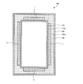
- FIG. 1 is a cross-sectional view showing a schematic configuration of a vacuum heat insulating material according to Embodiment 1 of the present invention.
- the vacuum heat insulating material 1 includes a core material 2, an adsorbent 3, a hydroxide 4, and an outer wrapping material 5 that covers these.
- the internal space of the outer packaging material 5 is sealed in a state of being decompressed to a degree of vacuum of about 1 Pa to 3 Pa.
- the vacuum heat insulating material 1 has a substantially rectangular and flat plate shape as a whole.
- the core material 2 is used for the purpose of holding a vacuum space.
- a fiber aggregate such as glass wool is used for the core material 2.
- the fiber assembly constituting the core material 2 may be one that has been subjected to heat and pressure molding, one that has been sealed and sealed using an inclusion material, or one that has been bonded with a binder.
- the adsorbent 3 adsorbs the gas or moisture inside the vacuum heat insulating material 1.
- the adsorbent 3 is used for the purpose of adsorbing gas or moisture inside the vacuum heat insulating material 1 to maintain the degree of vacuum inside the vacuum heat insulating material 1.
- calcium oxide (CaO) is used as the adsorbent 3.
- the adsorbent 3 may be silica gel or zeolite, or a combination thereof.
- the outer packaging material 5 is an outer packaging material 5 used for an existing vacuum heat insulating material, and is a laminated film having a multilayer structure.
- This multilayer structure has, for example, a structure in which a polyethylene layer, an aluminum-deposited ethylene-vinyl alcohol layer, an aluminum-deposited polyethylene terephthalate layer, and a nylon layer on the outermost layer are laminated in order from the core 2 side.
- the outer packaging material 5 is not limited to the said structure, It replaces with aluminum vapor deposition and alumina vapor deposition or silica vapor deposition may be used.
- the outer packaging material 5 should just have gas-barrier property.
- the hydroxide 4 holds the moisture released from the core material 2 by the heat treatment described later.
- the weight of the hydroxide 4 is at least 0.01 times the weight of the adsorbent 3 and the core material 2.
- calcium hydroxide (Ca (OH) 2 ) is used as the hydroxide 4.
- the hydroxide 4 may be magnesium hydroxide or aluminum hydroxide, or a combination thereof.
- FIG. 2 is a manufacturing process diagram of the vacuum heat insulating material according to the first embodiment of the present invention.
- the core material 2, the adsorbent 3 and the oxide are covered with the outer packaging material 5 and sealed (step S11) to form a sealed body.
- the oxide is, for example, calcium oxide.
- the sealed body is subjected to heat treatment (step S12).
- the condition of the heat treatment is, for example, 100 ° C. for 2 hours.
- the conditions for the heat treatment may be any conditions under which moisture is released from the core material 2.
- the hydroxide 4 is produced by the chemical reaction between the water released from the core material 2 and the oxide. That is, the water released from the core material 2 is held by the hydroxide 4.
- the hydroxide 4 produced is, for example, calcium hydroxide.
- step S13 a part of the outer packaging material 5 is opened.
- step S14 the inside of the outer packaging material 5 in a partially opened state is decompressed and sealed. That is, the inside of the outer packaging material 5 is depressurized to a vacuum degree of about 1 Pa to 3 Pa, and the unsealing portion is sealed by heat sealing or the like in the depressurized state.
- step S11 a step of adding the adsorbent 3 into the outer wrapping material 5 is further provided between step S13 and step S14.
- step S21 a step of adding the adsorbent 3 into the outer wrapping material 5
- FIG. 3 is a cross-sectional view showing a schematic configuration of a vacuum heat insulating material to which an adsorbent has been added in step S21 of the manufacturing process of FIG.
- the adsorbent 3 a when the adsorbent 3 a is added separately from the adsorbent 3, the adsorbent 3 a can be disposed in a region different from the region where the hydroxide 4 is disposed. If the adsorbent 3a to be added in this manner is disposed in a region different from the hydroxide 4, the bulkiness is prevented, and the outer wrapping material 5 can be prevented from being damaged from the inside.
- the adsorbent 3 corresponds to the first adsorbent of the present invention, and the adsorbent 3a corresponds to the second adsorbent of the present invention.
- the core material 2 is covered with the outer wrapping material 5 and then heat treatment is performed. Therefore, uniform drying of the core material 2 can be realized without depending on the relative humidity of the heat treatment furnace. Therefore, the amount of water released from the core material 2 does not fluctuate depending on the season and the weather after the reduced pressure sealing step inside the outer packaging material 5 in step S14. As a result, the variation in the degree of vacuum inside the outer packaging material 5 in each vacuum heat insulating material 1 is reduced, and the variation in the thermal conductivity of the vacuum heat insulating material 1, that is, the heat insulating performance is reduced.
- Example 1 In Example 1, the variation in the thermal conductivity of the vacuum heat insulating material 1 was examined.
- the samples and various conditions in Example 1 are as follows (1) to (5).
- Core material 2 Glass wool having a weight of 5 kg
- Outer packaging material 5 polyethylene layer, aluminum-deposited ethylene-vinyl alcohol layer, aluminum-deposited polyethylene terephthalate layer, and laminate having a multilayer structure in which a nylon layer is laminated on the outermost layer.
- Adsorbent 3 100 g of calcium oxide (4)
- Heat treatment 100 ° C. for 2 hours (5)
- Reduced pressure treatment Reduced pressure to a vacuum degree of about 1 Pa to 3 Pa
- Step S11 in FIG. 2 is a step of covering and sealing the core material 2, the adsorbent 3 and the oxide with the outer packaging material 5, but using calcium oxide of the above (3) as the adsorbent 3 Therefore, it is an oxide. Therefore, after all, in step S11, the core material 2 and the oxide of the above (3) are covered with the outer packaging material 5 and sealed. Moreover, the process of "adsorbent addition" of step S21 is not performed. And after measuring the heat conductivity of the vacuum heat insulating material 1, the vacuum heat insulating material 1 was opened and the weight of calcium hydroxide which is the hydroxide 4 was measured.
- Comparative Example 1 has the same samples and various conditions as the above (1) to (5) of Example 1. And after covering the core material 2 with the outer packaging material 5, the comparative example 1 performs said heat processing of (4) in the state which is not sealed. Next, the adsorbent 3 is disposed inside the outer wrapping material 5, and the inside of the outer wrapping material 5 is sealed.
- Table 1 shows the results of comparison of the average value of the thermal conductivity, the standard deviation, and the weight of calcium hydroxide of ten vacuum heat insulating materials 1 manufactured under the conditions of Example 1 and Comparative Example 1 respectively. It is.
- the average value of the thermal conductivity of the vacuum heat insulating material is 1.9 mW / (m ⁇ K), and the standard deviation is 0.3 mW / (m ⁇ K).
- the weight of calcium hydroxide was 0.8 g, which was 0.00016 times the weight of the core material.
- Example 1 the average value of the thermal conductivity of the vacuum heat insulating material 1 is 1.8 mW / (m ⁇ K), which is lower than that of Comparative Example 1. That is, the heat insulation performance of Example 1 is higher than that of Comparative Example 1.
- the standard deviation is 0.1 mW / (m ⁇ K), which is smaller than that of Comparative Example 1. That is, Example 1 has less variation in thermal conductivity than Comparative Example 1.
- Example 1 the weight of calcium hydroxide was 106.8 g, which was 0.021 times the weight of the core material.
- Example 2 The second embodiment has the same samples and various conditions as the above (1) to (5) of the first embodiment.
- the difference between the second embodiment and the first embodiment is that while the step of “addition of adsorbent” in step S21 is not performed in the first embodiment, the second embodiment is performed.
- 10 sheets of vacuum heat insulating material 1 were produced. After measuring the thermal conductivity of the vacuum heat insulating material 1, the vacuum heat insulating material 1 was opened and the weight of calcium hydroxide was measured.
- the sample used in Comparative Example 2 also has the same samples and various conditions as the above (1) to (5) of Example 1. And in the comparative example 2, the core material 2 and the adsorbent 3 were coat
- Table 2 shows the results of comparison of the average value of the thermal conductivity, the standard deviation, and the weight of calcium hydroxide of 10 vacuum heat insulating materials manufactured under the conditions of Example 1 and Comparative Example 1, respectively. is there.
- the average value of the vacuum heat insulating material was 1.8 mW / (m ⁇ K), and the standard deviation was 0.2 mW / (m ⁇ K).
- the weight of calcium hydroxide was 15.2 g, which was 0.0030 times the weight of the core material.
- Example 2 the average value of the thermal conductivity of the vacuum heat insulating material 1 is 1.7 mW / (m ⁇ K), which is lower than that of the comparative example. That is, the heat insulation performance of the second embodiment is higher than that of the second comparative example.
- the standard deviation is 0.1 mW / (m ⁇ K), which is smaller than that of Comparative Example 2. That is, Example 2 has less variation in thermal conductivity than Comparative Example 2.
- Example 2 the weight of calcium hydroxide was 120.4 g, which was 0.024 times the weight of the core material.
- Example 3 In Example 3, the above conditions (1), (2), (4) and (5) of Example 1 are the same. Then, using the adsorbent 3 as calcium oxide, the amount of calcium oxide was increased by 10 g from 10 g to 100 g, and ten pieces of vacuum heat insulating material 1 were produced in the manufacturing process shown in FIG. That is, ten vacuum heat insulating materials 1 are prepared with 10 g of calcium oxide adsorbent 3 and ten vacuum heat insulating materials 1 are prepared with 20 g calcium oxide adsorbent 3. In addition, the process of "adsorbent addition" of FIG.2 S21 is not performed.
- FIG. 4 is a view showing the relationship between the thermal conductivity and the weight ratio of calcium hydroxide to the core weight under the conditions of Example 3 in the vacuum heat insulating material according to Embodiment 1 of the present invention.
- the horizontal axis is the weight ratio [by] of calcium hydroxide to the core material weight
- the vertical axis is the thermal conductivity [mW / (m ⁇ K)].
- a group of plot points roughly arranged in the vertical direction in FIG. 4 is a plot point in the case of the same amount of calcium oxide, and is a plot point in the case of 10 g, 20 g,. ing.
- the vacuum heat insulating material in which the weight of calcium hydroxide is 0.01 times or more of the weight of the core material 2 has less variation in thermal conductivity and variation in heat insulating performance.
- the weight of calcium hydroxide is at least 0.01 times the weight of the core material 2 when the calcium oxide as the adsorbent 3 is 50 g or more.
- the amount of water held by the core 2 before heat treatment is at most 0.005 times the weight of the core.
- the mass per calcium hydroxide molecule is about four times the mass per water molecule. Therefore, if the weight of calcium hydroxide is at least 0.01 times the weight of the core material obtained by integrating “0.005” and “4”, almost all the water released from the core material 2 is hydroxylated It will be held by calcium. That is, the vacuum heat insulating material 1 in which the weight of calcium hydroxide is at least 0.01 times the weight of the core material 2 is the amount of water released from the core material 2 after sealing the inside of the outer packaging material 5 under reduced pressure.
- the amount of water released from the core material 2 does not change after sealing the inside of the outer packaging material 5 under reduced pressure, so that the variation of the degree of vacuum inside the outer packaging material 5 is small and the variation of the heat insulation performance is small. You can get one.
- the weight of calcium hydroxide is 0.021 times the weight of the core material 2, and in Example 2, it is 0.024 times and 0.01 times or more. It is contained in the range and the vacuum heat insulating material 1 with few dispersions of heat insulation performance is obtained.
- the lower limit value of the weight ratio of calcium hydroxide to the core material weight is 0.01 times or more as described above, but the upper limit value is 0.1 times.
- the reason why the upper limit value is set to 0.1 times is as follows. That is, when it is more than 0.1 times, the heat insulation performance is lowered, and the cost becomes high and can not be implemented industrially.
- FIG. 5 is a cross-sectional view showing a schematic configuration of a heat insulation box according to Embodiment 2 of the present invention.
- the heat insulation box 100 is used as, for example, a case of a refrigerator or the like which requires high heat insulation performance.
- the heat insulation box 100 has an inner case 110 and an outer case 120.
- the vacuum heat insulating material 1 described in the first embodiment is disposed, and heat insulation is performed between the inner box 110 and the outer box 120.
- the position where the vacuum heat insulating material 1 is disposed is, for example, a position in close contact with the outer wall surface 110 a of the inner box 110 or the like, and is disposed at a position where heat insulation can be performed between the inner box 110 and the outer box 120. And in the space between the inner case 110 and the outer case 120, the urethane foam heat insulating material 130 is filled in a portion other than the vacuum heat insulating material 1.
- the heat insulating box 100 is provided with the vacuum heat insulating material 1 with less variation in thermal conductivity. Thereby, the variation in the heat insulation performance of the heat insulation box 100 can be reduced. In a refrigerator or the like provided with the heat insulation box 100, the power consumption can be reduced.
- the vacuum heat insulating material 1 has high heat insulation performance compared with the urethane foam heat insulating material 130 grade
- the vacuum heat insulating material 1 has a higher thermal insulation than the urethane foam heat insulating material 130 and the like. In order to have performance, the foamed urethane heat insulating material 130 may be omitted.
- the vacuum heat insulating material 1 is in close contact with the outer wall surface 110 a of the inner box 110, but the vacuum heat insulating material 1 may be in close contact with the inner wall surface 120 a of the outer case 120.
- the vacuum heat insulating material 1 may be disposed in the space between the inner box 110 and the outer box 120 so as not to be in close contact with both the inner box 110 and the outer box 120 by using a spacer or the like.
- vacuum heat insulating material which concerns on this invention can be variously deformed not only in the above-mentioned embodiment, and it is possible to combine and implement each above-mentioned embodiment and modification.
- the vacuum heat insulating material 1 can also be used for a heat insulation box of a heat preservation container equipped with a heat source, a heat insulation box not equipped with a cold heat source and a heat source, such as a cooler box.
- the shape of the vacuum heat insulating material 1 is not limited to a predetermined non-deformable shape, but may be a deformable shape. As what used the vacuum heat insulating material 1 of a deformable shape, the heat insulation bag or the heat insulation container etc. which were equipped with the outer bag and the inner bag correspond, for example.
- Vacuum heat insulating material 1
- 2 cores 3 adsorbents, 4 hydroxides
- 5 outer packaging materials 100 heat insulation box, 110 inner box, 110a outer wall, 120 outer box, 120a inner wall, 130 urethane foam insulation.
Landscapes
- Engineering & Computer Science (AREA)
- General Engineering & Computer Science (AREA)
- Mechanical Engineering (AREA)
- Thermal Insulation (AREA)
- Refrigerator Housings (AREA)
Abstract
Priority Applications (5)
| Application Number | Priority Date | Filing Date | Title |
|---|---|---|---|
| CN201780091802.XA CN110892187B (zh) | 2017-07-25 | 2017-07-25 | 真空隔热件、隔热箱以及真空隔热件的制造方法 |
| PCT/JP2017/026778 WO2019021359A1 (fr) | 2017-07-25 | 2017-07-25 | Matériau d'isolation thermique sous vide, boîte d'isolation thermique, et procédé de fabrication dudit matériau d'isolation thermique sous vide |
| AU2017424996A AU2017424996B2 (en) | 2017-07-25 | 2017-07-25 | Vacuum insulation material, heat insulation box, and method for producing vacuum insulation material |
| JP2019532241A JP7129979B2 (ja) | 2017-07-25 | 2017-07-25 | 真空断熱材の製造方法 |
| TW107121299A TWI659177B (zh) | 2017-07-25 | 2018-06-21 | 真空絕熱材料、絕熱箱及真空絕熱材料之製造方法 |
Applications Claiming Priority (1)
| Application Number | Priority Date | Filing Date | Title |
|---|---|---|---|
| PCT/JP2017/026778 WO2019021359A1 (fr) | 2017-07-25 | 2017-07-25 | Matériau d'isolation thermique sous vide, boîte d'isolation thermique, et procédé de fabrication dudit matériau d'isolation thermique sous vide |
Publications (1)
| Publication Number | Publication Date |
|---|---|
| WO2019021359A1 true WO2019021359A1 (fr) | 2019-01-31 |
Family
ID=65040038
Family Applications (1)
| Application Number | Title | Priority Date | Filing Date |
|---|---|---|---|
| PCT/JP2017/026778 Ceased WO2019021359A1 (fr) | 2017-07-25 | 2017-07-25 | Matériau d'isolation thermique sous vide, boîte d'isolation thermique, et procédé de fabrication dudit matériau d'isolation thermique sous vide |
Country Status (5)
| Country | Link |
|---|---|
| JP (1) | JP7129979B2 (fr) |
| CN (1) | CN110892187B (fr) |
| AU (1) | AU2017424996B2 (fr) |
| TW (1) | TWI659177B (fr) |
| WO (1) | WO2019021359A1 (fr) |
Cited By (1)
| Publication number | Priority date | Publication date | Assignee | Title |
|---|---|---|---|---|
| JP7549786B2 (ja) | 2019-06-14 | 2024-09-12 | 三菱瓦斯化学株式会社 | 真空容器、その前駆体、および真空容器の製造方法 |
Citations (5)
| Publication number | Priority date | Publication date | Assignee | Title |
|---|---|---|---|---|
| JPH10318487A (ja) * | 1997-05-16 | 1998-12-04 | Mitsubishi Gas Chem Co Inc | 真空断熱材用ゲッタ |
| JPH11106539A (ja) * | 1997-10-03 | 1999-04-20 | Mitsubishi Gas Chem Co Inc | 真空断熱材用ゲッタおよびその製造法 |
| JP2015059642A (ja) * | 2013-09-20 | 2015-03-30 | パナソニック株式会社 | 真空断熱材及びそれを用いた冷蔵庫 |
| JP2015178853A (ja) * | 2014-03-19 | 2015-10-08 | 三菱電機株式会社 | 真空断熱材、断熱箱、及び真空断熱材の製造方法 |
| JP2016084833A (ja) * | 2014-10-23 | 2016-05-19 | 三菱電機株式会社 | 真空断熱材及び断熱箱 |
Family Cites Families (14)
| Publication number | Priority date | Publication date | Assignee | Title |
|---|---|---|---|---|
| JPS59225275A (ja) * | 1983-06-01 | 1984-12-18 | 松下電器産業株式会社 | 真空断熱材 |
| JPH09229290A (ja) * | 1996-02-28 | 1997-09-05 | Mitsubishi Chem Corp | 真空断熱材用複合材および真空断熱材の製造方法 |
| AU2002238861A1 (en) * | 2002-03-13 | 2003-09-22 | Matsushita Refrigeration Company | Refrigerator |
| JP3559035B2 (ja) * | 2002-12-05 | 2004-08-25 | 松下冷機株式会社 | 真空断熱材およびその製造方法、並びに真空断熱材を使用した防寒具およびパーソナルコンピューター |
| CN100537215C (zh) * | 2005-04-22 | 2009-09-09 | 海尔集团公司 | 一种宇航绝热板及其制备工艺 |
| JP2011241988A (ja) * | 2010-05-14 | 2011-12-01 | Hitachi Appliances Inc | 断熱箱体および冷蔵庫 |
| KR101323490B1 (ko) * | 2011-08-23 | 2013-10-31 | (주)엘지하우시스 | 수분 및 가스 흡착용 게터재를 구비한 진공 단열재 및 그 제조 방법 |
| KR101447767B1 (ko) * | 2011-12-02 | 2014-10-07 | (주)엘지하우시스 | 고온용 진공단열재 |
| JP6258029B2 (ja) * | 2012-12-26 | 2018-01-10 | 日本合成化学工業株式会社 | 真空断熱構造体用外装袋及びそれを用いた真空断熱構造体、並びに真空断熱構造体用外装袋の保管または輸送方法、及び真空断熱構造体用外装袋の製法 |
| JP6070213B2 (ja) * | 2013-01-24 | 2017-02-01 | Kyb株式会社 | 流体圧シリンダの配管固定具及びその製造方法 |
| EP2990712B1 (fr) * | 2013-04-23 | 2019-03-27 | Panasonic Intellectual Property Management Co., Ltd. | Isolant comprenant un adsorbant de gaz |
| JP6132715B2 (ja) * | 2013-09-06 | 2017-05-24 | 三菱電機株式会社 | 真空断熱材の製造方法及び断熱箱 |
| CN104712883A (zh) * | 2013-12-13 | 2015-06-17 | 陈照峰 | 一种秸秆为芯材的真空绝热板 |
| WO2017029727A1 (fr) * | 2015-08-19 | 2017-02-23 | 三菱電機株式会社 | Matériau d'isolation thermique sous vide et boîte d'isolation thermique |
-
2017
- 2017-07-25 WO PCT/JP2017/026778 patent/WO2019021359A1/fr not_active Ceased
- 2017-07-25 AU AU2017424996A patent/AU2017424996B2/en not_active Ceased
- 2017-07-25 JP JP2019532241A patent/JP7129979B2/ja active Active
- 2017-07-25 CN CN201780091802.XA patent/CN110892187B/zh not_active Expired - Fee Related
-
2018
- 2018-06-21 TW TW107121299A patent/TWI659177B/zh not_active IP Right Cessation
Patent Citations (5)
| Publication number | Priority date | Publication date | Assignee | Title |
|---|---|---|---|---|
| JPH10318487A (ja) * | 1997-05-16 | 1998-12-04 | Mitsubishi Gas Chem Co Inc | 真空断熱材用ゲッタ |
| JPH11106539A (ja) * | 1997-10-03 | 1999-04-20 | Mitsubishi Gas Chem Co Inc | 真空断熱材用ゲッタおよびその製造法 |
| JP2015059642A (ja) * | 2013-09-20 | 2015-03-30 | パナソニック株式会社 | 真空断熱材及びそれを用いた冷蔵庫 |
| JP2015178853A (ja) * | 2014-03-19 | 2015-10-08 | 三菱電機株式会社 | 真空断熱材、断熱箱、及び真空断熱材の製造方法 |
| JP2016084833A (ja) * | 2014-10-23 | 2016-05-19 | 三菱電機株式会社 | 真空断熱材及び断熱箱 |
Cited By (1)
| Publication number | Priority date | Publication date | Assignee | Title |
|---|---|---|---|---|
| JP7549786B2 (ja) | 2019-06-14 | 2024-09-12 | 三菱瓦斯化学株式会社 | 真空容器、その前駆体、および真空容器の製造方法 |
Also Published As
| Publication number | Publication date |
|---|---|
| AU2017424996A1 (en) | 2019-12-19 |
| CN110892187B (zh) | 2021-08-27 |
| JP7129979B2 (ja) | 2022-09-02 |
| JPWO2019021359A1 (ja) | 2020-02-06 |
| CN110892187A (zh) | 2020-03-17 |
| AU2017424996B2 (en) | 2021-03-11 |
| TWI659177B (zh) | 2019-05-11 |
| TW201908640A (zh) | 2019-03-01 |
Similar Documents
| Publication | Publication Date | Title |
|---|---|---|
| US9726438B2 (en) | Production of thermal insulation products | |
| CN204114473U (zh) | 真空隔热材料以及隔热箱 | |
| KR101560125B1 (ko) | 단열 성능이 향상된 단열 박스의 제조방법 및 이를 통해 제조된 단열 박스 | |
| CN103210250A (zh) | 真空绝热材料及其制备方法 | |
| JP2005106090A (ja) | 真空断熱パネル及びその製造方法 | |
| AU2018412205B2 (en) | Vacuum heat insulating material and heat insulating box | |
| CN106461148B (zh) | 密闭容器、隔热体和气体吸附器件 | |
| WO2019021359A1 (fr) | Matériau d'isolation thermique sous vide, boîte d'isolation thermique, et procédé de fabrication dudit matériau d'isolation thermique sous vide | |
| WO2015115149A1 (fr) | Matériau d'isolation thermique sous vide, boîte d'isolation thermique utilisant ledit matériau d'isolation thermique sous vide, et procédé de fabrication de matériau d'isolation thermique sous vide | |
| AU2015405840B2 (en) | Vacuum thermal insulator and thermal insulation container | |
| JP2016061435A (ja) | 真空断熱材、断熱箱、及び真空断熱材の製造方法 | |
| JP2001108187A (ja) | 真空断熱体,真空断熱体の製造方法及び保温容器 | |
| CN112092463A (zh) | 一种3d方形真空绝热板和保温容器 | |
| KR101452211B1 (ko) | 진공단열재용 심재 및 그를 이용한 진공단열재 | |
| CN108551761B (zh) | 真空隔热板的制备方法 | |
| RU2663675C2 (ru) | Вакуумированный теплоизоляционный материал, теплоизоляционная камера и способ изготовления вакуумированного теплоизоляционного материала | |
| KR20200086844A (ko) | 글라스 화이버 심재에 hgm을 함침한 진공단열패널 | |
| JP6778774B2 (ja) | 真空断熱パネルの製造方法 | |
| WO2024084774A1 (fr) | Matériau d'isolation thermique à vide | |
| HK1207146B (en) | Vacuum insulation material, insulated box, and method for producing vacuum insulation material | |
| JPS63279083A (ja) | 真空断熱材 | |
| JPS63279082A (ja) | 真空断熱材 | |
| JPS62141392A (ja) | 真空断熱材 |
Legal Events
| Date | Code | Title | Description |
|---|---|---|---|
| 121 | Ep: the epo has been informed by wipo that ep was designated in this application |
Ref document number: 17918989 Country of ref document: EP Kind code of ref document: A1 |
|
| ENP | Entry into the national phase |
Ref document number: 2019532241 Country of ref document: JP Kind code of ref document: A |
|
| ENP | Entry into the national phase |
Ref document number: 2017424996 Country of ref document: AU Date of ref document: 20170725 Kind code of ref document: A |
|
| NENP | Non-entry into the national phase |
Ref country code: DE |
|
| 122 | Ep: pct application non-entry in european phase |
Ref document number: 17918989 Country of ref document: EP Kind code of ref document: A1 |