WO2019021364A1 - Dispositif frigorifique et procédé de fonctionnement de dispositif frigorifique - Google Patents
Dispositif frigorifique et procédé de fonctionnement de dispositif frigorifique Download PDFInfo
- Publication number
- WO2019021364A1 WO2019021364A1 PCT/JP2017/026803 JP2017026803W WO2019021364A1 WO 2019021364 A1 WO2019021364 A1 WO 2019021364A1 JP 2017026803 W JP2017026803 W JP 2017026803W WO 2019021364 A1 WO2019021364 A1 WO 2019021364A1
- Authority
- WO
- WIPO (PCT)
- Prior art keywords
- refrigerant
- evaporator
- pressure
- refrigeration
- inlet
- Prior art date
- Legal status (The legal status is an assumption and is not a legal conclusion. Google has not performed a legal analysis and makes no representation as to the accuracy of the status listed.)
- Ceased
Links
Images

Classifications
-
- F—MECHANICAL ENGINEERING; LIGHTING; HEATING; WEAPONS; BLASTING
- F25—REFRIGERATION OR COOLING; COMBINED HEATING AND REFRIGERATION SYSTEMS; HEAT PUMP SYSTEMS; MANUFACTURE OR STORAGE OF ICE; LIQUEFACTION SOLIDIFICATION OF GASES
- F25B—REFRIGERATION MACHINES, PLANTS OR SYSTEMS; COMBINED HEATING AND REFRIGERATION SYSTEMS; HEAT PUMP SYSTEMS
- F25B1/00—Compression machines, plants or systems with non-reversible cycle
-
- F—MECHANICAL ENGINEERING; LIGHTING; HEATING; WEAPONS; BLASTING
- F25—REFRIGERATION OR COOLING; COMBINED HEATING AND REFRIGERATION SYSTEMS; HEAT PUMP SYSTEMS; MANUFACTURE OR STORAGE OF ICE; LIQUEFACTION SOLIDIFICATION OF GASES
- F25B—REFRIGERATION MACHINES, PLANTS OR SYSTEMS; COMBINED HEATING AND REFRIGERATION SYSTEMS; HEAT PUMP SYSTEMS
- F25B39/00—Evaporators; Condensers
- F25B39/02—Evaporators
Definitions
- the present invention relates to a refrigeration apparatus, and more particularly to a refrigeration apparatus that applies a non-azeotropic refrigerant mixture and a method of operating the refrigeration apparatus.
- a non-azeotropic mixed refrigerant obtained by mixing a plurality of types of refrigerants may be used as the refrigerant used in the refrigeration apparatus (see, for example, Patent Document 2).
- Counterflow can also be achieved for the evaporator of a refrigeration system using a non-azeotropic mixed refrigerant.
- the non-azeotropic mixed refrigerant changes its temperature by phase change under the same pressure. That is, since the non-azeotropic mixed refrigerant has a temperature gradient in the evaporation process, for example, in the case of an evaporator, the temperature is lower on the upstream side than on the downstream side in the evaporation process. Therefore, the temperature difference between the refrigerant and the heat source medium such as air or water can be further reduced, and the coefficient of performance (COP) is improved.
- COP coefficient of performance
- frost formation occurs in the evaporator at low temperature equipment whose saturation temperature is below freezing.
- the frost formation on the evaporator is biased. That is, cooling of air is promoted at the inlet side of the evaporator where the temperature of the non-azeotropic mixture refrigerant having a temperature gradient such that the temperature of the refrigerant changes due to phase change under the same pressure as described above is promoted and the amount of frost formation is At the outlet side of the evaporator where the temperature of the refrigerant is high, the cooling of the air does not proceed and the amount of frost formation decreases.
- the present invention relates to a refrigeration apparatus using a non-azeotropic mixture refrigerant having a temperature gradient, which prevents uneven frost, thereby preventing a decrease in COP of the refrigeration apparatus and a refrigeration capacity of the refrigeration apparatus.
- the purpose is to provide a driving method.
- the refrigeration apparatus includes a refrigeration cycle in which a compressor, a condenser, a pressure reducing device, and an evaporator are connected by a refrigerant pipe, and the refrigerant circulates inside, and the refrigerant is a mixture of plural types.
- the evaporator is a non-azeotropic mixture refrigerant, and the evaporator is characterized in that the pressure in the conduit in the evaporation process is reduced along the flow direction of the refrigerant in accordance with the temperature gradient of the non-azeotropic mixture refrigerant.
- the refrigerant temperature in the evaporator can be made substantially uniform, and the frost formation of the evaporator can be reduced.
- An object of the present invention is to obtain a refrigeration system that suppresses and suppresses the decrease in COP and refrigeration capacity of the refrigeration system.
- FIG. 5 is a Mollier diagram of the non-azeotropic mixed refrigerant used in the refrigeration apparatus according to Embodiment 1 of the present invention. It is a control flowchart of the freezing apparatus concerning Embodiment 1 of this invention.
- FIG. 7 is a Mollier diagram of the non-azeotropic mixed refrigerant used in the refrigeration apparatus according to Embodiment 2 of the present invention. It is the schematic showing the structure of the evaporator of the freezing apparatus which concerns on Embodiment 2 of this invention.
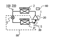
- FIG. 1 is a schematic diagram showing the entire configuration of a refrigeration apparatus 100 according to Embodiment 1 of the present invention.
- a compressor 1, a condenser 2, a pressure reducing device 3, and an evaporator 4 are sequentially connected by a refrigerant pipe 5.
- the refrigerating apparatus 100 includes a refrigerating cycle in which a refrigerant circulates in the order of the compressor 1, the condenser 2, the pressure reducing device 3, the evaporator 4, and the compressor 1.
- the control unit 60 controls each of the devices constituting the refrigeration system 100.
- the compressor 1 sucks in the refrigerant, compresses it, and discharges it in a high-temperature, high-pressure gas state.
- the compressor 1 may be configured, for example, by a compressor whose rotation number is controlled by an inverter circuit or the like and the discharge amount of the refrigerant can be adjusted by control of the rotation number.
- Condenser 2 In the condenser 2, the refrigerant compressed in the compressor 1 and brought into a high-temperature and high-pressure gas state flows in, and heat exchange is performed between the refrigerant and a heat source to cool the refrigerant to a low-temperature and high-pressure liquid state.
- the heat source include air, water, brine and the like.
- the heat source of the condenser 2 is outside air, which is outdoor air. The condenser 2 exchanges heat between the outside air and the refrigerant.
- the condenser blower 6 that blows the outside air to the condenser 2 when the refrigerant circulates in the refrigeration system 100 is provided.
- the condenser fan 6 may be configured to be capable of adjusting the air volume.
- the pressure reducing device 3 In the pressure reducing device 3, the low-temperature high-pressure liquid refrigerant cooled by the condenser 2 flows in, and the refrigerant is decompressed and expanded into a low-temperature low-pressure liquid state.
- the pressure reducing device 3 is composed of, for example, an electronic expansion valve, a refrigerant flow control means such as a temperature sensitive expansion valve, or a capillary tube.
- (Evaporator 4) In the evaporator 4, the low-temperature low-pressure liquid refrigerant expanded and decompressed by the pressure reducing device 3 flows in, heat is exchanged between the refrigerant and the cooling object, and the heat to be cooled is absorbed by the refrigerant to be cooled Cool down.
- the refrigerant evaporates into a high-temperature low-pressure gas state when the cooling target is cooled.
- the air to be cooled is indoor air. That is, the evaporator 4 exchanges heat between indoor air and the refrigerant.
- the evaporator blows indoor air to evaporator 4 while refrigerant is circulating in refrigeration apparatus 100.
- a blower 7 is provided.
- the evaporator fan 7 may be configured with an air volume adjustable.
- the specific structure of the evaporator 4 is demonstrated based on FIG.
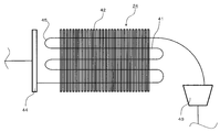
- the evaporator 4 is a plate-fin-tube heat exchanger composed of a plurality of heat transfer pipes 41, a plurality of fins 42, a refrigerant distributor 43, and a header 44.
- the number of the heat transfer tubes 41 is five and the number of the fins 42 is twenty eight in FIG. 2, the number and the number of these are only an example, and the present invention is not limited to this number and the number.
- FIG. 2 is a schematic diagram showing the configuration of the evaporator 4 of the refrigeration apparatus 100 according to Embodiment 1 of the present invention.
- FIG. 2 schematically shows the evaporator 4.
- the flow of the refrigerant in the evaporator 4 will be described with reference to FIG.
- the low-temperature low-pressure liquid refrigerant in the liquid state which has been reduced and expanded by the pressure reducing device 3 flows in from the inlet of the refrigerant distributor 43.
- the refrigerant that has flowed in from the inlet of the refrigerant distributor 43 is distributed into a plurality at the outlet of the refrigerant distributor 43, and flows from the respective outlets of the refrigerant distributor 43 to the heat transfer pipe 41.
- the refrigerant that has flowed into the heat transfer tube 41 flows along the axial direction of the heat transfer tube 41.
- the surfaces of the heat transfer tube 41 and the fins 42 are in contact with indoor air to be cooled which is blown by the blower 7 provided in the evaporator 4.
- Indoor air blown toward the fins 42 of the evaporator 4 flows in the opposite direction to the flow of the refrigerant flowing inside the evaporator 4.
- the refrigerant flowing inside the heat transfer tube 41 exchanges heat with indoor air in contact with the heat transfer tube 41 and the fins 42, and absorbs heat of the indoor air.
- the refrigerant heat-exchanged with indoor air in the heat transfer tube 41 flows in from the inlet of the header 44, joins at the header 44, and flows from the outlet of the header 44 to the compressor 1.
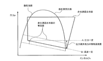
- FIG. 3 shows a Mollier diagram of the non-azeotropic mixed refrigerant used in the refrigeration apparatus 100 according to Embodiment 1 of the present invention.
- the non-azeotropic mixture refrigerant is a mixture of two or more refrigerants having different boiling points, and in the gas-liquid two-phase state, the pressure saturation temperature of the refrigerant changes according to the dryness even under a constant pressure. That is, when the refrigerant in the evaporator 4 is evaporated along the constant pressure line indicated by the dotted line A in FIG. 3, the temperature at the inlet of the evaporator 4 decreases and the temperature at the outlet increases. Therefore, as shown by the dotted line B in FIG.
- the temperature of the non-azeotropic refrigerant flowing to the evaporator 4 can be made uniform by continuously reducing the pressure inside the evaporator 4 with a predetermined gradient. . And by keeping the inlet temperature and the outlet temperature of the evaporator 4 uniform, it is possible to suppress the unevenness of the frost formed on the evaporator 4.
- the pressure inside the evaporator 4 As the pressure inside the evaporator 4 is gradually reduced, a pressure difference occurs between the inlet and the outlet of the evaporator 4.
- the relationship between the pressure of the refrigerant flowing inside the evaporator 4 and the saturation temperature is uniquely determined according to the composition of the refrigerant. Therefore, the pressure difference between the inlet and the outlet of the evaporator 4 when making the temperature uniform at the inlet and the outlet of the evaporator 4 is uniquely determined according to the composition of the refrigerant.
- the pressure difference of the refrigerant between the inlet and the outlet of the evaporator 4 is made equal to the temperature of the refrigerant flowing to the evaporator 4 and the refrigerant at the inlet and the outlet of the evaporator 4 By making the pressure difference the same, it is possible to suppress the frost formation of the evaporator 4.
- the heat transfer tube 41 constituting the evaporator 4 is usually a tube having a uniform inner diameter, but, for example, by gradually reducing the cross-sectional area of the heat transfer tube 41 from the inlet to the outlet of the evaporator 4, The pressure can be reduced. Alternatively, for example, the cross-sectional area of the heat transfer tube 41 may be gradually reduced from the inlet to the outlet of the evaporator 4.
- the resistance of the heat transfer tube 41 can be provided, and the pressure of the refrigerant flowing inside can be reduced by the resistance of the passage.
- the resistance of the heat transfer tube 41 can be provided, and the pressure of the refrigerant flowing inside can be reduced by the resistance of the passage.
- the heat transfer tube 41 can be lengthened to increase the pressure loss due to the pipeline resistance, and the pressure difference between the inlet and the outlet of the evaporator 4 can be increased.
- the above means may be appropriately selected according to the temperature gradient of the non-azeotropic mixed refrigerant to be applied.
- the pipe pressure loss in the evaporator 4 is substantially equal to the temperature gradient of the refrigerant, whereby the refrigerant temperature in the evaporator 4 is substantially equal. It can be made uniform. As a result, it is possible to prevent the performance deterioration of the refrigeration apparatus 100 due to frost formation on the inlet side of the evaporator 4 into which the refrigerant flows.
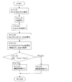
- FIG. 4 is a control flow diagram of the refrigeration apparatus 100 according to the first embodiment of the present invention.
- the refrigeration system 100 is used, for example, for a plurality of applications such as a unit cooler and a showcase.
- the broken line portion shown in FIG. 1 is a cooler 50, and the cooler 50 corresponds to a unit cooler or a showcase. Parts other than the broken line shown in FIG. 1 are so-called heat source machines.
- the control unit 60 controls the operation of the refrigeration system 100 by acquiring the pressure, temperature, and operating condition of each part of the heat source unit.
- Step i a refrigerant circulation amount Gr circulating in the inside of the refrigeration system 100 is calculated.
- the suction pressure Ps of the compressor 1 is detected by the pressure sensor 20 provided in the pipe on the suction side of the compressor 1.
- the suction temperature Th of the compressor 1 is detected by the temperature sensor 30 provided in the suction side piping of the compressor 1.
- the refrigerant circulation amount Gr is calculated by the following equation.
- Step ii the pressure loss ⁇ P between the inlet and outlet of the evaporator 4 is calculated from the refrigerant circulation amount Gr obtained in step i.
- ⁇ P is calculated by the following equation.
- ⁇ P ⁇ ⁇ f ⁇ (l / d) ⁇ ( ⁇ u 2 / 2g)
- l [m] pipe length
- d [m] pipe diameter
- ⁇ [kg / m 3 ] liquid density
- u [m / s] refrigerant flow rate
- f friction loss coefficient
- ⁇ correction coefficient Is.
- ⁇ , f, l, d and g are fixed values.
- the pressure loss ⁇ P increases as the refrigerant flow velocity u and the refrigerant density ⁇ ⁇ ⁇ increase.
- the refrigerant flow velocity u is obtained from the refrigerant circulation amount Gr.
- the pressure loss ⁇ P may be stored in advance in the control unit 60 as the value of ⁇ P obtained from the relationship between the refrigerant density ⁇ and the refrigerant circulation amount Gr.
- the relationship between the pressure loss ⁇ P, the refrigerant density ⁇ , and the refrigerant circulation amount Gr may be stored in advance in the control device as a look-up table. Step ii is called the pressure drop detection step of the evaporator 4.
- Step iii The inlet pressure Pein of the evaporator 4 is calculated.
- step i to step iii are collectively referred to as a detection step of detecting the pressure in the conduit at the inlet of the evaporator and at the outlet of the evaporator.
- Step iv The saturation temperature Tein at the inlet of the evaporator 4 is converted from Pein. Further, the saturation temperature Teout at the outlet of the evaporator 4 is converted from the suction pressure Ps. The conversion is obtained from the saturation pressure conversion table specific to the refrigerant type. Step iv is referred to as a temperature gradient detection step of determining a temperature gradient between the inlet of the evaporator 4 and the outlet of the evaporator 4.
- ⁇ Te Teout ⁇ Tein between the saturation temperature at the evaporator inlet and the saturation temperature at the evaporator outlet becomes zero
- the refrigerant circulation amount Gr is changed.
- Step v is called a flow rate changing step of changing the operating frequency F of the compressor 1 and changing the flow rate u of the refrigerant flowing through the refrigeration cycle.
- step iv and step v are collectively referred to as a pressure adjustment step.
- step v instead of changing the operating frequency F of the compressor 1, the opening degree of the flow control valve installed on the inlet side of the evaporator 4 is changed to change the flow velocity u of the refrigerant flowing through the refrigeration cycle Also good.
- the flow control valve may be the pressure reducing device 3. This control is performed when the controller 60 can control the cooler 50.
- the compressor 1, the condenser 2, the pressure reducing device 3, and the evaporator 4 are connected by the refrigerant pipe 5, and the refrigerant is circulated inside. Have a cycle.
- the refrigerant is a non-azeotropic mixed refrigerant obtained by mixing a plurality of types, and the evaporator 4 matches the temperature gradient of the isotherm of the gas-liquid two-phase region of the non-azeotropic mixed refrigerant, and the pressure in the pipe in the evaporation process is the refrigerant It is characterized by lowering along the flow direction of the With such a configuration, the refrigeration apparatus 100 can suppress the temperature difference between the refrigerant on the inlet side and the outlet side of the evaporator 4. Therefore, since the amount of frost formation is averaged on the inlet side and the outlet side of the evaporator 4, it is possible to prevent the heat exchange performance of the evaporator 4 from being deteriorated due to uneven frost formation.
- the cross-sectional area of the heat transfer tube 41 of the evaporator 4 decreases along the flow direction of the refrigerant.
- the heat transfer pipe 41 of the evaporator 4 is provided with the resistance means serving as the flow resistance of the refrigerant in the pipe line.
- the pressure in the conduit in the evaporation process is reduced by controlling the flow rate of the refrigerant passing through the evaporator 4.
- the refrigeration apparatus 100 can suppress the temperature difference between the inlet and the outlet of the evaporator 4 by flowing the non-azeotropic mixed refrigerant to the evaporator 4 at a predetermined flow rate. Further, the pressure loss applied to the refrigerant flowing in the evaporator 4 can be appropriately controlled according to the refrigerant used in the refrigeration apparatus 100 by combining the means of (2) to (4) as appropriate.
- the refrigerant is a non-azeotropic mixture refrigerant in which a plurality of types are mixed.
- the method further comprises the steps of detecting the pressure in the conduit at the outlet, and adjusting the pressure at the inlet and the outlet to match the difference in the pressure in the conduit with the temperature gradient of the refrigerant.
- the flow velocity is changed by changing the pressure in the conduit between the inlet and the outlet by changing the flow velocity of the refrigerant flowing through the evaporator 4 Have steps.
- the flow rate changing step changes the flow rate of the refrigerant flowing through the evaporator 4 by changing the rotational speed of the compressor 1.
- the flow rate changing step changes the opening degree of the flow rate adjustment valve installed at the inlet of the evaporator to change the flow rate of the refrigerant flowing through the heat transfer tube 41 Change the flow rate.
- the refrigeration apparatus 100 can change the flow rate of the refrigerant flowing through the evaporator 24 using the compressor 1 and the flow control valve that constitute the refrigeration cycle. Therefore, the pressure loss given to the refrigerant flowing in the evaporator 4 can be appropriately changed according to the physical properties of the non-azeotropic mixture refrigerant used in the refrigeration apparatus 100. Thereby, the freezing apparatus 100 can acquire the effect as described in said (1).
- the refrigeration apparatus 100 according to the second embodiment differs from the refrigeration apparatus 100 according to the first embodiment in that the composition of the refrigerant circulating in the refrigeration apparatus 100 is limited.
- the second embodiment will be described focusing on the changes from the first embodiment.
- the non-azeotropic mixed refrigerant circulating in the refrigerating apparatus 100 of the second embodiment is a mixed refrigerant of R32, R125, R134a, R1234yf, and carbon dioxide, and the ratio of R32 is 36 wt% of R32 , and the ratio of R125 X R125 is 30 wt%, the proportion X R134a is 14 wt% of R134a, ratio X R1234yf is 14 wt% of the R1234yf, the proportion X of co2 carbon dioxide is 6 wt%.
- each single refrigerant has physical properties that are advantages or disadvantages, but mixing a plurality of refrigerants can reduce the disadvantages and enhance the advantages.
- the physical properties of R32 the high operating pressure makes it possible to reduce the effect of pressure drop on performance degradation and improve the refrigeration capacity even at low temperatures such as in supermarket showcases.
- As a physical property of R1234yf since the global warming potential is 0, environmental impact can be reduced. Since the physical properties of R125 and R134a are noncombustible, it is possible to reduce the flammability which is the characteristic of R32 and R1234yf, and to enhance the safety.
- the non-azeotropic mixed refrigerant described above can reduce the influence on the global environment and simultaneously improve safety and performance.
- the mixed refrigerant is a non-azeotropic mixed refrigerant, and the temperature of the non-azeotropic mixed refrigerant changes due to a phase change under the same pressure, and the temperature on the downstream side becomes higher than that on the upstream side in the evaporation process. Therefore, when a non-azeotropic mixture refrigerant is used as the refrigerant of the refrigerator 100, the temperature at the inlet side of the evaporator 4 becomes lower than the outlet side of the evaporator 4.
- the mixed refrigerant containing R32 improves the refrigeration capacity even by using low temperatures, the refrigeration apparatus 100 is often used in low temperature devices such as showcases where the saturation temperature is below the freezing point. Therefore, frost formation occurs on the evaporator 4 when the mixed refrigerant containing R 32 is used in a low temperature apparatus whose saturation temperature is below the freezing point.
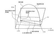
- FIG. 5 shows a Mollier diagram of the non-azeotropic mixed refrigerant used in the refrigeration apparatus 200 according to Embodiment 2 of the present invention.
- the non-azeotropic mixed refrigerant in the second embodiment when the non-azeotropic mixed refrigerant is phase-changed under a constant pressure in a low temperature range, as shown in FIG.
- the temperature gradient of the non-azeotropic mixed refrigerant at the inlet and the outlet of the evaporator 4 is ⁇ 5 ° C. That is, when the refrigerant flowing inside the evaporator 4 is heat-exchanged without causing pressure loss in the low temperature range, the temperature difference between the inlet and the outlet of the evaporator 4 is approximately 5 ° C.
- the temperature on the inlet side of the evaporator 4 is -12 ° C
- the temperature on the outlet side of the evaporator 4 is -7 ° C
- the temperature on the inlet side of the evaporator 4 is greatly reduced. Therefore, on the inlet side of the evaporator 4 where the temperature of the refrigerant is lower, the cooling of the air touching the heat transfer pipe 41 and the fins 42 is promoted, the water contained in the air is solidified, and it is easy to form frost. Is more than the outlet side of the evaporator 4. Therefore, the influence of the uneven frost on the refrigeration performance of the refrigeration apparatus 200 is also increased.
- the refrigerant saturation temperature difference between the inlet and the outlet of the evaporator 4 is calculated from the physical properties of the non-azeotropic mixture refrigerant. Then, in the refrigeration apparatus 200, the pressure difference between the inlet and the outlet of the evaporator 4 and the pressure difference between the inlet and the outlet of the evaporator 4 when making the temperature of the refrigerant flowing to the evaporator 4 uniform. In order to make it the same, piping pressure loss may be given to the refrigerant flowing through the evaporator 4.
- the refrigerant circulating in the refrigeration apparatus 200 has a composition of 36 wt% R32, 30 wt% R125, 14 wt% R134a, 14 wt% R1234yf and 6 wt% carbon dioxide.
- the refrigerant temperature in the evaporator 4 can be made substantially uniform.
- the refrigeration apparatus 200 can have less influence on the global environment and can simultaneously improve safety and refrigeration performance.
- each refrigerant constituting the non-azeotropic mixed refrigerant of the second embodiment may be a refrigerant having a different composition ratio of each refrigerant in a range of less than ⁇ 3 wt%. That is, the condition that the ratio of R32 X R32 (wt%) is 33 ⁇ X R32 ⁇ 39, the condition that the ratio X R125 X 25 (wt%) is 27 ⁇ X R125 ⁇ 33, the ratio X R134a X R134a ( wt%) satisfies 11 ⁇ X R134a ⁇ 17, R1234yf ratio X R1234yf (wt%) 11 ⁇ X R1234yf ⁇ 17 condition, carbon dioxide ratio X CO2 (wt%) 3 ⁇ X R125 Any refrigerant may be used as long as it satisfies ⁇ 9, and the total sum of X R32 , X R125 , X R134a , X R1234yf, and X
- the refrigerant circulating in the refrigeration apparatus 200 of the second embodiment may be any one of R448A, R449A, and R407F.
- R448A, R449A, and R407F are non-azeotropic mixture refrigerants, and in any case, the piping pressure loss imparted to the refrigerant in the evaporator 4 is configured to be substantially the same as the temperature gradient of the refrigerant, It is possible to make the temperature of the refrigerant in the evaporator 4 substantially uniform, and to prevent the heat exchange performance from deteriorating due to uneven frost distribution of the evaporator 4.
- the physical properties of the non-azeotropic mixed refrigerant according to the second embodiment are similar to the physical properties of R410A, and even if R410A is introduced into the refrigeration apparatus 200 according to the second embodiment, it can be operated without any problem.
- R410A is a pseudo-azeotropic mixture refrigerant, and is a refrigerant having almost no temperature gradient. That is, in FIG. 5, the isotherm of the refrigerant is almost horizontal, like the isotherm of the pseudo-azeotropic mixture refrigerant shown in the evaporator 4.
- the evaporator 4 needs to be configured to reduce the pressure loss of the heat transfer tube 41 in order to reduce the performance decrease when R410A is used.
- the refrigerant saturation temperature difference between the inlet and the outlet of the evaporator 4 in the low temperature range is approximately 5 ° C.
- Pressure loss to the refrigerant is approximately 5 ° C.
- the pressure loss in the evaporator 4 is made to be a temperature gradient of the non-azeotropic mixed refrigerant to be a pressure loss corresponding to less than 5 ° C.
- the heat transfer pipe 41 of the evaporator 4 is configured to reduce pressure loss with respect to the refrigerant flowing at a normal flow rate, and the refrigeration system 200 uses R410A.
- the refrigerant flows at a normal flow rate.
- the refrigerant flowing in the evaporator 4 flows so that the pressure loss becomes less than 5 ° C. as a temperature gradient of the non-azeotropic mixture refrigerant, and therefore, the refrigerant remains evaporated substantially at the same pressure as dotted line C shown in FIG. Flow out of the vessel 4.
- the refrigerant when the non-azeotropic mixed refrigerant according to the second embodiment is used, the refrigerant is flowed at a higher flow velocity than usual, and the heat transfer tube 41 is configured such that the pressure loss of the refrigerant in the pipe becomes large at the high flow velocity. Just do it.
- the pressure loss of the refrigerant in the evaporator 4 increases, and the pressure at the outlet becomes lower than the inlet of the evaporator 4 as indicated by a solid line D shown in FIG. There is no temperature difference between the inlet and the outlet of the refrigerant, and no uneven frost occurs.
- the refrigeration apparatus 200 can use both the non-azeotropic mixture refrigerant and the pseudo-azeotropic mixture refrigerant without reducing the refrigeration capacity.
- FIG. 6 is a schematic diagram showing the configuration of the evaporator 24 of the refrigeration apparatus 200 according to Embodiment 2 of the present invention.
- the heat transfer pipe 41 of the evaporator 24 according to the second embodiment is configured to give a predetermined pressure loss to the refrigerant flowing in the pipe.
- the freezing apparatus 200 is comprised so that the number of the flow paths of the refrigerant
- the refrigeration apparatus 200 switches the flow path of the refrigerant flowing through the evaporator 24, and the number of passes of the refrigerant is one as shown in FIG. , And is configured to pass through the evaporator 24.
- the heat transfer pipes 41 are connected by the U-shaped pipe 45 at the end of the evaporator 24, and the refrigerant flows back and forth at both ends of the evaporator 24 to make the flow path longer. . Since the refrigerant flow path is long, the pressure of the refrigerant passing through the evaporator 24 is reduced due to the pipe loss of the heat transfer pipe 41.
- the refrigeration apparatus 200 can use both the pseudo-azeotropic mixture refrigerant and the non-azeotropic mixture refrigerant without reducing the refrigeration capacity.
- the refrigerant is a mixed refrigerant of R32, R125, R134a, R1234yf, and carbon dioxide
- the ratio X32 of R32 is (wt%) , a condition which is 33wt% ⁇ X R32 ⁇ 39wt%
- the proportion X R125 in R125 (wt%) is a condition which is a 27wt% ⁇ X R125 ⁇ 33wt%
- the proportion of R134a X R134a (wt%) is 11 wt
- the ratio X CO2 (wt%) of carbon dioxide is 3 wt% ⁇ X CO2 ⁇ and conditions is 9wt%, X R32, X R125 ,
- the refrigerant is R448A, R449A, or R407F.
- the refrigerating cycle includes at least one of R32, R125, R134a, R1234yf, and a mixed refrigerant of carbon dioxide, R448A, R449A, and R407F.
- the refrigerant R410A can be shared. With such a configuration, the refrigeration apparatus 200 can be used, for example, in low-temperature equipment and various other applications.
- the pressure in the pipe line between the inlet and the outlet by changing the pipe length of the heat transfer pipe 41 of the evaporator 24 through which the refrigerant passes.
- the refrigeration apparatus 200 can provide pressure loss to the refrigerant passing through the evaporator 24 according to the refrigerant used. Therefore, since a plurality of types of refrigerant can be used for the refrigeration apparatus 200, the refrigeration apparatus 200 can be used for various applications.
- the pipe length changing step changes the number of passes of the refrigerant passing through the evaporator 24 and changes the pressure in the pipe between the inlet and the outlet. Change the difference between With such a configuration, the refrigeration apparatus 200 can change the pressure loss given to the refrigerant flowing in the evaporator 24 even in the evaporator 24 configured by the normal heat transfer tube 41. Further, by using the means described in the above (6) to (8) in combination, the width of the pressure loss given to the refrigerant flowing in the evaporator 24 is broadened, and the pressure difference between the refrigerant at the inlet and the outlet of the evaporator 24 It will also be possible to adjust properly.
Landscapes
- Engineering & Computer Science (AREA)
- Physics & Mathematics (AREA)
- Mechanical Engineering (AREA)
- Thermal Sciences (AREA)
- General Engineering & Computer Science (AREA)
- Compression-Type Refrigeration Machines With Reversible Cycles (AREA)
- Devices That Are Associated With Refrigeration Equipment (AREA)
- Defrosting Systems (AREA)
Abstract
La présente invention vise à empêcher la formation de givre non équilibrée dans un dispositif frigorifique à l'aide d'un mélange de réfrigérant non azéotrope ayant un gradient de température de façon à empêcher une baisse de COP et de puissance frigorifique pour le dispositif frigorifique. Ce dispositif frigorifique comprend un cycle frigorifique dans lequel un compresseur, un condenseur, un dispositif de réduction de pression et un évaporateur sont reliés à une tuyauterie de réfrigérant et dans lesquels circule un réfrigérant, et est caractérisé en ce que le réfrigérant soit un mélange de réfrigérants non azéotrope dans lequel une pluralité de types de réfrigérant sont mélangés et en ce que l'évaporateur réduise la pression interne de la tuyauterie en conformité avec la direction du flux de réfrigérant pendant un processus d'évaporation en fonction du gradient de température du mélange de réfrigérants non azéotrope.
Priority Applications (3)
| Application Number | Priority Date | Filing Date | Title |
|---|---|---|---|
| PCT/JP2017/026803 WO2019021364A1 (fr) | 2017-07-25 | 2017-07-25 | Dispositif frigorifique et procédé de fonctionnement de dispositif frigorifique |
| JP2019532244A JP6765538B2 (ja) | 2017-07-25 | 2017-07-25 | 冷凍装置及び冷凍装置の運転方法 |
| CN201780093104.3A CN110914608A (zh) | 2017-07-25 | 2017-07-25 | 制冷装置和制冷装置的运转方法 |
Applications Claiming Priority (1)
| Application Number | Priority Date | Filing Date | Title |
|---|---|---|---|
| PCT/JP2017/026803 WO2019021364A1 (fr) | 2017-07-25 | 2017-07-25 | Dispositif frigorifique et procédé de fonctionnement de dispositif frigorifique |
Publications (1)
| Publication Number | Publication Date |
|---|---|
| WO2019021364A1 true WO2019021364A1 (fr) | 2019-01-31 |
Family
ID=65041127
Family Applications (1)
| Application Number | Title | Priority Date | Filing Date |
|---|---|---|---|
| PCT/JP2017/026803 Ceased WO2019021364A1 (fr) | 2017-07-25 | 2017-07-25 | Dispositif frigorifique et procédé de fonctionnement de dispositif frigorifique |
Country Status (3)
| Country | Link |
|---|---|
| JP (1) | JP6765538B2 (fr) |
| CN (1) | CN110914608A (fr) |
| WO (1) | WO2019021364A1 (fr) |
Cited By (2)
| Publication number | Priority date | Publication date | Assignee | Title |
|---|---|---|---|---|
| JPWO2021070314A1 (fr) * | 2019-10-10 | 2021-04-15 | ||
| JP6958769B1 (ja) * | 2021-02-02 | 2021-11-02 | 三菱電機株式会社 | 冷凍サイクル装置 |
Citations (6)
| Publication number | Priority date | Publication date | Assignee | Title |
|---|---|---|---|---|
| JPH06272998A (ja) * | 1993-03-18 | 1994-09-27 | Toshiba Corp | 冷凍装置 |
| JPH08145490A (ja) * | 1994-11-17 | 1996-06-07 | Matsushita Refrig Co Ltd | ヒートポンプエアコン用熱交換器 |
| JPH09105560A (ja) * | 1995-08-04 | 1997-04-22 | Mitsubishi Electric Corp | 冷凍装置 |
| JPH09133433A (ja) * | 1995-11-07 | 1997-05-20 | Sanyo Electric Co Ltd | 熱交換器 |
| JP2007536390A (ja) * | 2004-04-29 | 2007-12-13 | ハネウェル・インターナショナル・インコーポレーテッド | テトラフルオロプロペン及び二酸化炭素を含んでなる組成物 |
| WO2017149642A1 (fr) * | 2016-03-01 | 2017-09-08 | 三菱電機株式会社 | Dispositif à cycle frigorifique |
Family Cites Families (3)
| Publication number | Priority date | Publication date | Assignee | Title |
|---|---|---|---|---|
| CN1253681C (zh) * | 2004-07-22 | 2006-04-26 | 春兰(集团)公司 | 热泵空调器的制冷剂流道布置方法及采用该方法的空调器 |
| EP2314966A4 (fr) * | 2008-06-10 | 2014-03-26 | Halla Visteon Climate Control | Systeme de climatisation pour vehicule a evaporateur du type a tubes et ailettes utilisant un refrigerant materiel hfo 1234yf |
| BR112012032795A2 (pt) * | 2010-06-22 | 2016-12-20 | Arkema Inc | composições de transferência de calor de hidroluorocarbonetos e uma hidrofluoroolefina |
-
2017
- 2017-07-25 WO PCT/JP2017/026803 patent/WO2019021364A1/fr not_active Ceased
- 2017-07-25 JP JP2019532244A patent/JP6765538B2/ja not_active Expired - Fee Related
- 2017-07-25 CN CN201780093104.3A patent/CN110914608A/zh active Pending
Patent Citations (6)
| Publication number | Priority date | Publication date | Assignee | Title |
|---|---|---|---|---|
| JPH06272998A (ja) * | 1993-03-18 | 1994-09-27 | Toshiba Corp | 冷凍装置 |
| JPH08145490A (ja) * | 1994-11-17 | 1996-06-07 | Matsushita Refrig Co Ltd | ヒートポンプエアコン用熱交換器 |
| JPH09105560A (ja) * | 1995-08-04 | 1997-04-22 | Mitsubishi Electric Corp | 冷凍装置 |
| JPH09133433A (ja) * | 1995-11-07 | 1997-05-20 | Sanyo Electric Co Ltd | 熱交換器 |
| JP2007536390A (ja) * | 2004-04-29 | 2007-12-13 | ハネウェル・インターナショナル・インコーポレーテッド | テトラフルオロプロペン及び二酸化炭素を含んでなる組成物 |
| WO2017149642A1 (fr) * | 2016-03-01 | 2017-09-08 | 三菱電機株式会社 | Dispositif à cycle frigorifique |
Cited By (6)
| Publication number | Priority date | Publication date | Assignee | Title |
|---|---|---|---|---|
| JPWO2021070314A1 (fr) * | 2019-10-10 | 2021-04-15 | ||
| WO2021070314A1 (fr) * | 2019-10-10 | 2021-04-15 | 三菱電機株式会社 | Dispositif à cycle frigorifique |
| JP7278399B2 (ja) | 2019-10-10 | 2023-05-19 | 三菱電機株式会社 | 冷凍サイクル装置 |
| JP6958769B1 (ja) * | 2021-02-02 | 2021-11-02 | 三菱電機株式会社 | 冷凍サイクル装置 |
| WO2022168153A1 (fr) * | 2021-02-02 | 2022-08-11 | 三菱電機株式会社 | Dispositif à cycle de réfrigération |
| US12398936B2 (en) | 2021-02-02 | 2025-08-26 | Mitsubishi Electric Corporation | Refrigeration cycle device |
Also Published As
| Publication number | Publication date |
|---|---|
| JP6765538B2 (ja) | 2020-10-07 |
| CN110914608A (zh) | 2020-03-24 |
| JPWO2019021364A1 (ja) | 2020-02-27 |
Similar Documents
| Publication | Publication Date | Title |
|---|---|---|
| GB2530915B (en) | Air-conditioning apparatus | |
| JP5423089B2 (ja) | 冷凍装置 | |
| KR100958399B1 (ko) | 보조냉각기를 이용한 hvac 장치 | |
| CN111542580A (zh) | 制冷循环装置 | |
| US9970693B2 (en) | Refrigeration cycle apparatus | |
| US20010037649A1 (en) | Air conditioner using flammable refrigerant | |
| JP6479181B2 (ja) | 空気調和装置 | |
| US11371760B2 (en) | Refrigeration cycle apparatus | |
| JPWO2015140883A1 (ja) | 空気調和機 | |
| JP6576603B1 (ja) | 空気調和装置 | |
| WO2019021464A1 (fr) | Dispositif de conditionnement d'air | |
| JP6765538B2 (ja) | 冷凍装置及び冷凍装置の運転方法 | |
| JP7112168B2 (ja) | 熱交換器及び冷凍サイクル装置 | |
| WO2020188756A1 (fr) | Climatiseur | |
| JP6715918B2 (ja) | 冷凍サイクル装置 | |
| JP2012237518A (ja) | 空気調和機 | |
| WO2018008129A1 (fr) | Dispositif à cycle de réfrigération | |
| US12398936B2 (en) | Refrigeration cycle device | |
| JP2008008593A (ja) | 冷凍装置 | |
| JP3298225B2 (ja) | 空気調和機 | |
| WO2018216187A1 (fr) | Dispositif à cycle frigorifique | |
| JP2019215155A (ja) | 冷凍サイクル装置 | |
| US20240401851A1 (en) | Refrigeration cycle apparatus | |
| JP2014129895A (ja) | 空気調和機 |
Legal Events
| Date | Code | Title | Description |
|---|---|---|---|
| 121 | Ep: the epo has been informed by wipo that ep was designated in this application |
Ref document number: 17918706 Country of ref document: EP Kind code of ref document: A1 |
|
| ENP | Entry into the national phase |
Ref document number: 2019532244 Country of ref document: JP Kind code of ref document: A |
|
| NENP | Non-entry into the national phase |
Ref country code: DE |
|
| 122 | Ep: pct application non-entry in european phase |
Ref document number: 17918706 Country of ref document: EP Kind code of ref document: A1 |