WO2019021399A1 - 換気装置 - Google Patents
換気装置 Download PDFInfo
- Publication number
- WO2019021399A1 WO2019021399A1 PCT/JP2017/027090 JP2017027090W WO2019021399A1 WO 2019021399 A1 WO2019021399 A1 WO 2019021399A1 JP 2017027090 W JP2017027090 W JP 2017027090W WO 2019021399 A1 WO2019021399 A1 WO 2019021399A1
- Authority
- WO
- WIPO (PCT)
- Prior art keywords
- area
- insulating sheet
- box
- control board
- electrical component
- Prior art date
- Legal status (The legal status is an assumption and is not a legal conclusion. Google has not performed a legal analysis and makes no representation as to the accuracy of the status listed.)
- Ceased
Links
Images








Classifications
-
- F—MECHANICAL ENGINEERING; LIGHTING; HEATING; WEAPONS; BLASTING
- F24—HEATING; RANGES; VENTILATING
- F24F—AIR-CONDITIONING; AIR-HUMIDIFICATION; VENTILATION; USE OF AIR CURRENTS FOR SCREENING
- F24F1/00—Room units for air-conditioning, e.g. separate or self-contained units or units receiving primary air from a central station
- F24F1/06—Separate outdoor units, e.g. outdoor unit to be linked to a separate room comprising a compressor and a heat exchanger
- F24F1/20—Electric components for separate outdoor units
- F24F1/22—Arrangement or mounting thereof
Definitions
- FIG. 1 Front view of a ventilation device according to a first embodiment of the present invention
- FIG. 1 An exploded perspective view of the ventilation device according to the first embodiment
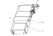
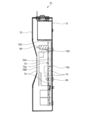
- the perspective view of the electrically equipped box in Embodiment 1 It is a perspective view of the electrically equipped box in Embodiment 1, Comprising: The figure which shows the state which removed the cover Sectional view of electrical component box in Embodiment 1
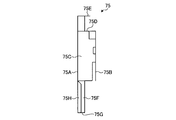
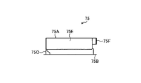
- the perspective view of the insulating sheet in Embodiment 1 Front view of insulating sheet in Embodiment 1 Left side view of insulating sheet in Embodiment 1 Right side view of the insulating sheet in Embodiment 1
- Rear view of insulating sheet in Embodiment 1 Sectional view of the electrical component box when the ventilating apparatus according to the first embodiment is installed vertically
- FIG. 1 is a front view of a ventilating apparatus according to a first embodiment of the present invention.
- FIG. 2 is an exploded perspective view of the ventilating apparatus according to the first embodiment.
- the ventilation device 1 is, for example, a wall mounted ventilation device attached to a wall of a room.
- the ventilation device 1 includes a front panel 10, a front casing 20, a back casing 30, an inner casing 40, blowers 50A and 50B, a heat exchanger 60, an electrical component box 70, and a terminal block box 80.
- the front panel 10, the front casing 20, and the back casing 30 constitute the main body of the ventilation device 1.
- the front panel 10 is detachably attached to the front side of the front casing 20.
- the front panel 10 is provided with an indoor air outlet 11 for discharging outdoor air from the main body on the front surface.
- the front panel 10 is provided with the indoor suction port 12 which inhales indoor air into the inside of a main body on the upper and lower surfaces.
- the back casing 30 is attached to the back side of the front casing 20.
- the back casing 30 includes an outdoor suction port 31 for sucking outdoor air into the inside of the main body, and an outdoor air outlet 32 for discharging indoor air from the inside of the main body.
- the blowers 50A and 50B are attached to the inner casing 40.
- the blower 50 ⁇ / b> A is disposed at a position facing the outdoor suction port 31, and generates an air supply flow flowing through the air supply ventilation passage 41.
- the blower 50 ⁇ / b> B is disposed at a position facing the exhaust opening 22, and generates an exhaust flow flowing through the exhaust ventilation path 42.
- the blower 50A has a motor 51A and an impeller 52A.
- the blower 50B has a motor 51B and an impeller 52B.
- the motors 51A and 51B are attached to a motor mounting plate 53.
- the motor mounting plate 53 is attached to the back casing 30 and the inner casing 40 so as to separate the exhaust flow and the charge air flow.
- FIG. 3 is a perspective view of the electrical component box 70 according to the first embodiment.
- FIG. 4 is a perspective view of the electrical equipment box 70 according to the first embodiment, showing a state in which the cover is removed.
- FIG. 5 is a cross-sectional view of electrical component box 70 according to the first embodiment.
- the insulating sheet 75 is provided between the case 71 and the second surface 73b of the control board 73 which is the back surface of the first surface 73a. It has a region 75A. The first region 75A covers the second surface 73b of the control substrate 73.
- the insulating sheet 75 has a second region 75 ⁇ / b> B covering the first surface 73 a of the control substrate 73.
- the area covered by the second area 75B is an area avoiding the connector 89.
- the insulating sheet 75 is formed by bending the end of the first area 75A toward the second area 75B, and ends of the third areas 75E, 75F, 75G, 75H, and the second area 75B. It has a third area 75D formed by bending toward the first area 75A.
- the third region 75D is located inside the connector 89.
- the third region 75E is located outside the control substrate 73.
- the insulating sheet 75 has the first area 75A, the second area 75B, the third areas 75D, 75E, 75F, 75G, 75H, and the fourth area 75C, so that the control substrate 73 and the electronic component 74 can be obtained. Dust accumulation is suppressed.
- the ventilator 1 is shown in a posture in which the longitudinal direction of the main body is aligned in the horizontal direction.
- This posture is simply referred to as horizontal installation.
- the electrical component box 70 is disposed in the posture shown in FIG. Most dusts deposited on the control substrate 73 and the electronic component 74 come from above.
- the upper side of the control board 73 and the electronic component 74 is covered by the third regions 75D and 75E. Therefore, dust falling from above in the interior of the electrical component box 70 is prevented from reaching the control board 73 and the electronic component 74 by the third regions 75D and 75E.
- the third regions 75D and 75E suppress the accumulation of dust on the control substrate 73 and the electronic component 74.
- FIG. 13 is a cross-sectional view of the electrical equipment box 70 when the ventilating apparatus 1 according to the first embodiment is installed vertically.
- the first surface 73a of the control substrate 73 and the upper side of the electronic component 74 are covered by the second region 75B. Therefore, dust falling from above in the interior of the electrical component box 70 is prevented from reaching the first surface 73 a of the control board 73 and the electronic component 74 by the second region 75 B.
- the second region 75B suppresses the accumulation of dust on the control substrate 73 and the electronic component 74.
- the region of the insulating sheet 75 is above the control board 73 and the electronic component 74 not only when the ventilation device 1 is installed horizontally or vertically, but also when installed in various postures. By being positioned, accumulation of dust on the control substrate 73 and the electronic component 74 can be suppressed.
- ventilating apparatus 1 when installation becomes possible by installing vertically, for example, when the wall to which ventilating apparatus 1 is attached is narrower than the width of the longitudinal direction of the main body because ventilating apparatus 1 can be installed in a plurality of postures. There is. In this way, the degree of freedom in architectural design can be improved by allowing the user to select the posture of the ventilator 1 according to the position of the ventilator 1 and the window and beam provided at the place where the ventilator 1 is attached. Do. Moreover, it becomes easy to aim at the improvement of the designability of the environment in which the ventilating apparatus 1 is installed by the option of an attitude
- the configuration shown in the above embodiment shows an example of the contents of the present invention, and can be combined with another known technique, and one of the configurations is possible within the scope of the present invention. Parts can be omitted or changed.
Landscapes
- Engineering & Computer Science (AREA)
- Chemical & Material Sciences (AREA)
- Combustion & Propulsion (AREA)
- Mechanical Engineering (AREA)
- General Engineering & Computer Science (AREA)
- Cooling Or The Like Of Electrical Apparatus (AREA)
- Casings For Electric Apparatus (AREA)
Abstract
本発明は、本体と、本体の内部に設けられた送風機と、本体の内部に設けられた電装ボックス(70)と、電装ボックス(70)の内部に固定された制御基板(73)と、制御基板(73)の第1面(73a)に搭載された電子部品(74)と、電装ボックス(70)の内部に設けられた絶縁シート(75)と、を備える。絶縁シート(75)は、第1面(73a)の裏面となる制御基板(73)の第2面(73b)と電装ボックス(70)との間に設けられる第1の領域(75A)と、第1面(73a)を覆う第2の領域(75B)と、を有する。
Description
本発明は、電装ボックスを有する換気装置に関する。
本体の内部に送風機が設けられた換気装置には、送風機を駆動するための電子部品が搭載された制御基板が設けられる。制御基板は、本体の内部に設けられた金属製の電装ボックスの内部に収納されている。特許文献1には、電装ボックスと制御基板との間の絶縁性を確保するために、ボックスと制御基板との間に絶縁シートを設けた構成が開示されている。
換気装置の電装ボックスは、ケースとカバーとで構成されており、ケースとカバーとの間には隙間が存在する。換気装置の本体の内部では、送風機が駆動することで空気の対流および圧力の変化が生じるため、ケースとカバーとの間から電装ボックスの内部に粉塵が侵入する場合がある。特に、粉塵の多い過酷環境下で換気装置が用いられた場合には、電装ボックスの内部に粉塵が侵入しやすくなる。
電装ボックスの内部に侵入した粉塵が、制御基板および制御基板に搭載された電子部品の上部に堆積すると、堆積した粉塵を介して電子部品間で短絡が発生し、換気装置が誤作動するおそれがある。特許文献1に開示された絶縁シートは、制御基板のうち電子部品が搭載されていない面を覆っているため、絶縁シートによって電子部品への粉塵の堆積を防ぐことはできない。
本発明は、上記に鑑みてなされたものであって、本体の内部に設けられた制御基板および制御基板に搭載された電子部品の上に粉塵が堆積しにくい換気装置を得ることを目的とする。
上述した課題を解決し、目的を達成するために、本発明は、本体と、本体の内部に設けられた送風機と、本体の内部に設けられた電装ボックスと、電装ボックスの内部に固定された制御基板と、制御基板の第1面に搭載された電子部品と、電装ボックスの内部に設けられた絶縁シートと、を備える。絶縁シートは、第1面の裏面となる制御基板の第2面と電装ボックスとの間に設けられる第1の領域と、第1面を覆う第2の領域と、を有する。
本発明にかかる換気装置は、本体の内部に設けられた制御基板および制御基板に搭載された電子部品の上に粉塵が堆積しにくいという効果を奏する。
以下に、本発明の実施の形態にかかる換気装置を図面に基づいて詳細に説明する。なお、この実施の形態によりこの発明が限定されるものではない。
実施の形態1.
図1は、本発明の実施の形態1にかかる換気装置の正面図である。図2は、実施の形態1にかかる換気装置の分解斜視図である。換気装置1は、例えば室内の壁に取り付けられる壁掛取付型の換気装置である。換気装置1は、フロントパネル10、フロントケーシング20、バックケーシング30、内部ケーシング40、送風機50A,50B、熱交換器60、電装ボックス70、端子台ボックス80を備えている。
図1は、本発明の実施の形態1にかかる換気装置の正面図である。図2は、実施の形態1にかかる換気装置の分解斜視図である。換気装置1は、例えば室内の壁に取り付けられる壁掛取付型の換気装置である。換気装置1は、フロントパネル10、フロントケーシング20、バックケーシング30、内部ケーシング40、送風機50A,50B、熱交換器60、電装ボックス70、端子台ボックス80を備えている。
フロントパネル10と、フロントケーシング20と、バックケーシング30とで、換気装置1の本体を構成する。フロントパネル10は、フロントケーシング20の前面側に着脱可能に取り付けられている。フロントパネル10は、室外空気を本体から吐き出す室内吹出口11を前面に備えている。フロントパネル10は、室内空気を本体の内部に吸い込む室内吸込口12を上面および下面に備えている。
フロントケーシング20は、室内吹出口11に通じる給気開口21と、室内吸込口12に通じる排気開口22とを備えている。
バックケーシング30は、フロントケーシング20の背面側に取り付けられている。バックケーシング30は、室外空気を本体の内部に吸い込む室外吸込口31と、室内空気を本体の内部から吐き出す室外吹出口32とを備えている。
内部ケーシング40は、フロントケーシング20とバックケーシング30との間に取り付けられている。内部ケーシング40は、室外吸込口31から給気開口21へと室外空気を流す給気通風路41と、排気開口22から室外吹出口32へと室内空気を流す排気通風路42とを備えている。
内部ケーシング40には、送風機50A,50Bが取り付けられている。送風機50Aは、室外吸込口31に対向する位置に配置されており、給気通風路41を流れる給気流を生成する。送風機50Bは、排気開口22に対向する位置に配置されており、排気通風路42を流れる排気流を生成する。送風機50Aは、モータ51Aおよび羽根車52Aを有する。送風機50Bは、モータ51Bおよび羽根車52Bを有している。モータ51A,51Bは、モータ取付板53に取り付けられている。モータ取付板53は、排気流と給気流とを隔てるようにバックケーシング30と内部ケーシング40に取り付けられている。
熱交換器60は、給気通風路41を流れる給気流と排気通風路42を流れる排気流との間で熱交換を行わせるものである。熱交換器60は、例えば直方体形状を有しており、対向面に向かう方向にのみ空気が流れる構造を有している。熱交換器60は、内部ケーシング40に保持されており、送風機50A,50B側に位置する2つの面において、一方の面からは給気流が流入し、他方の面からは排気流が流入する。熱交換器60の頂部および底部は内部ケーシング40と接触しているため、給気流と排気流とが互いに混ざり合うことが防がれる。
電装ボックス70は、フロントケーシング20とバックケーシング30との間に収められている。すなわち、電装ボックス70は本体の内部に設けられている。
図3は、実施の形態1における電装ボックス70の斜視図である。図4は、実施の形態1における電装ボックス70の斜視図であって、カバーを外した状態を示す図である。図5は、実施の形態1における電装ボックス70の断面図である。
電装ボックス70は、一面が開口71bとなっているケース71と、ケース71の開口71bを塞ぐカバー72とを有している。電装ボックス70の内部には、制御基板73が設けられている。制御基板73は、スペーサ88を介してケース71に固定されている。制御基板73の第1面73aには、複数の電子部品74が搭載されている。カバー72は、制御基板73の第1面73aおよび複数の電子部品74を覆う。制御基板73には、図示を省略したリードが接続可能なコネクタ89が設けられている。制御基板73は、リードを介してモータ51A,51Bと接続される。
電装ボックス70の内部には、絶縁材である絶縁シート75が設けられている。図6は、実施の形態1における絶縁シート75の斜視図である。図7は、実施の形態1における絶縁シート75の正面図である。図8は、実施の形態1における絶縁シート75の左側面図である。図9は、実施の形態1における絶縁シート75の右側面図である。図10は、実施の形態1における絶縁シート75の天面図である。図11は、実施の形態1における絶縁シート75の底面図である。図12は、実施の形態1における絶縁シート75の背面図である。
電子部品74の導電部は、人との接触を防ぐために強度のある構造体で覆われている必要がある。そのため、内部に制御基板73を収納する電装ボックス70は、金属製のケース71と金属製のカバー72とをネジ65で固定して構成され、電子部品74の導電部への外部からの接触を防いでいる。
また、金属製のケース71と、ケース71に固定された制御基板73との間では、絶縁性を確保する必要がある。ケース71と制御基板73との絶縁性を確保する手段には、両者の距離を広げるか、絶縁材を配置する手段がある。これらの手段のうち、両者の距離を広げることによる電装ボックス70の大型化を防ぐために、絶縁材を配置する手段が採用されることが多い。
本実施の形態1では、図5および図6に示すように、絶縁シート75は、第1面73aの裏面となる制御基板73の第2面73bとケース71との間に設けられる第1の領域75Aを有する。第1の領域75Aは、制御基板73の第2面73bを覆う。
また、絶縁シート75は、制御基板73の第1面73aを覆う第2の領域75Bを有する。なお、第2の領域75Bが覆う領域は、コネクタ89を避けた領域となっている。また、絶縁シート75は、第1の領域75Aの端部を第2の領域75B側に折り曲げて形成された第3の領域75E,75F,75G,75H、および第2の領域75Bの端部を第1の領域75A側に折り曲げて形成された第3の領域75Dを有する。第3の領域75Dは、コネクタ89の内側に位置する。第3の領域75Eは、制御基板73の外側に位置する。
また、絶縁シート75は、第1の領域75Aと第2の領域75Bとを連結する第4の領域75Cを有する。第2の領域75Bと第4の領域75Cとの連結部分には、ケース71の内壁に向けて突出するシート突起76が形成されている。図4に示すように、シート突起76は、ケース71の内壁に形成されたケース突起71aに当接する。シート突起76がケース突起71aに当接することで、電装ボックス70の内部での絶縁シート75の位置決めがなされる。これにより、例えばケース71の内壁と第4の領域75Cとの間のすき間を確保して、ここにリード線95を通しやすくなる。すなわち、電装ボックス70の内部で配線を引き回す際の作業性の向上を図ることができる。
なお、シート突起76が形成される位置は、第2の領域75Bと第4の領域75Cとの連結部分に限られない。シート突起76、絶縁シート75のいずれかの部分から突出して、電装ボックス70の内壁に当接していればよい。なお、本実施の形態1では、第4の領域75Cにコ字状の切込みを入れ、この切込みに囲まれた部分を立ち上げることでシート突起76にしている。
絶縁シート75が、第1の領域75A、第2の領域75B、第3の領域75D,75E,75F,75G,75H、第4の領域75Cを有することで、制御基板73および電子部品74への粉塵の堆積が抑制される。
例えば、図1に示す例では、換気装置1は本体の長手方向を水平方向に合わせた姿勢で示されている。なお、この姿勢を単に水平取付け設置と称する。換気装置1が水平取付け設置された状態では、電装ボックス70は、図5に示す姿勢で配置されている。制御基板73および電子部品74に堆積するほとんどの粉塵は、上方から舞い降りてきたものである。水平取付け設置された状態では、制御基板73および電子部品74の上方が第3の領域75D,75Eによって覆われる。したがって、電装ボックス70の内部で上方から落ちてくる粉塵は、制御基板73および電子部品74への到達が第3の領域75D,75Eによって防がれる。このように、換気装置1が水平取付け設置された状態では、第3の領域75D,75Eによって、制御基板73および電子部品74への粉塵の堆積が抑制される。
次に、換気装置1が本体の長手方向を鉛直方向に合わせた姿勢で配置された場合について説明する。なお、この姿勢を単に縦取付け設置と称する。図13は、実施の形態1にかかる換気装置1を縦取付け設置した場合の電装ボックス70の断面図である。この場合には、制御基板73の第1面73aおよび電子部品74の上方が、第2の領域75Bによって覆われる。したがって、電装ボックス70の内部で上方から落ちてくる粉塵は、制御基板73の第1面73aおよび電子部品74への到達が第2の領域75Bによって防がれる。このように、換気装置1が縦取付け設置された状態では、第2の領域75Bによって、制御基板73および電子部品74への粉塵の堆積が抑制される。
このように、本実施の形態1にかかる換気装置1では、姿勢を変えて設置した場合であっても、制御基板73および電子部品74への粉塵の堆積を抑制することができる。なお、換気装置1が水平取付け設置または縦取付け設置された場合に限らず、様々な姿勢で設置された場合にも、絶縁シート75の一部の領域が制御基板73および電子部品74の上方に位置するようにすることで、制御基板73および電子部品74への粉塵の堆積を抑制することができる。
なお、換気装置1が複数の姿勢で設置可能となることで、例えば換気装置1を取り付ける壁が本体の長手方向の幅よりも狭い場合には、縦取付け設置することで取付けが可能となる場合がある。このように、換気装置1を取り付ける場所、換気装置1を取り付ける場所に設けられた窓および梁の状態に応じて換気装置1の姿勢が選択可能となることで、建築設計的な自由度が向上する。また、姿勢の選択肢が広がることで、換気装置1が設置される環境の意匠性の向上を図りやすくなる。
以上の実施の形態に示した構成は、本発明の内容の一例を示すものであり、別の公知の技術と組み合わせることも可能であるし、本発明の要旨を逸脱しない範囲で、構成の一部を省略、変更することも可能である。
1 換気装置、10 フロントパネル、11 室内吹出口、12 室内吸込口、20 フロントケーシング、21 給気開口、22 排気開口、30 バックケーシング、31 室外吸込口、32 室外吹出口、40 内部ケーシング、41 給気通風路、42 排気通風路、50A,50B 送風機、51A,51B モータ、52A,52B 羽根車、53 モータ取付板、60 熱交換器、70 電装ボックス、71 ケース、71a ケース突起、71b 開口、72 カバー、73 制御基板、73a 第1面、73b 第2面、74 電子部品、75 絶縁シート、75A 第1の領域、75B 第2の領域、75C 第4の領域、75D,75E,75F,75G,75H 第3の領域、76 シート突起、80 端子台ボックス、88 スペーサ、89 コネクタ。
Claims (4)
- 本体と、
前記本体の内部に設けられた送風機と、
前記本体の内部に設けられた電装ボックスと、
前記電装ボックスの内部に固定された制御基板と、
前記制御基板の第1面に搭載された電子部品と、
前記電装ボックスの内部に設けられた絶縁シートと、を備え、
前記絶縁シートは、前記第1面の裏面となる前記制御基板の第2面と前記電装ボックスとの間に設けられる第1の領域と、前記第1面を覆う第2の領域と、を有することを特徴とする換気装置。 - 前記絶縁シートは、前記第1の領域と前記第2の領域の少なくとも一方の領域の端部が他方の領域側に折り曲げられて形成された第3の領域を有することを特徴とする請求項1に記載の換気装置。
- 前記絶縁シートは、前記電装ボックスの内壁に向けて突出して前記内壁に当接する突起を有することを特徴とする請求項1または請求項2に記載の換気装置。
- 前記絶縁シートは、前記第1の領域の端部と前記第2の領域の端部とをつなぐ第4の領域を有し、
前記突起は、前記第1の領域と前記第2の領域の少なくとも一方と前記第4の領域との連結部分に設けられていることを特徴とする請求項3に記載の換気装置。
Priority Applications (3)
| Application Number | Priority Date | Filing Date | Title |
|---|---|---|---|
| JP2019532274A JPWO2019021399A1 (ja) | 2017-07-26 | 2017-07-26 | 換気装置 |
| EP17918791.9A EP3661338B1 (en) | 2017-07-26 | 2017-07-26 | Ventilation device |
| PCT/JP2017/027090 WO2019021399A1 (ja) | 2017-07-26 | 2017-07-26 | 換気装置 |
Applications Claiming Priority (1)
| Application Number | Priority Date | Filing Date | Title |
|---|---|---|---|
| PCT/JP2017/027090 WO2019021399A1 (ja) | 2017-07-26 | 2017-07-26 | 換気装置 |
Publications (1)
| Publication Number | Publication Date |
|---|---|
| WO2019021399A1 true WO2019021399A1 (ja) | 2019-01-31 |
Family
ID=65040058
Family Applications (1)
| Application Number | Title | Priority Date | Filing Date |
|---|---|---|---|
| PCT/JP2017/027090 Ceased WO2019021399A1 (ja) | 2017-07-26 | 2017-07-26 | 換気装置 |
Country Status (3)
| Country | Link |
|---|---|
| EP (1) | EP3661338B1 (ja) |
| JP (1) | JPWO2019021399A1 (ja) |
| WO (1) | WO2019021399A1 (ja) |
Citations (5)
| Publication number | Priority date | Publication date | Assignee | Title |
|---|---|---|---|---|
| JPS5143079B2 (ja) | 1972-05-31 | 1976-11-19 | ||
| JPH07262468A (ja) * | 1994-03-18 | 1995-10-13 | Nohmi Bosai Ltd | 火災受信機 |
| JP2004214303A (ja) * | 2002-12-27 | 2004-07-29 | Hitachi Kokusai Electric Inc | 電子装置 |
| JP2009021315A (ja) * | 2007-07-11 | 2009-01-29 | Funai Electric Co Ltd | 電気機器の電源コード引出し部構造 |
| JP2014149106A (ja) * | 2013-01-31 | 2014-08-21 | Mitsubishi Electric Corp | 換気装置 |
Family Cites Families (5)
| Publication number | Priority date | Publication date | Assignee | Title |
|---|---|---|---|---|
| JPH07303584A (ja) * | 1994-05-16 | 1995-11-21 | Tec Corp | 電気機器 |
| JP3920839B2 (ja) * | 2003-10-24 | 2007-05-30 | 東芝キヤリア株式会社 | 空気調和機の室外ユニット |
| JP5663861B2 (ja) * | 2009-11-30 | 2015-02-04 | 株式会社オートネットワーク技術研究所 | 車載用の電気接続箱 |
| JP5995113B2 (ja) * | 2014-07-02 | 2016-09-21 | 株式会社オートネットワーク技術研究所 | 電気接続箱 |
| JP6620447B2 (ja) * | 2015-07-30 | 2019-12-18 | ブラザー工業株式会社 | 電子装置 |
-
2017
- 2017-07-26 WO PCT/JP2017/027090 patent/WO2019021399A1/ja not_active Ceased
- 2017-07-26 JP JP2019532274A patent/JPWO2019021399A1/ja active Pending
- 2017-07-26 EP EP17918791.9A patent/EP3661338B1/en active Active
Patent Citations (5)
| Publication number | Priority date | Publication date | Assignee | Title |
|---|---|---|---|---|
| JPS5143079B2 (ja) | 1972-05-31 | 1976-11-19 | ||
| JPH07262468A (ja) * | 1994-03-18 | 1995-10-13 | Nohmi Bosai Ltd | 火災受信機 |
| JP2004214303A (ja) * | 2002-12-27 | 2004-07-29 | Hitachi Kokusai Electric Inc | 電子装置 |
| JP2009021315A (ja) * | 2007-07-11 | 2009-01-29 | Funai Electric Co Ltd | 電気機器の電源コード引出し部構造 |
| JP2014149106A (ja) * | 2013-01-31 | 2014-08-21 | Mitsubishi Electric Corp | 換気装置 |
Non-Patent Citations (1)
| Title |
|---|
| See also references of EP3661338A4 |
Also Published As
| Publication number | Publication date |
|---|---|
| EP3661338A1 (en) | 2020-06-03 |
| EP3661338A4 (en) | 2020-08-12 |
| JPWO2019021399A1 (ja) | 2019-11-07 |
| EP3661338B1 (en) | 2025-02-12 |
Similar Documents
| Publication | Publication Date | Title |
|---|---|---|
| CN104976699B (zh) | 空调机的室外机 | |
| JP5966777B2 (ja) | 空気調和機の室外機 | |
| JP3985834B2 (ja) | 電装品アセンブリ、それを備えた空気調和装置の室外ユニット、及び空気調和装置 | |
| JPWO2018109932A1 (ja) | 空気調和機の室外機 | |
| JP2001244681A (ja) | ファンを有する電気装置 | |
| EP2551607A1 (en) | Ventilation apparatus | |
| JP2016120812A (ja) | 電力変換装置及びこれを備えた鉄道車両 | |
| CN102927624B (zh) | 空调机的室内机 | |
| JP2010164202A (ja) | 天井埋込形換気扇 | |
| JP7237160B2 (ja) | 熱交換型換気装置 | |
| JP2013064564A (ja) | 空気調和機 | |
| CN113646589A (zh) | 空调机的室外机 | |
| WO2019021399A1 (ja) | 換気装置 | |
| JP6594563B2 (ja) | 換気装置 | |
| JP2002185169A (ja) | 屋外設置型通信装置 | |
| JP2009097726A (ja) | 冷凍装置の室外ユニット | |
| JP6755404B2 (ja) | 空気調和機の室内機 | |
| CN100436952C (zh) | 空调机的室内机 | |
| JP2004170054A (ja) | 空気調和機 | |
| WO2023050758A1 (zh) | 空调用换热器密封板、室内机和空调 | |
| JP6053540B2 (ja) | 換気装置 | |
| JP5557110B2 (ja) | ダクト型空気調和機の室内機 | |
| JP3879712B2 (ja) | 空気調和装置 | |
| JP2010071518A (ja) | 空気調和装置の電装品ユニットならびに空気調和装置の室外機 | |
| CN122002724A (zh) | 电动马达驱动器和用于电动马达驱动器的外壳装置 |
Legal Events
| Date | Code | Title | Description |
|---|---|---|---|
| 121 | Ep: the epo has been informed by wipo that ep was designated in this application |
Ref document number: 17918791 Country of ref document: EP Kind code of ref document: A1 |
|
| ENP | Entry into the national phase |
Ref document number: 2019532274 Country of ref document: JP Kind code of ref document: A |
|
| NENP | Non-entry into the national phase |
Ref country code: DE |
|
| ENP | Entry into the national phase |
Ref document number: 2017918791 Country of ref document: EP Effective date: 20200226 |