WO2019021399A1 - Dispositif de ventilation - Google Patents
Dispositif de ventilation Download PDFInfo
- Publication number
- WO2019021399A1 WO2019021399A1 PCT/JP2017/027090 JP2017027090W WO2019021399A1 WO 2019021399 A1 WO2019021399 A1 WO 2019021399A1 JP 2017027090 W JP2017027090 W JP 2017027090W WO 2019021399 A1 WO2019021399 A1 WO 2019021399A1
- Authority
- WO
- WIPO (PCT)
- Prior art keywords
- area
- insulating sheet
- box
- control board
- electrical component
- Prior art date
- Legal status (The legal status is an assumption and is not a legal conclusion. Google has not performed a legal analysis and makes no representation as to the accuracy of the status listed.)
- Ceased
Links
Images






Classifications
-
- F—MECHANICAL ENGINEERING; LIGHTING; HEATING; WEAPONS; BLASTING
- F24—HEATING; RANGES; VENTILATING
- F24F—AIR-CONDITIONING; AIR-HUMIDIFICATION; VENTILATION; USE OF AIR CURRENTS FOR SCREENING
- F24F1/00—Room units for air-conditioning, e.g. separate or self-contained units or units receiving primary air from a central station
- F24F1/06—Separate outdoor units, e.g. outdoor unit to be linked to a separate room comprising a compressor and a heat exchanger
- F24F1/20—Electric components for separate outdoor units
- F24F1/22—Arrangement or mounting thereof
Definitions
- FIG. 1 Front view of a ventilation device according to a first embodiment of the present invention
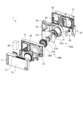
- FIG. 1 An exploded perspective view of the ventilation device according to the first embodiment
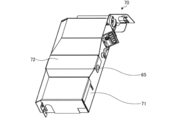
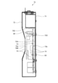
- the perspective view of the electrically equipped box in Embodiment 1 It is a perspective view of the electrically equipped box in Embodiment 1, Comprising: The figure which shows the state which removed the cover Sectional view of electrical component box in Embodiment 1
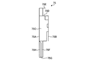
- the perspective view of the insulating sheet in Embodiment 1 Front view of insulating sheet in Embodiment 1 Left side view of insulating sheet in Embodiment 1 Right side view of the insulating sheet in Embodiment 1
- Rear view of insulating sheet in Embodiment 1 Sectional view of the electrical component box when the ventilating apparatus according to the first embodiment is installed vertically
- FIG. 1 is a front view of a ventilating apparatus according to a first embodiment of the present invention.
- FIG. 2 is an exploded perspective view of the ventilating apparatus according to the first embodiment.
- the ventilation device 1 is, for example, a wall mounted ventilation device attached to a wall of a room.
- the ventilation device 1 includes a front panel 10, a front casing 20, a back casing 30, an inner casing 40, blowers 50A and 50B, a heat exchanger 60, an electrical component box 70, and a terminal block box 80.
- the front panel 10, the front casing 20, and the back casing 30 constitute the main body of the ventilation device 1.
- the front panel 10 is detachably attached to the front side of the front casing 20.
- the front panel 10 is provided with an indoor air outlet 11 for discharging outdoor air from the main body on the front surface.
- the front panel 10 is provided with the indoor suction port 12 which inhales indoor air into the inside of a main body on the upper and lower surfaces.
- the back casing 30 is attached to the back side of the front casing 20.
- the back casing 30 includes an outdoor suction port 31 for sucking outdoor air into the inside of the main body, and an outdoor air outlet 32 for discharging indoor air from the inside of the main body.
- the blowers 50A and 50B are attached to the inner casing 40.
- the blower 50 ⁇ / b> A is disposed at a position facing the outdoor suction port 31, and generates an air supply flow flowing through the air supply ventilation passage 41.
- the blower 50 ⁇ / b> B is disposed at a position facing the exhaust opening 22, and generates an exhaust flow flowing through the exhaust ventilation path 42.
- the blower 50A has a motor 51A and an impeller 52A.
- the blower 50B has a motor 51B and an impeller 52B.
- the motors 51A and 51B are attached to a motor mounting plate 53.
- the motor mounting plate 53 is attached to the back casing 30 and the inner casing 40 so as to separate the exhaust flow and the charge air flow.
- FIG. 3 is a perspective view of the electrical component box 70 according to the first embodiment.
- FIG. 4 is a perspective view of the electrical equipment box 70 according to the first embodiment, showing a state in which the cover is removed.
- FIG. 5 is a cross-sectional view of electrical component box 70 according to the first embodiment.
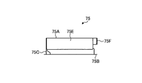
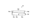
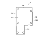
- the insulating sheet 75 is provided between the case 71 and the second surface 73b of the control board 73 which is the back surface of the first surface 73a. It has a region 75A. The first region 75A covers the second surface 73b of the control substrate 73.
- the insulating sheet 75 has a second region 75 ⁇ / b> B covering the first surface 73 a of the control substrate 73.
- the area covered by the second area 75B is an area avoiding the connector 89.
- the insulating sheet 75 is formed by bending the end of the first area 75A toward the second area 75B, and ends of the third areas 75E, 75F, 75G, 75H, and the second area 75B. It has a third area 75D formed by bending toward the first area 75A.
- the third region 75D is located inside the connector 89.
- the third region 75E is located outside the control substrate 73.
- the insulating sheet 75 has the first area 75A, the second area 75B, the third areas 75D, 75E, 75F, 75G, 75H, and the fourth area 75C, so that the control substrate 73 and the electronic component 74 can be obtained. Dust accumulation is suppressed.
- the ventilator 1 is shown in a posture in which the longitudinal direction of the main body is aligned in the horizontal direction.
- This posture is simply referred to as horizontal installation.
- the electrical component box 70 is disposed in the posture shown in FIG. Most dusts deposited on the control substrate 73 and the electronic component 74 come from above.
- the upper side of the control board 73 and the electronic component 74 is covered by the third regions 75D and 75E. Therefore, dust falling from above in the interior of the electrical component box 70 is prevented from reaching the control board 73 and the electronic component 74 by the third regions 75D and 75E.
- the third regions 75D and 75E suppress the accumulation of dust on the control substrate 73 and the electronic component 74.
- FIG. 13 is a cross-sectional view of the electrical equipment box 70 when the ventilating apparatus 1 according to the first embodiment is installed vertically.
- the first surface 73a of the control substrate 73 and the upper side of the electronic component 74 are covered by the second region 75B. Therefore, dust falling from above in the interior of the electrical component box 70 is prevented from reaching the first surface 73 a of the control board 73 and the electronic component 74 by the second region 75 B.
- the second region 75B suppresses the accumulation of dust on the control substrate 73 and the electronic component 74.
- the region of the insulating sheet 75 is above the control board 73 and the electronic component 74 not only when the ventilation device 1 is installed horizontally or vertically, but also when installed in various postures. By being positioned, accumulation of dust on the control substrate 73 and the electronic component 74 can be suppressed.
- ventilating apparatus 1 when installation becomes possible by installing vertically, for example, when the wall to which ventilating apparatus 1 is attached is narrower than the width of the longitudinal direction of the main body because ventilating apparatus 1 can be installed in a plurality of postures. There is. In this way, the degree of freedom in architectural design can be improved by allowing the user to select the posture of the ventilator 1 according to the position of the ventilator 1 and the window and beam provided at the place where the ventilator 1 is attached. Do. Moreover, it becomes easy to aim at the improvement of the designability of the environment in which the ventilating apparatus 1 is installed by the option of an attitude
- the configuration shown in the above embodiment shows an example of the contents of the present invention, and can be combined with another known technique, and one of the configurations is possible within the scope of the present invention. Parts can be omitted or changed.
Landscapes
- Engineering & Computer Science (AREA)
- Chemical & Material Sciences (AREA)
- Combustion & Propulsion (AREA)
- Mechanical Engineering (AREA)
- General Engineering & Computer Science (AREA)
- Cooling Or The Like Of Electrical Apparatus (AREA)
- Casings For Electric Apparatus (AREA)
Abstract
La présente invention comprend : un corps ; une soufflante disposée à l'intérieur du corps ; un boîtier électrique (70) disposé à l'intérieur du corps ; une carte de commande (73) fixée à l'intérieur du boîtier électrique (70) ; un composant électronique (74) chargé sur une première surface (73a) de la carte de commande (73) ; et une feuille d'isolation (75) disposée à l'intérieur du boîtier électrique (70). La feuille d'isolation (75) a une première zone (75A) disposée entre le boîtier électrique (70) et une seconde surface (73b) de la carte de commande (73), la seconde surface (73b) étant une surface arrière d'une première surface (73a) ; et une seconde zone (75B) qui recouvre la première surface (73a).
Priority Applications (3)
| Application Number | Priority Date | Filing Date | Title |
|---|---|---|---|
| JP2019532274A JPWO2019021399A1 (ja) | 2017-07-26 | 2017-07-26 | 換気装置 |
| EP17918791.9A EP3661338B1 (fr) | 2017-07-26 | 2017-07-26 | Dispositif de ventilation |
| PCT/JP2017/027090 WO2019021399A1 (fr) | 2017-07-26 | 2017-07-26 | Dispositif de ventilation |
Applications Claiming Priority (1)
| Application Number | Priority Date | Filing Date | Title |
|---|---|---|---|
| PCT/JP2017/027090 WO2019021399A1 (fr) | 2017-07-26 | 2017-07-26 | Dispositif de ventilation |
Publications (1)
| Publication Number | Publication Date |
|---|---|
| WO2019021399A1 true WO2019021399A1 (fr) | 2019-01-31 |
Family
ID=65040058
Family Applications (1)
| Application Number | Title | Priority Date | Filing Date |
|---|---|---|---|
| PCT/JP2017/027090 Ceased WO2019021399A1 (fr) | 2017-07-26 | 2017-07-26 | Dispositif de ventilation |
Country Status (3)
| Country | Link |
|---|---|
| EP (1) | EP3661338B1 (fr) |
| JP (1) | JPWO2019021399A1 (fr) |
| WO (1) | WO2019021399A1 (fr) |
Citations (5)
| Publication number | Priority date | Publication date | Assignee | Title |
|---|---|---|---|---|
| JPS5143079B2 (fr) | 1972-05-31 | 1976-11-19 | ||
| JPH07262468A (ja) * | 1994-03-18 | 1995-10-13 | Nohmi Bosai Ltd | 火災受信機 |
| JP2004214303A (ja) * | 2002-12-27 | 2004-07-29 | Hitachi Kokusai Electric Inc | 電子装置 |
| JP2009021315A (ja) * | 2007-07-11 | 2009-01-29 | Funai Electric Co Ltd | 電気機器の電源コード引出し部構造 |
| JP2014149106A (ja) * | 2013-01-31 | 2014-08-21 | Mitsubishi Electric Corp | 換気装置 |
Family Cites Families (5)
| Publication number | Priority date | Publication date | Assignee | Title |
|---|---|---|---|---|
| JPH07303584A (ja) * | 1994-05-16 | 1995-11-21 | Tec Corp | 電気機器 |
| JP3920839B2 (ja) * | 2003-10-24 | 2007-05-30 | 東芝キヤリア株式会社 | 空気調和機の室外ユニット |
| JP5663861B2 (ja) * | 2009-11-30 | 2015-02-04 | 株式会社オートネットワーク技術研究所 | 車載用の電気接続箱 |
| JP5995113B2 (ja) * | 2014-07-02 | 2016-09-21 | 株式会社オートネットワーク技術研究所 | 電気接続箱 |
| JP6620447B2 (ja) * | 2015-07-30 | 2019-12-18 | ブラザー工業株式会社 | 電子装置 |
-
2017
- 2017-07-26 WO PCT/JP2017/027090 patent/WO2019021399A1/fr not_active Ceased
- 2017-07-26 JP JP2019532274A patent/JPWO2019021399A1/ja active Pending
- 2017-07-26 EP EP17918791.9A patent/EP3661338B1/fr active Active
Patent Citations (5)
| Publication number | Priority date | Publication date | Assignee | Title |
|---|---|---|---|---|
| JPS5143079B2 (fr) | 1972-05-31 | 1976-11-19 | ||
| JPH07262468A (ja) * | 1994-03-18 | 1995-10-13 | Nohmi Bosai Ltd | 火災受信機 |
| JP2004214303A (ja) * | 2002-12-27 | 2004-07-29 | Hitachi Kokusai Electric Inc | 電子装置 |
| JP2009021315A (ja) * | 2007-07-11 | 2009-01-29 | Funai Electric Co Ltd | 電気機器の電源コード引出し部構造 |
| JP2014149106A (ja) * | 2013-01-31 | 2014-08-21 | Mitsubishi Electric Corp | 換気装置 |
Non-Patent Citations (1)
| Title |
|---|
| See also references of EP3661338A4 |
Also Published As
| Publication number | Publication date |
|---|---|
| JPWO2019021399A1 (ja) | 2019-11-07 |
| EP3661338A4 (fr) | 2020-08-12 |
| EP3661338B1 (fr) | 2025-02-12 |
| EP3661338A1 (fr) | 2020-06-03 |
Similar Documents
| Publication | Publication Date | Title |
|---|---|---|
| CN104976699B (zh) | 空调机的室外机 | |
| JP5966777B2 (ja) | 空気調和機の室外機 | |
| JP2007127378A (ja) | 電装品アセンブリ、それを備えた空気調和装置の室外ユニット、及び空気調和装置 | |
| CN110906460B (zh) | 空气调节机的室外机 | |
| JPWO2018109932A1 (ja) | 空気調和機の室外機 | |
| JP7237160B2 (ja) | 熱交換型換気装置 | |
| JP2001244681A (ja) | ファンを有する電気装置 | |
| EP2551607A1 (fr) | Appareil de ventilation | |
| CN102927624B (zh) | 空调机的室内机 | |
| JP2010164202A (ja) | 天井埋込形換気扇 | |
| JP2013064564A (ja) | 空気調和機 | |
| CN113646589A (zh) | 空调机的室外机 | |
| JP6594563B2 (ja) | 換気装置 | |
| EP3661338B1 (fr) | Dispositif de ventilation | |
| JP2002185169A (ja) | 屋外設置型通信装置 | |
| JP2009097726A (ja) | 冷凍装置の室外ユニット | |
| CN114731755B (zh) | 防静电构造和空调机 | |
| JP6755404B2 (ja) | 空気調和機の室内機 | |
| CN100436952C (zh) | 空调机的室内机 | |
| JP2004170054A (ja) | 空気調和機 | |
| WO2023050758A1 (fr) | Plaque d'étanchéité d'échangeur de chaleur pour climatiseur, unité d'intérieur et climatiseur | |
| CN203231494U (zh) | 安装面板以及侧出风、下出风及上出风式空调机室内机 | |
| JP6053540B2 (ja) | 換気装置 | |
| JP5557110B2 (ja) | ダクト型空気調和機の室内機 | |
| WO2021095130A1 (fr) | Dispositif de ventilation du type à échange de chaleur |
Legal Events
| Date | Code | Title | Description |
|---|---|---|---|
| 121 | Ep: the epo has been informed by wipo that ep was designated in this application |
Ref document number: 17918791 Country of ref document: EP Kind code of ref document: A1 |
|
| ENP | Entry into the national phase |
Ref document number: 2019532274 Country of ref document: JP Kind code of ref document: A |
|
| NENP | Non-entry into the national phase |
Ref country code: DE |
|
| ENP | Entry into the national phase |
Ref document number: 2017918791 Country of ref document: EP Effective date: 20200226 |