WO2019021425A1 - Mélangeur haute fréquence - Google Patents
Mélangeur haute fréquence Download PDFInfo
- Publication number
- WO2019021425A1 WO2019021425A1 PCT/JP2017/027272 JP2017027272W WO2019021425A1 WO 2019021425 A1 WO2019021425 A1 WO 2019021425A1 JP 2017027272 W JP2017027272 W JP 2017027272W WO 2019021425 A1 WO2019021425 A1 WO 2019021425A1
- Authority
- WO
- WIPO (PCT)
- Prior art keywords
- phase
- balanced
- wave
- signal
- mixed wave
- Prior art date
- Legal status (The legal status is an assumption and is not a legal conclusion. Google has not performed a legal analysis and makes no representation as to the accuracy of the status listed.)
- Ceased
Links
Images


Classifications
-
- H—ELECTRICITY
- H03—ELECTRONIC CIRCUITRY
- H03D—DEMODULATION OR TRANSFERENCE OF MODULATION FROM ONE CARRIER TO ANOTHER
- H03D7/00—Transference of modulation from one carrier to another, e.g. frequency-changing
- H03D7/14—Balanced arrangements
-
- H—ELECTRICITY
- H03—ELECTRONIC CIRCUITRY
- H03D—DEMODULATION OR TRANSFERENCE OF MODULATION FROM ONE CARRIER TO ANOTHER
- H03D7/00—Transference of modulation from one carrier to another, e.g. frequency-changing
- H03D7/14—Balanced arrangements
- H03D7/1425—Balanced arrangements with transistors
- H03D7/1458—Double balanced arrangements, i.e. where both input signals are differential
-
- H—ELECTRICITY
- H03—ELECTRONIC CIRCUITRY
- H03D—DEMODULATION OR TRANSFERENCE OF MODULATION FROM ONE CARRIER TO ANOTHER
- H03D7/00—Transference of modulation from one carrier to another, e.g. frequency-changing
- H03D7/14—Balanced arrangements
- H03D7/1425—Balanced arrangements with transistors
- H03D7/1475—Subharmonic mixer arrangements
-
- H—ELECTRICITY
- H03—ELECTRONIC CIRCUITRY
- H03D—DEMODULATION OR TRANSFERENCE OF MODULATION FROM ONE CARRIER TO ANOTHER
- H03D7/00—Transference of modulation from one carrier to another, e.g. frequency-changing
- H03D7/14—Balanced arrangements
- H03D7/1425—Balanced arrangements with transistors
- H03D7/1483—Balanced arrangements with transistors comprising components for selecting a particular frequency component of the output
-
- H—ELECTRICITY
- H03—ELECTRONIC CIRCUITRY
- H03D—DEMODULATION OR TRANSFERENCE OF MODULATION FROM ONE CARRIER TO ANOTHER
- H03D2200/00—Indexing scheme relating to details of demodulation or transference of modulation from one carrier to another covered by H03D
- H03D2200/0001—Circuit elements of demodulators
- H03D2200/0023—Balun circuits
Definitions
- the present invention relates to a high frequency mixer comprising an even harmonic mixer for mixing an intermediate frequency signal and a harmonic having a frequency twice that of the local signal.
- a high frequency mixer as a component used for a frequency converter of a microwave or millimeter wave band radio apparatus.
- an even harmonic mixer may be used which generates a mixed wave of a second harmonic which is a harmonic having a frequency twice the frequency of the LO wave and an IF signal which is an intermediate frequency signal.
- the high frequency mixer uses an even harmonic mixer, the frequency of the LO wave can be halved compared to the high frequency mixer which mixes the LO wave and the IF signal.
- the even harmonic mixer disclosed in Patent Document 1 below is one in which two unit mixers including three transistors shown below are arranged in parallel.
- the first NPN transistor whose collector terminal is connected to the power supply through the output load (2)
- the collector terminal is connected to the collector terminal of the first NPN transistor, and the emitter terminal is the emitter of the first NPN transistor
- a second NPN transistor (3) connected to the terminal, a collector terminal connected to the emitter terminals of the first and second NPN transistors, and a third NPN transistor connected to the ground terminal at the emitter terminal
- differential LO input terminals to which differential LO waves are input are connected to the base terminals of the first and second NPN transistors of each unit mixer, and differential IF signals are input
- the differential IF input terminal connected is connected to the base terminal of the third NPN transistor. Therefore, a mixed wave in which the second harmonic of the LO wave input from the differential LO input terminal and the IF signal input from the differential IF input terminal are mixed is the collector of the first and second NPN transistors. It is output from the terminal. Thus, the mixed wave is output from the output terminal connected to the collector terminals of the first and second NPN transistors.
- the mixed wave of the frequency 2 f LO + f IF from the output terminal connected to the collector terminals of the first and second NPN transistors A mixed wave having a frequency of 2f LO -f IF is output.
- the phase is reversed between the mixed wave whose frequency output from the output terminal of one unit mixer is 2f LO + f IF and the mixed wave whose frequency output from the output terminal of the other unit mixer is 2f LO -f IF ing. Therefore, the mixed wave of frequency 2f LO + f IF and the mixed wave of frequency 2 f LO -f IF are differential signals. Also, from the output terminal of one unit mixer, in addition to the mixed wave of frequency 2f LO + f IF , the double wave of the LO wave is output as a signal of frequency 2 f LO , and from the output terminal of the other unit mixer In addition to the mixed wave of frequency 2f LO -f IF , the second harmonic of LO wave is output. The second harmonic of the LO wave output from the output terminal of one unit mixer and the second harmonic of the LO wave output from the output terminal of the other unit mixer are in-phase signals.
- mixed waves of frequency 2f LO + f IF and mixed waves of frequency 2 f LO -f IF for example, when the mixed wave of frequency 2 f LO + f IF is a desired signal, the frequency is 2 f LO -f IF
- the mixed wave and the second harmonic of the LO wave are unwanted waves.
- a filter may be provided downstream of the even harmonic mixer, but the second harmonic of the LO wave is a desired signal. Since the frequency is close to the mixed wave of 2f LO + f IF at a certain frequency, a filter with a steep characteristic is required to remove the second harmonic of the LO wave.
- the present invention has been made to solve the above-described problems, and it is an object of the present invention to obtain a high frequency mixer capable of outputting a differential signal without incurring a passage loss associated with the removal of unnecessary waves.
- a high frequency mixer is a mixed wave of an intermediate frequency signal and a harmonic by mixing a differential intermediate frequency signal and a harmonic having a frequency twice that of the differential local signal.
- An even harmonic mixer that outputs a first mixed wave and outputs a second mixed wave that is a mixed wave of the first mixed wave and the reverse phase, and a first mixed wave output from the even harmonic mixer
- the first divided signal, which is divided into two, of the two divided signals of the first mixed wave, which is the divided signal in phase with the first mixed wave is output to the first output terminal, and the first mixed
- a first balanced and unbalanced circuit that outputs a second distributed signal that is a distributed signal of waves and reverse phase to the second output terminal, and a second mixed wave output from the even harmonic mixer into two Of the two distribution signals of the second mixing wave, the third distribution signal, which is the distribution signal in phase with the second mixing wave, And output to the output terminal, in which as and a second balun circuit outputting a fourth divided signal of a second mixed wave and the negative-phase
- the first mixed wave output from the even harmonic mixer is divided into two, and of the two divided signals of the first mixed wave, the divided signal in phase with the first mixed wave is used.
- a first balanced and unbalanced circuit that outputs a first distributed signal to a first output terminal and outputs a second distributed signal that is a distributed signal in reverse phase to the first mixed wave to a second output terminal
- the second mixed wave output from the even harmonic mixer is divided into two, and a third one of the two divided signals of the second mixed wave is a distributed signal in phase with the second mixed wave.
- FIG. 6 is an explanatory view showing a plurality of frequency components included in the output signal of the even harmonic mixer 3. It is a block diagram which shows the high frequency mixer by Embodiment 2 of this invention. It is a block diagram which shows the high frequency mixer by Embodiment 3 of this invention. It is a block diagram which shows the high frequency mixer by Embodiment 4 of this invention.
- FIG. 6 is an explanatory view showing an example of a first transformer 41 and a second transformer 44.
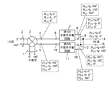
- FIG. 1 is a block diagram showing a high frequency mixer according to Embodiment 1 of the present invention.
- a differential IF terminal 1 is a terminal for inputting an IF signal with a phase of 0 ° and an IF signal with a phase of 180 ° as a differential IF signal (intermediate frequency signal).
- the differential LO terminal 2 is a terminal for inputting an LO wave having a phase of 0 ° and an LO wave having a phase of 180 ° as a differential LO wave (local signal).
- the even harmonic mixer 3 is a harmonic having a frequency that is twice the frequency of the differential IF signal input from the differential IF terminal 1 and the differential LO wave input from the differential LO terminal 2
- the second mixed wave is mixed, and a first mixed wave which is a mixed wave of an IF signal and a second harmonic of an LO wave is output from the positive phase output terminal 4, and the first mixed wave from the negative phase output terminal 5
- the positive phase output terminal 4 is a positive phase RF terminal of the even harmonic mixer 3 that outputs the first mixed wave.
- the negative phase output terminal 5 is a negative phase RF terminal of the even harmonic mixer 3 that outputs the second mixed wave.
- the first unbalanced terminal 6 is a terminal of the first balanced unbalanced circuit 7 connected to the positive phase output terminal 4 of the even harmonic mixer 3.
- the first balanced / unbalanced circuit 7 divides the first mixed wave output from the positive phase output terminal 4 of the even harmonic mixer 3 into two.
- the first balanced and unbalanced circuit 7 outputs, to the first output terminal 14, a first distributed signal that is a distributed signal in phase with the first mixed wave, of the two distributed signals of the first mixed wave.
- This is a circuit that outputs a second distribution signal, which is a distribution signal of the first mixed wave and the phase opposite to that of the first mixing wave, to the second output terminal 15.
- the first balanced positive phase terminal 8 is a terminal of the first balanced unbalanced circuit 7 connected to the first output terminal 14.
- the first balanced opposite phase terminal 9 is a terminal of the first balanced unbalanced circuit 7 connected to the second output terminal 15.
- the second unbalanced terminal 10 is a terminal of the second balanced and unbalanced circuit 11 connected to the negative phase output terminal 5 of the even harmonic mixer 3.
- the second balanced / unbalanced circuit 11 divides the second mixed wave output from the negative phase output terminal 5 of the even harmonic mixer 3 into two.
- the second balanced / unbalanced circuit 11 outputs, to the second output terminal 15, a third distributed signal of the two distributed signals of the second mixed wave, which is the distributed signal in phase with the second mixed wave. It is a circuit which outputs the 4th distribution signal which is a distribution signal of the 2nd mixed wave and reverse phase to the 1st output terminal 14.
- the second balanced positive phase terminal 12 is a terminal of the second balanced unbalanced circuit 11 connected to the second output terminal 15.
- the second balanced opposite phase terminal 13 is a terminal of the second balanced unbalanced circuit 11 connected to the first output terminal 14.
- the first output terminal 14 is connected to each of the first balanced positive phase terminal 8 of the first balanced unbalanced circuit 7 and the second balanced opposite phase terminal 13 of the second balanced unbalanced circuit 11. It is a positive phase output terminal.
- the second output terminal 15 is connected to each of the first balanced opposite phase terminal 9 of the first balanced unbalanced circuit 7 and the second balanced positive phase terminal 12 of the second balanced unbalanced circuit 11. It is a reverse phase output terminal.
- An IF signal with a phase of 0 ° and an IF signal with a phase of 180 ° are input from the differential IF terminal 1 as a differential IF signal, and a phase is 0 as a differential LO wave from the differential LO terminal 2
- An LO wave of °° and an LO wave of 180 ° in phase are input.
- the even harmonic mixer 3 mixes the differential IF signal input from the differential IF terminal 1 with the second harmonic of the differential LO wave input from the differential LO terminal 2.
- the even harmonic mixer 3 outputs a first mixed wave which is a mixed wave of an IF signal and a second harmonic of an LO wave from the positive phase output terminal 4, and outputs a first mixed wave from the negative phase output terminal 5.
- a second mixed wave which is a mixed wave of the opposite phase.
- the mixed wave of the frequency 2 f LO + f IF and the frequency 2 f LO- f IF And a mixed wave of the first and second mixed waves.
- a mixed wave having a frequency of 2f LO + f IF and a mixed wave having a frequency of 2 f LO ⁇ f IF are output from the negative phase output terminal 5 as a second mixed wave.
- the LO wave and the second harmonic of the LO wave leak from the positive phase output terminal 4 and the negative phase output terminal 5 of the even harmonic mixer 3 respectively.
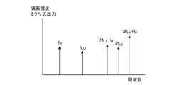
- FIG. 2 is an explanatory view showing a plurality of frequency components included in the output signal of the even harmonic mixer 3.
- the frequency f LO of the LO wave is a frequency separated from the frequency of the RF wave which is a high frequency signal as shown in FIG. 2, it can be easily cut off by a filter or the like.
- the frequency of the RF wave is a frequency such as 2f LO + f IF and 2f LO -f IF .
- the frequency 2f LO of the second harmonic of the LO wave is close to the frequency of the RF wave, it is necessary to use a filter with a steep characteristic when blocking using a filter.
- even a filter with a steep characteristic is used, it is difficult to eliminate, for example, the passing loss of the mixed wave having a frequency of 2f LO + f IF .
- phase relationship of the signals output from the positive phase output terminal 4 and the negative phase output terminal 5 of the even harmonic mixer 3 is as follows. Positive phase output terminal 4 Negative phase output terminal 5 2f LO + f IF 0 ° 180 ° 2f LO -f IF 0 ° 180 ° 2f LO 0 ° 0 °
- the first mixed wave output from the positive phase output terminal 4 of the even harmonic mixer 3 and the second mixed wave output from the negative phase output terminal 5 are in a reverse phase relationship.
- the second harmonic of the LO wave output from the positive phase output terminal 4 of the even harmonic mixer 3 and the second harmonic of the LO wave output from the negative phase output terminal 5 have an in-phase relationship.
- the phase of the first mixed wave is 0 ° and the phase of the second mixed wave is 180 °, but with the phase of the first mixed wave It is sufficient that the phase of the second mixed wave is in the opposite phase. Therefore, for example, an example may be considered in which the phase of the first mixed wave is 30 ° and the phase of the second mixed wave is 210 °.
- the first balanced / unbalanced circuit 7 divides the first mixed wave output from the positive phase output terminal 4 of the even harmonic mixer 3 into two.
- the first balanced and unbalanced circuit 7 is a first split signal that is a split signal in phase with the first mixing wave from the first balanced positive phase terminal 8 among the two split signals of the first mixing wave. Are output to the first output terminal 14. Further, the first balanced / unbalanced circuit 7 outputs, from the first balanced opposite phase terminal 9, a second divided signal which is a divided signal of the first mixed wave and the opposite phase to the second output terminal 15. .
- the second distribution signal is a signal obtained by shifting the phase of the distribution signal of one of the two distribution signals of the first mixing wave that is not the first distribution signal by 180 °, and the first distribution signal It is a distribution signal of reverse phase.
- the phase relationship of the signals output from the first balanced positive phase terminal 8 and the first balanced opposite phase terminal 9 of the first balanced unbalanced circuit 7 is as follows. First balanced positive phase terminal 8 First balanced negative phase terminal 9 2f LO + f IF 0 ° 180 ° 2f LO -f IF 0 ° 180 ° 2f LO 0 ° 180 °
- the second balanced / unbalanced circuit 11 divides the second mixed wave output from the negative phase output terminal 5 of the even harmonic mixer 3 into two.
- the second balanced / unbalanced circuit 11 is a third split signal that is a split signal in phase with the second mixed wave from the second balanced positive phase terminal 12 among the two split signals of the second mixed wave. Are output to the second output terminal 15. Further, the second balanced / unbalanced circuit 11 outputs, from the second balanced opposite phase terminal 13, a fourth divided signal, which is a distributed signal of the second mixed wave and the opposite phase, to the first output terminal 14. .
- the fourth distribution signal is a signal obtained by shifting the phase of the distribution signal other than the third distribution signal among the two distribution signals of the second mixing wave by 180 °, and is the third distribution signal It is a distribution signal of reverse phase.
- the phase relationship of the signals output from the second balanced positive phase terminal 12 and the second balanced negative phase terminal 13 of the second balanced unbalanced circuit 11 is as follows. Second balanced positive phase terminal 12 Second balanced negative phase terminal 13 2f LO + f IF 180 ° 0 ° 2f LO -f IF 180 ° 0 ° 2f LO 0 ° 180 °
- the signal of frequency 2f LO + f IF and the signal of frequency 2f LO -f IF outputted from the balanced reverse phase terminal 13 of the first phase are both in-phase signals of 0 ° in phase. Therefore, a signal of frequency 2f LO + f IF with a phase of 0 ° and a signal of frequency 2f LO -f IF with a phase of 0 ° are output from the first output terminal 14.
- a frequency 2f LO + f IF of the signal and the frequency 2f LO -f IF of the signal output from the first balanced anti-phase terminal 9 of the first balanced-unbalanced circuit 7, the second balun circuit 11 The signal of frequency 2f LO + f IF and the signal of frequency 2 f LO ⁇ f IF outputted from the second balanced positive phase terminal 12 are both in-phase signals of 180 ° in phase. Therefore, a signal of frequency 2f LO + f IF with a phase of 180 ° and a signal of frequency 2 f LO -f IF with a phase of 180 ° are output from the second output terminal 15. Therefore, the first output terminal 14 and the second output terminal 15 output differential signals that are a set of signals that are 180 ° out of phase with each other.
- the second harmonic of the frequency 2f LO is a signal with an opposite phase that is 180 ° out of phase. Therefore, the second harmonic frequency 2f LO output from the first balanced positive phase terminal 8 and the second harmonic frequency 2f LO output from the second balanced anti-phase terminal 13, a first output The terminal 14 is offset. Therefore, the second harmonic of the frequency 2f LO is not output from the first output terminal 14.
- the second harmonic of the frequency 2f LO is a signal with an opposite phase that is 180 ° out of phase. Therefore, the second harmonic of the frequency 2f LO output from the first balanced opposite phase terminal 9 and the second harmonic of the frequency 2f LO output from the second balanced positive phase terminal 12 have the second output.
- the terminal 15 is offset. Therefore, the second harmonic of the frequency 2f LO is not output from the second output terminal 15.
- the first mixed wave output from the even harmonic mixer 3 is divided into two, and of the two divided signals of the first mixed wave,
- a first distribution signal which is a distribution signal in phase with the first mixing wave, is output to the first output terminal 14, and a second distribution signal, which is a distribution signal in reverse phase to the first mixing wave, is output as a second distribution signal.
- the first balanced / unbalanced circuit 7 outputting to the output terminal 15 and the second mixed wave output from the even harmonic mixer 3 are divided into two, and of the two divided signals of the second mixed wave, A third distribution signal, which is a distribution signal in phase with the second mixing wave, is output to the second output terminal 15, and a fourth distribution signal, which is a distribution signal in reverse phase to the second mixing wave, is output as a first distribution signal. And a second balanced / unbalanced circuit 11 that outputs to the output terminal 14. As a result, the differential signal can be output without causing the passage loss associated with the removal of the unnecessary wave.
- the high frequency mixer includes the first balanced unbalance circuit 7 and the second balanced unbalance circuit 11 is shown.
- the first balanced unbalanced circuit 7 is a first merchant balun and the second balanced unbalanced circuit 11 is a second merchant balun.
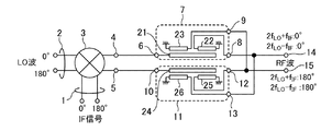
- FIG. 3 is a block diagram showing a high frequency mixer according to a second embodiment of the present invention.
- the first balanced and unbalanced circuit 7 which is a first merchant balun includes transmission lines 21, 22 and 23.
- the first balanced / unbalanced circuit 7, which is the first merchant balun divides the first mixed wave output from the even harmonic mixer 3 into two, and
- the first distribution signal which is the distribution signal in phase with the first mixing wave, of the two distribution signals of the mixing wave is outputted to the first output terminal 14, and the distribution signal of the phase opposite to the first mixing wave is output.
- a second distributed signal is output to the second output terminal 15.
- the transmission line 21 of the first merchant balun has one end connected to the first unbalanced terminal 6 and the other end opened, and the half wave length at the frequency 2f LO of the double wave.
- Is a line having The transmission line 22 of the first merchant balun has one end connected to the first balanced positive phase terminal 8 and the other end grounded, and is adjacently arranged parallel to the transmission line 21.
- the transmission line 22 is a line having a length of a quarter wavelength at a frequency 2f LO of a double wave.
- the transmission line 23 of the first merchant balun has one end connected to the first balanced opposite phase terminal 9 and the other end grounded, and is adjacently arranged in parallel with the transmission line 21. Further, the transmission line 23 is a line having a length of 1 ⁇ 4 wavelength at a frequency 2f LO of a double wave.
- the second balanced / unbalanced circuit 11, which is a second merchant balun, includes transmission lines 24, 25, 26.
- the second balanced / unbalanced circuit 11 which is the second merchant balun includes two second mixed waves output from the negative phase output terminal 5 of the even harmonic mixer 3. And, of the two distribution signals of the second mixing wave, the third distribution signal that is the distribution signal in phase with the second mixing wave is output to the second output terminal 15, and the second mixing wave A fourth distribution signal which is a distribution signal of reverse phase is output to the first output terminal 14.
- the transmission line 24 of the second merchant balun has one end connected to the second unbalanced terminal 10 and the other end opened, and a half wavelength length at a frequency 2f LO of a double wave.
- the transmission line 25 of the second merchant balun has one end connected to the second balanced positive phase terminal 12 and the other end grounded, and is adjacently arranged parallel to the transmission line 24. Further, the transmission line 25 is a line having a length of a quarter wavelength at a frequency 2f LO of a double wave.
- the transmission line 26 of the second merchant balun has one end connected to the second balanced opposite phase terminal 13 and the other end grounded, and is adjacently arranged in parallel with the transmission line 24. Further, the transmission line 26 is a line having a length of a quarter wavelength at a frequency 2f LO of a double wave.
- the first Marchant balun is used as the first balanced unbalance circuit 7, and the second Marchant balun is used as the second balanced unbalance circuit 11.
- the first merchant balun and the second merchant balun are known as broadband balanced-to-unbalanced conversion circuits. Therefore, each of the first merchant balun and the second merchant balun can suppress unnecessary waves other than the second harmonic of the LO wave output from the even harmonic mixer 3. For example, it is also possible to suppress LO waves and third harmonics whose frequency is 3f LO .
- the differential signal can be output without causing the passage loss associated with the removal of the unnecessary wave, and the unnecessary wave other than the double wave can be suppressed. it can.
- FIG. 4 is a block diagram showing a high frequency mixer according to a third embodiment of the present invention.
- the same reference numerals as those in FIG. 1 denote the same or corresponding parts, and the description thereof will be omitted.
- the first balanced and unbalanced circuit 7 includes a first in-phase distributor 31, a first transmission line 32 and a second transmission line 33.
- the first in-phase distributor 31 is connected to the first unbalanced terminal 6 and distributes the first mixed wave output from the positive phase output terminal 4 of the even harmonic mixer 3 in phase.
- the first transmission line 32 has one end connected to the first in-phase distributor 31 and the other end connected to the first balanced positive-phase terminal 8, and is in-phase distributed by the first in-phase distributor 31. It is a line that propagates one first mixed wave.
- the second transmission line 33 has one end connected to the first in-phase distributor 31 and the other end connected to the first balanced opposite phase terminal 9, and is in-phase distributed by the first in-phase distributor 31. It is a line that propagates the other first mixed wave.
- the second transmission line 33 has a line length longer than that of the first transmission line 32 by the half wave length at the frequency 2f LO of the double wave.
- the second balanced / unbalanced circuit 11 includes a second in-phase distributor 34, a third transmission line 35, and a fourth transmission line 36.
- the second in-phase distributor 34 is connected to the second unbalanced terminal 10 and distributes in phase the second mixed wave output from the negative phase output terminal 5 of the even harmonic mixer 3.
- the third transmission line 35 has one end connected to the second in-phase distributor 34 and the other end connected to the second balanced positive phase terminal 12, and is in-phase distributed by the second in-phase distributor 34. It is a line that propagates one second mixed wave.
- the fourth transmission line 36 has one end connected to the second in-phase distributor 34 and the other end connected to the second balanced opposite phase terminal 13, and is in-phase distributed by the second in-phase distributor 34.
- the fourth transmission line 36 has a line length longer than that of the third transmission line 35 by a half wavelength at the frequency 2f LO of the double wave.
- the first transmission line 32 and the third transmission line 35 have the same length.
- the first in-phase splitter 31 of the first balanced / unbalanced circuit 7 splits in phase the first mixed wave output from the positive phase output terminal 4 of the even harmonic mixer 3 and splits the first mixed wave in phase
- the second mixed wave is output to the first transmission line 32, and the other first mixed wave subjected to the in-phase distribution is output to the second transmission line 33.
- the second transmission line 33 of the first balanced and unbalanced circuit 7 has a line length longer than that of the first transmission line 32 by a half wavelength at the frequency 2f LO of the second harmonic. . For this reason, the phase of the signal propagated through the second transmission line 33 and output from the first balanced opposite phase terminal 9 is propagated through the first transmission line 32 to form the first balanced positive phase terminal 8. It is 180 degrees behind the phase of the signal output from.
- the second in-phase splitter 34 of the second balanced / unbalanced circuit 11 splits in phase the second mixed wave output from the negative phase output terminal 5 of the even harmonic mixer 3 and splits the second mixed wave in phase
- the second mixed wave of the in-phase distribution is output to the fourth transmission line 36.
- the fourth transmission line 36 of the second balanced / unbalanced circuit 11 has a line length longer than that of the third transmission line 35 by a half wavelength at the frequency 2f LO of the second harmonic. . Therefore, the phase of the signal transmitted through the fourth transmission line 36 and output from the second balanced opposite phase terminal 13 is propagated through the third transmission line 35, and the second balanced positive phase terminal 12 is transmitted. It is 180 degrees behind the phase of the signal output from.
- the phase difference between the two first mixed waves output from the first in-phase distributor 31 is originally 0 °, but even if the phase difference between the two first mixed waves is deviated from 0 °,
- the phase difference with the signal can be 180 °.
- the phase difference between the two second mixed waves output from the second in-phase distributor 34 is originally 0 °, the phase difference between the two second mixed waves is deviated from 0 °.
- the signal output from the second balanced positive phase terminal 12 and the second balanced negative phase terminal 13 can be obtained.
- the phase difference with the output signal can be made 180 °.
- the differential signal can be output without causing the passage loss accompanying the removal of the unnecessary wave.
- the amount of suppression of the second harmonic of the LO wave depends on the phase accuracy of the first unbalance circuit 7 and the second unbalance circuit 11.
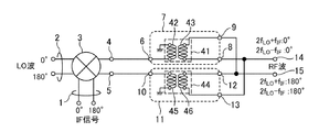
- FIG. 5 is a block diagram showing a high frequency mixer according to a fourth embodiment of the present invention.
- the same reference numerals as those in FIG. 5 are identical reference numerals as those in FIG. 5.
- the first balanced and unbalanced circuit 7 includes the first transformer 41
- the second balanced and unbalanced circuit 11 includes the second transformer 44.
- the first transformer 41 includes a first spiral line 42 and a second spiral line 43.
- the first spiral line 42 is a spiral line whose one end is connected to the first unbalanced terminal 6 and the other end is grounded.
- One end of the second spiral line 43 is connected to the first balanced positive phase terminal 8 and the other end is connected to the first balanced negative phase terminal 9, and the second spiral line 43 is connected to the first spiral line 42. It is a spiral-shaped line that induces electromagnetic induction.
- the second transformer 44 includes a third spiral line 45 and a fourth spiral line 46.
- the third spiral line 45 is a spiral line whose one end is connected to the second unbalanced terminal 10 and the other end is grounded.
- the fourth spiral line 46 has one end connected to the second balanced positive phase terminal 12 and the other end connected to the second balanced negative phase terminal 13, and the fourth spiral line 46 is connected to the third spiral line 45. It is a spiral-shaped line that induces electromagnetic induction.
- the first transformer 41 is formed by arranging the first spiral line 42 and the second spiral line 43, which are spiral-shaped lines, on the dielectric substrate. Be done.
- the second transformer 44 is also formed by arranging the third spiral line 45 and the fourth spiral line 46, which are spiral-shaped lines, on the dielectric substrate as shown in FIG.
- FIG. 6 is an explanatory view showing an example of the first transformer 41 and the second transformer 44. As shown in FIG. Although FIG. 6 shows an example in which the number of turns of each of the first transformer 41 and the second transformer 44 is one, increasing the number of turns strengthens the coupling of the two spiral lines, The size of the first transformer 41 and the second transformer 44 can be reduced.
- the first balanced unbalanced circuit 7 and the second balanced unbalanced circuit 11 include transmission lines, and at least a half wavelength of the second harmonic wave frequency 2f LO .
- the length is necessary. For this reason, it is necessary to secure at least an area for mounting a transmission line having a length of a half wavelength at frequency 2f LO .
- the first spiral line 42 and the second spiral line 43 in the first transformer 41 are spiral-shaped lines, and the third spiral line 45 in the second transformer 44 and the third spiral line 45
- the fourth spiral line 46 is a spiral line. Therefore, the mounting area can be made smaller than in the second and third embodiments. Further, in the fourth embodiment, as in the first embodiment, it is possible to output a differential signal without causing a passage loss accompanying the removal of the unnecessary wave.
- the present invention allows free combination of each embodiment, or modification of any component of each embodiment, or omission of any component in each embodiment. .
- the invention is suitable for high frequency mixers comprising even harmonic mixers that mix an intermediate frequency signal with harmonics having a frequency twice that of the local signal.
Landscapes
- Engineering & Computer Science (AREA)
- Power Engineering (AREA)
- Superheterodyne Receivers (AREA)
Abstract
La présente invention comprend : un premier circuit d'équilibrage et de déséquilibrage (7) qui divise, en deux, des premières ondes mélangées émises à partir d'un mélangeur d'harmoniques pairs (3), émet, à une première borne de sortie (14), un premier signal de division, c'est-à-dire le signal de division parmi les deux signaux de division des premières ondes mélangées qui est en phase avec les premières ondes mélangées, et émet, à une deuxième borne de sortie (15), un deuxième signal de division, c'est-à-dire le signal de division ayant la phase inverse aux premières ondes mélangées ; et un deuxième circuit d'équilibrage et de déséquilibrage (11) qui divise, en deux, des deuxièmes ondes mélangées émises par le mélangeur d'harmoniques pairs (3), émet, à la deuxième borne de sortie (15), un troisième signal de division, c'est-à-dire le signal de division parmi les deux signaux de division des deuxièmes ondes mélangées qui est en phase avec les deuxièmes ondes mélangées, et émet, à la première borne de sortie (14), un quatrième signal de division, c'est-à-dire le signal de division ayant la phase inverse aux deuxièmes ondes mélangées.
Priority Applications (4)
| Application Number | Priority Date | Filing Date | Title |
|---|---|---|---|
| PCT/JP2017/027272 WO2019021425A1 (fr) | 2017-07-27 | 2017-07-27 | Mélangeur haute fréquence |
| EP17918880.0A EP3648342A4 (fr) | 2017-07-27 | 2017-07-27 | Mélangeur haute fréquence |
| JP2018502190A JP6407473B1 (ja) | 2017-07-27 | 2017-07-27 | 高周波ミクサ |
| US16/621,579 US20200119692A1 (en) | 2017-07-27 | 2017-07-27 | Radio frequency mixer |
Applications Claiming Priority (1)
| Application Number | Priority Date | Filing Date | Title |
|---|---|---|---|
| PCT/JP2017/027272 WO2019021425A1 (fr) | 2017-07-27 | 2017-07-27 | Mélangeur haute fréquence |
Publications (1)
| Publication Number | Publication Date |
|---|---|
| WO2019021425A1 true WO2019021425A1 (fr) | 2019-01-31 |
Family
ID=63855274
Family Applications (1)
| Application Number | Title | Priority Date | Filing Date |
|---|---|---|---|
| PCT/JP2017/027272 Ceased WO2019021425A1 (fr) | 2017-07-27 | 2017-07-27 | Mélangeur haute fréquence |
Country Status (4)
| Country | Link |
|---|---|
| US (1) | US20200119692A1 (fr) |
| EP (1) | EP3648342A4 (fr) |
| JP (1) | JP6407473B1 (fr) |
| WO (1) | WO2019021425A1 (fr) |
Families Citing this family (3)
| Publication number | Priority date | Publication date | Assignee | Title |
|---|---|---|---|---|
| CN112671344B (zh) * | 2020-12-18 | 2022-10-11 | 电子科技大学 | 一种带压控电容匹配的基于变压器的自混频三倍频器 |
| SE544605C2 (en) * | 2021-01-21 | 2022-09-20 | Saab Ab | Compact balun with out-of-band spurious suppression |
| US11791860B2 (en) * | 2022-01-19 | 2023-10-17 | Swiftlink Technologies Inc. | Ultra compact and wide band folded Marchand Balun for millimeter-wave and beyond wireless communication |
Citations (6)
| Publication number | Priority date | Publication date | Assignee | Title |
|---|---|---|---|---|
| JPH10242765A (ja) * | 1997-02-25 | 1998-09-11 | Natl Space Dev Agency Japan<Nasda> | 周波数混合器及び送信機及び受信機及び送受信機システム |
| JPH10303650A (ja) * | 1997-04-23 | 1998-11-13 | Nippon Telegr & Teleph Corp <Ntt> | 周波数変換器 |
| JPH1117455A (ja) * | 1997-06-27 | 1999-01-22 | Sharp Corp | 周波数変換器 |
| WO2001001564A1 (fr) | 1999-06-29 | 2001-01-04 | Mitsubishi Denki Kabushiki Kaisha | Circuit a semiconducteur |
| JP2015100078A (ja) * | 2013-11-20 | 2015-05-28 | 三菱電機株式会社 | 周波数変換器 |
| JP2016178414A (ja) * | 2015-03-19 | 2016-10-06 | 三菱電機株式会社 | 高周波ミクサ |
Family Cites Families (3)
| Publication number | Priority date | Publication date | Assignee | Title |
|---|---|---|---|---|
| JP3023543B2 (ja) * | 1996-07-03 | 2000-03-21 | 関西酵素株式会社 | チロシナーゼ活性阻害剤及び化粧料 |
| JPH10247952A (ja) * | 1997-03-05 | 1998-09-14 | Fujitsu Ltd | 位相変調器 |
| JP5573308B2 (ja) * | 2010-04-01 | 2014-08-20 | 住友電気工業株式会社 | 電子回路 |
-
2017
- 2017-07-27 WO PCT/JP2017/027272 patent/WO2019021425A1/fr not_active Ceased
- 2017-07-27 JP JP2018502190A patent/JP6407473B1/ja not_active Expired - Fee Related
- 2017-07-27 US US16/621,579 patent/US20200119692A1/en not_active Abandoned
- 2017-07-27 EP EP17918880.0A patent/EP3648342A4/fr not_active Withdrawn
Patent Citations (6)
| Publication number | Priority date | Publication date | Assignee | Title |
|---|---|---|---|---|
| JPH10242765A (ja) * | 1997-02-25 | 1998-09-11 | Natl Space Dev Agency Japan<Nasda> | 周波数混合器及び送信機及び受信機及び送受信機システム |
| JPH10303650A (ja) * | 1997-04-23 | 1998-11-13 | Nippon Telegr & Teleph Corp <Ntt> | 周波数変換器 |
| JPH1117455A (ja) * | 1997-06-27 | 1999-01-22 | Sharp Corp | 周波数変換器 |
| WO2001001564A1 (fr) | 1999-06-29 | 2001-01-04 | Mitsubishi Denki Kabushiki Kaisha | Circuit a semiconducteur |
| JP2015100078A (ja) * | 2013-11-20 | 2015-05-28 | 三菱電機株式会社 | 周波数変換器 |
| JP2016178414A (ja) * | 2015-03-19 | 2016-10-06 | 三菱電機株式会社 | 高周波ミクサ |
Non-Patent Citations (1)
| Title |
|---|
| See also references of EP3648342A4 * |
Also Published As
| Publication number | Publication date |
|---|---|
| JP6407473B1 (ja) | 2018-10-17 |
| EP3648342A4 (fr) | 2020-07-15 |
| EP3648342A1 (fr) | 2020-05-06 |
| JPWO2019021425A1 (ja) | 2019-07-25 |
| US20200119692A1 (en) | 2020-04-16 |
Similar Documents
| Publication | Publication Date | Title |
|---|---|---|
| US9712313B2 (en) | Systems for multi-peak-filter-based analog self-interference cancellation | |
| WO2019021425A1 (fr) | Mélangeur haute fréquence | |
| US20100001781A1 (en) | Reconfigurable Heterodyne Mixer and Configuration Methods | |
| JPH1070481A (ja) | 中間周波数信号発生装置、周波数変換装置、送信装置、受信装置及び送、受信装置 | |
| US7042960B2 (en) | Low order spur cancellation mixer topologies | |
| JP5997596B2 (ja) | ミキサ | |
| JP4765029B2 (ja) | 映像周波数を強固に排除する低ノイズ周波数コンバータ | |
| JP2014116697A5 (fr) | ||
| JP2000216697A (ja) | 受信器またはスペクトラム・アナライザ―のための多重ヘテロダイン・ステ―ジ | |
| JP4501711B2 (ja) | 偶高調波ミクサ | |
| US11211969B2 (en) | Enhanced linearity mixer | |
| JP6299637B2 (ja) | 高周波ミクサ | |
| JP6625290B2 (ja) | 同相抑制回路 | |
| JP4849422B2 (ja) | イメージリジェクションミクサ及び無線装置 | |
| JP4185017B2 (ja) | 周波数変換回路 | |
| JP7287349B2 (ja) | レーダ回路ユニット、レーダ装置 | |
| US8600333B2 (en) | Apparatus for mixing frequency | |
| JP3343223B2 (ja) | イメージ抑圧ミクサ | |
| JPH0974316A (ja) | 周波数混合器 | |
| US20140004809A1 (en) | Frequency mixer | |
| JP2002009552A (ja) | 周波数逓倍器 | |
| JP2020010193A (ja) | 周波数変換器 | |
| CN116455332A (zh) | 行波混频器 | |
| JP2013243748A (ja) | 半導体装置及び無線通信機 | |
| JPWO2009063560A1 (ja) | 周波数変換装置及びこれを用いた送信機 |
Legal Events
| Date | Code | Title | Description |
|---|---|---|---|
| ENP | Entry into the national phase |
Ref document number: 2018502190 Country of ref document: JP Kind code of ref document: A |
|
| 121 | Ep: the epo has been informed by wipo that ep was designated in this application |
Ref document number: 17918880 Country of ref document: EP Kind code of ref document: A1 |
|
| NENP | Non-entry into the national phase |
Ref country code: DE |
|
| ENP | Entry into the national phase |
Ref document number: 2017918880 Country of ref document: EP Effective date: 20200128 |