WO2019021428A1 - Dispositif de climatisation et de réfrigération, et dispositif de commande - Google Patents
Dispositif de climatisation et de réfrigération, et dispositif de commande Download PDFInfo
- Publication number
- WO2019021428A1 WO2019021428A1 PCT/JP2017/027288 JP2017027288W WO2019021428A1 WO 2019021428 A1 WO2019021428 A1 WO 2019021428A1 JP 2017027288 W JP2017027288 W JP 2017027288W WO 2019021428 A1 WO2019021428 A1 WO 2019021428A1
- Authority
- WO
- WIPO (PCT)
- Prior art keywords
- refrigerant
- temperature
- refrigeration air
- azeotropic
- low pressure
- Prior art date
- Legal status (The legal status is an assumption and is not a legal conclusion. Google has not performed a legal analysis and makes no representation as to the accuracy of the status listed.)
- Ceased
Links
Images


Classifications
-
- F—MECHANICAL ENGINEERING; LIGHTING; HEATING; WEAPONS; BLASTING
- F25—REFRIGERATION OR COOLING; COMBINED HEATING AND REFRIGERATION SYSTEMS; HEAT PUMP SYSTEMS; MANUFACTURE OR STORAGE OF ICE; LIQUEFACTION SOLIDIFICATION OF GASES
- F25B—REFRIGERATION MACHINES, PLANTS OR SYSTEMS; COMBINED HEATING AND REFRIGERATION SYSTEMS; HEAT PUMP SYSTEMS
- F25B1/00—Compression machines, plants or systems with non-reversible cycle
-
- F—MECHANICAL ENGINEERING; LIGHTING; HEATING; WEAPONS; BLASTING
- F25—REFRIGERATION OR COOLING; COMBINED HEATING AND REFRIGERATION SYSTEMS; HEAT PUMP SYSTEMS; MANUFACTURE OR STORAGE OF ICE; LIQUEFACTION SOLIDIFICATION OF GASES
- F25B—REFRIGERATION MACHINES, PLANTS OR SYSTEMS; COMBINED HEATING AND REFRIGERATION SYSTEMS; HEAT PUMP SYSTEMS
- F25B49/00—Arrangement or mounting of control or safety devices
- F25B49/02—Arrangement or mounting of control or safety devices for compression type machines, plants or systems
Definitions
- the present invention relates to a refrigeration air conditioning apparatus and a control apparatus provided with a control apparatus that determines the presence or absence of leakage of a refrigerant sealed in a refrigerant circuit.
- Patent Document 1 discloses a method of detecting a shortage of refrigerant in a refrigeration circuit which is generated due to the leakage of the refrigerant or the like.
- Patent Document 1 it is assumed that the difference between the theoretical inlet temperature of the evaporator, which is determined by the heat load when it is assumed that the refrigerant is sufficiently present in the refrigeration circuit, and the inlet temperature of the evaporator actually measured When the above state continues for a fixed period, it is determined that the refrigerant is insufficient.
- the refrigerant shortage detection method disclosed in Patent Document 1 detects refrigerant leakage using a change in state quantity due to a pressure drop.
- the threshold value for determining the pressure drop also changes, so it is difficult to detect the refrigerant leakage with high accuracy.
- the present invention has been made to solve the above problems, and provides a refrigeration air conditioner and a control device capable of detecting the leakage of refrigerant without depending on the pipe length of the refrigerant circuit. is there.
- the compressor, the condenser, the expansion unit, and the evaporator are connected by piping, and the temperature of the low-pressure non-azeotropic refrigerant in the refrigerant circuit and the refrigerant circuit in which the non-azeotropic refrigerant circulates is detected
- the refrigerant circuit is operated under an inspection condition for maintaining the low pressure of the refrigerant circuit at the set pressure, and the inspection mode is used to determine the presence or absence of non-azeotropic refrigerant leakage using the temperature detected by the low pressure temperature sensor.
- a controller is used to determine the presence or absence of non-azeotropic refrigerant leakage using the temperature detected by the low pressure temperature sensor.
- the refrigerant circuit is operated under the inspection condition for keeping the low pressure of the refrigerant circuit at the set pressure, and the state of the refrigerant circuit is stabilized. Therefore, the low pressure is maintained at the set pressure regardless of the pipe length of the refrigerant circuit, so the state of the refrigerant circuit can be stabilized regardless of the pipe length of the refrigerant circuit. Therefore, the leakage of the refrigerant can be accurately detected regardless of the pipe length of the refrigerant circuit.
- FIG. 7 is a ph diagram showing the state in the inspection mode in the first embodiment of the present invention. It is a table
- FIG. 1 is a circuit diagram showing a refrigerating and air-conditioning apparatus 100 according to Embodiment 1 of the present invention.
- the refrigeration air conditioner 100 will be described based on FIG.
- the refrigeration air conditioning system 100 is an apparatus for cooling a cooling object such as a refrigerator, and includes a refrigerant circuit 10, a condensation temperature sensor 21, an expansion inlet temperature sensor 22, and a low pressure pressure sensor 23. , And an evaporation inlet temperature sensor 24 and a controller 50.
- the compressor 11, the condenser 12, the expansion unit 13, the evaporator 14, and the accumulator 15 are connected by piping, and a non-azeotropic refrigerant in which refrigerants having different boiling points are mixed circulates.
- the compressor 11 sucks and compresses the non-azeotropic refrigerant in the low temperature and low pressure state and discharges the non-azeotropic refrigerant in the high temperature and high pressure state.
- the compressor 11 is, for example, an inverter compressor capable of controlling the capacity.
- the condenser 12 exchanges heat, for example, between outdoor air and a non-azeotropic refrigerant.
- the expansion unit 13 is a pressure reducing valve or an expansion valve that decompresses and expands a non-azeotropic refrigerant.
- the expansion portion 13 is, for example, an electronic expansion valve whose opening degree is adjusted.
- the evaporator 14 cools the cooling chamber, for example, to exchange heat between the air in the cooling chamber and the non-azeotropic refrigerant.
- the accumulator 15 separates the gas refrigerant and the liquid refrigerant, and stores the surplus refrigerant which has become surplus among the non-azeotropic refrigerant flowing in the refrigerant circuit 10.
- the refrigeration air conditioning apparatus 100 may include a flow path switching unit that switches the flow direction of the non-azeotropic refrigerant flowing in the refrigerant circuit 10. In this case, the refrigeration air conditioning apparatus 100 can execute both the cooling operation and the heating operation.
- the cooling operation of the refrigeration air conditioner 100 will be described.
- the refrigerant drawn into the compressor 11 is compressed by the compressor 11 and discharged in a high-temperature high-pressure gas state.
- the high-temperature high-pressure gas refrigerant discharged from the compressor 11 flows into the condenser 12, and in the condenser 12, it exchanges heat with outdoor air, condenses, and liquefies.
- the condensed refrigerant in the liquid state flows into the expansion unit 13 and is expanded and reduced in pressure in the expansion unit 13 to become a low-temperature low-pressure gas-liquid two-phase refrigerant.
- the refrigerant in the gas-liquid two-phase state flows into the evaporator 14, and in the evaporator 14, it exchanges heat with the air in the cooling chamber to evaporate and gasify. At this time, the cooling chamber is cooled. The evaporated low-temperature low-pressure gas refrigerant is drawn into the compressor 11.
- the condensation temperature sensor 21 detects the condensation temperature of the non-azeotropic refrigerant flowing to the condenser 12.
- the expansion inlet temperature sensor 22 is provided on the inlet side of the expansion portion 13 and detects the temperature before expansion of the non-azeotropic refrigerant flowing to the inlet side of the expansion portion 13.
- the low pressure sensor 23 is provided on the inlet side of the evaporator 14 and detects the low pressure of the non-azeotropic refrigerant flowing to the inlet side of the evaporator 14.
- the evaporation inlet temperature sensor 24 is provided on the inlet side of the evaporator 14 and detects the inlet temperature of the non-azeotropic refrigerant flowing to the inlet side of the evaporator 14.
- the evaporation inlet temperature sensor 24 corresponds to a low pressure temperature sensor.
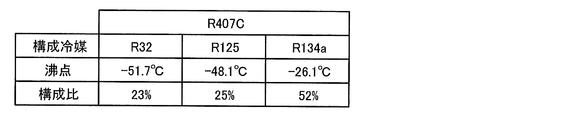
- FIG. 2 is a table showing the boiling point and the composition ratio of the refrigerant that constitutes R407C, which is the non-azeotropic refrigerant in the first embodiment of the present invention.
- the non-azeotropic refrigerant sealed in the refrigerant circuit 10 is R407C.
- R407C is a mixture of R32, R125 and R134a.
- the boiling points are as follows: R32 is -51.7 ° C, R125 is -48.1 ° C, and R134a is -26.1 ° C. That is, among the refrigerants constituting R407C, the boiling point of R134a is the highest.
- the composition ratio is 23% for R32, 25% for R125, and 52% for R134a.
- the non-azeotropic refrigerant stored in the accumulator 15 is mainly a liquid refrigerant separated from the gas refrigerant, and the refrigerant stored in the accumulator 15 has a high ratio of R134a which is difficult to be gasified because the boiling point is high. For this reason, the refrigerant circulating in the refrigerant circuit 10 has a high ratio of R32 and R125.
- the refrigerant density of the non-azeotropic refrigerant changes as the high pressure side pressure and the low pressure side pressure change due to seasonal fluctuation or cooling load fluctuation.
- the high pressure side pressure refers to the pressure of the high pressure refrigerant compressed by the compressor 11
- the low pressure side pressure refers to the pressure of the low pressure refrigerant expanded in the expansion unit 13. Therefore, the amount of refrigerant required in the refrigerant circuit 10 also changes.
- the refrigerant having the amount of the refrigerant required above the maximum amount of refrigerant in consideration of the change in the amount of refrigerant necessary is enclosed so that the capacity loss due to the refrigerant shortage and the overheating operation do not occur under any circumstances. Be done. Therefore, surplus refrigerant generated due to the change of the required refrigerant amount is stored in the accumulator 15.
- the control device 50 controls the refrigeration air conditioner 100 based on measured values of pressure and temperature of each part and various set values.
- the control device 50 grasps the operating state of the refrigeration air conditioner 100 based on the pressure and temperature acquired from the condensation temperature sensor 21, the expansion inlet temperature sensor 22, the low pressure sensor 23, and the evaporation inlet temperature sensor 24.
- the control device 50 adjusts the high pressure according to the temperature of the outdoor air sucked into the condenser 12, the amount of cooling air of the condenser 12, the size of the cooling load, and the power consumption of the compressor 11.
- control device 50 adjusts the low pressure according to the operating frequency of the compressor 11, the amount of cooling air of the evaporator 14, the opening degree of the expansion portion 13 and the like, and maintains the degree of superheat at the outlet of the evaporator 14 at the set degree of superheat.
- the controller 50 has an inspection mode for detecting a refrigerant leak, in addition to the normal operation mode for air conditioning the cooling chamber.
- the inspection mode is a mode in which the refrigerant circuit 10 is operated under inspection conditions for keeping the low pressure of the refrigerant circuit 10 at the set pressure, and the presence or absence of the non-azeotropic refrigerant leakage is determined.
- the controller 50 executes the inspection mode under the condition that continuous operation for a relatively long time is possible. For example, the inspection mode is performed when the temperature of the cooling chamber is higher than the actual temperature of the cooling chamber and the set temperature of the cooling chamber such as after completion of the defrosting operation so that the compressor 11 does not stop (thermo-off) until the state of the refrigeration cycle becomes stable. To be done.
- the inspection mode is performed when the evaporation temperature of the non-azeotropic refrigerant converted from the set pressure is higher than the set temperature of the cooling chamber. Since the thermo-off does not occur, the stable state can be maintained to detect the leakage of the refrigerant.
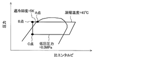
- FIG. 3 is a ph diagram showing the state in the inspection mode in the first embodiment of the present invention.
- the refrigerant circuit 10 is controlled such that the condensation temperature, the degree of subcooling, and the low pressure are stabilized at predetermined values.
- the non-azeotropic refrigerant compressed by the compressor 11 is condensed by the condenser 12, passes through the point A, and is further subcooled to the point B. Thereafter, the non-azeotropic refrigerant is decompressed by the expansion unit 13 and reaches point C. Then, it is evaporated by the evaporator 14 and sucked into the compressor 11.
- the control device 50 performs an operation in which the condensation temperature, the degree of subcooling, and the low pressure become the target values until the pressure and temperature of each part become stable.
- the condensation temperature is 45 ° C., the degree of supercooling 5 K, and the low pressure 0.3 MPa.
- the inspection condition is a condition at which the condensation temperature, the subcooling degree, and the low pressure become target values.
- the condensation temperature is the temperature of the non-azeotropic refrigerant flowing to the condenser 12.
- the condensation temperature is detected by the condensation temperature sensor 21.
- the degree of subcooling is a degree of subcooling of the non-azeotropic refrigerant flowing to the inlet side of the expansion portion 13.
- the degree of subcooling is obtained by subtracting the temperature before expansion detected by the expansion inlet temperature sensor 22 from the condensation temperature detected by the condensation temperature sensor 21.
- the low pressure is the pressure of the non-azeotropic refrigerant flowing to the inlet side of the evaporator 14.
- the low pressure is detected by the low pressure sensor 23.
- the controller 50 controls the operating frequency of the compressor 11 and the fan (not shown) of the condenser 12 so that the low pressure in the inspection mode is higher than the low pressure in the cooling operation in the normal operation mode. Adjust the output etc.
- the controller 50 controls the operating frequency of the compressor 11 and the output of the fan (not shown) of the condenser 12 so that the condensing temperature in the inspection mode is lower than the condensing temperature in the cooling operation in the normal operation mode. Etc. are adjusted.
- the control device 50 makes the number of rotations of the fan blowing to the condenser 12 higher in the inspection mode than in the normal operation mode.
- the condensation temperature of the condenser 12 is lowered, and the degree of subcooling is increased accordingly, so the density of the liquid refrigerant is increased. Therefore, the amount of liquid refrigerant circulating in the refrigerant circuit 10 increases, and the amount of surplus refrigerant remaining in the accumulator 15 decreases.
- control device 50 makes the rotation speed of the compressor 11 higher in the inspection mode than in the normal operation mode. Thereby, the amount of the refrigerant circulating to the refrigerant circuit 10 is increased. Furthermore, the control device 50 makes the opening degree of the expansion portion 13 larger in the inspection mode than in the normal operation mode. Thereby, the amount of the refrigerant circulating to the refrigerant circuit 10 is increased. As described above, the excess refrigerant is reduced from the accumulator 15 and the non-azeotropic refrigerant circulating in the refrigerant circuit 10 is increased to keep the composition ratio of the non-azeotropic refrigerant circulating in the refrigerant circuit 10 uniform. As the inspection condition, instead of the condensation temperature, the high pressure may be a target value.
- the controller 50 is based on the saturation temperature theoretical value determined from the inlet pressure of the non-azeotropic refrigerant flowing to the inlet side of the evaporator 14 and the inlet temperature of the non-azeotropic refrigerant flowing to the inlet side of the evaporator 14. Determine the azeotropic refrigerant leakage. Specifically, when the subtraction value obtained by subtracting the theoretical saturation temperature value from the inlet temperature exceeds the subtraction threshold value, the control device 50 determines that the non-azeotropic refrigerant has leaked.
- the subtraction threshold is, for example, 1.5K. In addition, when the control device 50 continuously detects that the subtraction value exceeds the subtraction threshold for five minutes, it may determine that the refrigerant leaks and output an alarm.
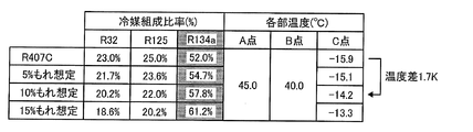
- FIG. 4 is a table showing temperatures of respective portions associated with a change in the composition of R407C which is a non-azeotropic refrigerant in the first embodiment of the present invention.
- the temperature at point A in FIG. 3 is 45 ° C.
- the temperature at point B is 40 ° C.
- the temperature at point C is -15.9 ° C.
- -15.9 ° C. is a theoretical value of the low-pressure pressure saturation temperature when it is assumed that the composition ratio is a set ratio.
- the saturation temperature increases when the low pressure is a constant value.
- the control device 50 determines that the non-azeotropic refrigerant has leaked when a 10% leak is assumed to be 1.7 K where the temperature difference exceeds the subtraction threshold 1.5 K.
- the refrigerant circulating in the refrigerant circuit 10 has a high ratio of R32 and R125, when the non-azeotropic refrigerant leaks in the refrigerant circuit 10, R32 and R125 leak more than R134a. For this reason, as the refrigerant leakage progresses, the composition ratio changes so that the ratio of R134a in all the refrigerant gradually increases. R134a has a higher boiling point than R32 and R125. Therefore, as the composition ratio changes, the saturation temperature increases when the low pressure is a constant value. In the first embodiment, the leakage of the refrigerant is detected using this phenomenon.
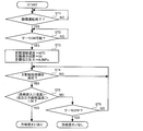
- FIG. 5 is a flowchart showing an operation of the refrigeration air conditioning system 100 according to Embodiment 1 of the present invention.
- the control device 50 first determines whether the defrosting operation has ended (step ST1). If the defrosting operation has not ended (No in step ST1), the process returns to step ST1.
- the control device 50 determines whether the thermo stop is not performed in order to confirm whether the stable period necessary for the inspection is secured (step ST2). .
- the process proceeds to step ST3.
- step ST3 target values of the condensation temperature, the degree of subcooling, and the low pressure are set.
- the control device 50 determines whether or not the condensation temperature, the degree of subcooling, and the low pressure have become target values (step ST4).
- the control device 50 performs an operation in which the condensation temperature, the degree of subcooling, and the low pressure become the target values until the pressure and temperature of each part become stable. If the condensation temperature, the subcooling degree, and the low pressure are not the target values (No in step ST4), the process returns to step ST4.
- the controller 50 determines whether the subtraction value obtained by subtracting the theoretical saturation temperature value from the inlet temperature exceeds the subtraction threshold. It determines (step ST5).
- step ST5 If the subtraction value exceeds the subtraction threshold (Yes in step ST5), the control device 50 determines that the non-azeotropic refrigerant has leaked. On the other hand, if the subtraction value is equal to or less than the subtraction threshold (No in step ST5), the control device 50 determines whether the thermo stop has occurred (step ST6). When the thermo stop is not performed (No in step ST6), the determination is repeated (steps ST4 to ST6). If the thermo stop has occurred due to the cooling in the inspection mode (Yes in step ST6), the control device 50 determines that the non-azeotropic refrigerant has not leaked.
- the refrigerant circuit 10 is operated under the inspection condition to keep the low pressure of the refrigerant circuit 10 at the set pressure, and the state of the refrigerant circuit 10 is stabilized. For this reason, regardless of the pipe length of the refrigerant circuit 10, the low pressure is maintained at the set pressure, so the state of the refrigerant circuit 10 can be stabilized regardless of the pipe length of the refrigerant circuit 10. Therefore, the leakage of the refrigerant can be accurately detected regardless of the pipe length of the refrigerant circuit 10.
- the condensation temperature of the non-azeotropic refrigerant is set to be lower than that in the normal operation mode.
- the amount of refrigerant in the circuit necessary for the operation of the refrigeration air conditioning apparatus 100 changes depending on the ambient temperature accompanying the seasonal fluctuation. Therefore, the refrigerant
- coolant amount is enclosed by the refrigerating air-conditioning apparatus 100. As shown in FIG. For this reason, the surplus refrigerant remains in the pressure vessel such as the accumulator 15 provided in the refrigerant circuit 10 for most of the period of one year.
- the conventional refrigerant shortage detection method compares the theoretical inlet temperature value assuming that the refrigerant is sufficiently present in the refrigeration circuit with the inlet temperature actually measured in a state where the surplus refrigerant is stored in the accumulator or the like. Do. However, even if the refrigerant in the refrigerant circuit leaks, the refrigerant stored in the accumulator flows out into the refrigerant circuit, and the amount of refrigerant circulating in the refrigerant circuit is the excess refrigerant stored in the accumulator. It will not change almost until there is no That is, the inlet temperature to be measured does not change until the amount of the refrigerant larger than the excess refrigerant leaks. Therefore, it is difficult to detect the refrigerant leakage while the amount of leakage is small.
- the condensation temperature of the non-azeotropic refrigerant in the inspection mode, is set to be lower than that in the normal operation mode. As the condensation temperature decreases, the degree of subcooling increases accordingly, and the density of the liquid refrigerant increases. Therefore, the amount of liquid refrigerant circulating in the refrigerant circuit 10 increases, and the amount of surplus refrigerant remaining in the accumulator 15 decreases. As described above, since the inspection is performed in a state where the amount of surplus refrigerant is small, the composition of the non-azeotropic refrigerant flowing in the refrigerant circuit 10 changes only when a small amount of the non-azeotropic refrigerant leaks.
- the leakage of the non-azeotropic refrigerant can be detected from the stage where the amount of the non-azeotropic refrigerant leaking is small.
- the amount of non-azeotropic refrigerant stored in the accumulator 15 is large, even if the non-azeotropic refrigerant circulating in the refrigerant circuit 10 leaks, the non-azeotropic refrigerant flows out from the accumulator 15 into the refrigerant circuit 10 Therefore, the state of the circulating non-azeotropic refrigerant does not change.
- the composition of the non-azeotropic refrigerant flowing in the refrigerant circuit 10 is only when a small amount of the non-azeotropic refrigerant leaks. Change. Therefore, the leakage of the non-azeotropic refrigerant can be detected from the stage where the amount of refrigerant leakage is small. Thereby, even if it is the frozen air conditioner 100 using the fluorocarbon refrigerant
- the low pressure temperature sensor is the evaporation inlet temperature sensor 24 that detects the temperature of the refrigerant flowing into the evaporator 14. Since the non-azeotropic refrigerant has a temperature gradient, the detection accuracy of the refrigerant leakage is improved by performing the determination of the refrigerant leakage using the temperature of the non-azeotropic refrigerant flowing into the evaporator 14. The evaporator 14 also cools the cooling chamber. Thus, by stabilizing the temperature of the room in which the evaporator 14 is installed, the detection accuracy of the refrigerant leakage is enhanced.
- the refrigerant storage amount in the inspection mode is constant regardless of the seasonal fluctuation. For this reason, it is possible to detect the leakage of the non-azeotropic refrigerant from the stage where the amount of leakage of the refrigerant is small, without being affected by the change of the surplus refrigerant amount accompanying the seasonal fluctuation.
- the theoretical inlet temperature of the evaporator of the theoretical refrigeration cycle which is determined by the heat load when it is assumed that the refrigerant is sufficiently present in the refrigerant circuit, and the inlet temperature of the evaporator actually measured. It is judged that the refrigerant is insufficient based on the difference of The change in evaporator inlet temperature is due to the pressure drop in the refrigeration cycle associated with refrigerant leakage. That is, when a change in the inlet temperature of the evaporator is detected, the cooling capacity of the refrigeration air conditioning system is insufficient due to the shortage of the refrigerant. For this reason, when a reduction in cooling capacity such as a refrigerator and an objective air conditioning application is directly linked to the quality of a stored item, the stored item may be deteriorated and broken.
- the non-azeotropic refrigerant in order to detect the leakage of the non-azeotropic refrigerant from the stage where the leakage amount of the refrigerant is small, the non-azeotropic refrigerant is detected only by performing the operation with constant conditions for a short time.
- the refrigerant can be detected at a timing that is necessary for the operation of the refrigeration cycle, such as a pull-down operation after the end of defrosting, and does not affect the quality of stored items. For this reason, it does not lead to the change of the inlet temperature leading to deterioration and failure of the quality of stored goods.
- the state of the theoretical refrigeration cycle changes due to the effect of pressure loss occurring in the on-site piping.
- the conventional refrigeration air conditioning system uses a method of computing a theoretical refrigeration cycle based on heat load, assuming that a necessary amount of refrigerant is present in a refrigeration circuit. For this reason, the theoretical refrigeration cycle determined by calculation and the theoretical refrigeration cycle in actual operation do not match, and the refrigerant leakage can not be detected correctly.
- the operation under constant conditions is performed.
- the refrigerant leaks without being affected by the on-site construction conditions such as changes in high pressure and low pressure due to pressure loss in the on-site piping and changes in the degree of supercooling due to the effect of rising pipe length. It can be detected accurately.
- Embodiment 1 exemplifies the case where the inspection mode is executed under specific conditions that allow continuous operation, such as after completion of the defrosting operation, the in-device temperature is the target in-device temperature. However, control may be performed to continue the operation without stopping the thermo. This ensures that the inspection mode is performed. As described above, in the first embodiment, in the inspection mode, even if the temperature of the air to be cooled reaches the temperature threshold, control may be performed to continue the operation of the refrigerant circuit 10.
- the control device 50 may acquire the inlet temperature a plurality of times at fixed time intervals. In this case, the control device 50 determines that the non-azeotropic refrigerant is leaking when, for example, the plurality of measured values are averaged over a 30-second interval with time and the average value satisfies the determination condition ten consecutive times. Do.
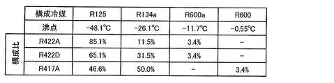
- FIG. 6 is a table showing boiling points and composition ratios of refrigerants constituting the non-azeotropic refrigerants R422A, R422D and R417A according to the second embodiment of the present invention.
- the second embodiment is different from the first embodiment in that leakage can be detected in a plurality of refrigerants.
- the same parts as those of the first embodiment are denoted by the same reference numerals, and the description thereof is omitted. The differences from the first embodiment will be mainly described.
- the configuration of the refrigerant circuit 10 is the same as that of the first embodiment.
- the used refrigerant can be selected by the control device 50, and all of R422A, R422D, and R417A can be adopted.
- the composition ratio of R422A is 85.1% for R125, 11.5% for R134a, and 3.4% for R600a.
- the composition ratio of R422D is 65.1% for R125, 31.5% for R134a, and 3.4% for R600a.
- the compositional ratio of R417A is 46.6% for R125, 50.0% for R134a, and 3.4% for R600.
- R125 The boiling point of R125 is -48.1 ° C
- R134a is -26.1 ° C
- R600a is -11.7 ° C
- R600 is -0.55 ° C. That is, R134a, R600a and R600 have boiling points higher than R125.
- R125 is referred to as a first refrigerant group
- R134a, R600a, and R600 are referred to as a second refrigerant group.
- the composition ratio of the second refrigerant group is 30% or more, and in R422A, the composition ratio of the second refrigerant group is less than 30%.
- R407C illustrated in the first embodiment has R32 and R125 as the first refrigerant group, and R134a having a boiling point higher than R32 and R125 as the second refrigerant group, the composition ratio of the second refrigerant group is 30. % Or more.
- the control device 50 classifies and sets the type of non-azeotropic refrigerant into the first refrigerant group and the second refrigerant group having a boiling point higher than that of the first refrigerant group.
- the subtraction threshold is set based on the type of non-azeotropic refrigerant.
- the subtraction threshold is set based on the composition ratio of the second refrigerant group.
- the subtraction threshold may be associated with a table stored in advance, or may be set individually.
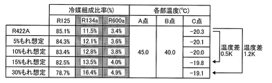
- FIG. 7 is a table showing the temperature of each part according to the composition change of R422A in the second embodiment of the present invention.
- the temperature at point A in FIG. 3 is 45 ° C.
- the temperature at point B is 40 ° C.
- the temperature at point C is ⁇ 20.3 ° C.
- -20.3 ° C. is a theoretical value of saturation temperature of low pressure when it is assumed that the composition ratio is appropriate.
- the saturation temperature increases when the low pressure is a constant value.
- the temperature change at point C is 0.5 K when it leaks 15%.
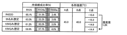
- FIG. 8 is a table showing the temperature of each part according to the change in composition of R422D in the second embodiment of the present invention.
- the temperature at point A in FIG. 3 is 45 ° C.
- the temperature at point B is 40 ° C.
- the temperature at point C is -15.6 ° C.
- -15.6 ° C. is a theoretical value of saturation temperature of low pressure when it is assumed that the composition ratio is appropriate.
- the saturation temperature rises when the low pressure is a constant value.
- the temperature change at point C is 1.2 K when it leaks 15%.
- FIG. 9 is a table showing the temperatures of respective portions according to the composition change of R417A in the second embodiment of the present invention.
- the temperature at point A in FIG. 3 is 45 ° C.
- the temperature at point B is 40 ° C.
- the temperature at point C is ⁇ 11.0 ° C.
- ⁇ 11.0 ° C. is a theoretical value of the saturation temperature of the low pressure when it is assumed that the composition ratio is appropriate.
- the saturation temperature when the low pressure is a constant value rises.
- the temperature change at point C is 1.2 K when 10% leaks and 1.9 K when 15% leaks.
- the subtraction threshold is set based on the composition ratio of the second refrigerant group. For example, in R422A, as shown in FIG. 7, the subtraction threshold value is set to 0.5 K, which is detected when the refrigerant leaks 15%. Further, in R422D, as shown in FIG. 8, the subtraction threshold is set to 1.0 K, so that detection is performed when the refrigerant leaks 10%. In R 417 A, as shown in FIG.
- the subtraction threshold value is set to 1.0 K, so that it is detected when the refrigerant leaks 15%.
- the leak threshold of the plurality of refrigerants can be detected by changing the subtraction threshold based on the composition ratio of the second refrigerant group.
- Control device 50 may execute an inspection mode different from the above-described inspection mode.
- the composition ratio of the second refrigerant group is less than 30% as in R422A
- the temperature change at point C is as small as 0.5 K even if the refrigerant leaks 15%. Therefore, it is necessary to reduce the subtraction threshold value to 0.5 K, but in this case, there is a possibility that the leakage may be erroneously detected due to the measurement variation.
- the subtraction threshold value is 1.0 K, the leakage can not be detected until the temperature difference leaks to nearly 30% at which the temperature difference is 1.2 K. Therefore, depending on the type of refrigerant, a plurality of inspection modes may be used properly.
- control device 50 selects the inlet temperature of the evaporator 14 as in the conventional case.
- a detection mode is executed to determine the presence or absence of leakage based on the difference from the theoretical value.
- control device 50 executes the inspection mode of the first embodiment when a refrigerant having a composition ratio of the second refrigerant group higher than that of the first refrigerant group is selected. Do.
- leakage detection can be performed according to the type of refrigerant, which contributes to a reduction in the amount of refrigerant leakage.
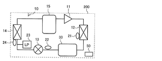
- FIG. 10 is a circuit diagram showing a refrigeration air conditioning system 200 according to Embodiment 3 of the present invention.
- the third embodiment is different from the first embodiment in that the liquid reservoir 33 is provided.
- the same parts as those of the first embodiment are denoted by the same reference numerals, and the description thereof is omitted. The differences from the first embodiment will be mainly described.
- the liquid reservoir 33 is connected between the condenser 12 and the expansion section 13 and stores excess refrigerant.
- the excess refrigerant is stored inside the liquid reservoir 33, and the liquid phase refrigerant flows out from the outlet of the liquid reservoir 33.
- the control device 50 performs the operation of moving the surplus refrigerant out of the non-azeotropic refrigerant flowing in the refrigerant circuit 10 to the accumulator 15 which is the pressure vessel on the low pressure side before the execution of the inspection mode. After, execute the inspection mode.
- the leakage of the refrigerant can be detected.
- leakage detection due to composition change can be performed, and a broader range of product groups can be used. Leakage of refrigerant can be detected.
- leakage may be detected in a plurality of refrigerants.
Landscapes
- Engineering & Computer Science (AREA)
- Physics & Mathematics (AREA)
- Mechanical Engineering (AREA)
- Thermal Sciences (AREA)
- General Engineering & Computer Science (AREA)
- Compression-Type Refrigeration Machines With Reversible Cycles (AREA)
Abstract
L'invention concerne un dispositif de réfrigération et de climatisation qui comprend: un circuit de fluide frigorigène dans lequel un compresseur, un condenseur, une unité d'expansion et un évaporateur sont connectés et dans lequel circule un fluide frigorigène non azéotrope; un capteur de température basse pression qui détecte la température du fluide frigorigène non azéotrope à basse pression dans le circuit de fluide frigorigène; et un dispositif de commande qui a un mode d'inspection pour déterminer la présence d'une fuite de fluide frigorigène non azéotrope à l'aide de la température détectée avec le capteur de température basse pression tout en actionnant le circuit de fluide frigorigène dans des conditions d'inspection qui maintiennent la basse pression du circuit de fluide frigorigène à une pression définie.
Priority Applications (3)
| Application Number | Priority Date | Filing Date | Title |
|---|---|---|---|
| JP2019532298A JP7058657B2 (ja) | 2017-07-27 | 2017-07-27 | 冷凍空調装置及び制御装置 |
| CN201790001747.6U CN212253263U (zh) | 2017-07-27 | 2017-07-27 | 制冷空调装置 |
| PCT/JP2017/027288 WO2019021428A1 (fr) | 2017-07-27 | 2017-07-27 | Dispositif de climatisation et de réfrigération, et dispositif de commande |
Applications Claiming Priority (1)
| Application Number | Priority Date | Filing Date | Title |
|---|---|---|---|
| PCT/JP2017/027288 WO2019021428A1 (fr) | 2017-07-27 | 2017-07-27 | Dispositif de climatisation et de réfrigération, et dispositif de commande |
Publications (1)
| Publication Number | Publication Date |
|---|---|
| WO2019021428A1 true WO2019021428A1 (fr) | 2019-01-31 |
Family
ID=65040488
Family Applications (1)
| Application Number | Title | Priority Date | Filing Date |
|---|---|---|---|
| PCT/JP2017/027288 Ceased WO2019021428A1 (fr) | 2017-07-27 | 2017-07-27 | Dispositif de climatisation et de réfrigération, et dispositif de commande |
Country Status (3)
| Country | Link |
|---|---|
| JP (1) | JP7058657B2 (fr) |
| CN (1) | CN212253263U (fr) |
| WO (1) | WO2019021428A1 (fr) |
Cited By (1)
| Publication number | Priority date | Publication date | Assignee | Title |
|---|---|---|---|---|
| WO2024009394A1 (fr) * | 2022-07-05 | 2024-01-11 | 三菱電機株式会社 | Climatiseur et procédé de détection de fuite de fluide frigorigène |
Citations (3)
| Publication number | Priority date | Publication date | Assignee | Title |
|---|---|---|---|---|
| JPH0886545A (ja) * | 1994-09-14 | 1996-04-02 | Sanyo Electric Co Ltd | 蒸気圧縮式冷凍機 |
| JP2003042655A (ja) * | 2001-07-27 | 2003-02-13 | Toshiba Corp | 冷蔵庫 |
| JP2015135192A (ja) * | 2014-01-16 | 2015-07-27 | 株式会社富士通ゼネラル | 空気調和装置 |
Family Cites Families (1)
| Publication number | Priority date | Publication date | Assignee | Title |
|---|---|---|---|---|
| JP2008025935A (ja) | 2006-07-24 | 2008-02-07 | Daikin Ind Ltd | 空気調和装置 |
-
2017
- 2017-07-27 CN CN201790001747.6U patent/CN212253263U/zh not_active Expired - Fee Related
- 2017-07-27 WO PCT/JP2017/027288 patent/WO2019021428A1/fr not_active Ceased
- 2017-07-27 JP JP2019532298A patent/JP7058657B2/ja not_active Expired - Fee Related
Patent Citations (3)
| Publication number | Priority date | Publication date | Assignee | Title |
|---|---|---|---|---|
| JPH0886545A (ja) * | 1994-09-14 | 1996-04-02 | Sanyo Electric Co Ltd | 蒸気圧縮式冷凍機 |
| JP2003042655A (ja) * | 2001-07-27 | 2003-02-13 | Toshiba Corp | 冷蔵庫 |
| JP2015135192A (ja) * | 2014-01-16 | 2015-07-27 | 株式会社富士通ゼネラル | 空気調和装置 |
Cited By (1)
| Publication number | Priority date | Publication date | Assignee | Title |
|---|---|---|---|---|
| WO2024009394A1 (fr) * | 2022-07-05 | 2024-01-11 | 三菱電機株式会社 | Climatiseur et procédé de détection de fuite de fluide frigorigène |
Also Published As
| Publication number | Publication date |
|---|---|
| JP7058657B2 (ja) | 2022-04-22 |
| JPWO2019021428A1 (ja) | 2020-02-27 |
| CN212253263U (zh) | 2020-12-29 |
Similar Documents
| Publication | Publication Date | Title |
|---|---|---|
| CN111065869B (zh) | 气体泄漏量检测方法以及冷冻装置的运转方法 | |
| JP6475346B2 (ja) | 冷凍サイクル装置 | |
| US11131490B2 (en) | Refrigeration device having condenser unit connected to compressor unit with on-site pipe interposed therebetween and remote from the compressor unit | |
| JP4403300B2 (ja) | 冷凍装置 | |
| US10247459B2 (en) | Refrigeration cycle apparatus | |
| CN111094877B (zh) | 制冷循环装置以及制冷装置 | |
| EP3404345B1 (fr) | Dispositif de circuit de réfrigération | |
| US9453671B2 (en) | Refrigerating and air-conditioning apparatus and method for controlling refrigerating and air-conditioning apparatus | |
| JPWO2017006474A1 (ja) | 冷凍サイクル装置、遠隔監視システム、遠隔監視装置および異常判定方法 | |
| JPWO2019053880A1 (ja) | 冷凍空調装置 | |
| US11293647B2 (en) | Air conditioner | |
| GB2554560A (en) | Refrigeration apparatus | |
| EP2746699A1 (fr) | Dispositif à cycle de réfrigération | |
| GB2562639A (en) | Refrigeration device | |
| JP6739664B2 (ja) | 冷凍空調装置及び制御装置 | |
| JP2948105B2 (ja) | 非共沸混合冷媒を用いた冷凍空調装置 | |
| JP7058657B2 (ja) | 冷凍空調装置及び制御装置 | |
| JP6393181B2 (ja) | 冷凍サイクル装置 | |
| CN107208951A (zh) | 制冷剂量异常检测装置以及制冷装置 | |
| JP2017067397A (ja) | 冷凍装置 | |
| JP7599573B2 (ja) | 冷凍サイクル装置、及び冷凍サイクル装置の制御方法 | |
| JP7603822B2 (ja) | 冷凍サイクル装置、及び冷凍サイクル装置の制御方法 | |
| WO2025243515A1 (fr) | Dispositif à cycle de réfrigération et dispositif de commande |
Legal Events
| Date | Code | Title | Description |
|---|---|---|---|
| 121 | Ep: the epo has been informed by wipo that ep was designated in this application |
Ref document number: 17919229 Country of ref document: EP Kind code of ref document: A1 |
|
| ENP | Entry into the national phase |
Ref document number: 2019532298 Country of ref document: JP Kind code of ref document: A |
|
| NENP | Non-entry into the national phase |
Ref country code: DE |
|
| 122 | Ep: pct application non-entry in european phase |
Ref document number: 17919229 Country of ref document: EP Kind code of ref document: A1 |