WO2019021532A1 - Dispositif de conversion de puissance électrique - Google Patents
Dispositif de conversion de puissance électrique Download PDFInfo
- Publication number
- WO2019021532A1 WO2019021532A1 PCT/JP2018/012829 JP2018012829W WO2019021532A1 WO 2019021532 A1 WO2019021532 A1 WO 2019021532A1 JP 2018012829 W JP2018012829 W JP 2018012829W WO 2019021532 A1 WO2019021532 A1 WO 2019021532A1
- Authority
- WO
- WIPO (PCT)
- Prior art keywords
- conversion device
- power
- power conversion
- semiconductor module
- power semiconductor
- Prior art date
- Legal status (The legal status is an assumption and is not a legal conclusion. Google has not performed a legal analysis and makes no representation as to the accuracy of the status listed.)
- Ceased
Links
Images






Classifications
-
- H—ELECTRICITY
- H02—GENERATION; CONVERSION OR DISTRIBUTION OF ELECTRIC POWER
- H02M—APPARATUS FOR CONVERSION BETWEEN AC AND AC, BETWEEN AC AND DC, OR BETWEEN DC AND DC, AND FOR USE WITH MAINS OR SIMILAR POWER SUPPLY SYSTEMS; CONVERSION OF DC OR AC INPUT POWER INTO SURGE OUTPUT POWER; CONTROL OR REGULATION THEREOF
- H02M7/00—Conversion of AC power input into DC power output; Conversion of DC power input into AC power output
- H02M7/003—Constructional details, e.g. physical layout, assembly, wiring or busbar connections
-
- H—ELECTRICITY
- H05—ELECTRIC TECHNIQUES NOT OTHERWISE PROVIDED FOR
- H05K—PRINTED CIRCUITS; CASINGS OR CONSTRUCTIONAL DETAILS OF ELECTRIC APPARATUS; MANUFACTURE OF ASSEMBLAGES OF ELECTRICAL COMPONENTS
- H05K7/00—Constructional details common to different types of electric apparatus
- H05K7/14—Mounting supporting structure in casing or on frame or rack
- H05K7/1422—Printed circuit boards receptacles, e.g. stacked structures, electronic circuit modules or box like frames
- H05K7/1427—Housings
- H05K7/1432—Housings specially adapted for power drive units or power converters
- H05K7/14329—Housings specially adapted for power drive units or power converters specially adapted for the configuration of power bus bars
-
- H—ELECTRICITY
- H05—ELECTRIC TECHNIQUES NOT OTHERWISE PROVIDED FOR
- H05K—PRINTED CIRCUITS; CASINGS OR CONSTRUCTIONAL DETAILS OF ELECTRIC APPARATUS; MANUFACTURE OF ASSEMBLAGES OF ELECTRICAL COMPONENTS
- H05K7/00—Constructional details common to different types of electric apparatus
- H05K7/20—Modifications to facilitate cooling, ventilating, or heating
- H05K7/2089—Modifications to facilitate cooling, ventilating, or heating for power electronics, e.g. for inverters for controlling motor
- H05K7/20909—Forced ventilation, e.g. on heat dissipaters coupled to components
- H05K7/20918—Forced ventilation, e.g. on heat dissipaters coupled to components the components being isolated from air flow, e.g. hollow heat sinks, wind tunnels or funnels
Definitions
- the present invention relates to a mounting structure of equipment in a power converter, and is particularly suitable for application to a power converter on which a power semiconductor module is mounted.
- the power conversion device installed in a railway vehicle is a device for controlling an electric motor that drives a vehicle such as an electric railway vehicle.
- the power converter is mainly installed under the floor of the vehicle, and converts the power input from the railway overhead line by the switching operation of the main circuit including the plurality of power semiconductor modules.
- the converted power is used to control a railway car motor.
- the main circuit which is a main component of the power conversion device includes, for example, a power semiconductor module having a power switching element, a gate drive device which is a drive circuit thereof, and a filter capacitor for stabilizing DC power input from an overhead wire. (See Patent Document 1).
- the height dimension of the power conversion device in the vertical direction is one of the installation limitations due to the distance to the ground surface. Had become one.
- the present invention has been made in consideration of the above points, and an object of the present invention is to propose a power conversion device which can be easily mounted on a low floor vehicle by suppressing the height in the vertical direction at the time of installation.
- a power semiconductor module in which the upper arm power switching element and the lower arm power switching element are driven according to the conduction mode to the P pole terminal and the N pole terminal;
- a gate drive device for controlling energization of the power semiconductor module through the N pole terminal and the N pole terminal, and a plurality of terminals respectively connected to the P pole terminal and the N pole terminal are formed on the power semiconductor module side
- the filter capacitor is disposed along the predetermined surface.
- the plurality of terminals are disposed in the vicinity of the power semiconductor module, and the plurality of terminals are disposed on the side of the P-pole terminal and the N-pole terminal, and the plurality of thin plate-like bus bars substantially correspond to the predetermined plane. It is characterized in that it is formed in parallel along the vertical direction.
- the vertical height at the time of installation can be suppressed to facilitate installation on a low floor vehicle.
- FIG. 9 A
- FIG. 1 shows a schematic configuration example of a railway vehicle provided with a power conversion device 1 according to a first embodiment.
- This railway vehicle is a low floor vehicle which travels on the track 110 with wheels 109 by power not shown, and comprises a blower 105, a ventilation room 102 and the power conversion device 1 under the floor of the vehicle body 104.
- the power conversion device 1 is housed in a housing 101 mounted under the floor of the vehicle body 104 and, for example, in the case of air cooling, is cooled by exposing the cooling air 103 flowing through the ventilation chamber 102 to the heat dissipation member. .
- the configuration of the power conversion device 1 will be described in detail.
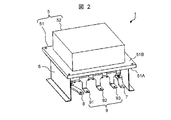
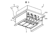
- FIG. 2 to 4 each show a configuration example of the power conversion device 1 shown in FIG. 2 shows an example of the appearance when the power conversion device 1 is viewed from above from above, and FIG. 3 shows an example of the appearance when the power conversion device 1 is viewed from below.
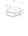
- FIG. 4 shows an example of the appearance of the power conversion device 1 as viewed from slightly above.
- the power conversion device 1 is a device that generates direct current from single phase alternating current or generates three phase alternating current from direct current. Generally, the former is called a converter while the latter is called an inverter ing.
- the converter has a function of converting a single-phase AC voltage from an AC power supply into a DC voltage and charging the filter capacitor 3 for DC voltage smoothing, and is constituted by a two-phase leg.
- the inverter has a function of converting the DC voltage charged in the filter capacitor 3 into an AC voltage by continuously changing the ON / OFF ratio of each power switching element provided in the power semiconductor module. Construct a phase leg.
- the inverter generates three-phase alternating current, and the three-phase alternating current is supplied to each power switching element of the power semiconductor module via U-phase bus bar 91, V-phase bus bar 92 and W-phase bus bar 93.
- a motor (not shown) mounted on a truck installed under the floor is driven. Both the converter and the inverter perform power conversion by controlling conduction of each power switching element.
- a Si-IGBT which is characterized in that the ON resistance and the drive current are small and the switching speed is fast.
- a SiC-MOSFET capable of higher speed switching operation may be adopted.
- the power converter 1 basically includes a support frame 6, a power semiconductor module, a cooler 5, bus bars 7, 8 and 9, a filter capacitor 3 and a gate drive device 4.
- the power semiconductor module 2 includes, for example, U-phase, V-phase and W-phase P poles and N poles power switching elements. Each power switching element generates heat when it is energized and disconnected. The details of the power semiconductor module 2 will be described later.
- the cooler 5 has a function of cooling a power semiconductor module that consumes a large amount of electric power and generates heat at the time of energization and interruption.
- the cooler 5 can adopt an air cooling type or a water cooling type.
- As the air cooling system a radiator system, a heat pipe system or a fin system can be adopted.
- the cooler 5 includes, for example, a rectangular flat cooling block 51 and a box-shaped heat dissipation member 52 disposed substantially at the center of one surface (corresponding to a surface facing upward in the drawing) of the cooling block 51. Prepare.
- the coolers 5 are respectively supported by the support frames 6 near opposite sides of the opposing rectangle on the other surface 51 A (corresponding to the surface facing downward in the drawing) of the cooling block 51.
- the power semiconductor module 2 is disposed along the other surface 51A.
- the other surface 51A is also referred to as "element mounting surface”.
- the power semiconductor module 2 is a basic frame that constitutes the power conversion device 1, and the support frame 6 is used as a function thereof when being fixed to the housing 101 or holding the cooler 5 and other components.
- These support frames 6 are rectangular flat members fixed so as to be substantially upright from the other surface 51A of the cooling block 51, and the other surface 51A of the cooling block 51 in the flat plate portion.
- the other side member which is not in contact with is bent outward in a direction parallel to the other surface 51A.
- one surface of the other side member configured to be bent is fixed to the bottom.
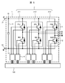
- FIG. 5 shows a configuration example of the main circuit of the power conversion device 1 and the control logic unit 100.
- alternating current type and direct current type exist in a railway feeding system.
- AC motors and DC motors are also present in the main motor. Therefore, depending on the combination of the feeding system and the motor, the power converter 1 may have either an inverter alone or a converter alone or a combination of both.
- an inverter applied to a combination of a DC feeding system and an AC motor will be described.
- the main circuit in the present embodiment is configured to have a filter capacitor 3 connected in an electric circuit path between P pole bus bar 7 which is a DC terminal and N pole bus bar 8 and a three-phase inverter. .
- the three-phase inverter converts the input direct current into a three-phase alternating current of an arbitrary frequency and an arbitrary voltage, and outputs a three-phase alternating current to the alternating current terminals U, V, W.
- the three-phase inverter includes six groups of power switching elements (PU, NU, PV, NV, PW, NW) of U phase 211, V phase 212, and W phase 213.
- the power switching element of each phase comprises an element and a free wheeling diode connected in parallel to the element.
- the circuit symbol is a Si-IGBT as an example as a power switching element, but may be a SiC-MOSFET instead.
- the control logic unit 100 is provided separately from the power conversion device 1, and outputs a control signal to the power conversion device 1 via the gate drive device 4 at the time of energization control.
- the control logic unit 100 drives each power switching element of the power semiconductor module 2 by this control signal.
- the gate drive device 4 is disposed on the side opposite to the cooler 5 across the filter capacitor 3.
- the electronic components to be mounted may malfunction or have a short life due to the influence of heat.
- the gate drive device 4 is not affected by the heat from the surrounding heat generating components. It is desirable to arrange in the position which can be avoided.
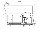
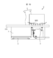
- FIG. 6 is a cross-sectional view showing an example of a basic configuration of the power conversion device 1
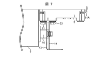
- FIG. 7 is an enlarged view of a portion of the range W shown in FIG.
- FIG. 8 is a perspective view showing a configuration example when the main circuit portion of the power conversion device 1 shown in FIG. 2 is viewed from the element mounting surface side.
- FIGS. 9A and 9B are a plan view and a circuit diagram showing a configuration example of the power semiconductor module 2, respectively.
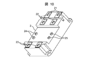
- FIG. 10 is a perspective view of the power semiconductor module 2 shown in FIG. 9 (A).
- 2iN1 means that the element group 11 of the P-pole upper arm and the element group 12 of the N-pole lower arm shown in FIG. 9B are contained in one package.
- One of the features of the power semiconductor module 2 of such a 2iN1 package is that the P-pole terminal 21 and the N-pole terminal 22 can be disposed close to each other as shown in FIG. 9A and FIG.
- the package is provided with a P pole terminal 21, an N pole terminal 22 and an M pole terminal 23, and signal input terminals 24 and 25.
- the signal input terminal 24 is a terminal for driving the element group 11 of the upper arm
- the signal input terminal 25 is a terminal for driving the element group 12 of the lower arm.
- the P-pole terminal 21 and the N-pole terminal 22 are attached to the cooler 5 provided with the cooling block 51 and the heat dissipation member 52 so that the P-pole terminal 21 and the N-pole terminal 22 face inward. It is mounted to be oriented.
- the bus bars 7, 8, 9, 13 and 14 are provided for electrical connection with an external device.
- the P pole bus bar 7 and the N pole bus bar 8 respectively represent end portions of the bus bars 13 and 14.
- the bus bars 7, 8, 9, 13 and 14 use copper having a small volume resistivity as a material and have a large conductor cross-sectional area. Especially when weight reduction is required, aluminum may be adopted as the material.
- each of the P pole terminal 21 and the N pole terminal 22 of the power semiconductor module 2 and each terminal 10 of the filter capacitor 3 is a thin flat bus bar 13, 14 with a film for insulation applied. It is secured by keeping it in close proximity. The presence of the bus bars 13 and 14 can reduce the inductance of the main circuit.
- P pole thin plate bus bar 13 and N pole thin plate bus bar 14 for electrically connecting power semiconductor module 2 and filter capacitor 3 to P pole terminal 21 and N pole terminal 22, respectively, as shown in FIG. are vertically raised with respect to the mounting surface of the power semiconductor module 2 and fixed in close proximity to each other in the opposite direction. This is to reduce the inductance of the P pole thin plate bus bar 13 and the N pole thin bus bar 14. Although the inductance can be reduced as the distance between the P-pole thin plate-like bus bar 13 and the N-pole thin plate-like bus bar 14 decreases, such a constitution lowers the insulation withstand voltage and becomes a restriction.
- the filter capacitor 3 is provided in the vicinity of the power semiconductor module 2 along the element mounting surface 51A of the cooling block 51 of the cooler 5 along the longitudinal direction of the power semiconductor module 2, and the plurality of terminals 10 is P It is arrange
- the gate drive device 4 shown in FIG. 6 there is a possibility that the electronic components to be mounted may malfunction due to the influence of heat and the life may be shortened.
- the power semiconductor module 2, the electric wire, the bus bar, and the like may generate heat by themselves, and the vicinity thereof may have a high temperature. Therefore, the gate drive device 4 is required to be disposed so as to avoid the influence of heat from the surrounding heat generating components, and therefore, the gate drive device 4 is disposed immediately below the filter capacitor 3 in the orientation of the diagrams shown in FIGS.
- the filter capacitor 3 and the gate drive device 4 overlap on the terminal surface side of the power semiconductor module 2 (immediately below the power semiconductor module 2 in the direction of the diagrams shown in FIGS. 6 and 7). Since the power semiconductor module 2 is not provided, the height of the power semiconductor module 2 and the space insulation distance with the gate drive device 4 can be ignored. Therefore, as shown in FIG. 6, the height dimension A in the vertical direction of the power conversion device 1 according to the present embodiment is minimized, and mounting on a low floor vehicle becomes easier.
- the distance B between the P pole terminal 21 and the N pole terminal 22 of the power semiconductor module 2 and the terminal 10 of the filter capacitor 3 can be made shortest, the inductance of the main circuit is reduced. be able to.
- V L ⁇ di / dt
- the power switching element may be damaged or the life thereof may be shortened, resulting in a restriction that the current which can be supplied to the power switching element may be reduced.
- a plurality of power semiconductor modules 2 may be arranged in parallel and used.
- the power converter 1A according to the second embodiment performs substantially the same operation as that of the power converter 1 according to the first embodiment. Descriptions of similar configurations and operations will be omitted, and hereinafter, differences will be mainly described.
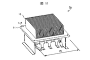
- FIG. 11 is a perspective view showing a configuration example of a power conversion device 1A according to the second embodiment.
- a fin system is adopted for the heat dissipation member 52 of the cooler 5.
- the mounting directions of the power semiconductor module 2 and the planar radiation fin 15 are made to coincide. That is, the radiation fin 15 is attached along the arrangement direction of the P pole terminal 21 and the N pole terminal 22 in the power semiconductor module 2.
- the configurations of the P pole thin plate bus bar 13 and the N pole thin plate bus bar 14 can be simplified, and the width dimension W of the cooling block 51 As a result, the passage cross-sectional area of the ventilation room 102 (see FIG. 1) can be reduced. Thereby, the power converter 1A can be further miniaturized.
- a power conversion device 1B according to a third embodiment has substantially the same configuration as the power conversion device 1 according to the first embodiment and performs substantially the same operation. Descriptions of similar configurations and operations will be omitted, and hereinafter, differences will be mainly described.
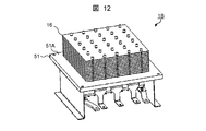
- FIG. 12 is a perspective view showing a configuration example of a power conversion device 1B according to the third embodiment.
- a heat pipe system is adopted for the heat dissipation member 52 of the cooler 5.
- a power conversion device 1C according to a fourth embodiment has substantially the same configuration as the power conversion device 1 according to the first embodiment and performs substantially the same operation. Descriptions of similar configurations and operations will be omitted, and hereinafter, differences will be mainly described.
- FIG. 13 is a perspective view showing a configuration example of a power conversion device 1C according to the fourth embodiment.
- a radiator system is adopted for the heat dissipation member 52 of the cooler 5.
- a power conversion device 1D according to a fifth embodiment has substantially the same configuration as the power conversion device 1 according to the first embodiment and performs substantially the same operation. Descriptions of similar configurations and operations will be omitted, and hereinafter, differences will be mainly described.
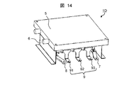
- FIG. 14 is a perspective view showing a configuration example of a power conversion device 1D according to the fifth embodiment.
- a water cooling type cooler 5 is employed instead of the cooler 5 of the form of the previous embodiment.
- the water cooling system does not need to have the heat dissipation member 52 exposed to the cooling air 103 in the cooler 5.
- the power converter 1D can be thinner.
- a power conversion device 1E according to a sixth embodiment has substantially the same configuration as the power conversion device 1 according to the first embodiment and performs substantially the same operation. Descriptions of similar configurations and operations will be omitted, and hereinafter, differences will be mainly described.
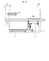
- FIG. 15 is a plan view showing a configuration example of a power conversion device 1E according to the sixth embodiment.
- the filter capacitor 3 is disposed on the windward side of the power semiconductor module 2.
- the filter capacitor 3 since the filter capacitor 3 has a lower allowable temperature than the power semiconductor module 2, the filter capacitor 3 is disposed on the windward side of the cooling air CA of the power semiconductor module 2 that generates heat as indicated by the symbol SH. It can be used even under high ambient temperature.
- a power conversion device 1F according to a seventh embodiment has substantially the same configuration as the power conversion device 1 according to the first embodiment and performs substantially the same operation. Descriptions of similar configurations and operations will be omitted, and hereinafter, differences will be mainly described.
- FIG. 16 is a plan view showing a partial configuration example of a power conversion device 1F according to the seventh embodiment.
- the terminal 10 of the filter capacitor 3 is disposed at a position eccentric to the center of the filter capacitor 3 in the vertical direction of the element mounting surface 51A. That is, the dimension C from the element mounting surface 51A of the cooling block 51 in the filter capacitor 3 to the center of the terminal 10 in the vertical direction and the element mounting surface 51A in the filter capacitor 3 are opposite to the surface in contact with the element mounting surface 51A.
- the dimension D from the side surface to the center is not equal.
- the distance B between the P pole terminal 21 or the N pole terminal 22 of the power semiconductor module 2 and the terminal 10 of the filter capacitor 3 is minimized by securing the space insulation distance and the creepage distance.
- the inductance L of the main circuit can be reduced.
- a power conversion device 1G according to an eighth embodiment has substantially the same configuration as the power conversion device 1 according to the first embodiment and performs substantially the same operation. Descriptions of similar configurations and operations will be omitted, and hereinafter, differences will be mainly described.
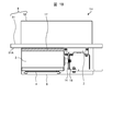
- FIG. 17 is a plan view showing a configuration example of a power conversion device 1G according to the eighth embodiment.
- an air gap S is provided between the surface of the cooling block 51 facing the filter capacitor 3 and the surface of the filter capacitor 3 facing the cooling block 51.
- the air gap S is provided on the entire surface or a part of the surface where the filter capacitor 3 and the cooling block 51 face each other.
- the filter capacitor 3 has a lower allowable temperature than the power semiconductor module 2
- the cooling air passes through the air gap S even when the temperature of the cooling block 51 exceeds the allowable temperature of the filter capacitor 3. Cooling efficiency is further improved.
- a fan may be provided in the support frame 6 or the housing 101, cooling air may be circulated in the housing 101, and the cooling air may pass through the air gap S.
- a power conversion device 1H according to a ninth embodiment has substantially the same configuration as the power conversion device 1G according to the eighth embodiment and performs substantially the same operation. Descriptions of similar configurations and operations will be omitted, and hereinafter, differences will be mainly described.
- FIG. 18 is a plan view showing a configuration example of a power conversion device 1H according to the ninth embodiment.
- the air gap S is provided between the surface of the cooling block 51 facing the filter capacitor 3 and the surface of the filter capacitor 3 facing the cooling block 51 as in the eighth embodiment.
- the heat insulating member 17 is filled in the air gap S.
- the heat insulating member 17 filled in the space S is provided on the entire surface or a part of the surface where the filter capacitor 3 and the cooling block 51 face each other.
- a power conversion device 1I according to a tenth embodiment has substantially the same configuration as the power conversion device 1 according to the first embodiment and performs substantially the same operation. Descriptions of similar configurations and operations will be omitted, and hereinafter, differences will be mainly described.
- FIG. 19 is a plan view showing a configuration example of a power conversion device 1I according to the tenth embodiment.
- the heat dissipation member 52 of the cooler 5 for cooling the heat generation SH by the power semiconductor module 2 is provided on substantially the upper surface of the element mounting surface which is the contact surface between the power semiconductor module 2 and the cooling block 51. It is done.
- the power converter 1I can be reduced in weight, and the center of gravity position is as close to the center of the power converter 1I as possible. Balance can be improved.
- the present invention can be widely applied to a power converter on which a power semiconductor module is mounted.
Landscapes
- Engineering & Computer Science (AREA)
- Microelectronics & Electronic Packaging (AREA)
- Power Engineering (AREA)
- Physics & Mathematics (AREA)
- Thermal Sciences (AREA)
- Inverter Devices (AREA)
Abstract
Dans la présente invention, des barres omnibus en forme de plaque mince de pôle P et de pôle N, formées pour se tenir dans une direction perpendiculaire à une surface de fixation d'un module à semi-conducteur de puissance 2-en-1, sont fixées adjacentes audit module à semi-conducteur de puissance de manière à se faire face. Lesdites barres omnibus en forme de plaque mince sont connectées à des bornes qui sont disposées sur un côté d'un condensateur de filtrage à un décalage par rapport au module à semi-conducteur de puissance.
Priority Applications (3)
| Application Number | Priority Date | Filing Date | Title |
|---|---|---|---|
| JP2019532364A JP6837554B2 (ja) | 2017-07-28 | 2018-03-28 | 電力変換装置 |
| EP18837405.2A EP3661042A4 (fr) | 2017-07-28 | 2018-03-28 | Dispositif de conversion de puissance électrique |
| CN201880036509.8A CN110710094B (zh) | 2017-07-28 | 2018-03-28 | 电力变换装置 |
Applications Claiming Priority (2)
| Application Number | Priority Date | Filing Date | Title |
|---|---|---|---|
| JP2017147141 | 2017-07-28 | ||
| JP2017-147141 | 2017-07-28 |
Publications (1)
| Publication Number | Publication Date |
|---|---|
| WO2019021532A1 true WO2019021532A1 (fr) | 2019-01-31 |
Family
ID=65039506
Family Applications (1)
| Application Number | Title | Priority Date | Filing Date |
|---|---|---|---|
| PCT/JP2018/012829 Ceased WO2019021532A1 (fr) | 2017-07-28 | 2018-03-28 | Dispositif de conversion de puissance électrique |
Country Status (4)
| Country | Link |
|---|---|
| EP (1) | EP3661042A4 (fr) |
| JP (1) | JP6837554B2 (fr) |
| CN (1) | CN110710094B (fr) |
| WO (1) | WO2019021532A1 (fr) |
Cited By (5)
| Publication number | Priority date | Publication date | Assignee | Title |
|---|---|---|---|---|
| JP2020184847A (ja) * | 2019-05-09 | 2020-11-12 | 三菱電機株式会社 | 電力変換装置 |
| JP2021022972A (ja) * | 2019-07-25 | 2021-02-18 | 富士電機株式会社 | 電力変換装置 |
| CN113574787A (zh) * | 2019-03-27 | 2021-10-29 | 日立安斯泰莫株式会社 | 功率转换装置和功率转换装置的制造方法 |
| WO2023079685A1 (fr) * | 2021-11-05 | 2023-05-11 | 東芝三菱電機産業システム株式会社 | Sous-module de dispositif de conversion de puissance |
| WO2023188043A1 (fr) * | 2022-03-29 | 2023-10-05 | 三菱電機株式会社 | Dispositif de conversion de puissance |
Citations (5)
| Publication number | Priority date | Publication date | Assignee | Title |
|---|---|---|---|---|
| JPH11251499A (ja) | 1998-03-06 | 1999-09-17 | Hitachi Ltd | 電力変換装置 |
| JP2014096910A (ja) * | 2012-11-08 | 2014-05-22 | Honda Motor Co Ltd | 電力変換装置 |
| US20140321090A1 (en) * | 2012-01-05 | 2014-10-30 | Valeo Equipements Electriques Moteur | Device for assembling capacitors for an electronic converter |
| JP2015084609A (ja) * | 2013-10-25 | 2015-04-30 | 三菱電機株式会社 | 接続導体の冷却装置及びそれを用いた電力変換装置 |
| JP2016067078A (ja) * | 2014-09-23 | 2016-04-28 | 株式会社デンソー | 電力変換装置 |
Family Cites Families (13)
| Publication number | Priority date | Publication date | Assignee | Title |
|---|---|---|---|---|
| DE19732402B4 (de) * | 1997-07-28 | 2004-07-15 | Danfoss Drives A/S | Elektrische Busanordnung zur Gleichstromversorgung von Schaltungselementen eines Wechselrichters |
| JP3229931B2 (ja) * | 1997-09-08 | 2001-11-19 | 三菱電機株式会社 | 3レベル電力変換装置 |
| JP3950836B2 (ja) * | 2003-10-16 | 2007-08-01 | 株式会社東芝 | 車両用制御装置 |
| JP2009083571A (ja) * | 2007-09-28 | 2009-04-23 | Mitsubishi Heavy Ind Ltd | インバータ一体型電動圧縮機 |
| US7869208B2 (en) * | 2008-12-31 | 2011-01-11 | Caterpillar Inc | Electronics component packaging for power converter |
| CA2766956C (fr) * | 2009-07-06 | 2015-04-28 | Mitsubishi Electric Corporation | Dispositif de conversion de puissance |
| JP5807516B2 (ja) * | 2011-11-09 | 2015-11-10 | 株式会社明電舎 | 電力変換装置及び電力変換装置における導体の配置方法 |
| CN103065805B (zh) * | 2013-01-08 | 2017-12-19 | 周旺龙 | 一种矩形方块状有散热面的铝电解电容器模组及结构 |
| CN103825528A (zh) * | 2014-03-13 | 2014-05-28 | 杭州明果教育咨询有限公司 | 一种低速电动汽车用集成化封装的电机控制器 |
| JP6340907B2 (ja) * | 2014-05-16 | 2018-06-13 | 日産自動車株式会社 | 電力変換装置 |
| CN105406791A (zh) * | 2014-09-10 | 2016-03-16 | 周旺龙 | 一种电动车辆电机控制器及控制器总成的结构方式 |
| DE102015219643A1 (de) * | 2015-10-09 | 2017-04-27 | Conti Temic Microelectronic Gmbh | Elektromotor-Wechselrichter |
| CN205666751U (zh) * | 2016-05-20 | 2016-10-26 | 珠海九源电力电子科技有限公司 | 一种基于竖装叠层母排的变流器模组 |
-
2018
- 2018-03-28 EP EP18837405.2A patent/EP3661042A4/fr not_active Withdrawn
- 2018-03-28 JP JP2019532364A patent/JP6837554B2/ja active Active
- 2018-03-28 CN CN201880036509.8A patent/CN110710094B/zh active Active
- 2018-03-28 WO PCT/JP2018/012829 patent/WO2019021532A1/fr not_active Ceased
Patent Citations (5)
| Publication number | Priority date | Publication date | Assignee | Title |
|---|---|---|---|---|
| JPH11251499A (ja) | 1998-03-06 | 1999-09-17 | Hitachi Ltd | 電力変換装置 |
| US20140321090A1 (en) * | 2012-01-05 | 2014-10-30 | Valeo Equipements Electriques Moteur | Device for assembling capacitors for an electronic converter |
| JP2014096910A (ja) * | 2012-11-08 | 2014-05-22 | Honda Motor Co Ltd | 電力変換装置 |
| JP2015084609A (ja) * | 2013-10-25 | 2015-04-30 | 三菱電機株式会社 | 接続導体の冷却装置及びそれを用いた電力変換装置 |
| JP2016067078A (ja) * | 2014-09-23 | 2016-04-28 | 株式会社デンソー | 電力変換装置 |
Non-Patent Citations (1)
| Title |
|---|
| See also references of EP3661042A4 |
Cited By (11)
| Publication number | Priority date | Publication date | Assignee | Title |
|---|---|---|---|---|
| CN113574787A (zh) * | 2019-03-27 | 2021-10-29 | 日立安斯泰莫株式会社 | 功率转换装置和功率转换装置的制造方法 |
| JP2020184847A (ja) * | 2019-05-09 | 2020-11-12 | 三菱電機株式会社 | 電力変換装置 |
| US11622478B2 (en) | 2019-05-09 | 2023-04-04 | Mitsubishi Electric Corporation | Power converter having improved cooling |
| JP2021022972A (ja) * | 2019-07-25 | 2021-02-18 | 富士電機株式会社 | 電力変換装置 |
| JP7408941B2 (ja) | 2019-07-25 | 2024-01-09 | 富士電機株式会社 | 電力変換装置 |
| WO2023079685A1 (fr) * | 2021-11-05 | 2023-05-11 | 東芝三菱電機産業システム株式会社 | Sous-module de dispositif de conversion de puissance |
| JP7303387B1 (ja) * | 2021-11-05 | 2023-07-04 | 東芝三菱電機産業システム株式会社 | 電力変換装置のサブモジュール |
| US12451816B2 (en) | 2021-11-05 | 2025-10-21 | Tmeic Corporation | Sub-module of power conversion device |
| WO2023188043A1 (fr) * | 2022-03-29 | 2023-10-05 | 三菱電機株式会社 | Dispositif de conversion de puissance |
| JPWO2023188043A1 (fr) * | 2022-03-29 | 2023-10-05 | ||
| JP7570559B2 (ja) | 2022-03-29 | 2024-10-21 | 三菱電機株式会社 | 電力変換装置 |
Also Published As
| Publication number | Publication date |
|---|---|
| EP3661042A4 (fr) | 2021-03-31 |
| JPWO2019021532A1 (ja) | 2020-07-27 |
| EP3661042A1 (fr) | 2020-06-03 |
| JP6837554B2 (ja) | 2021-03-03 |
| CN110710094A (zh) | 2020-01-17 |
| CN110710094B (zh) | 2021-07-27 |
Similar Documents
| Publication | Publication Date | Title |
|---|---|---|
| US9270199B2 (en) | Power conversion apparatus with a laminated bus bar comprising an exposed heat radiating portion | |
| JP6429720B2 (ja) | 電力変換装置及び鉄道車両 | |
| JP6296888B2 (ja) | 電力変換装置 | |
| US10177676B2 (en) | Power converter | |
| JP6429721B2 (ja) | 電力変換装置及び鉄道車両 | |
| JP6837554B2 (ja) | 電力変換装置 | |
| JP2012115128A (ja) | スイッチングモジュール | |
| JP5440634B2 (ja) | 電力変換装置 | |
| CN113632364B (zh) | 电力变换单元 | |
| JP6498370B2 (ja) | 電力変換装置 | |
| JP6526361B2 (ja) | 電力変換装置 | |
| JP2004186504A (ja) | 半導体装置 | |
| WO2019146179A1 (fr) | Dispositif de conversion de puissance et véhicule ferroviaire électrique équipé du dispositif de conversion de puissance | |
| JP5218307B2 (ja) | 冷却装置付きパワーモジュール | |
| JP5550572B2 (ja) | 電力変換装置 | |
| JP5491784B2 (ja) | 鉄道車両電動機駆動用インバータ装置 | |
| JP2015076933A (ja) | 電力変換装置 | |
| CN110168909A (zh) | 电力变换装置 | |
| JP2004336845A (ja) | 車載電力変換装置 | |
| JP6849807B2 (ja) | 電力変換装置及びその冷却方法 | |
| JP4424918B2 (ja) | 電力変換装置 | |
| JP6713246B2 (ja) | 電力変換装置 | |
| JP2003023778A (ja) | 車両用電力変換装置 | |
| JP2019134080A (ja) | 半導体モジュール | |
| CN202652097U (zh) | 半导体装置 |
Legal Events
| Date | Code | Title | Description |
|---|---|---|---|
| 121 | Ep: the epo has been informed by wipo that ep was designated in this application |
Ref document number: 18837405 Country of ref document: EP Kind code of ref document: A1 |
|
| ENP | Entry into the national phase |
Ref document number: 2019532364 Country of ref document: JP Kind code of ref document: A |
|
| NENP | Non-entry into the national phase |
Ref country code: DE |
|
| WWE | Wipo information: entry into national phase |
Ref document number: 2018837405 Country of ref document: EP |