WO2019021537A1 - 複合材成形治具及び複合材成形方法 - Google Patents
複合材成形治具及び複合材成形方法 Download PDFInfo
- Publication number
- WO2019021537A1 WO2019021537A1 PCT/JP2018/014177 JP2018014177W WO2019021537A1 WO 2019021537 A1 WO2019021537 A1 WO 2019021537A1 JP 2018014177 W JP2018014177 W JP 2018014177W WO 2019021537 A1 WO2019021537 A1 WO 2019021537A1
- Authority
- WO
- WIPO (PCT)
- Prior art keywords
- composite material
- panel
- sheet
- composite
- plate
- Prior art date
- Legal status (The legal status is an assumption and is not a legal conclusion. Google has not performed a legal analysis and makes no representation as to the accuracy of the status listed.)
- Ceased
Links
Images




Classifications
-
- B—PERFORMING OPERATIONS; TRANSPORTING
- B29—WORKING OF PLASTICS; WORKING OF SUBSTANCES IN A PLASTIC STATE IN GENERAL
- B29C—SHAPING OR JOINING OF PLASTICS; SHAPING OF MATERIAL IN A PLASTIC STATE, NOT OTHERWISE PROVIDED FOR; AFTER-TREATMENT OF THE SHAPED PRODUCTS, e.g. REPAIRING
- B29C33/00—Moulds or cores; Details thereof or accessories therefor
- B29C33/44—Moulds or cores; Details thereof or accessories therefor with means for, or specially constructed to facilitate, the removal of articles, e.g. of undercut articles
- B29C33/48—Moulds or cores; Details thereof or accessories therefor with means for, or specially constructed to facilitate, the removal of articles, e.g. of undercut articles with means for collapsing or disassembling
- B29C33/50—Moulds or cores; Details thereof or accessories therefor with means for, or specially constructed to facilitate, the removal of articles, e.g. of undercut articles with means for collapsing or disassembling elastic or flexible
- B29C33/505—Moulds or cores; Details thereof or accessories therefor with means for, or specially constructed to facilitate, the removal of articles, e.g. of undercut articles with means for collapsing or disassembling elastic or flexible cores or mandrels, e.g. inflatable
-
- B—PERFORMING OPERATIONS; TRANSPORTING
- B29—WORKING OF PLASTICS; WORKING OF SUBSTANCES IN A PLASTIC STATE IN GENERAL
- B29C—SHAPING OR JOINING OF PLASTICS; SHAPING OF MATERIAL IN A PLASTIC STATE, NOT OTHERWISE PROVIDED FOR; AFTER-TREATMENT OF THE SHAPED PRODUCTS, e.g. REPAIRING
- B29C33/00—Moulds or cores; Details thereof or accessories therefor
- B29C33/38—Moulds or cores; Details thereof or accessories therefor characterised by the material or the manufacturing process
- B29C33/40—Plastics, e.g. foam or rubber
-
- B—PERFORMING OPERATIONS; TRANSPORTING
- B29—WORKING OF PLASTICS; WORKING OF SUBSTANCES IN A PLASTIC STATE IN GENERAL
- B29C—SHAPING OR JOINING OF PLASTICS; SHAPING OF MATERIAL IN A PLASTIC STATE, NOT OTHERWISE PROVIDED FOR; AFTER-TREATMENT OF THE SHAPED PRODUCTS, e.g. REPAIRING
- B29C39/00—Shaping by casting, i.e. introducing the moulding material into a mould or between confining surfaces without significant moulding pressure; Apparatus therefor
- B29C39/02—Shaping by casting, i.e. introducing the moulding material into a mould or between confining surfaces without significant moulding pressure; Apparatus therefor for making articles of definite length, i.e. discrete articles
- B29C39/10—Shaping by casting, i.e. introducing the moulding material into a mould or between confining surfaces without significant moulding pressure; Apparatus therefor for making articles of definite length, i.e. discrete articles incorporating preformed parts or layers, e.g. casting around inserts or for coating articles
-
- B—PERFORMING OPERATIONS; TRANSPORTING
- B29—WORKING OF PLASTICS; WORKING OF SUBSTANCES IN A PLASTIC STATE IN GENERAL
- B29C—SHAPING OR JOINING OF PLASTICS; SHAPING OF MATERIAL IN A PLASTIC STATE, NOT OTHERWISE PROVIDED FOR; AFTER-TREATMENT OF THE SHAPED PRODUCTS, e.g. REPAIRING
- B29C41/00—Shaping by coating a mould, core or other substrate, i.e. by depositing material and stripping-off the shaped article; Apparatus therefor
- B29C41/34—Component parts, details or accessories; Auxiliary operations
- B29C41/38—Moulds, cores or other substrates
-
- B—PERFORMING OPERATIONS; TRANSPORTING
- B29—WORKING OF PLASTICS; WORKING OF SUBSTANCES IN A PLASTIC STATE IN GENERAL
- B29C—SHAPING OR JOINING OF PLASTICS; SHAPING OF MATERIAL IN A PLASTIC STATE, NOT OTHERWISE PROVIDED FOR; AFTER-TREATMENT OF THE SHAPED PRODUCTS, e.g. REPAIRING
- B29C43/00—Compression moulding, i.e. applying external pressure to flow the moulding material; Apparatus therefor
- B29C43/02—Compression moulding, i.e. applying external pressure to flow the moulding material; Apparatus therefor of articles of definite length, i.e. discrete articles
- B29C43/10—Isostatic pressing, i.e. using non-rigid pressure-exerting members against rigid parts or dies
-
- B—PERFORMING OPERATIONS; TRANSPORTING
- B29—WORKING OF PLASTICS; WORKING OF SUBSTANCES IN A PLASTIC STATE IN GENERAL
- B29C—SHAPING OR JOINING OF PLASTICS; SHAPING OF MATERIAL IN A PLASTIC STATE, NOT OTHERWISE PROVIDED FOR; AFTER-TREATMENT OF THE SHAPED PRODUCTS, e.g. REPAIRING
- B29C43/00—Compression moulding, i.e. applying external pressure to flow the moulding material; Apparatus therefor
- B29C43/32—Component parts, details or accessories; Auxiliary operations
-
- B—PERFORMING OPERATIONS; TRANSPORTING
- B29—WORKING OF PLASTICS; WORKING OF SUBSTANCES IN A PLASTIC STATE IN GENERAL
- B29C—SHAPING OR JOINING OF PLASTICS; SHAPING OF MATERIAL IN A PLASTIC STATE, NOT OTHERWISE PROVIDED FOR; AFTER-TREATMENT OF THE SHAPED PRODUCTS, e.g. REPAIRING
- B29C43/00—Compression moulding, i.e. applying external pressure to flow the moulding material; Apparatus therefor
- B29C43/32—Component parts, details or accessories; Auxiliary operations
- B29C43/56—Compression moulding under special conditions, e.g. vacuum
-
- B—PERFORMING OPERATIONS; TRANSPORTING
- B29—WORKING OF PLASTICS; WORKING OF SUBSTANCES IN A PLASTIC STATE IN GENERAL
- B29C—SHAPING OR JOINING OF PLASTICS; SHAPING OF MATERIAL IN A PLASTIC STATE, NOT OTHERWISE PROVIDED FOR; AFTER-TREATMENT OF THE SHAPED PRODUCTS, e.g. REPAIRING
- B29C70/00—Shaping composites, i.e. plastics material comprising reinforcements, fillers or preformed parts, e.g. inserts
- B29C70/04—Shaping composites, i.e. plastics material comprising reinforcements, fillers or preformed parts, e.g. inserts comprising reinforcements only, e.g. self-reinforcing plastics
- B29C70/28—Shaping operations therefor
- B29C70/30—Shaping by lay-up, i.e. applying fibres, tape or broadsheet on a mould, former or core; Shaping by spray-up, i.e. spraying of fibres on a mould, former or core
- B29C70/34—Shaping by lay-up, i.e. applying fibres, tape or broadsheet on a mould, former or core; Shaping by spray-up, i.e. spraying of fibres on a mould, former or core and shaping or impregnating by compression, i.e. combined with compressing after the lay-up operation
- B29C70/342—Shaping by lay-up, i.e. applying fibres, tape or broadsheet on a mould, former or core; Shaping by spray-up, i.e. spraying of fibres on a mould, former or core and shaping or impregnating by compression, i.e. combined with compressing after the lay-up operation using isostatic pressure
-
- B—PERFORMING OPERATIONS; TRANSPORTING
- B29—WORKING OF PLASTICS; WORKING OF SUBSTANCES IN A PLASTIC STATE IN GENERAL
- B29C—SHAPING OR JOINING OF PLASTICS; SHAPING OF MATERIAL IN A PLASTIC STATE, NOT OTHERWISE PROVIDED FOR; AFTER-TREATMENT OF THE SHAPED PRODUCTS, e.g. REPAIRING
- B29C70/00—Shaping composites, i.e. plastics material comprising reinforcements, fillers or preformed parts, e.g. inserts
- B29C70/04—Shaping composites, i.e. plastics material comprising reinforcements, fillers or preformed parts, e.g. inserts comprising reinforcements only, e.g. self-reinforcing plastics
- B29C70/28—Shaping operations therefor
- B29C70/40—Shaping or impregnating by compression not applied
- B29C70/42—Shaping or impregnating by compression not applied for producing articles of definite length, i.e. discrete articles
- B29C70/44—Shaping or impregnating by compression not applied for producing articles of definite length, i.e. discrete articles using isostatic pressure, e.g. pressure difference-moulding, vacuum bag-moulding, autoclave-moulding or expanding rubber-moulding
- B29C70/443—Shaping or impregnating by compression not applied for producing articles of definite length, i.e. discrete articles using isostatic pressure, e.g. pressure difference-moulding, vacuum bag-moulding, autoclave-moulding or expanding rubber-moulding and impregnating by vacuum or injection
-
- B—PERFORMING OPERATIONS; TRANSPORTING
- B29—WORKING OF PLASTICS; WORKING OF SUBSTANCES IN A PLASTIC STATE IN GENERAL
- B29C—SHAPING OR JOINING OF PLASTICS; SHAPING OF MATERIAL IN A PLASTIC STATE, NOT OTHERWISE PROVIDED FOR; AFTER-TREATMENT OF THE SHAPED PRODUCTS, e.g. REPAIRING
- B29C70/00—Shaping composites, i.e. plastics material comprising reinforcements, fillers or preformed parts, e.g. inserts
- B29C70/04—Shaping composites, i.e. plastics material comprising reinforcements, fillers or preformed parts, e.g. inserts comprising reinforcements only, e.g. self-reinforcing plastics
- B29C70/28—Shaping operations therefor
- B29C70/40—Shaping or impregnating by compression not applied
- B29C70/42—Shaping or impregnating by compression not applied for producing articles of definite length, i.e. discrete articles
- B29C70/44—Shaping or impregnating by compression not applied for producing articles of definite length, i.e. discrete articles using isostatic pressure, e.g. pressure difference-moulding, vacuum bag-moulding, autoclave-moulding or expanding rubber-moulding
- B29C70/446—Moulding structures having an axis of symmetry or at least one channel, e.g. tubular structures, frames
-
- B—PERFORMING OPERATIONS; TRANSPORTING
- B29—WORKING OF PLASTICS; WORKING OF SUBSTANCES IN A PLASTIC STATE IN GENERAL
- B29C—SHAPING OR JOINING OF PLASTICS; SHAPING OF MATERIAL IN A PLASTIC STATE, NOT OTHERWISE PROVIDED FOR; AFTER-TREATMENT OF THE SHAPED PRODUCTS, e.g. REPAIRING
- B29C70/00—Shaping composites, i.e. plastics material comprising reinforcements, fillers or preformed parts, e.g. inserts
- B29C70/04—Shaping composites, i.e. plastics material comprising reinforcements, fillers or preformed parts, e.g. inserts comprising reinforcements only, e.g. self-reinforcing plastics
- B29C70/28—Shaping operations therefor
- B29C70/40—Shaping or impregnating by compression not applied
- B29C70/42—Shaping or impregnating by compression not applied for producing articles of definite length, i.e. discrete articles
- B29C70/46—Shaping or impregnating by compression not applied for producing articles of definite length, i.e. discrete articles using matched moulds, e.g. for deforming sheet moulding compounds [SMC] or prepregs
- B29C70/48—Shaping or impregnating by compression not applied for producing articles of definite length, i.e. discrete articles using matched moulds, e.g. for deforming sheet moulding compounds [SMC] or prepregs and impregnating the reinforcements in the closed mould, e.g. resin transfer moulding [RTM], e.g. by vacuum
-
- B—PERFORMING OPERATIONS; TRANSPORTING
- B29—WORKING OF PLASTICS; WORKING OF SUBSTANCES IN A PLASTIC STATE IN GENERAL
- B29C—SHAPING OR JOINING OF PLASTICS; SHAPING OF MATERIAL IN A PLASTIC STATE, NOT OTHERWISE PROVIDED FOR; AFTER-TREATMENT OF THE SHAPED PRODUCTS, e.g. REPAIRING
- B29C70/00—Shaping composites, i.e. plastics material comprising reinforcements, fillers or preformed parts, e.g. inserts
- B29C70/04—Shaping composites, i.e. plastics material comprising reinforcements, fillers or preformed parts, e.g. inserts comprising reinforcements only, e.g. self-reinforcing plastics
- B29C70/28—Shaping operations therefor
- B29C70/54—Component parts, details or accessories; Auxiliary operations, e.g. feeding or storage of prepregs or SMC after impregnation or during ageing
- B29C70/549—Details of caul plates, e.g. materials or shape
-
- B—PERFORMING OPERATIONS; TRANSPORTING
- B29—WORKING OF PLASTICS; WORKING OF SUBSTANCES IN A PLASTIC STATE IN GENERAL
- B29D—PRODUCING PARTICULAR ARTICLES FROM PLASTICS OR FROM SUBSTANCES IN A PLASTIC STATE
- B29D99/00—Subject matter not provided for in other groups of this subclass
- B29D99/001—Producing wall or panel-like structures, e.g. for hulls, fuselages, or buildings
- B29D99/0014—Producing wall or panel-like structures, e.g. for hulls, fuselages, or buildings provided with ridges or ribs, e.g. joined ribs
- B29D99/0017—Producing wall or panel-like structures, e.g. for hulls, fuselages, or buildings provided with ridges or ribs, e.g. joined ribs with filled hollow ridges
-
- B—PERFORMING OPERATIONS; TRANSPORTING
- B29—WORKING OF PLASTICS; WORKING OF SUBSTANCES IN A PLASTIC STATE IN GENERAL
- B29K—INDEXING SCHEME ASSOCIATED WITH SUBCLASSES B29B, B29C OR B29D, RELATING TO MOULDING MATERIALS OR TO MATERIALS FOR MOULDS, REINFORCEMENTS, FILLERS OR PREFORMED PARTS, e.g. INSERTS
- B29K2105/00—Condition, form or state of moulded material or of the material to be shaped
- B29K2105/06—Condition, form or state of moulded material or of the material to be shaped containing reinforcements, fillers or inserts
- B29K2105/08—Condition, form or state of moulded material or of the material to be shaped containing reinforcements, fillers or inserts of continuous length, e.g. cords, rovings, mats, fabrics, strands or yarns
- B29K2105/0872—Prepregs
Definitions
- Embodiments of the present invention relate to a composite material forming jig and a composite material forming method.
- composite materials such as glass fiber reinforced plastic (GFRP: Glass fiber reinforced plastic) and carbon fiber reinforced plastic (CFRP: Carbon fiber reinforced plastic) are used as materials for structures including aircraft structures. Is used.
- a sheet-like fiber is laminated with a prepreg in which an uncured thermosetting resin is impregnated, and after the laminate of the prepreg is prepared into a shape after molding, vacuum drawing is performed and heat curing is performed.
- RTM Resin Transfer Molding
- sheet-like fibers are laminated according to the shape of the composite after molding, and then vacuum drawing is performed to impregnate the thermosetting resin and heat curing it.
- the prepreg is heat cured by an oven or an autoclave.
- the operation of adjusting the shape of the prepreg is called shaping in order to distinguish it from the formation of the composite material by heat curing.
- jigs such as a rigid mold and a prada bag
- jigs for laminating and shaping prepregs and fibers.
- a vacuum is applied by connecting GFRP plates with a silicon rubber sheet as a jig for forming the girder web.
- a shape holder that has been made possible has been proposed (see, for example, Patent Document 1).
- a vacuum bag for performing vacuum drawing one in which a rigid frame is enclosed in a flexible diaphragm so as to be used repeatedly has been proposed (see, for example, Patent Document 2).
- a composite material structure in which a reinforcing member having a long structure is attached to a panel is adopted.
- a reinforcement member of a panel a small bone (rib) and a stringer (stringer) other than a spar may be mentioned.
- a composite structure in which a reinforcing member is attached to a panel is manufactured by co-cure molding without heat curing for each part in order to suppress an increase in manufacturing cost and manufacturing time involved in the assembly operation of parts.
- Ru Cocure molding is a molding method in which a reinforcing member and a panel are simultaneously heat-cured.
- a laminate of prepregs for reinforcing members and a laminate of prepregs for panels are respectively manufactured, and after assembling the laminates of prepregs
- the composite structure is manufactured by heat curing.
- a laminate of integral prepregs in which reinforcing members are formed on a panel is manufactured and cured by heating.
- the composite structure When the cross section of the reinforcing member attached to the panel is hat-shaped, the composite structure has a hollow structure. For this reason, it is necessary to shape the fibers impregnated with the uncured resin into a hollow structure. Then, after shaping
- the conventional method for forming a composite structure for aircraft having a reinforcing member of hat-shaped cross section attached to the panel is the surface of the panel on which the reinforcing member is not provided, that is, the OML of the panel (outer mold line )
- the OML jig system which loads the atmospheric pressure by bagging the surface of the panel on the side where the reinforcing member is provided, ie, the inner mold line side of the panel, while installing a rigid mold on the side
- IML jig method which loads the atmospheric pressure by bagging the OML side of the panel while installing the rigid mold on the IML side of the panel.
- a method of molding a composite structure having a hollow structure by the IML jig method there is a method of arranging a bladder bag between a resin for a panel and a resin for a reinforcing member, that is, inside the reinforcing member. It is known (see, for example, Patent Document 4).
- the bladder bag is a bag composed of an elastomer, and is one of the inflatable mandrels used by injecting air. Also in the IML jig method, in order to maintain the accuracy, it is necessary to perform bagging after installing a rigid plate on the OML side of the panel.
- a solid mandrel is provided between a resin for a panel and a resin for a reinforcing member, that is, inside a reinforcing member.
- tool is mentioned (for example, refer patent document 5).
- a method has been proposed in which a hollow inner member made of a thermosetting resin is disposed inside a reinforcing member, and the inner member is integrated with the reinforcing member by heat curing (for example, patent) Reference 6).
- JP-A-3-268911 JP, 2013-078937 A JP 2001-150465 A JP, 2011-062846, A Japanese Patent Publication No. 2010-510111 Japanese Patent Application Publication No. 2003-039566
- the bladder bag even if the bladder bag is disposed inside the reinforcing member instead of the hollow inner member, the bladder bag itself has no function to retain its shape, so the bladder bag has an ideal shape during heat curing of the composite material. It will be deformed. For this reason, also when arranging a bladder bag inside a reinforcement member, it is necessary to install a cowl plate as a rigid forming die on the outside of a reinforcement member. As a result, not only the structure of the jig becomes complicated but also the uncured resin is sandwiched between the upper limit rigid body molds as in the IML jig method, so even if atmospheric pressure is applied, the pressure is There is a problem of becoming uneven.
- an object of this invention is to enable it to shape
- a composite molding jig according to an embodiment of the present invention is used by guiding air inside, and has a flexible cylindrical body and at least one rigid body partially reinforcing the strength of the cylindrical body. And a plate-like body.
- a composite material molding method is to manufacture a composite material structure using the above-described composite material molding jig.
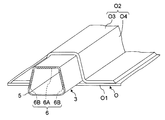
- FIG. 2 is a perspective view showing a structure at an end of the reinforced bladder bag shown in FIG.
- FIG. 6 is a cross-sectional view showing an example of a composite structure configured by attaching a corrugated stringer that can be formed by using the reinforced bladder bag shown in FIG. 1 as a core jig to a panel.
- FIG. 7 is a flow chart showing a first example of a method of forming a composite structure using the forming jig unit shown in FIG. 1.
- FIG. 7 is a flow chart showing a second example of a method of forming a composite structure using the forming jig unit shown in FIG. 1.
- the cross section which shows the structure of the reinforcement-added bladder bag which is a composite material shaping jig concerning a 3rd embodiment of the present invention.
- the cross section which shows the structure of the reinforcement-added bladder bag which is a composite material shaping jig concerning a 4th embodiment of the present invention.
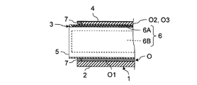
- FIG. 1 is a cross-sectional view showing the structure of a forming jig unit including a reinforced bladder bag which is a composite forming jig according to a first embodiment of the present invention.
- the forming jig unit 1 is a jig for forming a hollow composite material structure O having a two-dimensional closed curved surface. That is, the forming jig unit 1 is a laminate of the prepreg before curing in which the sheet-like fiber bundle is impregnated with the thermosetting resin, shaping of the laminated prepreg, and curing for heating and curing the laminate of the prepreg. It is a tool.
- thermosetting resin may be impregnated after laminating the sheet-like fibers.
- sheet-like fibers are laminated using the forming jig unit 1 in place of the sheet-like prepreg.
- the method of molding the composite material in which the resin is impregnated after laminating the fibers is called the RTM method as described above.
- RTM methods a method of impregnating fibers with a resin under vacuum pressure is called VaRTM (Vacuum assisted Resin Transfer Molding) method.
- the forming jig unit 1 can also be used for forming a composite material by the hybrid forming method using the lamination of the prepreg and the RTM method in combination.
- the hybrid molding method is a molding method of a composite material in which sheet-like fibers are laminated on a laminate of prepregs, and the laminated sheet-like fibers are impregnated with a resin and then heat-cured. Therefore, when the forming jig unit 1 is used for forming the composite material by the hybrid forming method, both the sheet-like prepreg and the sheet-like fiber are laminated.
- Arbitrary methods can be adopted as a method of heat-hardening a composite material.
- a typical heat curing method of the composite material there is a method in which the composite material before curing is carried into an autoclave forming apparatus, vacuum drawing is performed, and heat curing is performed under pressure.
- various de-autoclave (OoA: Out of autoclave) forming methods for forming a composite without using an autoclave forming apparatus are known.
- a method of heat curing a composite material in an oven is known. Therefore, the forming jig unit 1 in which the composite material before curing and after shaping is set can be carried into the desired equipment according to the heat curing method of the composite material.
- the composite material which reinforced resin with carbon fibers and glass fibers such as CFRP and GFRP
- CFRP and GFRP is typical.
- the composite material structure O having a hollow structure as illustrated in FIG. 1, the composite material structure O in which the hat-shaped elongated structure O2 is formed on the panel O1 is exemplified.
- the composite structure O having such a structure is mainly used as a wing structure or a fuselage structure of an aircraft.
- a reinforcing member having a long structure such as a rib or a stringer may be mentioned.
- lamination of sheet-like prepregs or sheet-like fibers for reinforcing member and panel O1, shaping of uncured resin for reinforcing member and panel O1, and reinforcing member and panel O1 can be co-cured to simultaneously heat and cure. That is, after assembling the reinforcing member and the panel O1 in an uncured state, bagging can be performed and heat curing can be performed simultaneously.
- the forming jig unit 1 is constituted by the forming die 2, the reinforced bladder bag 3 and the bagging film 4.
- the mold 2 is a rigid mold that supports the OML side of the panel O1.
- the surface on the OML side of the panel O1 is not limited to a flat surface and may be a curved surface with a small curvature. Therefore, the surface of the mold 2 has a substantially flat shape that matches the surface on the OML side of the panel O1 after molding.
- the mold 2 is a sheet-like prepreg or a laminate of fibers for the panel O1, a shaping on the OML side of the uncured resin for the panel O1, and a support with shape retention from the OML side at the time of heat curing of the panel O1.
- Used for The forming jig unit 1 is a jig unit that supports the OML side of the panel O1 with the forming die 2 and can be said to be a jig unit for the OML jig method.
- the reinforced bladder bag 3 is a partial inflatable mandrel that guides air to the inside and is used as a core jig. That is, the reinforced bladder bag 3 is used by being installed inside the composite structure O having a hollow structure. Therefore, the reinforced bladder bag 3 has a shape that fits inside the composite structure O having a hollow structure in the unfolded state.
- the reinforced bladder bag 3 includes a flexible tubular body 5 and at least one rigid plate embedded entirely in the tubular body 5 to partially reinforce the strength of the tubular body 5. Composed of six bodies. In the example shown in FIG. 1, three plate members 6 are inserted into the cylindrical member 5 in different directions with gaps in the direction perpendicular to the longitudinal direction of the cylindrical member 5.
- the tubular body 5 is made of the same material as the conventional bladder bag.
- the cylindrical body 5 can be made of an elastomer.
- the elastomer is a polymeric material having rubbery elasticity.
- the plate-like body 6 can be made of a composite material such as a metal or CFRP having sufficient mechanical strength to function as a rigid body.
- the plate-like body 6 is made of a composite material, it is possible to reduce the increase in weight of the reinforced bladder bag 3 accompanying the provision of the plate-like body 6 while securing the strength necessary for the plate-like body 6.
- the cylindrical body 5 in which the plate-like body 6 is embedded can be manufactured by arranging the plate-like body 6 at an appropriate position, and vulcanizing and molding an elastomer.
- the plurality of plate-like bodies 6 When a plurality of plate-like bodies 6 are embedded in the cylindrical body 5, the plurality of plate-like bodies 6 can be disposed with a gap in a direction perpendicular to the longitudinal direction of the cylindrical body 5. Thereby, while partial deformation of the cylindrical body 5 on the cross section of the cylindrical body 5 becomes possible, the deformation of the cylindrical body 5 on a plane parallel to the longitudinal direction of the cylindrical body 5 is suppressed. be able to. In other words, while the shape of the cross section of the cylindrical body 5 is deformed in a limited manner, rigidity can be imparted to the cylindrical body 5 on a plane parallel to the longitudinal direction of the cylindrical body 5.
- the reinforced bladder bag 3 has a hat-shaped cross section. It arrange
- the elongated structure O2 having a hat-shaped cross section has a structure in which two flat plate-shaped webs O4 are closed by a flat plate-shaped cap O3. Therefore, in the case where a composite material structure O in which the cross section has a hat-shaped long structure O2 formed on the panel O1 is a forming target, the composite material structure O during curing is the inner side of the long structure O2. As illustrated in FIG. 1, the first plate-like body 6A and the two second plate-like bodies 6B can be embedded in the inside of the cylindrical body 5 so as to support from the above.
- the first plate-like member 6A is a plate-like member 6 for reinforcing the strength of the portion of the tubular member 5 supporting the cap O3 of the long structure O2 from the inside.
- the two second plate-like members 6B are plate-like members 6 for respectively reinforcing the strength in the portion of the cylindrical member 5 which respectively supports the web O4 at two locations of the long structure O2 from the inside. It is. Therefore, the first plate-like body 6A is disposed at a position corresponding to the upper bottom of the R-chamfered isosceles trapezoid.
- the two second plate-like members 6B are respectively disposed at positions corresponding to the two legs of an isosceles trapezoidal R-chamfered trapezoid.
- the plate-like body 6 is not provided on the portion of the cylindrical body 5 fitted from the inside to the R-chamfer of the long structure O2 and the panel O1 side of the cylindrical body 5. That is, the portion of the reinforced bladder bag 3 supporting the R-chamfering of the long structure O2 from the inside and the portion of the reinforced bladder bag 3 on the panel O1 side are not reinforced by the plate-like body 6 and are composed of only the elastomer. .
- the reinforced bladder bag 3 can be deformed according to the deformation at the time of heat curing of the long structure O2.
- the reinforced bladder bag 3 since the plate-like body 6 is not inserted into the portion on the panel O1 side, after the heating and curing of the composite structure O, the reinforced bladder bag 3 may be bent inward to be easily pulled out from the inside of the long structure O2. It is possible.
- the shape of the long structure O2 can be held before and after heat curing. That is, the fibers impregnated with the uncured resin can be shaped into the shape of the long structure O2 by the reinforcing bladder bag 3 reinforced with the plate-like body 6 without using a rigid molding die. Furthermore, the shaped uncured resin can then be heat cured while maintaining its shape.
- the bagging film 4 is a film for performing bagging before the heat curing of the composite structure O.
- the bagging film 4 is attached to the mold 2 and the cylindrical body 5 of the reinforced bladder bag 3 with a sealant 7.
- the area covered by the bagging film 4 is depressurized by a vacuum device 8 equipped with a vacuum pump.
- FIG. 2 is a perspective view showing the structure at the end of the reinforced bladder bag 3 shown in FIG.
- the length of the reinforced bladder bag 3 is determined to be longer than the length of the long structure O2. Also, the length of the reinforced bladder bag 3 is determined so as to project beyond the edge of the panel O1. This is to allow the bagging film 4 to be attached to the reinforced bladder bag 3 with the sealant 7 outside the uncured resin while opening the inside of the reinforced bladder bag 3 to the outside.
- the side surface of the reinforced bladder bag 3 does not necessarily have to be closed. This is because it is desirable to introduce heating air to the inside of the reinforced bladder bag 3 at the time of heat curing of the composite structure O. In addition, at the time of positioning of the reinforced bladder bag 3, it is desirable to insert the rigid positioning member 9 inside the reinforced bladder bag 3 in order to prevent deflection in the longitudinal direction of the reinforced bladder bag 3.
- the side surface of the reinforced bladder bag 3 may be closed, and a through hole for introducing air may be provided.
- the side surface of the reinforced bladder bag 3 may be closed by an openable lid.
- FIG. 3 is a longitudinal sectional view for explaining the sealing method at the end of the reinforced bladder bag 3 shown in FIG.
- the portion of the bagging film 4 covering the long structure O 2 before curing can be attached to the reinforced bladder bag 3 with the sealant 7.
- the portion of the bagging film 4 covering the panel O1 before curing can be attached to the mold 2 with the sealant 7.
- the gap formed between the reinforced bladder bag 3 and the mold 2 and corresponding to the thickness of the panel O1 can also be closed with the sealant 7.
- region covered with the bagging film 4 can be sealed and vacuum suction can be performed by the vacuum apparatus 8.
- FIG. 1 shows an example in which the composite material structure O in which the transverse cross section has a hat-shaped long structure O2 formed on the panel O1 is a forming object, but it is a two-dimensional closed surface.
- the reinforced bladder bag 3 can be used for forming processes intended for various composite structures having a hollow structure to be formed.
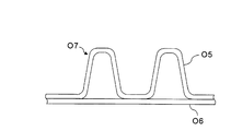
- FIG. 4 is a cross-sectional view showing an example of a composite structure O7 configured by attaching to the panel O6 a corrugated stringer O5 which can be formed by using the reinforced bladder bag 3 shown in FIG. 1 as a core jig.
- FIG. 4 is a cross-sectional view showing an example of a composite structure O7 configured by attaching to the panel O6 a corrugated stringer O5 which can be formed by using the reinforced bladder bag 3 shown in FIG. 1 as a core jig.
- FIG. 4 is a cross-sectional view showing an example of a composite structure O7 configured by attaching to the panel O6 a corrugated stringer O5 which can be formed by using the reinforced bladder bag 3 shown in FIG. 1 as a core jig.
- FIG. 4 is a cross-sectional view showing an example of a composite structure O7 configured by attaching to the panel O6 a corrugated stringer O5 which can be formed by using the reinforced bladder bag 3 shown in FIG. 1 as
- a composite material structure O7 configured by attaching to a panel O6 a corrugated stringer O5 having a corrugated structure in which a plurality of reinforcing members whose cross sections are hat-shaped are connected is a plurality of reinforced bladder bags 3 It can be molded using That is, the composite material structure O7 can be heat-hardened in a state in which the reinforcement-included bladder bag 3 is placed in a plurality of spaces surrounded by the closed curved surface formed between the corrugated stringer O5 and the panel O6.
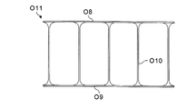
- FIG. 5 shows a composite structure having a structure in which an upper panel O8 and a lower panel O9 can be formed by using the reinforced bladder bag 3 shown in FIG. 1 as a core jig by a plurality of stringers O10. It is a cross-sectional view which shows the example of the body O11.
- a composite material structure O11 having a structure in which an upper panel O8 and a lower panel O9 are connected by a plurality of stringers O10 as shown in FIG. 5 can be formed using a plurality of reinforced bladder bags 3. That is, the composite structure O11 is heat-cured in a state in which the reinforcement-containing bladder 3 is placed in the space surrounded by the closed surface, which is formed between the upper panel O8, the lower panel O9 and two adjacent stringers O10. can do.
- the shape of the cross section of the stringer O10 is not limited to an I shape, but is arbitrary.
- FIG. 6 is a flowchart showing a first example of a method of forming the composite material structure O using the forming jig unit 1 shown in FIG.
- step S1 a sheet-like prepreg P1 for the panel O1 is stacked on the mold 2.
- step S2 a sheet-like prepreg P2 for the long structure O2, which is a reinforcing member of the panel O1, is stacked on the reinforcing bladder bag 3.
- the prepreg P1 for the panel O1 and the prepreg P2 for the long structure O2 can be respectively laminated on the mold 2 and the reinforced bladder bag 3 by an automatic laminating apparatus. Alternatively, the operator may manually laminate the prepreg P1 for the panel O1 and the prepreg P2 for the long structure O2.
- the reinforced bladder bag 3 on which the prepreg P2 for the long structure O2 is laminated is partially reinforced by the plate-like body 6.
- the strength at the portion of the cylindrical body 5 supporting the cap O3 of the long structure O2 from the inside is reinforced by the first plate-like body 6A.
- the strength in the part of the cylindrical body 5 which respectively supports the web O4 of two places of the elongate structure O2 from the inside is reinforced by the 2nd 2nd plate-like body 6B.
- a laminate of the prepreg P2 for the long structure O2 may be shaped by using a rigid jig such as the positioning member 9 in combination.
- step S3 the reinforced bladder bag 3 in which the sheet-like prepreg P2 for the long structure O2 is laminated is placed on the sheet-like prepreg P1 for the laminated panel O1.
- the sheet-like prepreg P2 for the long structure O2 may be laminated on the reinforced bladder bag 3 after the reinforced bladder bag 3 is placed on the sheet-like prepreg P1 for the panel O1. Good. However, if the prepreg P1 for the panel O1 and the prepreg P2 for the long structure O2 are separately laminated and then assembled, the working time is shortened.
- the prepreg P2 for the long structure O2 is placed on a rigid mold for the long structure O2.
- the laminated body of the prepreg P2 for the long structure O2 may be placed on the reinforced bladder bag 3 after laminating and shaping.
- the preform (uncured composite material) for the long structure O2 may be shaped not by the reinforced bladder bag 3 but by another rigid jig. In this case, since the preform for the long structure O2 is shaped by a rigid jig, a high quality preform can be manufactured.
- the reinforced bladder bag 3 has an elongated structure and is flexible. Therefore, when the length of the reinforced bladder bag 3 is long, bending occurs when the reinforced bladder bag 3 is transported by a hoist even if it is reinforced by the plate-like body 6. In particular, it is difficult to transport and position the reinforced bladder bag 3 in a state in which the prepreg P2 for the long structure O2 is stacked while maintaining the shape of the laminate of the prepreg P2 for the long structure O2.
- the positioning member 9 may be inserted in advance into the inside of the reinforced bladder bag 3 before laminating the prepreg P2 for the long structure O2, or the reinforced bladder bag after laminating the prepreg P2 for the long structure O2. You may insert in the inside of 3.
- the rigidity of the reinforced bladder bag 3 at the time of the lamination of the prepreg P2 for the long structure O2. Can be secured further. That is, the rigidity of the reinforced bladder bag 3 can be maintained to the same degree as that of the rigid body. For this reason, in the case of forming a preform for the long structure O2 using the reinforcement-containing bladder 3, it is similar to the case where the preform for the long structure O2 is formed using a rigid mold. It is possible to produce a preform for the long structure O2 with quality.
- the shape of the positioning member 9 is similar to the shape of the space formed inside the reinforced bladder bag 3 so as to appropriately restrain the deflection of the reinforced bladder bag 3 and to be able to be pulled out from the reinforced bladder bag 3. Is appropriate. Therefore, the structure of the positioning member 9 is a long structure, and is an isosceles trapezoid in which four corners are rounded. In addition, it is appropriate for the size of the outer surface of the positioning member 9 to provide a clearance for the size of the inner surface of the reinforcing bladder bag 3 so that the positioning member 9 can be easily pulled out from the reinforced bladder bag 3 .
- bagging is performed in step S4. Specifically, the sheet-like prepreg P1 for the laminated panel O1 and the sheet-like prepreg P2 for the long structure O2 are covered with the bagging film 4. However, the laminated body of the prepreg P1 for the panel O1 and the laminated body of the prepreg P2 for the long structure O2 are covered with the bagging film 4 so that the inside of the reinforced bladder bag 3 is opened to the outside without being sealed.
- the vacuum device 8 is driven to discharge the air from the area covered with the bagging film 4. That is, the area covered by the bagging film 4 is depressurized by the vacuum device 8. As a result, a differential pressure between the atmospheric pressure applied from the outside of the bagging film 4 and the vacuum pressure in the area covered by the bagging film 4 is applied to the area covered with the bagging film 4.
- the pressure is atmospheric pressure. Therefore, the atmospheric pressure loaded from the outside of the reinforced bladder bag 3 through the laminate of the bagging film 4 and the prepreg P2 for the long structure O2 is loaded from the inside of the reinforced bladder bag 3 to the reinforced bladder bag 3 It will be balanced with the atmospheric pressure. Moreover, the flat portions of the reinforced bladder bag 3 fitted to the cap O3 and the web O4 of the long structure O2 before curing are reinforced by the first plate 6A and the second plate 6B, respectively. . As a result, the shape of the laminate of the prepreg P2 for the long structure O2 can be held by the reinforced bladder bag 3 according to the shape of the long structure O2 after molding, before and after bagging.
- step S5 the laminate of the prepreg P1 for the panel O1 and the laminate of the prepreg P2 for the long structure O2 after bagging, that is, an uncured thermosetting resin reinforced with sheet-like fibers It is heat cured.
- the laminated body of the prepreg P1 for the panel O1 and the laminated body of the prepreg P2 for the long structure O2 after bagging are carried into an oven or an autoclave apparatus together with the mold 2 and the reinforced bladder bag 3.
- the composite which attached the elongate structure O2 to the panel O1 by heating the laminated body of the prepreg P1 for panel O1 under pressure, and the laminated body of the prepreg P2 for elongate structures O2 under pressure with an oven or an autoclave apparatus
- the material structure O is co-cure molded.
- the composite structure O undergoes a slight deformation associated with the heat curing.
- the reinforced bladder bag 3 is reinforced by the first plate 6A and the second plate 6B. It has flexibility except for flat portions on the cap O3 side and the web O4 side. Therefore, even if the composite material structure O including the long structure O2 is deformed due to heat curing, the reinforced bladder bag 3 can be fitted on the inner surface side of the long structure O2. Thereby, the composite material structure O which attached the cross-section long structure O2 of a hat type to the panel O1 can be manufactured with favorable quality.
- step S6 the composite structure O after the heat curing is carried out of the oven or the autoclave together with the mold 2 and the reinforced bladder bag 3. Then, the composite material structure O after the heating and curing is taken out from the forming jig unit 1 including the reinforced bladder bag 3.
- the reinforced bladder 3 is removed from the composite structure O after heat curing.
- the plate-like body 6 is not embedded in the side of the panel O1 of the tubular body 5 constituting the reinforcing bladder bag 3, the reinforcing bladder bag 3 can be easily deformed inward. For this reason, it is possible to easily pull out the reinforced bladder bag 3 from the inside of the long structure O2 after heat curing.
- the positioning member 9 for suppressing the bending of the reinforcing bag 3 can be pulled out of the reinforcing bag 3 after bagging or after heat curing.
- the composite forming method shown in FIG. 6 is a method of manufacturing a composite structure O having a hollow structure by laminating and heat curing a prepreg P1 for the panel O1 and a prepreg P2 for the long structure O2.
- the composite structure O having a hollow structure can also be manufactured by the VaRTM method.
- FIG. 7 is a flowchart showing a second example of a method of forming the composite material structure O using the forming jig unit 1 shown in FIG.
- step S10 the sheet-like fiber F1 for the panel O1 is laminated on the mold 2.
- step S11 the sheet-like fiber F2 for the long structure O2, which is a reinforcing member of the panel O1, is stacked on the reinforcing bladder bag 3.
- the fiber F1 for the panel O1 and the fiber F2 for the long structure O2 can be respectively laminated on the mold 2 and the reinforced bladder bag 3 by an automatic laminating apparatus.
- the worker may manually laminate the fiber F1 for the panel O1 and the fiber F2 for the long structure O2.
- it since there is no adhesive force between sheet-like fibers F2, it can be attached with a binder as needed.
- step S12 the reinforced bladder bag 3 in which the sheet-like fibers F2 for the long structure O2 are laminated is placed on the sheet-like fibers F1 for the laminated panel O1.
- the sheet fiber F2 for the long structure O2 is laminated on the reinforcing bladder bag 3 as well. Good. However, if the fiber F1 for the panel O1 and the fiber F2 for the long structure O2 are separately laminated and then assembled, the working time is shortened.
- the reinforced bladder sheet 3 is inserted in a state in which the rigid positioning member 9 for suppressing the deflection of the reinforced bladder bag 3 is inserted into the reinforced bladder bag 3. It is desirable from the viewpoint of placing the reinforced bladder bag 3 in a more accurate position, to be placed on the flat fiber.
- step S13 bagging is performed in step S13. Specifically, the sheet-like fibers F1 for the laminated panel O1 and the sheet-like fibers F2 for the long structure O2 are covered with the bagging film 4. However, the laminated body of the fiber F1 for the panel O1 and the laminated body of the fiber F2 for the long structure O2 are covered with the bagging film 4 so that the inside of the reinforced bladder bag 3 is opened to the outside without being sealed.
- the vacuum device 8 is driven to discharge the air from the area covered with the bagging film 4. That is, the area covered by the bagging film 4 is depressurized by the vacuum device 8. As a result, a differential pressure between the atmospheric pressure applied from the outside of the bagging film 4 and the vacuum pressure in the area covered by the bagging film 4 is applied to the area covered with the bagging film 4.
- step S14 an uncured thermosetting resin is injected into the area covered by the bagging film 4. That is, the uncured thermosetting resin is supplied from the resin storage tank 10 into the area covered with the bagging film 4. Thereby, the uncured thermosetting resin can be impregnated into the fiber F1 for the panel O1 and the fiber F2 for the long structure O2.
- the uncured thermosetting resin can be injected not only from the position where the fiber F1 for the panel O1 is laminated, but also from the position where the sheet-like fiber F2 for the long structure O2 is laminated. Then, the uncured resin can be quickly impregnated into the sheet-like fiber F2 for the long structure O2. As a result, the time required to impregnate the resin can be shortened.
- FIG. 7 shows an example in which fibers are supplied from both the position where the fiber F1 for the panel O1 is laminated and the position where the fiber F2 for the long structure O2 is laminated.
- the inside of the reinforced bladder bag 3 is not sealed by the bagging film 4 and thus the atmospheric pressure is obtained. Therefore, the atmospheric pressure loaded from the outside of the reinforced bladder bag 3 through the laminate of the bagging film 4 and the fiber F2 impregnated with the resin for the long structure O2 is the reinforced bladder bag from the inside of the reinforced bladder bag 3 It will be balanced with the atmospheric pressure loaded on 3. Moreover, the flat portions of the reinforced bladder bag 3 fitted to the cap O3 and the web O4 of the long structure O2 before curing are reinforced by the first plate 6A and the second plate 6B, respectively. .
- the shape of the laminate of fibers F2 impregnated with the resin for the long structure O2 can be shaped according to the shape of the long structure O2 after the molding. Moreover, the shape after shaping of the laminate of the fibers F2 impregnated with the resin for the long structure O2 can be held by the reinforced bladder bag 3.
- step S15 a laminate of fibers F1 impregnated with resin for panel O1 after bagging and injection of resin and a laminate of fibers F2 impregnated with resin for long structure O2, ie, sheet-like
- the fiber-reinforced uncured thermosetting resin is heat-cured.
- a laminate of fibers F1 impregnated with a resin for panel O1 and a laminate of fibers F2 impregnated with a resin for long structure O2 are the mold 2 and a mold. It is carried into the oven or the autoclave together with the reinforced bladder bag 3. Then, the laminate of the fibers F1 impregnated with the resin for the panel O1 under pressure and the laminate of the fibers F2 impregnated with the resin for the long structure O2 are heated by an oven or an autoclave apparatus, thereby obtaining a long film.
- the composite structure O having the structure O2 attached to the panel O1 is co-cured. Thereby, the composite material structure O which attached the cross-section long structure O2 of a hat type to the panel O1 can be manufactured with favorable quality.
- step S16 the composite structure O after heat curing is carried out of the oven or the autoclave together with the mold 2 and the reinforced bladder bag 3. Then, the composite material structure O after the heating and curing is taken out from the forming jig unit 1 including the reinforced bladder bag 3. At this time, as in step S6 of FIG. 6, the reinforcing bladder is inserted into the long structure O2 by deforming the side of the panel O1 not reinforced with the plate-like member 6 inward. It can be easily pulled out of the
- the hat-shaped elongated structure O2 is attached to the panel O1 by the hybrid molding method using the lamination of the prepreg and the VaRTM method in combination.
- the composite structure O can also be manufactured.
- a laminate of fibers F1 impregnated with a resin is manufactured by laminating a prepreg P1
- the elongated structure O2 is a fiber F2 impregnated with a resin by the VaRTM method.
- Laminates can be made.
- the composite structure having a desired hollow structure is manufactured not only by the composite structure O having the hat-shaped elongated structure O2 attached to the panel O1 but by the above-described composite forming method. Is possible.
- the composite material forming method as described above is such that a composite material structure having a hollow structure is formed by using the reinforced bladder bag 3 partially reinforced by the rigid plate 6 as a core jig. . That is, the reinforced bladder bag 3 retains the extensibility necessary for molding while providing the bladder bag with a shape retaining function.
- the structure of the jig is simplified as compared with the conventional one while securing the freedom of design when forming the composite material structure having the hollow structure.
- FIG. 8 is a view showing a method of forming a composite according to a conventional OML jig method in which a composite structure having a hat-shaped cross section is formed using a mandrel as a core jig.
- the OML side of the panel O1 is selected as one of the conventional composite material forming methods for manufacturing a composite material structure O in which the cross section has a hat-shaped long structure O2 attached to the panel O1.
- the shape of the composite structure O is limited to a shape that allows the mandrel 21 to be pulled out.
- the handling including the transfer of the mandrel 21 requires labor.
- the reinforced bladder bag 3 can be deformed, it can be easily pulled out from the inside of the long structure O2 after heat curing. For this reason, it is possible to secure the freedom of design of the composite structure having a hollow structure as well as the composite structure O in which the elongated cross section O2 is attached to the panel O1 in cross section. Moreover, since the reinforced bladder bag 3 is hollow, it is lightweight, and handling including transport is easy.
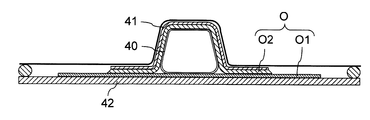
- FIG. 9 is a view showing a method for forming a composite material according to a conventional IML jig method, in which a composite material structure having a hat-shaped cross section is formed using upper and lower molds and a normal bladder bag.
- An IML of panel O1 as shown in FIG. 9 is one of the other conventional composite forming methods for fabricating a composite structure O in which a cross section has a hat-shaped elongated structure O2 attached to the panel O1.
- the composite material structure O is manufactured by the OML jig system using the reinforcement-included bladder bag 3, a mold having a complicated structure becomes unnecessary.
- the panel O1 can be stably supported by the rigid mold 2.
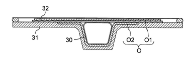
- FIG. 10 is a view showing a method of forming a composite according to a conventional OML jig method in which a composite structure having a hat-shaped cross section is formed using upper and lower molds and a normal bladder bag.
- FIG. 10 As shown in FIG. 10, as one of the conventional composite forming methods for manufacturing a composite structure O in which the cross section has a hat-shaped elongated structure O2 attached to the panel O1, as shown in FIG.
- the OML side is downward, and the bladder bag 40 without reinforcement is inserted inside the long structure O2 before curing, while the entire composite structure O before curing is called the IML side mold 41 called a cowl plate, the OML side There is a method of supporting the mold 42 from two directions.
- the cowl plate which is the IML side molding die 41 can be made unnecessary. That is, even if the cowl plate is not used, the reinforced bladder bag 3 is deformed into a cylindrical shape during heat curing of the composite structure O, or the cap O3 or the web O4 is dented or distorted due to the influence of gravity. Can be avoided.
- the jig conventionally placed on the atmosphere side can be omitted. For this reason, the labor and time required for placing, removing and cleaning the jig can be reduced.
- the weight of the composite structure O including the jig can be reduced. For this reason, not only conveyance becomes easy, but the volume of the object to be heated can be reduced. As a result, the time and energy required for the heat curing of the composite structure O can be reduced.
- the rigid body mold is not installed on the atmosphere side. Therefore, the pressure corresponding to the atmospheric pressure can be uniformly applied to the composite structure O during heat curing. As a result, the composite structure O can be manufactured with good quality.
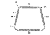
- FIG. 11 is a cross-sectional view showing the structure of a reinforced bladder bag which is a composite molding jig according to a second embodiment of the present invention.
- the point at which the third plate-like body 6C is embedded in the panel O1 side of the cylindrical body 5 constituting the reinforced bladder bag 3A is the first It differs from the forming jig unit 1 in the embodiment.
- the other configuration and operation of the forming jig unit 1A in the second embodiment are not substantially different from those of the forming jig unit 1 in the first embodiment, and therefore the same configuration or the corresponding configuration have the same reference numerals. The explanation is omitted.
- the first plate-like body 6A and the elongated structure on the cap O3 side of the elongated structure O2 whose cross-sectional shape is a hat type In addition to the two second plate-like members 6B on the web O4 side of the object O2, the third plate-like member 6C on the panel O1 side can be embedded. Then, the reinforced bladder bag 3A can be reinforced by the third plate-like body 6C also on the panel O1 side.
- the reinforced bladder bag 3A When the reinforced bladder bag 3A is reinforced with the third plate-like member 6C divided in this way, the reinforcement with the third bladder 6C partially reinforces the strength of the reinforced bladder bag 3A on the panel O1 side. It is possible to easily fold the bladder bag 3A on the panel O1 side. Therefore, the reinforced bladder bag 3A can be easily pulled out from the composite structure O after heat curing.
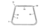
- FIG. 12 is a cross-sectional view showing the structure of a reinforced bladder bag which is a composite molding jig according to a third embodiment of the present invention.
- the point in which a part of the plate-like body 6 is embedded in the cylindrical body 5 constituting the reinforced bladder bag 3B is the forming according to the first embodiment. It differs from the jig unit 1.
- the other configuration and function of the forming jig unit 1B in the third embodiment are not substantially different from those of the forming jig unit 1 in the first embodiment, and only the reinforced bladder bag 3B is illustrated, and the same configuration or correspondence The same components are given the same reference numerals and the description thereof is omitted.
- the reinforced bladder bag 3 ⁇ / b> B can be configured by embedding only a part of the plate-like body 6 in the tubular body 5 without embedding the whole plate-like body 6 in the tubular body 5. Then, the plate-like body 6 can be replaced as needed. Therefore, for example, when the plate 6 is deformed or when using the plate 6 having different strength, the plate 6 can be easily replaced.
- the second embodiment instead of embedding the entire plate-like body 6 in the tubular body 5, a part of the plate-like body 6 can be embedded in the tubular body 5.
- FIG. 13 is a cross section showing the structure of a reinforced bladder bag which is a composite molding jig according to a fourth embodiment of the present invention.
- the forming in the first embodiment is that the plate 6 is attached to the inner surface of the cylindrical body 5 constituting the reinforced bladder bag 3C. It differs from the jig unit 1.
- the other configuration and operation of the forming jig unit 1C in the fourth embodiment are not substantially different from those of the forming jig unit 1 in the first embodiment, and only the reinforced bladder bag 3C is illustrated, and the same structure or corresponding The same components are given the same reference numerals and the description thereof is omitted.
- the reinforcing bladder is configured by sticking one surface of the plate 6 to the inner surface of the tube 5 with an adhesive without embedding the plate 6 in the tube 5. You can also. Then, not only can the plate-like body 6 be replaced as necessary, but it becomes possible to affix the plate-like body 6 to the existing bladder bag to produce the reinforced bladder bag 3C. Therefore, as in the third embodiment, for example, when the plate 6 is deformed or when the plate 6 having different strength is used, the plate 6 can be easily replaced or attached. it can. Of course, in the second embodiment, instead of embedding the plate-like body 6 in the tubular body 5, one surface of the plate-like body 6 may be attached to the inner surface of the tubular body 5.
Landscapes
- Engineering & Computer Science (AREA)
- Mechanical Engineering (AREA)
- Chemical & Material Sciences (AREA)
- Composite Materials (AREA)
- Architecture (AREA)
- Civil Engineering (AREA)
- Structural Engineering (AREA)
- Manufacturing & Machinery (AREA)
- Moulding By Coating Moulds (AREA)
- Casting Or Compression Moulding Of Plastics Or The Like (AREA)
- Moulds For Moulding Plastics Or The Like (AREA)
Priority Applications (5)
| Application Number | Priority Date | Filing Date | Title |
|---|---|---|---|
| EP18837979.6A EP3659774B1 (de) | 2017-07-25 | 2018-04-02 | Verbundstoffmaterialformgestell und verbundstoffmaterialformverfahren |
| CN201880047436.2A CN110891752B (zh) | 2017-07-25 | 2018-04-02 | 复合材料成形夹具及复合材料成形方法 |
| ES18837979T ES2954328T3 (es) | 2017-07-25 | 2018-04-02 | Plantilla de moldeo de materiales compuestos y método de moldeo de materiales compuestos |
| JP2019532368A JP6774571B2 (ja) | 2017-07-25 | 2018-04-02 | 複合材成形治具及び複合材成形方法 |
| US16/750,183 US11701797B2 (en) | 2017-07-25 | 2020-01-23 | Composite material molding jig and composite material molding method |
Applications Claiming Priority (2)
| Application Number | Priority Date | Filing Date | Title |
|---|---|---|---|
| JP2017143970 | 2017-07-25 | ||
| JP2017-143970 | 2017-07-25 |
Related Child Applications (1)
| Application Number | Title | Priority Date | Filing Date |
|---|---|---|---|
| US16/750,183 Continuation US11701797B2 (en) | 2017-07-25 | 2020-01-23 | Composite material molding jig and composite material molding method |
Publications (1)
| Publication Number | Publication Date |
|---|---|
| WO2019021537A1 true WO2019021537A1 (ja) | 2019-01-31 |
Family
ID=65041122
Family Applications (1)
| Application Number | Title | Priority Date | Filing Date |
|---|---|---|---|
| PCT/JP2018/014177 Ceased WO2019021537A1 (ja) | 2017-07-25 | 2018-04-02 | 複合材成形治具及び複合材成形方法 |
Country Status (6)
| Country | Link |
|---|---|
| US (1) | US11701797B2 (de) |
| EP (1) | EP3659774B1 (de) |
| JP (1) | JP6774571B2 (de) |
| CN (1) | CN110891752B (de) |
| ES (1) | ES2954328T3 (de) |
| WO (1) | WO2019021537A1 (de) |
Cited By (5)
| Publication number | Priority date | Publication date | Assignee | Title |
|---|---|---|---|---|
| CN111497280A (zh) * | 2020-04-26 | 2020-08-07 | 吉林联科特种石墨材料有限公司 | 一种真空压缩二次成型沥青基保温筒成型方法 |
| WO2021019569A1 (en) * | 2019-07-31 | 2021-02-04 | Gosakan Aravamudan | Expansion held prepeg composite |
| JP2022050329A (ja) * | 2020-09-17 | 2022-03-30 | ザ・ボーイング・カンパニー | 湾曲複合材ハットストリンガーの拘束成形 |
| CN114683575A (zh) * | 2022-03-18 | 2022-07-01 | 南京聚隆复合材料技术有限公司 | 一种碳纤维复合材料轨道清障装置的制备方法 |
| JP2023539417A (ja) * | 2020-07-27 | 2023-09-14 | レオナルド・エッセ・ピ・ア | 少なくとも1つのストリンガで補剛された複合材料において構造コンポーネントを製造するためのプロセス |
Families Citing this family (7)
| Publication number | Priority date | Publication date | Assignee | Title |
|---|---|---|---|---|
| CN113977984B (zh) * | 2021-10-15 | 2023-07-04 | 江西洪都航空工业集团有限责任公司 | 一种管状双曲面复合材料结构件的制备方法 |
| CN115056510B (zh) * | 2022-07-06 | 2024-02-13 | 航天海鹰(镇江)特种材料有限公司 | 一种利用双黄袋辅助热压罐成型螺旋桨叶片的方法 |
| US12472704B2 (en) * | 2022-09-12 | 2025-11-18 | Chang-Hung Tsai | Hot-pressing molding method for fiber thermosetting prepreg material |
| WO2024097922A1 (en) * | 2022-11-03 | 2024-05-10 | University Of Virginia Patent Foundation | Digital fabrication of complex surfaces through actuated modular pneumatics |
| GB202219112D0 (en) * | 2022-12-16 | 2023-02-01 | Short Brothers Plc | Apparatus and methods for forming composite parts |
| CN117287623A (zh) * | 2023-09-08 | 2023-12-26 | 浙江大学 | 用于低温绝热容器外壳的筒体、低温绝热容器及制造设备 |
| EP4659946A1 (de) * | 2024-06-04 | 2025-12-10 | AIRBUS Operations GmbH | Flexibles schlauchelement |
Citations (11)
| Publication number | Priority date | Publication date | Assignee | Title |
|---|---|---|---|---|
| JPH03268911A (ja) | 1990-03-20 | 1991-11-29 | Mitsubishi Heavy Ind Ltd | 複合材一体成形用形状保持装置 |
| JPH04223140A (ja) * | 1990-12-26 | 1992-08-13 | Fuji Heavy Ind Ltd | 複合材の成形方法 |
| JP2001150465A (ja) | 1999-11-30 | 2001-06-05 | Toyota Motor Corp | 中空成形物の製造方法および装置 |
| JP2003039566A (ja) | 2001-07-27 | 2003-02-13 | Fuji Heavy Ind Ltd | 補強パネルの製造方法 |
| JP2009542460A (ja) * | 2006-07-06 | 2009-12-03 | エアバス・オペレーションズ・ゲーエムベーハー | 折り畳み可能な成形コアを用いた複合ファイバ構成要素を作製する方法および上記成形コア |
| JP2010510111A (ja) | 2006-11-20 | 2010-04-02 | ザ・ボーイング・カンパニー | 熱膨張ツーリングコールを使用してハット型に強化された複合部品を形成する装置及び方法 |
| JP2011062846A (ja) | 2009-09-15 | 2011-03-31 | Kawasaki Heavy Ind Ltd | 横断面に肉厚部位を有する複合材料構造物製造用治具 |
| JP2011098527A (ja) * | 2009-11-06 | 2011-05-19 | Kawasaki Heavy Ind Ltd | 複合材料構造物製造用治具 |
| JP2011235635A (ja) * | 2010-05-11 | 2011-11-24 | Boeing Co:The | 強化フルオロエラストマーブラダを用いた折り畳み式マンドレル |
| JP2013078937A (ja) | 2011-08-26 | 2013-05-02 | Boeing Co:The | 一体補強された再使用可能な真空バッグ及びその製造方法 |
| JP2015142993A (ja) * | 2014-01-31 | 2015-08-06 | 三菱重工業株式会社 | Frp成形治具及びfrp構造体の成形方法 |
Family Cites Families (84)
| Publication number | Priority date | Publication date | Assignee | Title |
|---|---|---|---|---|
| US3187069A (en) * | 1962-09-28 | 1965-06-01 | Kay Mfg Corp | Making foamed articles |
| US3651180A (en) * | 1968-08-08 | 1972-03-21 | Foam Forms Inc | Method of molding expandable polystyrene particles using an inflatable core in the mold cavity |
| US3979249A (en) * | 1971-06-10 | 1976-09-07 | Dunlop Limited | Tire building apparatus |
| US4062917A (en) * | 1976-11-05 | 1977-12-13 | Burlington Industries, Inc. | Method of molding resin-impregnated fabric layer using release sheet and absorbent sheet inside evacuated bag |
| US4323218A (en) * | 1980-08-22 | 1982-04-06 | E & E Kaye Limited | Inflatable core for use in forming a thermal break in a metal frame for a door or window |
| GB2172238B (en) * | 1985-03-12 | 1989-12-28 | Diversified Prod | Racquets |
| US4877469A (en) * | 1987-03-18 | 1989-10-31 | The Armstrong Rubber Company | Reinforced tire curing bladder and method for using same |
| US4963215A (en) * | 1987-12-07 | 1990-10-16 | The Boeing Company | Method for debulking precured thermoplastic composite laminae |
| US5062781A (en) * | 1988-08-10 | 1991-11-05 | Firelli Armstrong Tire Corporation | Reinforced tire curing bladder |
| US4923541A (en) * | 1988-10-22 | 1990-05-08 | George Burger | Method for making composite reinforced tubes |
| US5087193A (en) * | 1990-08-09 | 1992-02-11 | Herbert Jr Kenneth H | Apparatus for forming a composite article |
| US5266249A (en) * | 1992-01-02 | 1993-11-30 | Fusion Composites, Inc. | Method of forming a fiber reinforced plastic structure |
| US5242523A (en) * | 1992-05-14 | 1993-09-07 | The Boeing Company | Caul and method for bonding and curing intricate composite structures |
| JPH07223271A (ja) * | 1993-12-16 | 1995-08-22 | Toray Ind Inc | 曲がり管とその製造方法および装置 |
| US5904972A (en) * | 1995-06-07 | 1999-05-18 | Tpi Technology Inc. | Large composite core structures formed by vacuum assisted resin transfer molding |
| US6217000B1 (en) * | 1996-10-25 | 2001-04-17 | The Boeing Company | Composite fabrication method and tooling to improve part consolidation |
| US6458309B1 (en) * | 1998-06-01 | 2002-10-01 | Rohr, Inc. | Method for fabricating an advanced composite aerostructure article having an integral co-cured fly away hollow mandrel |
| CA2287561C (en) * | 1998-10-26 | 2007-08-28 | Faroex Ltd. | Structural panel for bridging between spaced support |
| US6620369B1 (en) * | 2000-02-09 | 2003-09-16 | Northrop Grumman Corporation | Net molding of resin composite parts |
| JP4448242B2 (ja) * | 2000-09-05 | 2010-04-07 | 本田技研工業株式会社 | スティフンドパネル用成形補助治具 |
| US6808154B2 (en) * | 2001-03-22 | 2004-10-26 | Column & Post., Inc. | Mold and molding process |
| US7081218B2 (en) * | 2001-08-07 | 2006-07-25 | Toray Industries, Inc. | Method for producing upsized FRP member |
| US6896841B2 (en) * | 2003-03-20 | 2005-05-24 | The Boeing Company | Molding process and apparatus for producing unified composite structures |
| US7625618B1 (en) * | 2003-05-15 | 2009-12-01 | Rohr, Inc. | Advanced composite aerostructure article having a braided co-cured fly away hollow mandrel and method for fabrication |
| US7228611B2 (en) * | 2003-11-18 | 2007-06-12 | The Boeing Company | Method of transferring large uncured composite laminates |
| ES2315580T3 (es) * | 2004-02-13 | 2009-04-01 | Saab Ab | Procedimiento para la fabricacion de un articulo de material compuesto. |
| US7527222B2 (en) * | 2004-04-06 | 2009-05-05 | The Boeing Company | Composite barrel sections for aircraft fuselages and other structures, and methods and systems for manufacturing such barrel sections |
| US7293737B2 (en) * | 2004-04-20 | 2007-11-13 | The Boeing Company | Co-cured stringers and associated mandrel and fabrication method |
| ATE493253T1 (de) * | 2005-03-30 | 2011-01-15 | Eads Constr Aeronauticas Sa | Verfahren zur herstellung einer monolithischen lüfterhaube |
| US20070080481A1 (en) * | 2005-10-12 | 2007-04-12 | The Boeing Company | Apparatus and methods for fabrication of composite components |
| US7824171B2 (en) * | 2005-10-31 | 2010-11-02 | The Boeing Company | Corner-consolidating inflatable apparatus and method for manufacturing composite structures |
| ES2341114T3 (es) * | 2005-12-20 | 2010-06-15 | Saab Ab | Procedimiento de fabricacion de un elemento estructural alargado con figurado para la rigidizacion de una estructura de panel y un procedimiento de fabricacion de una estructura de panel rigida integrada con al menos un elemento de rigidizacion alargado de rigidizacion alargado. |
| FR2898539B1 (fr) * | 2006-03-20 | 2008-05-23 | Eads Ccr Groupement D Interet | Procede de realisation de panneaux raidis en materiau composite et panneaux ainsi realises |
| GB0613872D0 (en) * | 2006-07-12 | 2006-08-23 | Airbus Uk Ltd | Method of manufacturing composite part |
| US8691037B2 (en) * | 2006-12-14 | 2014-04-08 | The Boeing Company | Method for minimizing fiber distortion during fabrication of one-piece composite barrel section |
| EP1946915A1 (de) * | 2007-01-22 | 2008-07-23 | Saab Ab | Verfahren und Vorrichtung zur Herstellung eines Profilelements |
| US7861969B2 (en) * | 2007-05-24 | 2011-01-04 | The Boeing Company | Shaped composite stringers and methods of making |
| BRPI0721694A2 (pt) * | 2007-05-28 | 2013-02-13 | Airbus Operations Sl | procedimento e ferramenta para a fabricaÇço de estruturas reforÇadas a partir de materiais compostos |
| US7879276B2 (en) * | 2007-11-08 | 2011-02-01 | The Boeing Company | Foam stiffened hollow composite stringer |
| DE102007060029A1 (de) * | 2007-12-13 | 2009-06-18 | Airbus Deutschland Gmbh | Verfahren und Vorrichtung zur Herstellung röhrenförmiger Strukturbauteile |
| FR2928577B1 (fr) * | 2008-03-14 | 2011-11-25 | Airbus France | Procede de realisation d'un raidisseur evide en forme de omega et noyau pour la realisation d'un raidisseur evide en forme de omega |
| DE102008044069B3 (de) * | 2008-11-26 | 2010-08-05 | Airbus Deutschland Gmbh | Formkörper zur Herstellung eines Faserverbundbauteils |
| US9296187B2 (en) * | 2008-12-10 | 2016-03-29 | The Boeing Company | Bagging process and mandrel for fabrication of elongated composite structure |
| US8293051B2 (en) * | 2008-12-10 | 2012-10-23 | The Boeing Company | Method for producing composite laminates using a collapsible mandrel |
| JP5406607B2 (ja) * | 2009-02-16 | 2014-02-05 | 積水化学工業株式会社 | 樹脂管の接合方法、および繊維強化樹脂成形品の成形方法 |
| US8500066B2 (en) * | 2009-06-12 | 2013-08-06 | The Boeing Company | Method and apparatus for wireless aircraft communications and power system using fuselage stringers |
| US8617687B2 (en) * | 2009-08-03 | 2013-12-31 | The Boeing Company | Multi-functional aircraft structures |
| DE102009040528A1 (de) * | 2009-09-08 | 2011-04-07 | Premium Aerotec Gmbh | Verfahren zur Herstellung eines zumindest ein Hohlprofil aufweisenden Bauteils und Hohlkörper zur Durchführung dieses Verfahrens |
| GB2475523B (en) * | 2009-11-20 | 2012-09-05 | Gkn Aerospace Services Ltd | Dual-skin structures |
| US8585856B1 (en) * | 2010-05-13 | 2013-11-19 | Textron Innovations Inc. | Process for fabricating aircraft parts using an integrated form |
| US8377248B2 (en) * | 2010-06-16 | 2013-02-19 | Spirit Aerosystems, Inc. | Method and system for forming a complex monolithic thermoset part |
| DE102010024120B4 (de) * | 2010-06-17 | 2014-10-23 | Premium Aerotec Gmbh | Stützprofil |
| US8636252B2 (en) * | 2010-06-25 | 2014-01-28 | The Boeing Company | Composite structures having integrated stiffeners with smooth runouts and method of making the same |
| FR2963273B1 (fr) * | 2010-07-29 | 2014-01-03 | Airbus Operations Sas | Procede de fabrication d'un panneau raidi en materiau composite |
| GB201101435D0 (en) * | 2011-01-27 | 2011-03-16 | Airbus Uk Ltd | Stringer for an aircraft wing and method of forming thereof |
| US8460502B2 (en) * | 2011-04-14 | 2013-06-11 | Spirit Aerosystems, Inc. | Method and tooling for manufacture of co-cured composite structures |
| US8997642B2 (en) * | 2011-08-08 | 2015-04-07 | The Boeing Company | Method for transporting, placing and compacting composite stiffeners |
| US9931807B2 (en) * | 2011-08-08 | 2018-04-03 | The Boeing Company | Flexible compactor with reinforcing spine |
| US10189216B2 (en) * | 2011-11-18 | 2019-01-29 | Eric Hurdle | Process and apparatus for molding composite articles |
| DE102011119046A1 (de) * | 2011-11-22 | 2013-05-23 | Premium Aerotec Gmbh | Umformen bei der Herstellung eines profilierten Bauteils |
| US9375865B2 (en) * | 2011-12-27 | 2016-06-28 | Spirit Aerosystems, Inc. | Autoclave health monitoring and control system |
| US8911656B2 (en) * | 2012-01-06 | 2014-12-16 | Honeywell International Inc. | Methods for manufacturing a composite fan inlet housing |
| US9272495B1 (en) * | 2012-09-25 | 2016-03-01 | The Boeing Company | Compaction system for composite stringers |
| TW201414600A (zh) * | 2012-10-15 | 2014-04-16 | Jin-Biao Huang | 複合材料之成型方法 |
| US9284035B2 (en) * | 2012-12-28 | 2016-03-15 | Embraer S.A. | Composite tubular-reinforced integrated structural panels with mutually intersecting stiffeners and fabrication processes |
| US9623641B1 (en) * | 2013-09-24 | 2017-04-18 | The Boeing Company | Method and apparatus for reinforcing a bladder |
| US9623620B2 (en) * | 2013-12-19 | 2017-04-18 | Embraer S.A. | Three-dimensional reuseable curing caul for use in curing integrated composite components and methods of making the same |
| JP6281865B2 (ja) * | 2014-01-31 | 2018-02-21 | 三菱重工業株式会社 | Frp成形治具及びfrp構造体の成形方法 |
| US10076882B2 (en) * | 2014-04-16 | 2018-09-18 | Hexcel Reinforcements Sas | Method of manufacturing a composite part |
| ES2661116T3 (es) * | 2014-05-30 | 2018-03-27 | Airbus Operations, S.L. | Procedimiento de fabricación de paneles de fibra de carbono reforzados con larguerillos en forma de omega |
| US9724848B2 (en) * | 2014-07-03 | 2017-08-08 | The Boeing Company | Collapsible, coiled mandrel |
| JP6335712B2 (ja) * | 2014-08-05 | 2018-05-30 | 株式会社Subaru | 複合材の成形治具及び複合材の成形方法 |
| US9862122B2 (en) * | 2014-08-14 | 2018-01-09 | The Boeing Company | Reinforced bladder |
| US9586344B2 (en) * | 2014-09-03 | 2017-03-07 | The Boeing Company | Method and system of forming a releasable support and method of pre-cure removal of a composite laminate |
| CN104401011B (zh) * | 2014-10-30 | 2017-11-07 | 中国人民解放军国防科学技术大学 | 夹芯结构复合材料及其制备方法 |
| US9925697B2 (en) * | 2014-12-23 | 2018-03-27 | Spirit Aerosystems, Inc. | Method for bladder repair during composite part curing |
| US20160339682A1 (en) * | 2015-05-18 | 2016-11-24 | The Boeing Company | Bladder System for Curing Composite Parts |
| US10293519B2 (en) * | 2015-10-30 | 2019-05-21 | The Boeing Company | Mandrel bladder end fitting |
| US10173349B2 (en) * | 2016-01-21 | 2019-01-08 | The Boeing Company | Bladder that changes stiffness based on temperature effects for manufacture of composite components |
| US10507601B2 (en) * | 2016-05-17 | 2019-12-17 | Rubbercraft Corporation Of California, Ltd. | Tri-layer bladder and related systems and methods for fabricating composite structures |
| CN106313378B (zh) * | 2016-10-11 | 2018-07-24 | 中国航空工业集团公司基础技术研究院 | 一种纤维增强“帽”型筋条成型软模制备及使用方法 |
| CN106799848B (zh) * | 2016-12-09 | 2019-05-24 | 中国商用飞机有限责任公司 | “c”形橡胶芯模成型方法、用于“工”形构件的成型方法和用于“工”形构件的成型装置 |
| CN106799851B (zh) * | 2016-12-27 | 2019-07-30 | 中国商用飞机有限责任公司 | 基于铺丝技术的复合材料帽形加筋壁板的成型制造方法 |
| JP6715226B2 (ja) * | 2017-10-25 | 2020-07-01 | 株式会社Subaru | 複合材成形治具及び複合材成形方法 |
-
2018
- 2018-04-02 ES ES18837979T patent/ES2954328T3/es active Active
- 2018-04-02 CN CN201880047436.2A patent/CN110891752B/zh active Active
- 2018-04-02 JP JP2019532368A patent/JP6774571B2/ja active Active
- 2018-04-02 WO PCT/JP2018/014177 patent/WO2019021537A1/ja not_active Ceased
- 2018-04-02 EP EP18837979.6A patent/EP3659774B1/de active Active
-
2020
- 2020-01-23 US US16/750,183 patent/US11701797B2/en active Active
Patent Citations (11)
| Publication number | Priority date | Publication date | Assignee | Title |
|---|---|---|---|---|
| JPH03268911A (ja) | 1990-03-20 | 1991-11-29 | Mitsubishi Heavy Ind Ltd | 複合材一体成形用形状保持装置 |
| JPH04223140A (ja) * | 1990-12-26 | 1992-08-13 | Fuji Heavy Ind Ltd | 複合材の成形方法 |
| JP2001150465A (ja) | 1999-11-30 | 2001-06-05 | Toyota Motor Corp | 中空成形物の製造方法および装置 |
| JP2003039566A (ja) | 2001-07-27 | 2003-02-13 | Fuji Heavy Ind Ltd | 補強パネルの製造方法 |
| JP2009542460A (ja) * | 2006-07-06 | 2009-12-03 | エアバス・オペレーションズ・ゲーエムベーハー | 折り畳み可能な成形コアを用いた複合ファイバ構成要素を作製する方法および上記成形コア |
| JP2010510111A (ja) | 2006-11-20 | 2010-04-02 | ザ・ボーイング・カンパニー | 熱膨張ツーリングコールを使用してハット型に強化された複合部品を形成する装置及び方法 |
| JP2011062846A (ja) | 2009-09-15 | 2011-03-31 | Kawasaki Heavy Ind Ltd | 横断面に肉厚部位を有する複合材料構造物製造用治具 |
| JP2011098527A (ja) * | 2009-11-06 | 2011-05-19 | Kawasaki Heavy Ind Ltd | 複合材料構造物製造用治具 |
| JP2011235635A (ja) * | 2010-05-11 | 2011-11-24 | Boeing Co:The | 強化フルオロエラストマーブラダを用いた折り畳み式マンドレル |
| JP2013078937A (ja) | 2011-08-26 | 2013-05-02 | Boeing Co:The | 一体補強された再使用可能な真空バッグ及びその製造方法 |
| JP2015142993A (ja) * | 2014-01-31 | 2015-08-06 | 三菱重工業株式会社 | Frp成形治具及びfrp構造体の成形方法 |
Non-Patent Citations (1)
| Title |
|---|
| See also references of EP3659774A4 |
Cited By (7)
| Publication number | Priority date | Publication date | Assignee | Title |
|---|---|---|---|---|
| WO2021019569A1 (en) * | 2019-07-31 | 2021-02-04 | Gosakan Aravamudan | Expansion held prepeg composite |
| CN111497280A (zh) * | 2020-04-26 | 2020-08-07 | 吉林联科特种石墨材料有限公司 | 一种真空压缩二次成型沥青基保温筒成型方法 |
| JP2023539417A (ja) * | 2020-07-27 | 2023-09-14 | レオナルド・エッセ・ピ・ア | 少なくとも1つのストリンガで補剛された複合材料において構造コンポーネントを製造するためのプロセス |
| JP7850133B2 (ja) | 2020-07-27 | 2026-04-22 | レオナルド・エッセ・ピ・ア | 少なくとも1つのストリンガで補剛された複合材料において構造コンポーネントを製造するためのプロセス |
| JP2022050329A (ja) * | 2020-09-17 | 2022-03-30 | ザ・ボーイング・カンパニー | 湾曲複合材ハットストリンガーの拘束成形 |
| CN114683575A (zh) * | 2022-03-18 | 2022-07-01 | 南京聚隆复合材料技术有限公司 | 一种碳纤维复合材料轨道清障装置的制备方法 |
| CN114683575B (zh) * | 2022-03-18 | 2024-02-27 | 南京聚隆复合材料技术有限公司 | 一种碳纤维复合材料轨道清障装置的制备方法 |
Also Published As
| Publication number | Publication date |
|---|---|
| US20200156332A1 (en) | 2020-05-21 |
| EP3659774B1 (de) | 2023-05-31 |
| EP3659774A4 (de) | 2021-04-14 |
| CN110891752B (zh) | 2026-03-24 |
| JPWO2019021537A1 (ja) | 2020-03-19 |
| EP3659774A1 (de) | 2020-06-03 |
| CN110891752A (zh) | 2020-03-17 |
| JP6774571B2 (ja) | 2020-10-28 |
| ES2954328T3 (es) | 2023-11-21 |
| US11701797B2 (en) | 2023-07-18 |
Similar Documents
| Publication | Publication Date | Title |
|---|---|---|
| JP6774571B2 (ja) | 複合材成形治具及び複合材成形方法 | |
| US11518494B2 (en) | Composite material structure and manufacturing method of composite material structure | |
| JP6715226B2 (ja) | 複合材成形治具及び複合材成形方法 | |
| EP3398759B1 (de) | Verdichtete stringerpakete | |
| CN102712144B (zh) | 双蒙皮结构 | |
| EP2741909B1 (de) | Verfahren und vorrichtung zum transportieren, ablegen und verdichten von verbundversteifungselementen | |
| EP2585287B1 (de) | Verbundstrukturen mit intergrierten versteifungselementen und herstellungsverfahren dafür | |
| JP6120086B2 (ja) | マルチボックス翼スパーおよび外板 | |
| WO2019049411A1 (ja) | プリフォーム賦形装置 | |
| JP6778817B2 (ja) | 複合材成形治具及び複合材成形方法 | |
| US9302446B2 (en) | Skin-stiffened composite panel | |
| JP5202454B2 (ja) | 長尺状成形物の成形方法 | |
| US20150174844A1 (en) | Three-dimensional reuseable curing caul for use in curing integrated composite components and methods of making the same | |
| US10562243B2 (en) | FRP shaping jig and method of shaping FRP structure | |
| CN106142594B (zh) | 用于生产增强结构的设备和方法 |
Legal Events
| Date | Code | Title | Description |
|---|---|---|---|
| 121 | Ep: the epo has been informed by wipo that ep was designated in this application |
Ref document number: 18837979 Country of ref document: EP Kind code of ref document: A1 |
|
| ENP | Entry into the national phase |
Ref document number: 2019532368 Country of ref document: JP Kind code of ref document: A |
|
| NENP | Non-entry into the national phase |
Ref country code: DE |
|
| ENP | Entry into the national phase |
Ref document number: 2018837979 Country of ref document: EP Effective date: 20200225 |