WO2019021676A1 - Matériau d'intérieur de véhicule et procédé de fabrication de matériau d'intérieur de véhicule - Google Patents
Matériau d'intérieur de véhicule et procédé de fabrication de matériau d'intérieur de véhicule Download PDFInfo
- Publication number
- WO2019021676A1 WO2019021676A1 PCT/JP2018/022959 JP2018022959W WO2019021676A1 WO 2019021676 A1 WO2019021676 A1 WO 2019021676A1 JP 2018022959 W JP2018022959 W JP 2018022959W WO 2019021676 A1 WO2019021676 A1 WO 2019021676A1
- Authority
- WO
- WIPO (PCT)
- Prior art keywords
- interior material
- foam layer
- base material
- back surface
- layer
- Prior art date
- Legal status (The legal status is an assumption and is not a legal conclusion. Google has not performed a legal analysis and makes no representation as to the accuracy of the status listed.)
- Ceased
Links
Images












Classifications
-
- B—PERFORMING OPERATIONS; TRANSPORTING
- B29—WORKING OF PLASTICS; WORKING OF SUBSTANCES IN A PLASTIC STATE IN GENERAL
- B29C—SHAPING OR JOINING OF PLASTICS; SHAPING OF MATERIAL IN A PLASTIC STATE, NOT OTHERWISE PROVIDED FOR; AFTER-TREATMENT OF THE SHAPED PRODUCTS, e.g. REPAIRING
- B29C43/00—Compression moulding, i.e. applying external pressure to flow the moulding material; Apparatus therefor
- B29C43/02—Compression moulding, i.e. applying external pressure to flow the moulding material; Apparatus therefor of articles of definite length, i.e. discrete articles
- B29C43/20—Making multilayered or multicoloured articles
-
- B—PERFORMING OPERATIONS; TRANSPORTING
- B29—WORKING OF PLASTICS; WORKING OF SUBSTANCES IN A PLASTIC STATE IN GENERAL
- B29C—SHAPING OR JOINING OF PLASTICS; SHAPING OF MATERIAL IN A PLASTIC STATE, NOT OTHERWISE PROVIDED FOR; AFTER-TREATMENT OF THE SHAPED PRODUCTS, e.g. REPAIRING
- B29C44/00—Shaping by internal pressure generated in the material, e.g. swelling or foaming ; Producing porous or cellular expanded plastics articles
-
- B—PERFORMING OPERATIONS; TRANSPORTING
- B29—WORKING OF PLASTICS; WORKING OF SUBSTANCES IN A PLASTIC STATE IN GENERAL
- B29C—SHAPING OR JOINING OF PLASTICS; SHAPING OF MATERIAL IN A PLASTIC STATE, NOT OTHERWISE PROVIDED FOR; AFTER-TREATMENT OF THE SHAPED PRODUCTS, e.g. REPAIRING
- B29C44/00—Shaping by internal pressure generated in the material, e.g. swelling or foaming ; Producing porous or cellular expanded plastics articles
- B29C44/02—Shaping by internal pressure generated in the material, e.g. swelling or foaming ; Producing porous or cellular expanded plastics articles for articles of definite length, i.e. discrete articles
- B29C44/04—Shaping by internal pressure generated in the material, e.g. swelling or foaming ; Producing porous or cellular expanded plastics articles for articles of definite length, i.e. discrete articles consisting of at least two parts of chemically or physically different materials, e.g. having different densities
-
- B—PERFORMING OPERATIONS; TRANSPORTING
- B29—WORKING OF PLASTICS; WORKING OF SUBSTANCES IN A PLASTIC STATE IN GENERAL
- B29C—SHAPING OR JOINING OF PLASTICS; SHAPING OF MATERIAL IN A PLASTIC STATE, NOT OTHERWISE PROVIDED FOR; AFTER-TREATMENT OF THE SHAPED PRODUCTS, e.g. REPAIRING
- B29C44/00—Shaping by internal pressure generated in the material, e.g. swelling or foaming ; Producing porous or cellular expanded plastics articles
- B29C44/34—Auxiliary operations
- B29C44/36—Feeding the material to be shaped
- B29C44/46—Feeding the material to be shaped into an open space or onto moving surfaces, i.e. to make articles of indefinite length
- B29C44/50—Feeding the material to be shaped into an open space or onto moving surfaces, i.e. to make articles of indefinite length using pressure difference, e.g. by extrusion or by spraying
-
- B—PERFORMING OPERATIONS; TRANSPORTING
- B32—LAYERED PRODUCTS
- B32B—LAYERED PRODUCTS, i.e. PRODUCTS BUILT-UP OF STRATA OF FLAT OR NON-FLAT, e.g. CELLULAR OR HONEYCOMB, FORM
- B32B5/00—Layered products characterised by the non- homogeneity or physical structure, i.e. comprising a fibrous, filamentary, particulate or foam layer; Layered products characterised by having a layer differing constitutionally or physically in different parts
- B32B5/18—Layered products characterised by the non- homogeneity or physical structure, i.e. comprising a fibrous, filamentary, particulate or foam layer; Layered products characterised by having a layer differing constitutionally or physically in different parts characterised by features of a layer of foamed material
-
- B—PERFORMING OPERATIONS; TRANSPORTING
- B60—VEHICLES IN GENERAL
- B60R—VEHICLES, VEHICLE FITTINGS, OR VEHICLE PARTS, NOT OTHERWISE PROVIDED FOR
- B60R13/00—Elements for body-finishing, identifying, or decorating; Arrangements or adaptations for advertising purposes
- B60R13/01—Liners for load platforms or load compartments
-
- B—PERFORMING OPERATIONS; TRANSPORTING
- B60—VEHICLES IN GENERAL
- B60R—VEHICLES, VEHICLE FITTINGS, OR VEHICLE PARTS, NOT OTHERWISE PROVIDED FOR
- B60R13/00—Elements for body-finishing, identifying, or decorating; Arrangements or adaptations for advertising purposes
- B60R13/08—Insulating elements, e.g. for sound insulation
Definitions
- Each aspect of the present invention relates to a vehicle interior material and a method of manufacturing a vehicle interior material.
- Patent Document 1 As shown in FIG. 1, FIG. 6, etc., a base material 10 having an arrangement surface 20 including a convex curved surface 23 and a shock absorbing material 30 in contact with the arrangement surface 20 are disclosed. A vehicle interior material 1 is disclosed. And according to the specification paragraph "0029" of patent document 1, "0030” etc., the shock absorbing material 30 is made into the fiber assembly (for example, felt) which shape
- the fiber assembly for example, felt
- the interior material 1 for vehicles disclosed by patent document 1 is comprised including the felt, it is comparatively heavy. Moreover, in the case of patent document 1, in order to manufacture the interior material 1 for vehicles, after apply
- One aspect of the present invention is a vehicle interior material that is reduced in weight while maintaining equivalent sound absorption as compared to a vehicle interior material having a base material and a felt adhered to the back surface of the base material.
- the purpose is to provide.
- the other aspect of this invention aims at provision of the manufacturing method of the interior material for vehicles whose manufacturing time is short compared with the case where a felt is adhere
- the interior material for a vehicle according to the first aspect is disposed in a vehicle, has a plate shape, and a base material whose front surface faces the vehicle interior, and a foam applied to the back surface of the base material. And a layer.
- the vehicle interior material according to the second aspect is disposed in a vehicle, has a plate shape, and has a base whose front surface is a design surface, and a foam layer applied to the back surface of the substrate. Have.
- the interior material for a vehicle according to the third aspect is disposed in a vehicle, has a plate shape, and is applied to a base material whose front surface is a design surface facing the vehicle interior and a back surface of the base material. And a foam layer.
- the manufacturing method of the interior material for vehicles of the 1st mode, the 2nd mode, and the 3rd mode includes the process of applying foaming resin on the above-mentioned back side using a spray, and forming the above-mentioned foaming layer.
- the vehicle interior material of the first aspect, the second aspect and the third aspect maintains the same sound absorption as the vehicle interior material provided with the base material and the felt adhered to the back surface of the base material. While being lighter, it will be lighter.
- the manufacturing method of the interior material for a vehicle of the first aspect, the second aspect and the third aspect has a short manufacturing time as compared with the case of bonding the felt to the base material.
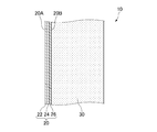
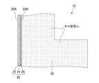
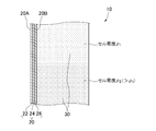
- FIG. 1 It is a perspective view showing the state where the interior material for vehicles of this embodiment constitutes the luggage compartment of a vehicle. It is a sectional view (the 1st composition) of a part of interior material for vehicles of this embodiment. It is a sectional view (the 2nd composition) of a part of interior material for vehicles of this embodiment. It is a sectional view (3rd composition) of a part of interior material for vehicles of this embodiment. It is a sectional view (fourth composition) of a part of interior material for vehicles of this embodiment.
- the interior material 10 of the present embodiment is, for example, interior walls on both sides (trunk sides) of the vehicle CB in a trunk TR (an example of a vehicle room) provided behind a rear seat RS of the vehicle CB. (See Figure 1).
- the interior material 10 is arrange
- the interior material 10 has a function (designing function) to provide an aesthetic appearance as an interior wall, a function (heat insulation function) to maintain the temperature in the trunk room TR, and the trunk room TR outside the trunk room TR (the interior material 10 is interposed in the trunk room TR). And the function to maintain the rigidity of the interior material 10 (stiffness maintaining mechanism).
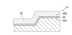
- the interior material 10 includes a base 20 and a foam layer 30, as shown in FIGS.
- the base material 20 of this embodiment is a plate-like member having a three-dimensional shape as an example (see FIG. 1 and FIGS. 7A to 12C), and the foam layer 30 is applied to one surface (FIGS. 5 and FIGS. 7A-12C).
- the interior material 10 (base material 20) has the other surface (surface opposite to the surface on which the foam layer 30 is applied) directed to the inside of the trunk room TR (see FIG. 1).
- the surface of the base material 20 facing the inside of the trunk TR is taken as the front surface 20A (an example of a design surface), and the surface opposite to the front surface 20A, ie, the foam layer 30 is applied.
- the back surface 20B is taken as the back side.
- the front surface 20A is a part of a design layer 22 described later (see FIGS. 2 to 5).
- the base material 20 of this embodiment is made into the plate-shaped member of a three-dimensional shape as an example, as FIG. 1 shows. Further, as shown in FIGS. 2 to 5, the base material 20 has, for example, a multilayer structure in which a design layer 22, a dyeing prevention layer 24, and an adhesive layer 26 are superimposed in the order of description. It is done.
- the design layer 22 of this embodiment is mainly for exerting a design function among the functions of the interior material 10 described above, and is made of, for example, polyester fiber, polypropylene fiber, polyethylene fiber, and other sheet materials. It is a member having a basis weight of 100 g / m 2 to 500 g / m 2 .
- the anti-staining layer 24 of the present embodiment is intended to prevent (or suppress) the exudation of the foam layer 30 to the design layer 22, and is made of, for example, a film of polypropylene, polyethylene, polyamide or the like. It is a member with an amount of 50 g / m 2 to 500 g / m 2 .
- the basis weight of the anti-staining layer 24 is preferably about 300 g / m 2 .
- the adhesive layer 26 of the present embodiment is for bonding (fixing) the foam layer 30 to the base material 20, and for example, the basis weight is 15 g / s composed of spunbond, spunlace, needle punch and other non-woven fabrics. It is a member of m 2 to 200 g / m 2 .
- the adhesive layer 26 bonds (fixes) the foam layer 30 to the base 20 by inserting a part of the foam layer 30 applied between the fibers (a gap between the fibers). That is, in the present embodiment, the base 20 and the foam layer 30 are not fixed to each other by an adhesive or the like, and a part of the foam layer 30 is formed on the adhesive layer 26 constituting the back surface 20B of the base 20. Are fixed by the so-called anchor effect.
- the foam layer 30 of the present embodiment is made to exhibit the heat insulation function and the sound absorption function among the functions of the interior material 10 described above, and is made of, for example, urethane foam FR.
- the foamed urethane FR is an example of a foamable resin, and refers to a urethane formed by including cells (cells) (see FIG. 7A, FIG. 8A, FIG. 11A and the like).
- the thickness of the foam layer 30 is, for example, 1 mm to 100 mm.
- the density of the foam layer 30 is, for example, 10 kg / m 3 to 300 kg / m 3 .
- the cell diameter of the cells (cells) formed in the foam layer 30 is, for example, 50 ⁇ m to 300 ⁇ m.
- the thermal conductivity of the foam layer 30 is, for example, 0.02 W / mk to 0.05 W / mk.
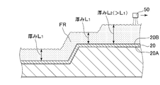
- the foam layer 30 of the present embodiment is a layer applied to the back surface 20B of the substrate 20. That is, the foam layer 30 is disposed between the base 20 and the vehicle body (body) constituting the vehicle CB. Also, as an example, the foam layer 30 has a configuration in which one portion is thicker than the other portion (see FIG. 3) at least in the surface direction of the substrate 20 (see FIG. 3) 4), or one portion is thicker than the other portion and the cell density is higher (see FIG. 5). And as an example, the said one part is comprised so that it may be closer to the noise source (as an example rear wheel (illustration omitted)) which comprises vehicle CB rather than the said other part.
- the foamed layer 30 may not be made of urethane, as long as it is applied to the base material 20 and exhibits a heat insulating function and a sound absorbing function while foaming a resin as described later. Also, in order to reinforce the strength of the foam layer 30 and to improve the dimensional stability, for example, the foam layer 30 may contain fibers (for example, glass fibers). That is, the foam layer 30 may be configured to include other than the foam resin.
- a fineness of 1200 tex to 4800 tex, a length of 5 mm to 100 mm, a basis weight of 10 g / m 2 to 200 g / m 2 , and a content of 1% to 20% in the foam layer 30 are preferable.
- the content in the foam layer 30 is preferably about 5%.
- the above-mentioned "increases dimensional stability" means making warpage deformation, shrinkage, and the like of the interior material 10 after molding unlikely to occur.
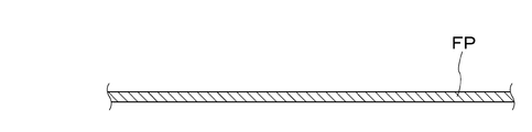
- the manufacturing method of the present embodiment is, as an example, a step of forming a flat plate FP (see FIG. 6A) into a base 20 (hereinafter referred to as a base forming step) and a step performed after the base forming step. And the step of applying the foamed urethane FR to the back surface 20B of the substrate 20 to form the foamed layer 30 (hereinafter referred to as a foamed layer forming step).
- the base material forming step is performed using a pressing apparatus 40 configured to include a fixed mold 40A and a movable mold 40B, as shown in FIGS. 6A to 6C.
- a flat plate FP having a multilayer structure in which the design layer 22, the anti-staining layer 24, and the adhesive layer 26 are stacked in the order described is prepared (see FIG. 6A).
- the flat plate FP is pressed by the pressing device 40 to form the three-dimensional base material 20. This is the end of the process.
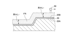
- FIGS. 7A to 12C are first to sixth patterns in the foam layer forming process, respectively, and have different characteristics.
- the foam layer forming step is performed for each pattern for convenience, but the manufacturing method of this embodiment is performed by combining any one or any two or more of the first to sixth patterns. .
- the foam layer forming step is performed using the spray 50 (see FIGS. 7A, 8A, 9A, 10A, 11A and 12A) in any of the patterns.
- the spray 50 is attached to a robot (not shown), and configured to spray the urethane foam FR while moving along a defined movement path.
- the urethane foam FR is injected toward the back surface 20B of the substrate 20 by the spray 50, and the urethane foam FR has the same thickness in the surface direction of the back surface 20B. It is applied. Then, as shown in FIG. 7B, when the foamed urethane FR applied to the base material 20 solidifies (when the foamed layer 30 is formed), this process ends.
- coated by 1st pattern becomes a structure in which the thickness of the whole is equivalent in the surface direction of the base material 20, while the cell density of the whole is equivalent.
- the foam layer 30 applied by the first pattern has a first configuration (see FIG. 2) as an example.
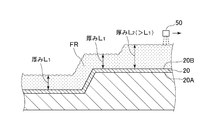
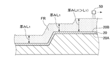
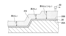
- the urethane foam FR is sprayed toward the back surface 20B of the substrate 20 by the spray 50, and the urethane foam FR is applied in different thicknesses with respect to the surface direction of the back surface 20B. Be done. Then, as shown in FIG. 8B, when the foamed urethane FR applied to the base material 20 solidifies (when the foamed layer 30 is formed), this process ends.
- the second pattern can be said to be a step of forming the foam layer 30 by making the application conditions different between one portion and the other portion of the foam layer 30.
- the foamed layer 30 applied by the second pattern has a configuration in which one portion is thicker than the other portion in the surface direction of the base material 20 while the overall cell density is the same.
- the foam layer 30 applied by the second pattern has a second configuration (see FIG. 3) as an example.
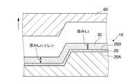
- the urethane foam FR is sprayed toward the back surface 20B of the substrate 20 by the spray 50, and the urethane foam FR has a similar thickness in the surface direction of the back surface 20B. It is applied.
- the movable die 60 an example of a mold
- the foamed urethane FR is sandwiched between 20 and pressurized to form a foamed layer 30 having a predetermined layer thickness.
- the foamed layer 30 applied by the third pattern has a configuration in which the overall thickness is the same in the surface direction of the base material 20 while the overall cell density is the same.
- the cell density of the foam layer 30 formed in the third pattern is lower than that of the foam layer 30 formed in the first pattern because the movable layer 60 is pressed.
- the foam layer 30 applied by the third pattern has a first configuration (see FIG. 2) as an example.
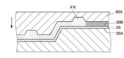
- the urethane foam FR is sprayed toward the back surface 20B of the substrate 20 by the spray 50, and the urethane foam FR is applied in different thicknesses with respect to the surface direction of the back surface 20B. Be done.
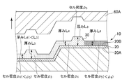
- the movable mold 60A before the foamed urethane FR applied to the base material 20 solidifies, the movable mold 60A having a concavo-convex shape not along the three-dimensional shape of the base material 20 (another example of mold ) And the base material 20, under pressure (partially different pressure conditions) with partially different pressure conditions sandwiching the urethane foam FR, to form a foam layer 30 having a partially different layer thickness.
- the present process ends.
- the cell density of one part in the surface direction of the base material 20 is higher than the cell density of the other part, and one in the surface direction of the base material 20.
- the part is thicker than the other parts.
- the foam layer 30 applied by the fourth pattern the cell density of one part in the surface direction of the substrate 20 is lower than the cell density of the other part, and the surface direction of the substrate 20 One part is thinner than the other part.
- the foam layer 30 applied by the fourth pattern is, for example, a layer including the third configuration (see FIG. 4) and the fourth configuration (see FIG. 5).
- the urethane foam FR is sprayed toward the back surface 20B of the substrate 20 by the spray 50, and the urethane foam FR is applied at a different thickness in the surface direction of the back surface 20B. Be done.
- the foamed urethane FR applied to the substrate 20 solidifies, the foamed urethane FR is formed by the movable mold 60 and the substrate 20 having a shape along the three-dimensional shape of the substrate 20. Press across the.
- the movable mold 60 is separated from the foam layer 30 after the foam urethane FR is solidified and the foam layer 30 is formed, the present process ends.
- the fifth pattern can be said to be a step of forming the foam layer 30 by making the application conditions different between one portion and the other portion of the foam layer 30.
- the cell density of one part in the surface direction of the base material 20 is lower than the cell density of the other part, and in the surface direction of the base material 20 The thickness is equal.
- the foam layer 30 applied by the fifth pattern has a third configuration (see FIG. 4).
- the urethane foam FR is sprayed toward the back surface 20B of the substrate 20 by the spray 50, and the urethane foam FR is applied at a different thickness in the surface direction of the back surface 20B. Be done.
- the movable mold 60B and the substrate having a shape along the three-dimensional shape of the foamed urethane FR applied to the substrate 20 are obtained.
- the urethane foam FR is sandwiched between the material 20 and pressed.
- the sixth pattern can be said to be a step of forming the foam layer 30 by making the application conditions different between one portion and the other portion of the foam layer 30. From the above, the foamed layer 30 applied by the sixth pattern has a configuration in which one portion is thicker than the other portion in the surface direction of the base material 20 while the overall cell density is the same.
- the foam layer 30 applied by the sixth pattern has a second configuration (see FIG. 3) as an example.
- the first effect is that the interior material 10 is provided with the foam layer 30 applied to the back surface 20B of the substrate 20.
- the interior material for vehicles disclosed in the aforementioned Patent Document 1 includes a felt.
- the interior material 10 of the present embodiment is provided with the foam layer 30 applied to the back surface 20B of the base 20 instead of the felt bonded to the base by the adhesive or the like (FIG. See Figure 5). Therefore, the interior material 10 of the present embodiment is reduced in weight while maintaining the same sound absorption as compared to a vehicle interior material provided with a base material and a felt adhered to the back surface of the base material.
- the vehicle equipped with the interior material 10 of the present embodiment has lower fuel consumption than the vehicle equipped with the vehicle interior material equipped with the base material and the felt bonded to the back surface of the base material. Become.
- the foam layer 30 of the present embodiment is not bonded to the back surface 20B of the base 20 with an adhesive or the like, and is formed by the above-described foam layer forming step. Therefore, the interior material 10 of the present embodiment is compared to the case of bonding and fixing while fixing the plate-like foam layer (not shown) prepared in advance to the three-dimensional base 20 while deforming it. It can be said that this is effective in that the internal stress (e.g., tensile stress and compressive stress in the bent portion) is kept low.
- the internal stress e.g., tensile stress and compressive stress in the bent portion
- the second effect is that one portion of the foam layer 30 is thicker than the other portion, higher in cell density, or thicker and higher in cell density.
- the overall thickness is the same in the surface direction of the base material 20 while the overall cell density is the same. Not adjusted.
- one portion of the foam layer 30 is different from the other portion. It also has a thick structure, a high cell density structure, and a thick and high cell density structure.
- the rigidity and the sound absorption can be improved by configuring one portion of the foam layer 30 to be thicker than the other portion, to have a high cell density, or to be thick and having a high cell density. It can be adjusted for each part.
- the first portion of the foam layer 30 is configured to be closer to the rear wheel (not shown, an example of a noise source) than the other portions, it is advantageous in sound absorption.
- the material cost of the urethane foam FR is reduced by making the part requiring high rigidity the above one part and setting the part not requiring high rigidity the other part. Can.
- the third effect is an effect of applying the foamed urethane FR to the substrate 20 to form the foam layer 30 in the manufacturing method of the present embodiment.
- the manufacturing method of the present embodiment is performed by applying the foam layer 30 to the back surface 20B of the base 20 instead of bonding the felt to the base with an adhesive or the like (FIG. 7A to FIG. 12C). Then, in the case of the present embodiment, a part of the foam layer 30 applied between the fibers (a gap between the fibers) of the adhesive layer 26 formed on the substrate 20 is caused to enter the foam layer on the substrate 20. Fix 30. Therefore, in the case of this embodiment, it is not necessary to apply an adhesive etc. to a substrate like the manufacturing method of the interior material for vehicles originally disclosed by the above-mentioned patent documents 1.
- the manufacturing method of the present embodiment has a shorter manufacturing time as compared to the case of bonding the felt to the substrate.
- the foamed urethane FR is advantageous in that the spray 50 does not need to be provided with a pressing mechanism and a heating mechanism, since it foams and hardens without heating in the spray 50.
- the fourth effect is achieved by using the spray 50 and the movable molds 60 and 60B in the manufacturing method of the present embodiment to make the application condition by the spray 50 different between the above one part and the above other part. It is an effect of applying foamed urethane FR to the back surface 20B of the material 20 and forming a foamed layer 30 having a predetermined layer thickness by pressing with the movable molds 60 and 60B. Specifically, this is the effect of the foam layer forming step of the fifth pattern (see FIGS. 11A to 11C) described above.
- the urethane foam UR is applied such that the application thickness of the urethane foam UR by the spray 50 is partially different.
- the thickness of the entire foam layer 30 is made equal in the surface direction of the base material 20 by a simple method, and then the first part in the surface direction of the base material 20 It can manufacture so that cell density may be lower than cell density of other parts.
- the manufacturing time is shorter than in the case of bonding the felt to the base material.
- the interior material 10 having the second effect can be manufactured easily or in a short time.
- the fifth effect is that in the manufacturing method of the present embodiment, the spray 50 and the movable die 60A are used to make the back surface of the substrate 20 different from the application condition by the spray 50 between the one portion and the other portion. It is an effect of forming the foaming layer 30 of different layer thickness by applying the foamed urethane FR to the surface 20B and changing the pressurizing condition by the movable die 60A. Specifically, this is the effect of the foam layer forming step of the above-mentioned fourth pattern (see FIGS. 10A to 10C).
- the coating thickness of the foamed urethane UR by the spray 50 is applied so as to be partially different, and shown in FIG.
- pressurizing step of the formed foam layer forming step by using the movable die 60A whose pressurizing surface is uneven, pressurization is performed under partially different pressure.
- the cell density of one portion in the surface direction of the substrate 20 is the other It can be manufactured to be lower than the cell density of the part of.
- the manufacturing time is short as compared with the case where the felt is adhered to the base material.
- the sixth effect is an effect of performing the foam layer forming step after the base material forming step in the manufacturing method of the present embodiment.
- the foam layer forming step is performed (see FIGS. 7A to 12C) after the base material forming step (see FIGS. 6A to 6C). Therefore, in the case of the present embodiment, peeling, deformation or the like of the foam layer 30 is not generated by the pressing process in the base material forming process.
- the base material forming step When the base material forming step is performed after the foam layer forming step, internal stress is generated in the foam layer 30 as the flat plate FP is first formed on the base member 20. However, in the case of the present embodiment, no internal stress of the foam layer 30 is generated due to the deformation of the flat plate FP to the base material 20 in the first place. Further, in the case of the present embodiment, since the foam layer forming step using the spray 50 is performed after the base material forming step, the portion to which the foam layer 30 is applied and the portion not coated are And can be easily divided.
- a felt sound absorbing material, not shown
- the ratio of the area of the part to which the felt is adhered to the entire back surface 20B is set to 20%.
- the percentage of the area of the portion of the entire back surface 20B to which the foam layer 30 of the press 10t is applied is 20%, and the portion of the press 30t to which the foam layer 30 is applied. The percentage of the area of 30%, and the percentage of the area of the portion where the foamed layer 30 of free 50t was applied was 50%.
- the press 10t (30t) refers to the thickness (mm) of the foam layer 30, that is, the foam urethane FR is applied to the back surface 20B of the substrate 20 by the spray 50 and then the foam urethane FR is pressed by the movable die 60.
- the foam layer 30 is 10 mm thick (30 mm thick).
- the urethane foam FR is naturally solidified without being pressed by the movable die 60, and the foam layer 30 having a thickness of 50 mm Means the case.
- Example 1 had better sound absorption than Comparative Example 1. As mentioned above, it turned out that this embodiment including Example 1 has at least equivalent sound absorption performance compared with a prior art.
- Comparative Example 2 only the base material 20 was used.
- the thickness of the base material 20 was 2.8 mm
- the thickness of the foamed layer 30 was 30 mm
- the basis weight was 1739 g / m 2
- the maximum load was 112.6 gf.
- the temperature of the die to be pressed was 25 ° C.
- the atmospheric temperature at the time of production was 10 ° C.
- the pressing time was 30 seconds.
- Example 2 has an elastic gradient equivalent to that of Comparative Example 2 (it has bending stiffness) although it is lighter than Comparative Example 2.
- Comparative Example 2 has high rigidity compared with comparative example 2.
- this embodiment including Example 2 has high rigidity compared with a prior art. From another point of view, it can be said that the present embodiment can be reduced in weight when it has the same rigidity as that of the prior art.
- Example 2 had a lower heat transmission coefficient than Comparative Example 2 regardless of the thickness. As mentioned above, this embodiment containing Example 2 has high heat insulation compared with a prior art.
- Example 1 and 2 As mentioned above, although the Example was described, the following can be said from the result of each test compared with the comparative examples 1 and 2 about Example 1 and 2 respectively. That is, it can be said that the present embodiment including the examples 1 and 2 exerts the effects described in the description of the above-described examples in addition to the above-described first to sixth effects. Specifically, it can be said that this embodiment has (1) sound absorption equal to or higher than that of Comparative Examples 1 and 2, (2) high rigidity and (3) high thermal insulation. . Then, the inventors of the present application found the above (1) to (3) from the results of the respective tests of the examples.
- the application condition in the foam film forming step is described as the amount (thickness) of the foamable resin sprayed by the spray 50. That is, in the present embodiment, the application condition is a difference in application thickness of the foamable resin.
- the application conditions may be conditions other than the application thickness of the foamable resin.
- mechanical conditions such as the nozzle diameter
- physical conditions such as viscosity
- the thickness, density, cell diameter and thermal conductivity of the foam layer 30 have been illustrated and described. However, these values are merely illustrative and may not be these values. For example, if the interior material 10 exhibits the heat insulation function, sound absorption function or rigidity maintenance function required by a vehicle equipped with the interior material 10 provided with the foam layer 30, the thickness, density, cell diameter and heat conduction of the foam layer 30 The rates may be different from the illustrated values. In addition, if the physical property value illustrated about the design layer 22, the anti-staining layer 24, and the contact bonding layer 26 which comprises the base material 20 is exhibited, the function of each layer will not be this limitation.
- the interior material 10 is described as an example of the trunk side wall of the trunk room TR of the vehicle CB (see FIG. 1).
- the interior material 10 may be mounted on the vehicle CB as a member different from the present embodiment.
- the interior material 10 is mounted on the vehicle CB as a package tray (also referred to as parcel shelf, not shown), side door (not shown), back door (not shown), pillar (not shown) or other vehicle members. It is also good. In these cases, it goes without saying that the shape of the base material 20 constituting each member is different from that of the present embodiment.
- the foam layer 30 may contain a fiber (for example, glass fiber).
- a spray (not shown) for spraying glass fiber is prepared, and in the foam layer forming step, the spray 50 and the spray for spraying glass fiber By simultaneously performing the spraying operation toward the back surface 20B, the respective sprays may be mixed on the back surface 20B.
- FIGS. 2 to 5 in each interior material 10, it is illustrated as if the foam layer 30 is applied to the entire area of the back surface 20B of the base material 20.
- FIGS. 2 to 5 are merely illustrations of the respective configurations (first to fourth configurations) of the present embodiment, and in each configuration, the foam layer 30 is applied to a part of the back surface 20B of the substrate 20. It can be said that a form, that is, a form in which the foam layer 30 is applied to a part of the back surface 20B of the substrate 20 and the foam layer 30 is not applied to the remaining part is included in the technical scope of the present invention. Even in the case of this modification, at least one or more of the above-described first to sixth effects are achieved.
- the form by which layers other than the foaming layer 30 are being fixed to all or one part of the remaining part is also a technical scope of this invention, while the foaming layer 30 is apply
- the interior material 10 in which the foam layer 30 is applied to a part of the entire range of the back surface 20B is included in the technical scope of the present invention. In this case (when the foam layer 30 is applied to a part of the entire range of the back surface 20B), for example, the foam layer 30 is applied to a portion (of the base 20) requiring rigidity and sound absorption.
- the interior material 10 can be reduced in weight as a whole by not applying it to unnecessary portions.
- FIG. 3 (2nd structure), in one part and the other part of back surface 20B of the base material 20, it was demonstrated that the thickness of the foam layer 30 differs and cell density is the same.
- FIG. 4 third configuration
- the thickness of the foam layer 30 is the same and the cell density is different in one part and the other part of the back surface 20B of the base material 20.
- FIG. 5 fourth configuration
- the cell density and thickness of the foam layer 30 are different between one portion and the other portion of the back surface 20B of the base 20 (the thickness of one portion is the other portion And the cell density of one part is higher than the cell density of the other part).
- 3A to 5 (second to fourth configurations) and one example of manufacturing of the interior material 10 of each configuration, are one portion and the other portion connected? It is illustrated like. However, one part and the other part may not be connected (may be separated). Even in the case of this modification, at least one or more of the above-described first to sixth effects can be achieved.
- Vehicle interior material 20 substrate 20A front surface (an example of a design surface) 20B back surface 30 foam layer 50 spray 60 movable type (example of mold) 60A movable type (example of mold) 60B Movable type (example of mold) CB Vehicle FR Foaming Urethane (Example of Foamable Resin) TR Trunk room (an example of a vehicle room)
Landscapes
- Engineering & Computer Science (AREA)
- Mechanical Engineering (AREA)
- Physics & Mathematics (AREA)
- Acoustics & Sound (AREA)
- Vehicle Interior And Exterior Ornaments, Soundproofing, And Insulation (AREA)
- Casting Or Compression Moulding Of Plastics Or The Like (AREA)
- Molding Of Porous Articles (AREA)
- Laminated Bodies (AREA)
Abstract
La présente invention concerne, selon un mode de réalisation, un matériau d'intérieur de véhicule (10) comprenant : un matériau de base (20) qui est disposé à l'intérieur d'un véhicule (CB) et qui se présente sous la forme d'une plaque, et qui est conçu pour avoir une surface avant (20A) orientée vers l'intérieur d'un habitacle de véhicule (TR); et une couche de mousse (30) qui est appliquée sur une surface arrière (20B) du matériau de base (20).
Priority Applications (1)
| Application Number | Priority Date | Filing Date | Title |
|---|---|---|---|
| JP2019532432A JP7177774B2 (ja) | 2017-07-27 | 2018-06-15 | 車両用内装材及び車両用内装材の製造方法 |
Applications Claiming Priority (2)
| Application Number | Priority Date | Filing Date | Title |
|---|---|---|---|
| JP2017-145459 | 2017-07-27 | ||
| JP2017145459 | 2017-07-27 |
Publications (1)
| Publication Number | Publication Date |
|---|---|
| WO2019021676A1 true WO2019021676A1 (fr) | 2019-01-31 |
Family
ID=65039542
Family Applications (1)
| Application Number | Title | Priority Date | Filing Date |
|---|---|---|---|
| PCT/JP2018/022959 Ceased WO2019021676A1 (fr) | 2017-07-27 | 2018-06-15 | Matériau d'intérieur de véhicule et procédé de fabrication de matériau d'intérieur de véhicule |
Country Status (2)
| Country | Link |
|---|---|
| JP (1) | JP7177774B2 (fr) |
| WO (1) | WO2019021676A1 (fr) |
Citations (3)
| Publication number | Priority date | Publication date | Assignee | Title |
|---|---|---|---|---|
| JPS5747483U (fr) * | 1980-08-27 | 1982-03-16 | ||
| JPS62194029U (fr) * | 1979-01-24 | 1987-12-10 | ||
| JP2006525916A (ja) * | 2003-05-01 | 2006-11-16 | コリンズ・アンド・エイクマン・プロダクツ・カンパニー | 選択的に施された発泡体を有する車両トリム要素とそれを製造する方法 |
-
2018
- 2018-06-15 JP JP2019532432A patent/JP7177774B2/ja active Active
- 2018-06-15 WO PCT/JP2018/022959 patent/WO2019021676A1/fr not_active Ceased
Patent Citations (3)
| Publication number | Priority date | Publication date | Assignee | Title |
|---|---|---|---|---|
| JPS62194029U (fr) * | 1979-01-24 | 1987-12-10 | ||
| JPS5747483U (fr) * | 1980-08-27 | 1982-03-16 | ||
| JP2006525916A (ja) * | 2003-05-01 | 2006-11-16 | コリンズ・アンド・エイクマン・プロダクツ・カンパニー | 選択的に施された発泡体を有する車両トリム要素とそれを製造する方法 |
Also Published As
| Publication number | Publication date |
|---|---|
| JP7177774B2 (ja) | 2022-11-24 |
| JPWO2019021676A1 (ja) | 2020-05-28 |
Similar Documents
| Publication | Publication Date | Title |
|---|---|---|
| US11241867B2 (en) | Multicomponent polymer resin, methods for applying the same, and composite laminate structure including the same | |
| US20210023830A1 (en) | High-strength low-heat release composites | |
| EP0765737B1 (fr) | Element insonorisant | |
| JP2005512143A (ja) | 多密度音響減衰積層体およびその製造方法 | |
| JP2019094439A (ja) | 成形用複合構造材、樹脂成形品、及び樹脂成形品の製造方法 | |
| KR20060045363A (ko) | 자동차 내장 천정재용 적층부재 | |
| JP2016124458A (ja) | 車両ルーフパネル用の積層成形体及びその製造方法 | |
| KR102764744B1 (ko) | 자동차용 트렁크 러기지보드 및 그 제조방법 | |
| JP7177774B2 (ja) | 車両用内装材及び車両用内装材の製造方法 | |
| WO2018190051A1 (fr) | Matériau de revêtement utilisé dans un plafond moulé pour véhicules | |
| CN105365000B (zh) | 用于实施包括具有木质材料带的外观层的装饰件的方法 | |
| JP6937185B2 (ja) | 車両用内装材 | |
| JP5318551B2 (ja) | ポリウレタン発泡体の成形方法 | |
| JP7322631B2 (ja) | 乗物用内装材の製造方法 | |
| JP2024025389A (ja) | 面状裏材と、その面状裏材を備えた車両用成形材の製造方法 | |
| KR101808766B1 (ko) | 자동차용 내,외장재 및 그 제조방법 | |
| JP2002127284A (ja) | 車両用内装シート | |
| JP2002052987A (ja) | 車両用天井内装シート | |
| JP3529484B2 (ja) | 吸音材付き車両内装品及びその製造方法 | |
| JP2013071712A (ja) | 成形体およびその成形方法 | |
| JP7656181B2 (ja) | パネル | |
| JP5574540B2 (ja) | 自動車用内装部品とその製造方法 | |
| JP7322630B2 (ja) | 乗物用内装材の製造方法 | |
| JP4848205B2 (ja) | 車両用内装材 | |
| KR20190037023A (ko) | 파형 버블구조를 갖는 차량용 내장재 및 그 제조방법 |
Legal Events
| Date | Code | Title | Description |
|---|---|---|---|
| 121 | Ep: the epo has been informed by wipo that ep was designated in this application |
Ref document number: 18839225 Country of ref document: EP Kind code of ref document: A1 |
|
| ENP | Entry into the national phase |
Ref document number: 2019532432 Country of ref document: JP Kind code of ref document: A |
|
| NENP | Non-entry into the national phase |
Ref country code: DE |
|
| 122 | Ep: pct application non-entry in european phase |
Ref document number: 18839225 Country of ref document: EP Kind code of ref document: A1 |