WO2019021692A1 - Batterie de stockage au plomb-acide - Google Patents
Batterie de stockage au plomb-acide Download PDFInfo
- Publication number
- WO2019021692A1 WO2019021692A1 PCT/JP2018/023257 JP2018023257W WO2019021692A1 WO 2019021692 A1 WO2019021692 A1 WO 2019021692A1 JP 2018023257 W JP2018023257 W JP 2018023257W WO 2019021692 A1 WO2019021692 A1 WO 2019021692A1
- Authority
- WO
- WIPO (PCT)
- Prior art keywords
- carbon material
- negative electrode
- electrode plate
- storage battery
- lead
- Prior art date
- Legal status (The legal status is an assumption and is not a legal conclusion. Google has not performed a legal analysis and makes no representation as to the accuracy of the status listed.)
- Ceased
Links
Images

Classifications
-
- H—ELECTRICITY
- H01—ELECTRIC ELEMENTS
- H01M—PROCESSES OR MEANS, e.g. BATTERIES, FOR THE DIRECT CONVERSION OF CHEMICAL ENERGY INTO ELECTRICAL ENERGY
- H01M4/00—Electrodes
- H01M4/02—Electrodes composed of, or comprising, active material
- H01M4/62—Selection of inactive substances as ingredients for active masses, e.g. binders, fillers
- H01M4/624—Electric conductive fillers
- H01M4/625—Carbon or graphite
-
- H—ELECTRICITY
- H01—ELECTRIC ELEMENTS
- H01M—PROCESSES OR MEANS, e.g. BATTERIES, FOR THE DIRECT CONVERSION OF CHEMICAL ENERGY INTO ELECTRICAL ENERGY
- H01M10/00—Secondary cells; Manufacture thereof
- H01M10/04—Construction or manufacture in general
- H01M10/0459—Cells or batteries with folded separator between plate-like electrodes
-
- H—ELECTRICITY
- H01—ELECTRIC ELEMENTS
- H01M—PROCESSES OR MEANS, e.g. BATTERIES, FOR THE DIRECT CONVERSION OF CHEMICAL ENERGY INTO ELECTRICAL ENERGY
- H01M10/00—Secondary cells; Manufacture thereof
- H01M10/06—Lead-acid accumulators
- H01M10/12—Construction or manufacture
-
- H—ELECTRICITY
- H01—ELECTRIC ELEMENTS
- H01M—PROCESSES OR MEANS, e.g. BATTERIES, FOR THE DIRECT CONVERSION OF CHEMICAL ENERGY INTO ELECTRICAL ENERGY
- H01M4/00—Electrodes
- H01M4/02—Electrodes composed of, or comprising, active material
- H01M4/14—Electrodes for lead-acid accumulators
Definitions
- the present invention relates to a lead storage battery.
- Lead storage batteries are used in a variety of applications in addition to automotive and industrial applications.
- the lead storage battery includes a negative electrode plate, a positive electrode plate, and an electrolytic solution.
- a separator is disposed between the negative electrode plate and the positive electrode plate.
- the negative electrode plate is wrapped with a bag-like separator made of polyethylene.
- a resin having a sulfone group or the like, barium sulfate, a carbonaceous conductive material and the like are added as an additive.
- PSOC partial charge state
- One aspect of the present invention is a lead storage battery, wherein the lead storage battery includes a negative electrode plate, a positive electrode plate, a bag-like separator, and an electrolytic solution, and the negative electrode plate includes a first carbon material, And 2) a carbon material, wherein the first carbon material has a particle diameter of 32 ⁇ m or more, and the second carbon material has a particle diameter of less than 32 ⁇ m, and the first carbon material
- the present invention relates to a lead-acid battery, wherein the ratio R2 / R1 of the powder resistance R2 of the second carbon material to the powder resistance R1 of: R2 / R1 is 15 or more and 420 or less, and the positive electrode plate is packaged with the bag-like separator .
- a lead-acid battery which has excellent life performance in both high rate PSOC cycle testing and deep discharge cycle testing.
- the present invention relates to a lead-acid battery including a negative electrode plate, a positive electrode plate, a bag-like separator, and an electrolytic solution.
- the negative electrode plate includes a negative electrode material containing a first carbon material and a second carbon material.
- the first carbon material has a particle size of 32 ⁇ m or more.
- the second carbon material has a particle size of less than 32 ⁇ m.
- the ratio (R2 / R1 ratio) of the powder resistance R2 of the second carbon material to the powder resistance R1 of the first carbon material is 15 or more and 420 or less.
- the positive electrode plate is packaged with a bag-like separator.
- the life performance (hereinafter also referred to as deep discharge cycle life) in the deep discharge cycle test is remarkably improved.
- the reason is not clear, when the positive electrode plate is packaged with a bag-like separator, the high concentration sulfuric acid generated in the vicinity of the positive electrode plate during charging becomes difficult to move out of the bag-like separator. Further, the electrolytic solution in the vicinity of the positive electrode plate is easily stirred in the vertical direction by the gas generated in the positive electrode plate. It is considered that the stratification in the vicinity of the positive electrode plate is remarkably suppressed by the synergistic action of these phenomena, and the deep discharge cycle life is improved.
- the diffusion region of the electrolytic solution widens, so that the high concentration sulfuric acid tends to settle, and the stratification tends to proceed.
- the charge reaction does not easily proceed in the lower part of the negative electrode plate, and lead sulfate is easily accumulated.
- the conductivity of the negative electrode plate is remarkably improved. It is considered that when the R2 / R1 ratio is controlled to the above range, a good conductive network is formed in the negative electrode material, and the formed conductive network is less likely to deteriorate. Such good conductive network construction improves charge acceptance even when a considerable amount of non-conductive lead sulfate is present in the negative electrode material.
- the negative electrode material does not contain the first carbon material and the second carbon material in which the R2 / R1 ratio satisfies 15 to 420, Life performance in the high rate PSOC cycle test (hereinafter also referred to as high rate PSOC cycle life) is well maintained.
- a ratio (s2 / s1 ratio) of the specific surface area s2 of the second carbon material to the specific surface area s1 of the first carbon material is preferably 10 or more and 500 or less.
- the chargeability is considered to be more uniform over the entire area of the negative electrode plate.
- the charge / discharge reaction of the positive electrode plate facing the negative electrode plate also becomes more uniform.
- softening and falling off of the positive electrode material on the upper portion of the positive electrode plate where charge and discharge are easily concentrated are suppressed.
- the amount of positive electrode material that floats the electrolyte decreases, which is deposited on the negative electrode plate, and short circuit (moss short circuit) due to growth and contact with the positive electrode plate Be suppressed.
- the negative electrode plate is usually composed of a negative electrode current collector (such as a negative electrode grid) and a negative electrode material.
- the negative electrode material is a portion obtained by removing the negative electrode current collector from the negative electrode plate.
- members such as a mat
- the negative electrode plate includes such a member (sticking member)
- the negative electrode material is one obtained by removing the negative electrode current collector and the sticking member.
- the thickness of the electrode plate is a thickness including a mat. When a mat is attached to the separator, the thickness of the mat is included in the thickness of the separator.
- the negative electrode material contains a negative electrode active material (lead or lead sulfate) which exhibits a capacity by a redox reaction.
- the negative electrode active material in a charged state is cancellous lead, but an unformed negative electrode plate is usually produced using lead powder.
- the negative electrode material includes a first carbon material and a second carbon material.
- the first carbon material has a particle size of 32 ⁇ m or more, and the second carbon material has a particle size of less than 32 ⁇ m.
- the first carbon material and the second carbon material can be separated and distinguished in the procedure described later.
- the negative electrode material may further contain an organic plasticizer, barium sulfate and the like, and may further contain other additives as needed.
- Carbon material As the first carbon material and the second carbon material, carbon black, graphite, hard carbon, soft carbon or the like can be used. Examples of carbon black include acetylene black, ketjen black, furnace black, lamp black and the like.
- the graphite may be any carbon material containing a graphite type crystal structure, and may be any of artificial graphite and natural graphite.
- the first carbon material and the second carbon material may each have, for example, a ratio of the powder resistance R2 of the second carbon material to the powder resistance R1 of the first carbon material (R2 / R1 ratio) of 15 to 420, for example
- the type of carbon material, the average particle size D 50 , the specific surface area, and the like may be adjusted.
- the first carbon material for example, at least one selected from the group consisting of graphite, hard carbon and soft carbon is preferable.
- the first carbon material preferably contains at least graphite.
- the second carbon material preferably contains at least carbon black.
- the peak appearing at 1300 cm -1 or 1350 cm -1 or less in the range of the Raman spectrum (D band), and the peak (G band) that appears in the range of 1550 cm -1 or 1600 cm -1 or less What has intensity ratio ID / IG is 0 or more and 0.9 or less is made into graphite.
- the R2 / R1 ratio may be 15 or more, preferably 20 or more, more preferably 25 or more, and 50 or more.
- the R2 / R1 ratio may be 420 or less, preferably 155 or less, more preferably 130 or less, and particularly preferably 70 or less.
- the lower limit value and the upper limit value may be arbitrarily combined.
- the preferable range of the R2 / R1 ratio may be 25 to 420, 25 to 155, 25 to 70, 50 to 420, 50 to 155, 50 to 130, 50 to 70, and the like. When the R2 / R1 ratio is in such a range, it is easy to secure an excellent high rate PSOC cycle life.
- the s2 / s1 ratio is, for example, preferably 10 or more, more preferably 20 or more, and may be 30 or more or 40 or more. Moreover, 500 or less is preferable, as for s2 / s1, 240 or less is more preferable, and 120 or less is still more preferable. The lower limit value and the upper limit value may be arbitrarily combined.
- the s2 / s1 ratio is 20 to 500, 20 to 400, 20 to 240, 20 to 120, 30 to 500, 30 to 400, 30 to 240, 30 to 120, 10 to 240, 10 to 120, 20 to 120, etc. It may be When the s2 / s1 ratio is in such a range, it is easy to secure a better high rate PSOC cycle life.
- the content of the first carbon material in the negative electrode material is, for example, 0.05% by mass or more and 3.0% by mass or less, and preferably 0.1% by mass or more. Moreover, Preferably it is 2.0 mass% or less, More preferably, it is 1.5 mass% or less. These upper limits and lower limits can be arbitrarily combined.
- the content of the first carbon material is 0.05% by mass or more, it becomes easy to improve the high rate PSOC cycle life.
- the content of the first carbon material is 3.0% by mass or less, the adhesion between the active material particles can be easily secured, so the generation of cracks in the negative electrode plate can be suppressed and the high-rate PSOC cycle life can be further improved easily Become.
- the content of the second carbon material in the negative electrode material is, for example, 0.03% by mass or more and 1.0% by mass or less, and preferably 0.05% by mass or more. Moreover, Preferably it is 0.5 mass% or less, More preferably, it is 0.3 mass% or less. These upper limits and lower limits can be arbitrarily combined. When the content of the second carbon material is 0.03% by mass or more, it becomes easy to improve the high rate PSOC cycle life. When the content of the second carbon material is 1.0% by mass or less, for example, high rate performance can be easily enhanced.
- the remaining ones on the sieve are regarded as the first carbon material without passing through the sieve eyes, and the sieve eyes are passed.
- the carbon material is placed on a sieve with a mesh size of 32 ⁇ m, and the sieve is lightly shaken for 5 minutes while sprinkling deionized water while sieving.
- the first carbon material remaining on the sieve is flushed with ion exchange water, recovered from the sieve, and separated from the ion exchange water by filtration.
- the second carbon material passed through the sieve is recovered by filtration using a nitrocellulose membrane filter (0.1 ⁇ m mesh).
- the recovered first and second carbon materials are dried at a temperature of 100 ° C. for 2 hours, respectively.
- the 32 ⁇ m mesh sieve one having a 32 ⁇ m mesh having a nominal mesh aperture specified in JIS Z 8801-1: 2006 is used.
- the content of each carbon material in the negative electrode material can be determined by measuring the mass of each carbon material separated in the above procedure and calculating the ratio (mass%) of the mass in 5 g of the ground sample. Just do it.
- the powder resistance R1 of the first carbon material and the powder resistance R2 of the second carbon material are the same as those of the first carbon material and the second carbon material separated in the procedure of the above (A) About each, 0.5 g of a sample is put into a powder resistance measurement system (for example, Mitsubishi Chemical Analytech Co., Ltd., MCP-PD 51 type), and a low resistance based on JIS K 7194: 1994 under a pressure of 3.18 MPa. -A value measured by a four-point probe method using a resistivity meter (for example, Loresta-GX MCP-T700 manufactured by Mitsubishi Chemical Analytech Co., Ltd.).
- a powder resistance measurement system for example, Mitsubishi Chemical Analytech Co., Ltd., MCP-PD 51 type
- a low resistance based on JIS K 7194: 1994 under a pressure of 3.18 MPa.
- -A value measured by a four-point probe method using a resistivity meter for example, Loresta-GX MCP-T700 manufactured
- the specific surface area s1 of the first carbon material and the specific surface area s2 of the second carbon material are the BET specific surface areas of the first carbon material and the second carbon material, respectively.
- the BET specific surface area can be determined by a gas adsorption method using a BET equation, using each of the first carbon material and the second carbon material separated in the procedure of the above (A).
- Each carbon material is pretreated by heating in nitrogen flow at a temperature of 150 ° C. for 1 hour.
- the BET specific surface area of each carbon material may be determined using the pretreated carbon material under the following conditions, for example, using the following apparatus.
- Measuring device Micromeritics TriStar 3000 Adsorption gas: Nitrogen gas with a purity of 99.99% or higher Adsorption temperature: Liquid nitrogen boiling point temperature (77 K) Calculation method of BET specific surface area: According to 7.2 of JIS Z 8830: 2013
- the fully charged state of the lead storage battery means, in the case of a liquid battery, constant current charging in a water tank at 25 ° C. until reaching 2.5 V / cell at a 5-hour rate current. It is in the state which performed constant current charge for 2 hours by 5 hour rate current. Also, in the case of a control valve type battery, in the fully charged state, constant current constant voltage charging of 2.23 V / cell is performed at a 5-hour rate current in an air tank at 25 ° C. When the current drops below 1 mCA, charging is complete.
- 1CA is a current value (A) of the same numerical value as the nominal capacity (Ah) of the battery.
- A the nominal capacity of the battery.
- 1CA is 30A and 1mCA is 30mA.
- the negative electrode material can contain an organic shrinkproofing agent.
- the organic flame retardant is an organic polymer containing sulfur, and generally contains one or more, preferably a plurality of aromatic rings in the molecule, and also contains sulfur as a sulfur-containing group.
- sulfur-containing groups the sulfonic acid or sulfonyl group, which is a stable form, is preferred.
- the sulphonic acid groups may be present in acid form or in salt form as Na salts.
- lignin may be used, and a condensate of formaldehyde with a sulfur-containing aromatic compound may be used.
- lignin include lignin and lignin derivatives.
- the lignin derivative is, for example, lignin sulfonic acid, a salt of lignin sulfonic acid (for example, an alkali metal salt such as a sodium salt) or the like.
- the organic plasticizers may be used alone or in combination of two or more.
- lignin and a condensate of an aromatic compound having a sulfur-containing group with formaldehyde may be used in combination.
- bisphenols, biphenyls, naphthalenes and the like are preferably used.
- Bisphenols, biphenyls and naphthalenes are a general term for compounds having a bisphenol skeleton, a biphenyl skeleton and a naphthalene skeleton, respectively, and each may have a substituent. These may be contained alone in the organic plasticizer, or two or more kinds may be contained.
- bisphenol bisphenol A, bisphenol S, bisphenol F etc. are preferable.
- the sulfur-containing group may be directly bonded to the aromatic ring of the aromatic compound, for example, may be bonded to the aromatic ring as an alkyl chain having a sulfur-containing group.
- the sulfur element content in the organic plasticizer is, for example, 400 ⁇ mol / g or more and 10000 ⁇ mol / g or less.
- the sulfur element content of lignin is, for example, 400 ⁇ mol / g or more and 1000 ⁇ mol / g or less.
- the sulfur element content of the condensate of the aromatic compound having a sulfur-containing group with formaldehyde is, for example, 2000 ⁇ mol / g or more and 10000 ⁇ mol / g or less, and preferably 3000 ⁇ mol / g or more and 9000 ⁇ mol / g or less.
- the content of the organic pressure-reduction agent contained in the negative electrode material is, for example, 0.01% by mass or more and 1.0% by mass or less, preferably 0.02% by mass or more, and 0.8% by mass or less. preferable. These upper limits and lower limits can be arbitrarily combined.
- the lead storage battery after formation Prior to quantitative analysis, the lead storage battery after formation is fully charged and then disassembled to obtain an anode plate to be analyzed. The obtained negative electrode plate is subjected to water washing and drying to remove the electrolyte solution in the negative electrode plate. Next, the negative electrode material is separated from the negative electrode plate to obtain an uncrushed initial sample.
- Infrared spectrum of powder to be analyzed UV-visible absorption spectrum of solution obtained by dissolving powder to be analyzed in distilled water etc.
- NMR spectrum of solution obtained by dissolving powder to be analyzed in solvent such as heavy water NMR spectrum of solution obtained by dissolving powder to be analyzed in solvent such as heavy water
- the negative electrode current collector may be formed by casting of lead (Pb) or lead alloy, or may be formed by processing a lead or lead alloy sheet. Examples of the processing method include expand processing, punching (punching) processing and the like.
- the lead alloy used for the negative electrode current collector may be any of a Pb—Sb based alloy, a Pb—Ca based alloy and a Pb—Ca—Sn based alloy. These lead alloys may further contain, as an additive element, at least one selected from the group consisting of Ba, Ag, Al, Bi, As, Se, Cu, and the like.
- the formation can be performed by charging the electrode group in a state in which the electrode group including the unformed negative electrode plate is immersed in an electrolytic solution containing sulfuric acid in the battery case of the lead storage battery. However, the formation may be performed before the assembly of the lead storage battery or the plate group. Spongy lead is formed by formation.
- the positive electrode plate of the lead storage battery is classified into a paste type and a clad type.
- the paste type positive electrode plate comprises a positive electrode current collector and a positive electrode material.
- the positive electrode material is held by the positive electrode current collector.
- the positive electrode current collector may be formed in the same manner as the negative electrode current collector, and can be formed by casting of lead or lead alloy, processing of lead or lead alloy sheet, or the like.
- the clad positive electrode plate includes a plurality of porous tubes, a cored bar inserted into each tube, a positive electrode material filled in the tube into which the cored bar is inserted, and a seat connecting the plurality of tubes. Equipped with
- a Pb—Ca based alloy or a Pb—Ca—Sn based alloy is preferable in terms of corrosion resistance and mechanical strength.
- the positive electrode current collector may have lead alloy layers different in composition, and a plurality of alloy layers may be provided. It is preferable to use a Pb-Sb based alloy as the core metal.
- the positive electrode material contains a positive electrode active material (lead dioxide or lead sulfate) which develops a capacity by a redox reaction.
- the positive electrode material may optionally contain other additives.
- the unformed paste type positive electrode plate is obtained by filling the positive electrode current collector with the positive electrode paste, aging and drying according to the case of the negative electrode plate. Thereafter, the unformed positive electrode plate is formed.
- the positive electrode paste is prepared by kneading lead powder, additives, water, sulfuric acid and the like.
- the clad positive electrode plate is formed by filling a tube in which a core metal is inserted with lead powder or lead powder in the form of a slurry, and connecting a plurality of tubes in a coordinated manner.
- the woven fabric and the non-woven fabric may be mainly composed of fibers, and for example, 60% by mass or more is formed of fibers.
- the woven fabric may be mainly composed of a woven or knitted fabric of fibers, and the non-woven fabric may be mainly composed of entangled fibers.
- fibers glass fibers, polymer fibers, pulp fibers and the like can be used.
- a woven or non-woven fabric containing polymer fibers and glass fibers is preferred.
- Woven and non-woven fabrics may be mats containing components other than fibers.
- components other than fibers acid-resistant inorganic powders, polymers as binding agents and the like can be mentioned.
- the microporous membrane may be mainly composed of components other than the fiber component.
- a composition containing a pore forming agent (polymer powder, oil, etc.) is extruded into a sheet, and then the pore forming agent is removed to form pores. It is formed by forming.
- the microporous membrane is preferably mainly composed of a polymer having acid resistance.
- polystyrene resin As a polymer which comprises a fiber, a binding agent, a microporous film etc., polyolefin, an acrylic resin, polyester (for example, polyethylene terephthalate) etc. are mentioned. It is preferable to use polyolefins, such as polyethylene and a polypropylene, as a polymer which comprises a microporous membrane especially.
- the porous sheet contains a thermoplastic polymer, the end portions can be joined by heat welding when forming the bag-like separator.
- the bag-like separator may be composed only of a woven or non-woven fabric, or may be composed only of a microporous membrane.
- the bag-like separator may be composed of a laminate of a woven or non-woven fabric and a microporous membrane, as required.
- the bag-like separator may be made of a material obtained by laminating different or the same kind of materials, or a material obtained by engaging unevenness of the different or the same materials having unevenness, or the like.
- a bag-shaped separator and a non-bag-shaped separator may be used in combination.
- the electrolytic solution is an aqueous solution containing sulfuric acid, and may be gelled if necessary.
- the specific gravity at 20 ° C. of the electrolytic solution in a fully charged lead-acid battery after formation is, for example, 1.10 to 1.35 g / cm 3 , and preferably 1.20 to 1.35 g / cm 3 .
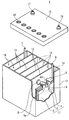
- the lead storage battery 1 includes a battery case 12 that accommodates an electrode plate group 11 and an electrolyte (not shown).
- the inside of the battery case 12 is partitioned into a plurality of cell chambers 14 by a partition wall 13.
- One electrode plate group 11 is accommodated in each cell chamber 14.
- the opening of the battery case 12 is sealed by a lid 15 having a positive electrode terminal 16 and a negative electrode terminal 17.
- the lid 15 is provided with a liquid port for each cell chamber, and a liquid port plug 18 is inserted into the liquid port. At the time of rehydration, the fluid port plug 18 is removed and refilling fluid is replenished from the fluid port.
- the electrode plate group 11 is configured by laminating a plurality of positive electrode plates 2 and negative electrode plates 3 which are respectively packaged by the bag-like separator 4.
- the positive electrode shelf 6 connecting the ears 2 a of the plurality of positive electrodes 2 in parallel is connected to the through connection body 8, and the ears of the plurality of negative electrodes 3
- the negative electrode shelf 5 connecting the 3 a in parallel is connected to the negative electrode post 7.
- the negative electrode post 7 is connected to the external negative electrode terminal 17 of the lid 15.
- the positive electrode post 9 is connected to the positive electrode shelf 6, and the through connection body 8 is connected to the negative electrode shelf 5.
- the positive electrode post 9 is connected to the positive electrode terminal 16 outside the lid 15.
- the through connection members 8 pass through the through holes provided in the partition walls 13 to connect the electrode plate groups 11 of the adjacent cell chambers 14 in series.
- the lead storage battery according to the present invention is summarized below and described.
- the lead storage battery includes a negative electrode plate, a positive electrode plate, a bag-like separator, and an electrolyte.
- the negative electrode plate includes a negative electrode material including a first carbon material and a second carbon material,
- the first carbon material has a particle size of 32 ⁇ m or more
- the second carbon material has a particle size of less than 32 ⁇ m
- the ratio R2 / R1 of the powder resistance R2 of the second carbon material to the powder resistance R1 of the first carbon material is 15 or more and 420 or less
- the positive electrode plate is packaged by the bag-like separator.
- the ratio s2 / s1 of the specific surface area s2 of the second carbon material to the specific surface area s1 of the first carbon material is, for example, 10 or more and 500 or less.
- the R2 / R1 ratio may be, for example, 20 or more, 25 or more, or 50 or more.
- the R2 / R1 ratio may be 155 or less, 130 or less, or 70 or less.
- the range of the R2 / R1 ratio is, for example, 25 to 420, 25 to 155, 25 to 70, or 50 to 420, and 50 to 155 It may be 50 to 130 or 50 to 70.
- the s2 / s1 ratio may be, for example, 20 or more, and may be 30 or more or 40 or more. Further, s2 / s1 may be 240 or less, or 120 or less.
- the range of the s2 / s1 ratio is, for example, 20 to 500, 20 to 400, 20 to 240, or 20 to 120, and 30 to 500. It may be 30 to 400, 30 to 240, 30 to 120, 10 to 240, 10 to 120, or 20 to 120.
- the content of the first carbon material in the negative electrode material is, for example, 0.05% by mass or more and 3.0% by mass or less, and preferably 0.1 It is mass% or more. Moreover, 2.0 mass% or less is preferable, More preferably, it is 1.5 mass% or less. These upper limits and lower limits can be arbitrarily combined.
- the content of the second carbon material in the negative electrode material is, for example, 0.03% by mass or more and 1.0% by mass or less, and preferably 0.05 It is mass% or more. Moreover, Preferably it is 0.5 mass% or less, More preferably, it is 0.3 mass% or less. These upper limits and lower limits can be arbitrarily combined.
- the first carbon material contains at least graphite
- the second carbon material contains at least carbon black
- ⁇ Lead acid battery A1 (1) Preparation of Negative Electrode Plate A lead paste, water, dilute sulfuric acid, a carbon material and an organic shrink-proof agent are mixed to obtain a negative electrode paste.
- the negative electrode paste is filled in the mesh portion of an expanded lattice made of a Pb—Ca—Sn-based alloy as a negative electrode current collector, aged, and dried to obtain an unformed negative electrode plate.
- a carbon material carbon black (Ketjen Black (registered trademark), average particle size D 50 : 40 nm) and graphite (average particle size D 50 : 110 ⁇ m) are used.
- organic pressure-reducing agent lignin is used, and the addition amount is adjusted so as to be 0.05% by mass so that the content contained in 100% by mass of the negative electrode material is blended in the negative electrode paste.
- Electrode Plate Lead powder, water, and sulfuric acid are kneaded to obtain a positive electrode paste.
- the positive electrode paste is filled in the mesh portion of an expanded lattice made of a Pb—Ca—Sn alloy, aged, and dried to obtain an unformed positive electrode plate.
- a non-formed positive electrode plate is accommodated in a bag-shaped separator formed of a microporous polyethylene film, and five non-formed negative electrode plates and four non-formed positive electrode plates per cell. Form a plate group.
- the electrode plate group is inserted into a polypropylene battery case, an electrolytic solution is injected, and formation is performed in the battery case to assemble a solution type automotive lead storage battery A1 having a nominal capacity of 30 Ah and a nominal voltage of 12 V.
- the terminal voltage of the lead storage battery is 2 V / cell.
- the content of the first carbon material contained in the negative electrode material is 0.3% by mass, and the content of the second carbon material is 1.5% by mass.
- the R2 / R1 ratio is 23.6.
- the ratio of the specific surface area S2 of the second carbon material to the specific surface area S1 of the first carbon material is 130.
- Lead-acid batteries A2 to A6 ⁇ The R2 / R1 ratio and the S2 / S1 ratio are changed as shown in Table 1 by adjusting the average particle diameter D 50 of each carbon material to be used, the specific surface area, the average aspect ratio of the first carbon material, and the like. Except for this, the negative electrode plate is produced in the same manner as the lead storage battery A1, and the lead storage batteries A2 to A8 are assembled in the same manner as the lead storage battery A1 except that the obtained negative electrode plate is used.
- lead storage battery AR Only carbon black (Ketjen Black (registered trademark), average particle diameter D 50 : 40 nm) is used as a carbon material. Aside from this, a negative electrode plate is produced in the same manner as the lead storage battery A1, and a lead storage battery AR is assembled in the same manner as the lead storage battery A1 except that the obtained negative electrode plate is used.
- carbon black Ketjen Black (registered trademark), average particle diameter D 50 : 40 nm
- Lead acid batteries B1 to B8 An unformed negative electrode plate, not an unformed positive electrode plate, is accommodated in a bag-like separator, and an electrode plate group is formed of five unformed negative electrode plates and four unformed positive electrode plates per cell. Other than this, lead acid batteries B1 to B8 are assembled in the same manner as lead acid batteries A1 to A8.
- lead storage battery BR An unformed negative electrode plate, not an unformed positive electrode plate, is accommodated in a bag-like separator, and an electrode plate group is formed of five unformed negative electrode plates and four unformed positive electrode plates per cell. Other than this, the lead storage battery BR is assembled in the same manner as the lead storage battery AR.
- Discharge Discharge for 2 hours at a constant current of 0.25 CA.
- Charge Charge for 5 hours at a maximum current of 0.25 CA at a constant voltage of 2.6 V / cell.
- the charge / discharge cycle is repeated 270 cycles, and when the current at the end of charge (5 hours) reaches 0.25 CA before reaching 270 cycles, it is determined that a moth short has occurred.
- controlling the R2 / R1 ratio in the range of 15 to 420 provides a lead-acid battery having excellent life performance in both deep discharge cycle test and high rate PSOC cycle test. I understand that. Above all, the high-rate PSOC cycle life is remarkably improved by setting the R2 / R1 ratio to 25 or more, and the high-rate PSOC cycle life is further remarkably improved by setting the R2 / R1 ratio to 50 or more. In addition, by controlling the s2 / s1 ratio in the range of 10 to 500, the occurrence of the moss short circuit is remarkably suppressed.
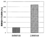
- the result of the deep discharge cycle test of the lead storage battery A3 and the lead storage battery B3 is shown in a bar graph in FIG. From this comparison, it can be understood that the deep discharge cycle life is remarkably improved by packaging the positive electrode plate with the bag-like separator, as compared to the case where the negative electrode plate is packaged with the bag-like separator.
- FIG. 3 shows the relationship between the R2 / R1 ratio of the lead storage batteries A1 to A8 and the lead storage batteries B1 to B8 and the high rate PSOC cycle life.
- the high-rate PSOC cycle life is shorter when the R2 / R1 ratio is less than 15 than when the negative electrode plate is packaged with a bag-like separator. That is, when the positive electrode plate is packaged with a bag-like separator, it is important to control the R2 / R1 ratio in order to obtain a good high-rate PSOC cycle life.
- the lead storage battery according to one aspect of the present invention is applicable to control valve type and liquid type lead storage batteries, and is a power supply for starting a car or a motorbike or an industrial storage device such as an electric vehicle (forklift truck) It can be suitably used as a power source for
Landscapes
- Chemical & Material Sciences (AREA)
- Chemical Kinetics & Catalysis (AREA)
- Electrochemistry (AREA)
- General Chemical & Material Sciences (AREA)
- Engineering & Computer Science (AREA)
- Manufacturing & Machinery (AREA)
- Battery Electrode And Active Subsutance (AREA)
- Cell Separators (AREA)
- Secondary Cells (AREA)
Abstract
Cette batterie de stockage d'acide de plomb est pourvue d'une plaque d'électrode négative, d'une plaque d'électrode positive, d'un séparateur de type sac et d'une solution d'électrolyte. La plaque d'électrode négative contient un matériau d'électrode négative qui contient un matériau carboné et du sulfate de baryum. Le matériau au carbone contient un premier matériau au carbone dont le diamètre de particules est supérieur ou égal à 32 μm et un deuxième matériau au carbone dont le diamètre de particules est inférieur à 32 μm ; et le ratio de la résistance de poudre (R2) du deuxième matériau au carbone sur la résistance de poudre (R1) du premier matériau au carbone, soit R2/R1 est compris entre 15 et 420 (inclus). La plaque d'électrode positive est conditionnée dans le séparateur de type sac.
Priority Applications (3)
| Application Number | Priority Date | Filing Date | Title |
|---|---|---|---|
| CN201880048720.1A CN110959223B (zh) | 2017-07-24 | 2018-06-19 | 铅蓄电池 |
| EP18838664.3A EP3633781B1 (fr) | 2017-07-24 | 2018-06-19 | Batterie au plomb-acide |
| JP2019532440A JP7124828B2 (ja) | 2017-07-24 | 2018-06-19 | 鉛蓄電池 |
Applications Claiming Priority (2)
| Application Number | Priority Date | Filing Date | Title |
|---|---|---|---|
| JP2017-142684 | 2017-07-24 | ||
| JP2017142684 | 2017-07-24 |
Publications (1)
| Publication Number | Publication Date |
|---|---|
| WO2019021692A1 true WO2019021692A1 (fr) | 2019-01-31 |
Family
ID=65039576
Family Applications (1)
| Application Number | Title | Priority Date | Filing Date |
|---|---|---|---|
| PCT/JP2018/023257 Ceased WO2019021692A1 (fr) | 2017-07-24 | 2018-06-19 | Batterie de stockage au plomb-acide |
Country Status (4)
| Country | Link |
|---|---|
| EP (1) | EP3633781B1 (fr) |
| JP (1) | JP7124828B2 (fr) |
| CN (1) | CN110959223B (fr) |
| WO (1) | WO2019021692A1 (fr) |
Cited By (4)
| Publication number | Priority date | Publication date | Assignee | Title |
|---|---|---|---|---|
| JP2023020656A (ja) * | 2021-07-30 | 2023-02-09 | 古河電池株式会社 | 液式鉛蓄電池およびその製造方法 |
| JP2023058773A (ja) * | 2021-10-14 | 2023-04-26 | 古河電池株式会社 | 液式鉛蓄電池 |
| US11864321B2 (en) | 2020-12-18 | 2024-01-02 | Te Connectivity Germany Gmbh | Electrical element, method of preparing an electrical element for a soldering step, and device for preparing an electrical element for a soldering step |
| JP2024056827A (ja) * | 2019-09-27 | 2024-04-23 | 株式会社Gsユアサ | 鉛蓄電池、電源装置および電源装置の使用方法 |
Citations (7)
| Publication number | Priority date | Publication date | Assignee | Title |
|---|---|---|---|---|
| JPH05135757A (ja) * | 1991-11-11 | 1993-06-01 | Matsushita Electric Ind Co Ltd | 鉛蓄電池 |
| WO2011090113A1 (fr) * | 2010-01-21 | 2011-07-28 | 株式会社Gsユアサ | Plaque cathodique pour batterie au plomb, procédé de production correspondant, et batterie au plomb |
| WO2011108056A1 (fr) * | 2010-03-01 | 2011-09-09 | 新神戸電機株式会社 | Accumulateur au plomb |
| JP2012089310A (ja) * | 2010-10-18 | 2012-05-10 | Gs Yuasa Corp | 鉛蓄電池 |
| JP2013041848A (ja) * | 2012-10-25 | 2013-02-28 | Shin Kobe Electric Mach Co Ltd | 鉛蓄電池 |
| JP2016154131A (ja) * | 2015-02-18 | 2016-08-25 | 株式会社Gsユアサ | 鉛蓄電池 |
| JP2017054629A (ja) | 2015-09-08 | 2017-03-16 | 日立化成株式会社 | 鉛蓄電池 |
Family Cites Families (8)
| Publication number | Priority date | Publication date | Assignee | Title |
|---|---|---|---|---|
| JP5797384B2 (ja) * | 2009-08-27 | 2015-10-21 | 古河電池株式会社 | 鉛蓄電池用複合キャパシタ負極板及び鉛蓄電池 |
| KR20130130751A (ko) * | 2010-12-21 | 2013-12-02 | 신코베덴키 가부시키가이샤 | 연축전지 |
| EP3059796B1 (fr) * | 2015-02-18 | 2018-05-16 | GS Yuasa International Ltd. | Batterie plomb-acide |
| EP3059789B1 (fr) * | 2015-02-18 | 2020-09-16 | GS Yuasa International Ltd. | Batterie au plomb-acide |
| JP6115796B2 (ja) * | 2015-02-18 | 2017-04-19 | 株式会社Gsユアサ | 鉛蓄電池 |
| CN104835965B (zh) * | 2015-05-22 | 2017-03-15 | 清远市凯捷电源有限公司 | 一种摩托车用铅碳电池及其制备方法 |
| CN106711451A (zh) * | 2015-08-12 | 2017-05-24 | 广隆光电科技股份有限公司 | 铅炭电池的负极铅膏、负极板及铅炭电池 |
| WO2019188056A1 (fr) * | 2018-03-29 | 2019-10-03 | 株式会社Gsユアサ | Batterie de stockage au plomb-acide |
-
2018
- 2018-06-19 WO PCT/JP2018/023257 patent/WO2019021692A1/fr not_active Ceased
- 2018-06-19 CN CN201880048720.1A patent/CN110959223B/zh not_active Expired - Fee Related
- 2018-06-19 EP EP18838664.3A patent/EP3633781B1/fr active Active
- 2018-06-19 JP JP2019532440A patent/JP7124828B2/ja active Active
Patent Citations (7)
| Publication number | Priority date | Publication date | Assignee | Title |
|---|---|---|---|---|
| JPH05135757A (ja) * | 1991-11-11 | 1993-06-01 | Matsushita Electric Ind Co Ltd | 鉛蓄電池 |
| WO2011090113A1 (fr) * | 2010-01-21 | 2011-07-28 | 株式会社Gsユアサ | Plaque cathodique pour batterie au plomb, procédé de production correspondant, et batterie au plomb |
| WO2011108056A1 (fr) * | 2010-03-01 | 2011-09-09 | 新神戸電機株式会社 | Accumulateur au plomb |
| JP2012089310A (ja) * | 2010-10-18 | 2012-05-10 | Gs Yuasa Corp | 鉛蓄電池 |
| JP2013041848A (ja) * | 2012-10-25 | 2013-02-28 | Shin Kobe Electric Mach Co Ltd | 鉛蓄電池 |
| JP2016154131A (ja) * | 2015-02-18 | 2016-08-25 | 株式会社Gsユアサ | 鉛蓄電池 |
| JP2017054629A (ja) | 2015-09-08 | 2017-03-16 | 日立化成株式会社 | 鉛蓄電池 |
Cited By (5)
| Publication number | Priority date | Publication date | Assignee | Title |
|---|---|---|---|---|
| JP2024056827A (ja) * | 2019-09-27 | 2024-04-23 | 株式会社Gsユアサ | 鉛蓄電池、電源装置および電源装置の使用方法 |
| US11864321B2 (en) | 2020-12-18 | 2024-01-02 | Te Connectivity Germany Gmbh | Electrical element, method of preparing an electrical element for a soldering step, and device for preparing an electrical element for a soldering step |
| JP2023020656A (ja) * | 2021-07-30 | 2023-02-09 | 古河電池株式会社 | 液式鉛蓄電池およびその製造方法 |
| JP2023058773A (ja) * | 2021-10-14 | 2023-04-26 | 古河電池株式会社 | 液式鉛蓄電池 |
| JP7660053B2 (ja) | 2021-10-14 | 2025-04-10 | 古河電池株式会社 | 液式鉛蓄電池 |
Also Published As
| Publication number | Publication date |
|---|---|
| EP3633781A4 (fr) | 2020-07-29 |
| EP3633781A1 (fr) | 2020-04-08 |
| JPWO2019021692A1 (ja) | 2020-05-28 |
| JP7124828B2 (ja) | 2022-08-24 |
| CN110959223B (zh) | 2023-09-15 |
| EP3633781B1 (fr) | 2024-04-24 |
| CN110959223A (zh) | 2020-04-03 |
Similar Documents
| Publication | Publication Date | Title |
|---|---|---|
| JP7355005B6 (ja) | 鉛蓄電池 | |
| JP7143927B2 (ja) | 鉛蓄電池 | |
| WO2019087686A1 (fr) | Accumulateur au plomb | |
| WO2019021692A1 (fr) | Batterie de stockage au plomb-acide | |
| JP6756182B2 (ja) | 鉛蓄電池 | |
| JP6766504B2 (ja) | 鉛蓄電池 | |
| JP6954353B2 (ja) | 鉛蓄電池 | |
| JP7111099B2 (ja) | 鉛蓄電池 | |
| WO2019087683A1 (fr) | Batterie de stockage au plomb | |
| JP7099450B2 (ja) | 鉛蓄電池 | |
| WO2019087682A1 (fr) | Batterie de stockage au plomb | |
| WO2019087679A1 (fr) | Accumulateur au plomb | |
| WO2019087680A1 (fr) | Batterie de stockage au plomb | |
| JP6750377B2 (ja) | 鉛蓄電池 | |
| JP2024104758A (ja) | 鉛蓄電池 | |
| JP7099448B2 (ja) | 鉛蓄電池 | |
| JP7099452B2 (ja) | 鉛蓄電池 | |
| JP6750376B2 (ja) | 鉛蓄電池 | |
| JPWO2019225161A1 (ja) | 鉛蓄電池 | |
| JP2020102359A (ja) | 鉛蓄電池 | |
| JP7694585B2 (ja) | 鉛蓄電池用クラッド式正極板および鉛蓄電池 | |
| JP2018190570A (ja) | 鉛蓄電池 | |
| WO2024005041A1 (fr) | Batterie au plomb-acide | |
| JP2024029809A (ja) | 鉛蓄電池 | |
| JP2024029810A (ja) | 鉛蓄電池 |
Legal Events
| Date | Code | Title | Description |
|---|---|---|---|
| 121 | Ep: the epo has been informed by wipo that ep was designated in this application |
Ref document number: 18838664 Country of ref document: EP Kind code of ref document: A1 |
|
| ENP | Entry into the national phase |
Ref document number: 2019532440 Country of ref document: JP Kind code of ref document: A |
|
| ENP | Entry into the national phase |
Ref document number: 2018838664 Country of ref document: EP Effective date: 20200102 |
|
| NENP | Non-entry into the national phase |
Ref country code: DE |