WO2019021701A1 - Module à membranes à fibres creuses - Google Patents
Module à membranes à fibres creuses Download PDFInfo
- Publication number
- WO2019021701A1 WO2019021701A1 PCT/JP2018/023497 JP2018023497W WO2019021701A1 WO 2019021701 A1 WO2019021701 A1 WO 2019021701A1 JP 2018023497 W JP2018023497 W JP 2018023497W WO 2019021701 A1 WO2019021701 A1 WO 2019021701A1
- Authority
- WO
- WIPO (PCT)
- Prior art keywords
- hollow fiber
- fiber membrane
- bypass pipe
- membranes
- membrane element
- Prior art date
- Legal status (The legal status is an assumption and is not a legal conclusion. Google has not performed a legal analysis and makes no representation as to the accuracy of the status listed.)
- Ceased
Links
Images

Classifications
-
- B—PERFORMING OPERATIONS; TRANSPORTING
- B01—PHYSICAL OR CHEMICAL PROCESSES OR APPARATUS IN GENERAL
- B01D—SEPARATION
- B01D61/00—Processes of separation using semi-permeable membranes, e.g. dialysis, osmosis or ultrafiltration; Apparatus, accessories or auxiliary operations specially adapted therefor
- B01D61/002—Forward osmosis or direct osmosis
-
- B—PERFORMING OPERATIONS; TRANSPORTING
- B01—PHYSICAL OR CHEMICAL PROCESSES OR APPARATUS IN GENERAL
- B01D—SEPARATION
- B01D63/00—Apparatus in general for separation processes using semi-permeable membranes
- B01D63/02—Hollow fibre modules
- B01D63/04—Hollow fibre modules comprising multiple hollow fibre assemblies
-
- B—PERFORMING OPERATIONS; TRANSPORTING
- B01—PHYSICAL OR CHEMICAL PROCESSES OR APPARATUS IN GENERAL
- B01D—SEPARATION
- B01D63/00—Apparatus in general for separation processes using semi-permeable membranes
- B01D63/02—Hollow fibre modules
- B01D63/025—Bobbin units
-
- B—PERFORMING OPERATIONS; TRANSPORTING
- B01—PHYSICAL OR CHEMICAL PROCESSES OR APPARATUS IN GENERAL
- B01D—SEPARATION
- B01D63/00—Apparatus in general for separation processes using semi-permeable membranes
- B01D63/02—Hollow fibre modules
- B01D63/033—Specific distribution of fibres within one potting or tube-sheet
-
- B—PERFORMING OPERATIONS; TRANSPORTING
- B01—PHYSICAL OR CHEMICAL PROCESSES OR APPARATUS IN GENERAL
- B01D—SEPARATION
- B01D2313/00—Details relating to membrane modules or apparatus
- B01D2313/08—Flow guidance means within the module or the apparatus
- B01D2313/083—Bypass routes
-
- B—PERFORMING OPERATIONS; TRANSPORTING
- B01—PHYSICAL OR CHEMICAL PROCESSES OR APPARATUS IN GENERAL
- B01D—SEPARATION
- B01D2313/00—Details relating to membrane modules or apparatus
- B01D2313/10—Specific supply elements
- B01D2313/105—Supply manifolds
-
- B—PERFORMING OPERATIONS; TRANSPORTING
- B01—PHYSICAL OR CHEMICAL PROCESSES OR APPARATUS IN GENERAL
- B01D—SEPARATION
- B01D2313/00—Details relating to membrane modules or apparatus
- B01D2313/21—Specific headers, end caps
-
- B—PERFORMING OPERATIONS; TRANSPORTING
- B01—PHYSICAL OR CHEMICAL PROCESSES OR APPARATUS IN GENERAL
- B01D—SEPARATION
- B01D2313/00—Details relating to membrane modules or apparatus
- B01D2313/44—Cartridge types
-
- B—PERFORMING OPERATIONS; TRANSPORTING
- B01—PHYSICAL OR CHEMICAL PROCESSES OR APPARATUS IN GENERAL
- B01D—SEPARATION
- B01D2313/00—Details relating to membrane modules or apparatus
- B01D2313/56—Specific mechanisms for loading the membrane in a module
-
- B—PERFORMING OPERATIONS; TRANSPORTING
- B01—PHYSICAL OR CHEMICAL PROCESSES OR APPARATUS IN GENERAL
- B01D—SEPARATION
- B01D2315/00—Details relating to the membrane module operation
- B01D2315/10—Cross-flow filtration
-
- B—PERFORMING OPERATIONS; TRANSPORTING
- B01—PHYSICAL OR CHEMICAL PROCESSES OR APPARATUS IN GENERAL
- B01D—SEPARATION
- B01D2315/00—Details relating to the membrane module operation
- B01D2315/22—Membrane contactor
-
- B—PERFORMING OPERATIONS; TRANSPORTING
- B01—PHYSICAL OR CHEMICAL PROCESSES OR APPARATUS IN GENERAL
- B01D—SEPARATION
- B01D61/00—Processes of separation using semi-permeable membranes, e.g. dialysis, osmosis or ultrafiltration; Apparatus, accessories or auxiliary operations specially adapted therefor
- B01D61/02—Reverse osmosis; Hyperfiltration ; Nanofiltration
-
- B—PERFORMING OPERATIONS; TRANSPORTING
- B01—PHYSICAL OR CHEMICAL PROCESSES OR APPARATUS IN GENERAL
- B01D—SEPARATION
- B01D63/00—Apparatus in general for separation processes using semi-permeable membranes
- B01D63/02—Hollow fibre modules
- B01D63/04—Hollow fibre modules comprising multiple hollow fibre assemblies
- B01D63/043—Hollow fibre modules comprising multiple hollow fibre assemblies with separate tube sheets
Definitions
- the present invention relates to a hollow fiber membrane module.
- a membrane module In water treatment using a membrane separation method, a membrane module is used in which a pressure vessel is loaded with a membrane element in which the membranes are assembled into one component.
- the membrane area per membrane module volume can be made large. For this reason, the amount of water permeability can be made large as the whole module, volume efficiency is very high, and it is excellent in compactness.
- Patent Document 1 International Publication No. 2004/069391
- Patent Document 2 Japanese Patent Publication No. 2015-160157
- the supply port for supplying the fluid to the inside of the hollow fiber membrane is usually disposed at one end of the hollow fiber membrane element, and the discharge port for discharging the fluid having passed through the inside of the hollow fiber membrane is the supply port. Is located at the opposite end of the
- This invention is made in view of said subject, The objective is to provide the hollow fiber membrane module which can improve the working efficiency in replacement
- a hollow fiber membrane module comprising Each of the at least one hollow fiber membrane element includes a plurality of hollow fiber membranes having openings at both ends, a bypass pipe, and a supply port and a discharge port provided on one end side in the longitudinal direction, The supply port communicates with the inflow side openings of the plurality of hollow fiber membranes,
- the bypass pipe is provided in the longitudinal direction of the at least one hollow fiber membrane element, and has a bypass pipe inlet at an end on the outlet side opening of the hollow fiber membrane, and the inflow of the hollow fiber membrane Has a bypass pipe outlet at the end on the side opening side,
- a hollow fiber membrane module wherein the outlet side openings of the plurality of hollow fiber membranes are in communication with the bypass pipe inlet and the bypass pipe outlet is in communication with the outlet.
- the at least one hollow fiber membrane element is two hollow fiber membrane elements, and in each of the two hollow fiber membrane elements, the supply port and the discharge port are opposite to the other hollow fiber membrane element
- the hollow fiber membrane module according to (1) which is provided on the side.
- the hollow fiber membrane module according to (1) or (2) which is for isotonic pressure membrane separation.
- the at least one hollow fiber membrane element includes a hollow fiber membrane winding body in which a plurality of the hollow fiber membranes are spirally wound around a central axis.
- the hollow fiber membrane module which can improve the working efficiency in replacement
- FIG. 1 is a schematic cross-sectional view showing an example of a hollow fiber membrane module of Embodiment 1. It is a cross-sectional schematic diagram which shows the modification of the hollow fiber membrane module of Embodiment 1.
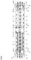
- FIG. It is a cross-sectional schematic diagram which shows an example of the hollow fiber membrane module of Embodiment 2.
- FIG. It is a cross-sectional schematic diagram which shows the modification of the hollow fiber membrane module of Embodiment 2.
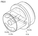
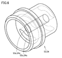
- FIG. It is a schematic diagram which shows a distributor.
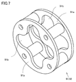
- FIG. 7 is a schematic view showing another type of distributor. It is a schematic diagram which shows a thrust pipe.
- the hollow fiber membrane module of the present invention comprises one pressure vessel and at least one hollow fiber membrane element loaded in the pressure vessel.
- Each of the at least one hollow fiber membrane element includes a plurality of hollow fiber membranes having openings at both ends, a bypass pipe, and a supply port and a discharge port provided on one longitudinal end side.
- the supply port communicates with the inflow side openings of the plurality of hollow fiber membranes
- the bypass pipe is provided in the longitudinal direction of the hollow fiber membrane element, has a bypass pipe inlet at the end on the outlet side opening of the hollow fiber membrane, and the end on the inlet side of the hollow fiber membrane Have a bypass pipe outlet,
- the outlet side openings of the plurality of hollow fiber membranes are in communication with the bypass pipe inlet, and the bypass pipe outlet is in communication with the outlet.
- the at least one hollow fiber membrane element is two hollow fiber membrane elements, In each of the two hollow fiber membrane elements, it is preferable that the supply port and the discharge port be provided on the opposite side of the other hollow fiber membrane element.
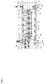
- the hollow fiber membrane module of the present embodiment is a single element type hollow fiber membrane module in which one hollow fiber membrane element is loaded in one pressure vessel 1.
- the feed solution (FS) flows on the outer side 31 of the hollow fiber membrane 41, and the draw solution (DS) flows inside the hollow fiber membrane 41 (hollow part).
- DS can be diluted or FS can be concentrated by extracting fresh water in FS to DS.
- the hollow fiber membrane element comprises a porous distribution pipe 21 having a plurality of holes 21a arranged at the center, a plurality of hollow fiber membranes 41 arranged around the periphery, a porous distribution pipe 21 and a plurality of hollow fiber membranes 41 And a resin wall 61 fixed at both ends of the Each of the plurality of hollow fiber membranes 41 has an opening at its both ends.
- the openings of the hollow fiber membranes are independently connected to the supply port and the discharge port. That is, the hollow fiber membrane element has the DS supply port 11a and the discharge port 11b communicating with the inside of the plurality of hollow fiber membranes 41 and the outside of the hollow fiber membrane module, and the inflow side opening 41a of the hollow fiber membrane 41 is DS
- the outlet side opening 41 b is connected to the supply port 11 a and is in communication with the DS outlet 11 b.
- the porous part piping 21 is not particularly limited as long as it is a tubular body having a plurality of holes.
- FS supplied from the FS supply port 10a into the hollow fiber membrane module can be distributed to the outer side 31 of the hollow fiber membrane.
- the holes are preferably provided radially in each direction.
- the porous part piping be located substantially at the center of the hollow fiber membrane element.
- the diameter of the porous distribution pipe 21 is too large, the area occupied by the hollow fiber membrane in the membrane module is reduced, and as a result, the membrane area of the hollow fiber membrane element or the membrane module is reduced, the water permeability per volume is reduced. There is.
- the diameter of the porous pipe is too small, the pressure loss increases when the feed fluid flows in the porous distribution pipe, and as a result, the effective differential pressure applied to the hollow fiber membrane may be reduced and the processing efficiency may be reduced. .
- the strength may be reduced, and the tension of the hollow fiber membrane, which is received when the supply fluid flows through the hollow fiber membrane layer, may cause breakage of the perforated pipe. It is important to set the optimum diameter by comprehensively considering these effects.
- the area ratio of the cross-sectional area of the porous pipe (excluding the cross-sectional area of the bypass pipe) to the cross-sectional area of the hollow fiber membrane element is preferably 4 to 20%.
- the bypass pipe 81 is a pipe provided in the hollow fiber membrane element in the longitudinal direction and has a bypass pipe inlet 81a at the end on the outflow side opening of the hollow fiber membrane, and the inflow side of the hollow fiber membrane A bypass pipe outlet 81 b is provided at the end on the opening side.
- the bypass pipe inlet 81a is in communication with the flow path 51a (see FIG. 5) of the distributor 51, and the bypass pipe outlet 81b is in communication with the flow path 53a (see FIG. 6) inside the distributor 53.
- the flow path 51 c of the distributor 51 is sealed by the plug 55 so that the fluid can not pass therethrough.
- the bypass pipe 81 does not have to be parallel to the longitudinal direction of the hollow fiber membrane element, and may be any pipe that passes through the hollow fiber membrane element in the longitudinal direction. Moreover, in this embodiment, although the bypass pipe 81 is installed in the inside of the porous distribution pipe, it is not limited to such a form, You may pass through the other part in a hollow fiber membrane element.
- the thrust pipe 91 is a structure in which two disk-like members 91a having an opening 91b are joined via four cylinders.
- the thrust pipe 91 is disposed between the hollow fiber membrane element and the wall members 13 and 14 in the hollow fiber membrane module. Since the thrust pipe 91 has the opening 91b, when the FS flows from the FS supply port 10a, the hollow fiber membrane element can be fixed by the two disk-shaped members 91a without blocking the flow thereof. it can. Therefore, when the hollow fiber membrane module is filled with the fluid, it is possible to prevent the hollow fiber membrane element from floating and becoming unstable in the hollow fiber membrane module.
- the DS supplied from the DS supply port 11a flows into the hollow fiber membrane 41 from the inflow side opening 41a of the hollow fiber membrane 41 in the hollow fiber membrane element, and the outflow on the other end side It flows out from the side opening 41b.
- the flowed-out DS flows from the flow path 51b of the distributor 51 to 51a (see FIG. 5) and flows into the bypass pipe 81 from the bypass pipe inlet 81a of the bypass pipe 81. Thereafter, it is taken out from the DS outlet 11b through the flow path 53a (see FIG. 6) inside the distributor 53 to which the bypass pipe outlet 81b is connected.
- the hollow fiber membrane module can be manufactured at low cost and with high accuracy. As a result, it becomes possible to improve the working efficiency (ease of loading and unloading, assembly accuracy, etc.) in replacement of the hollow fiber membrane element and the like.
- the FS enters the gap between the porous pipe 21 of the hollow fiber membrane element and the bypass pipe 81 through the flow path 53c outside the distributor 53 from the FS supply port 10a (see FIG. 6) and flows out from the hole 21a. It is supplied to the outer side 31 of the hollow fiber membrane 41. The FS having passed through the outer side 31 of the hollow fiber membrane 41 is taken out from the FS outlet 10b.
- both the DS supply port 11a and the DS discharge port 11b are provided on one end side in the longitudinal direction of the hollow fiber membrane element. For this reason, when the hollow fiber membrane element is loaded, replaced, etc., only one end side of the hollow fiber membrane module in the longitudinal direction (one side of the rack incorporating the hollow fiber membrane module array group) is needed. Well, it can improve work efficiency.
- FS supply port 10a lower side
- FS discharge port 10b lower side
- FS supply port 10a and FS discharge port 10b are provided in the outer peripheral part of the pressure vessel 1, it is not limited to such a form and can be changed suitably.
- the FS supply port 10 a and the FS discharge port 10 b may be provided in the wall members 13 and 14.
- the hollow fiber membranes are formed by laminating the hollow fiber membranes in the radial direction by spirally winding a hollow fiber membrane or a bundle of hollow fiber membranes around a porous distribution pipe. It is preferably a body. In the hollow fiber membrane winding body, the hollow fiber membranes may be arranged in a cross shape. In general, by taking the cross arrangement, voids are regularly formed at the intersections of the hollow fiber membranes. Due to the presence of the regular gaps, non-dissolved components, particle components and the like in the fluid flowing on the outside of the hollow fiber membranes are less likely to be trapped between the hollow fiber membranes, making it difficult to cause an increase in pressure loss.
- the hollow fiber membrane winding body can be manufactured by a conventionally known method. For example, as described in Japanese Patent No. 4412486, Japanese Patent No. 4277147, Japanese Patent No. 3591618, Japanese Patent No. 3008886, etc., 45 to 90 or more hollow fiber membranes are collected to form one hollow fiber membrane assembly.
- the hollow fiber membrane assembly is arranged side by side to form a flat hollow fiber membrane bundle, and the hollow fiber membrane bundle is wound while being traversed around a perforated pipe having a large number of holes. At this time, by adjusting the length and rotation speed of the perforated piping and the traverse speed of the hollow fiber membrane bundle, the winding is performed so that the crossing portion is formed on the circumferential surface of the specific position of the winding body.
- the hollow fiber membrane element can be produced, for example, by sealing both ends of the hollow fiber membrane and the porous pipe with a resin, and then cutting a part of the resin to open the both ends of the hollow fiber membrane. For example, after adjusting the length and the position of the intersection, the hollow fiber membrane winding body described above is cut at a predetermined position, and after bonding both ends of the winding body, both sides are cut to cut both ends of the hollow fiber membrane A hollow fiber membrane element having an opening can be produced.
- semipermeable membranes that constitute hollow fiber membranes include reverse osmosis membranes (RO membranes: Reverse Osmosis Membranes), forward osmosis membranes (FO membranes: Forward Osmosis Membranes), nanofiltration membranes (NF membranes: Nanofiltration Membranes), and the like.
- the semipermeable membrane called an ultrafiltration membrane (UF membrane: Ultrafiltration Membrane) is mentioned.
- the semipermeable membrane is preferably a reverse osmosis membrane or a forward osmosis membrane, a nanofiltration membrane.
- the pressure of the target solution is preferably 0.5 to 10.0 MPa.
- the pore size of RO and FO membranes is about 2 nm or less, and the pore size of UF membranes is about 2 to 100 nm.
- the NF membrane is a RO membrane having a relatively low rejection rate of ions and salts, and the pore diameter of the NF membrane is usually about 1 to 2 nm.
- the salt removal rate of the RO membrane, the FO membrane, or the NF membrane is preferably 90% or more.
- a material which comprises a semipermeable membrane For example, cellulose resin, polysulfone type resin, a polyamide-type resin etc. are mentioned.
- the semipermeable membrane is preferably made of a material containing at least one of a cellulose resin and a polysulfone resin.
- the cellulose-based resin is preferably a cellulose acetate-based resin.
- Cellulose acetate based resins are resistant to chlorine, which is a bactericidal agent, and are characterized in that they can suppress the growth of microorganisms.
- the cellulose acetate resin is preferably cellulose acetate, and from the viewpoint of durability, more preferably cellulose triacetate.
- the polysulfone-based resin is preferably a polyethersulfone-based resin.
- the polyether sulfone resin is preferably a sulfonated polyether sulfone.
- a hollow fiber membrane discharges a membrane forming solution composed of cellulose triacetate, ethylene glycol (EG), and N-methyl-2-pyrrolidone (NMP) from a three-split nozzle.
- the hollow fiber membrane is obtained by immersing it in a coagulating solution consisting of water / EG / NMP through an air-running portion, and then the hollow fiber membrane is washed with water and heat-treated to produce a cellulose acetate hollow fiber membrane. be able to.
- a copolymerized polyamide obtained by low temperature solution polymerization from piperazine is purified, and then dissolved in a dimethylacetamide solution containing CaCl 2 and diglycerin to form a membrane forming solution.
- the polyamide hollow fiber membrane can be manufactured by heat treatment.
- the outer diameter of the hollow fiber membrane is not particularly limited as long as it is used for permeation treatment and the like, and is, for example, 160 to 320 ⁇ m. If the outer diameter is smaller than the above range, the inner diameter is also necessarily reduced, and the fluid pressure loss of the fluid flowing through the hollow portion of the hollow fiber membrane may be increased, which may cause a problem. On the other hand, when the outer diameter is larger than the above range, the membrane area per unit volume in the module can not be increased, and the compactness which is one of the merits of the hollow fiber membrane module is lost.
- the hollow rate of the hollow fiber membrane is not particularly limited as long as it is used for permeation treatment and the like, and is, for example, 15 to 45%. If the hollowness ratio is smaller than the above range, the flow pressure loss of the hollow portion may be large, and a desired amount of permeated water may not be obtained. Moreover, when the hollow rate is larger than the above range, there is a possibility that sufficient pressure resistance can not be secured in the permeation treatment.
- the hollow fiber membrane element of the present embodiment can have a larger membrane area per element as compared with a spiral flat membrane.
- a membrane area of about 10 times that of the spiral type can be obtained. Therefore, the hollow fiber membrane can be treated with a very small amount per unit membrane area when obtaining the same water permeability, and can reduce the fouling on the membrane surface generated when the feed water permeates the membrane, as compared with the spiral type. The operation time until the membrane cleaning can be extended. Furthermore, since it is hard to produce the drift in an element, it is advantageous at the point which can improve penetration efficiency.
- the hollow fiber membrane module of the present embodiment is not particularly limited, and can be used for water treatment (membrane separation treatment) such as forward osmosis treatment and reverse osmosis treatment.
- the hollow fiber membrane module of the present embodiment is preferably a module for isotonic pressure membrane separation (brine concentration), and can be suitably used, for example, in a large-scale isotonic pressure membrane separation plant etc. .
- Isotonic pressure membrane separation is performed by flowing the target solution of the same concentration (a liquid having the same osmotic pressure) on both sides of the separation membrane to pressurize the target solution (FS) on one side of the separation membrane.
- the water in the target fluid (FS) on one side of the membrane is permeated through the separation membrane to the target fluid (DS) side on the other side of the separation membrane to concentrate the target fluid (FS) on one side of the separation membrane.
- FS is supplied from the supply port (FS supply port 10a) communicating with the outside of the hollow fiber membrane and discharged from the discharge port (FS discharge port 10b) communicating with the outside of the hollow fiber membrane
- DS are supplied from the supply port (DS supply port 11a) communicating with the inside of the hollow fiber membrane and discharged from the discharge port (DS discharge port 11b) communicating with the inside of the hollow fiber membrane.
- DS is supplied from the supply port (DS supply port 10a) communicating with the outside of the hollow fiber membrane, and discharged from the discharge port (DS outlet 10b) communicating with the outside of the hollow fiber membrane.
- the form is supplied from the supply port (FS supply port 11a) communicating with the inside of the hollow fiber membrane and discharged from the discharge port (FS discharge port 11b) communicating with the inside of the hollow fiber membrane.
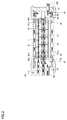
- first hollow fiber element and second hollow fiber element are serially loaded in one pressure vessel 1.
- the second embodiment is mainly different from the first embodiment in that it is a double element hollow fiber membrane module.
- the hollow fiber membrane module array group When the hollow fiber membrane module array group is used as a large plant, the number of hollow fiber membrane modules increases, the necessary piping becomes complicated, and the installation area of the hollow fiber membrane modules increases. It is desirable to make the equipment compact and efficient.
- One way to make the plant compact is to increase the ratio of hollow fiber membranes per hollow fiber membrane module by increasing the length of one hollow fiber membrane element to increase the membrane area per module. Conceivable. However, since the liquid flowing in the hollow portion of the hollow fiber membrane flows along the entire length from one end of the hollow portion to the other end, the pressure loss in the hollow portion increases as the hollow fiber membrane becomes longer. There is.
- Patent Document 1 WO 2004/069391
- Patent Document 2 Japanese Patent Application Laid-Open No. 2015-160157.
- the double-element hollow fiber membrane module has a pressure vessel per hollow fiber membrane element rather than a so-called single element hollow fiber membrane module in which one hollow fiber membrane element is loaded in one pressure vessel.
- the volume is reduced and the number of connecting pipes between hollow fiber membrane modules is also reduced, it has the advantage that the processing plant can be made compact.
- the first hollow fiber membrane element comprises a porous distribution pipe 21 having a plurality of holes 21a arranged in the center, a plurality of hollow fiber membranes 41 arranged in the periphery thereof, a porous distribution pipe 21 and a plurality And a resin wall 61 for fixing the hollow fiber membranes 41 at the both ends thereof.
- Each of the plurality of hollow fiber membranes 41 has an opening at its both ends.
- a porous distribution pipe 22 having a plurality of centrally disposed holes 22a, a plurality of hollow fiber membranes 42 disposed around the same, a porous distribution pipe 22 and a plurality of hollows And a resin wall 62 fixing the yarn membranes 42 at their ends.
- Each of the plurality of hollow fiber membranes 42 has an opening at its both ends.
- each hollow fiber membrane element in each hollow fiber membrane element, the opening of the hollow fiber membrane is connected to an independent supply port and discharge port corresponding to each hollow fiber membrane element. That is, each hollow fiber membrane element has DS supply ports 11a and 12a and discharge ports 11b and 12b which communicate with both the inside of the plurality of hollow fiber membranes 41 and 42 and the outside of the hollow fiber membrane module. .
- the inflow side openings 41a and 42a of the hollow fiber membranes 41 and 42 are respectively connected to the DS supply ports 11a and 12a, and the outflow side openings 41b and 42b are respectively connected to the DS discharge ports 11b and 12b.
- the bypass pipes 81 and 82 are pipes provided in the hollow fiber membrane element in the longitudinal direction, and have bypass pipe inlets 81 a and 82 a at the end on the outflow side opening 41 b or 42 b side of the hollow fiber membrane.
- the bypass pipe outlets 81b and 82b are provided at the end of the hollow fiber membrane on the inlet side openings 41a and 42a.
- the bypass pipe inlets 81a and 82a are respectively in communication with the flow paths 51a and 52a (see FIG. 5) inside the distributors 51 and 52, and the bypass pipe outlets 81b and 82b are flowed inside the distributors 53 and 54. It communicates with the passages 53a and 54a (see FIG. 6).
- the flow path 54c of the distributor 54 is sealed by the plug 55 so that the liquid can not pass therethrough.
- the middle connector 71 is a member connecting two hollow fiber membrane elements in the hollow fiber membrane module.
- the intermediate connector 71 includes a flow path passing between the porous distribution pipe 21 of the first hollow fiber membrane element and the bypass pipe 81, and the porous distribution pipe 22 of the second hollow fiber membrane element and the bypass pipe 82. And a flow passage for communicating with the flow passage passing therethrough.
- a thrust pipe 91 (see FIG. 7) is provided between the first hollow fiber membrane element and the wall member 13, and a thrust pipe 92 (FIG. 7) is provided between the second hollow fiber membrane element and the wall member 14. Reference) is installed.
- DS supplied from the DS supply ports 11a and 12a is introduced into the hollow fiber membranes 41 and 42 from the inflow side openings 41a and 42a of the hollow fiber membranes 41 and 42 in the hollow fiber membrane element. It flows in and flows out from the outflow side openings 41b and 42b on the other end side.
- the flowed-out DS passes from the flow paths 51b, 52b of the distributors 51, 52 through the flow paths 51a, 52a (see FIG. 5) and enters the bypass pipes from the bypass pipe inlets 81a, 82a of the bypass pipes 81, 82. It flows in each. Thereafter, the DS is taken out from the DS outlets 11b and 12b via the flow paths 53a and 54a (see FIG. 6) of the distributors 53 and 54 connected to the bypass pipe outlets 81b and 82b.
- the FS enters the gap between the porous distribution pipe 21 of the first hollow fiber membrane element and the bypass pipe 81 through the flow path 53c (see FIG. 6) outside the distributor 53 from the FS supply port 10a, It flows out from the hole 21 a and is supplied to the outer side 31 of the hollow fiber membrane 41.
- the remaining part of the FS passes through the intermediate connector 71 through the flow passage 51c (see FIG. 5) outside the distributor 51, and the second flow passage through the flow passage 52c (see FIG. 5) outside the distributor 52.
- the air enters the gap between the porous pipe 22 of the hollow fiber membrane element and the bypass pipe 82, flows out from the hole 22 a, and is supplied to the outer side 32 of the hollow fiber membrane 42.
- the FS passing through the outer side 31 of the hollow fiber membrane 41 of the first hollow fiber membrane element and the FS passing through the outer side 32 of the hollow fiber membrane 42 of the second hollow fiber membrane element join together and are taken out from the FS discharge port 10b Be
- both the DS supply port 11a and the DS discharge port 11b are one end side in the longitudinal direction of the first hollow fiber membrane element (opposite side to the second hollow fiber membrane element)
- both the DS supply port 12a and the DS discharge port 12b are provided on one end side in the longitudinal direction of the second hollow fiber membrane element (opposite to the first hollow fiber membrane element)
- the respective supply The port and the outlet communicate with the outside of the double element hollow fiber membrane module. Therefore, for example, when one hollow fiber membrane element is loaded or replaced, one end side of the hollow fiber membrane module in the longitudinal direction (one side of the rack into which the hollow fiber membrane module array group is incorporated) It is sufficient to work with only one, and work efficiency can be improved.
- each hollow fiber membrane element since the DS having passed through each hollow fiber membrane element is independently discharged from the DS outlet 11b or 12b, the performance of the two hollow fiber membrane elements should be evaluated separately. Can. As a result, since it is possible to determine and replace the hollow fiber membrane element replacement timing for each hollow fiber membrane element, it is possible to reduce costs and improve work efficiency.
- the DS flowing from one DS supply port flows into two hollow fiber membrane elements, and the first hollow fiber
- the DS since DS is supplied independently to two hollow fiber membrane elements, it is easy to uniformly control the supply amount of DS to the first hollow fiber membrane element and the second hollow fiber membrane element This makes it possible to express the performance of the element efficiently.
- one side (lower side) of the FS supply port 10a and one side (lower side) of the FS discharge port 10b are closed, but when connecting a plurality of hollow fiber membrane modules, they should be opened. Good.
- FS supply port 10a and FS discharge port 10b are provided in the outer peripheral part of the pressure vessel 1, it is not limited to such a form and can be changed suitably.
- the FS supply port 10 a and the FS discharge port 10 b may be provided in the wall members 13 and 14.
- the hollow fiber membrane module of the present invention is extremely useful, for example, in the field of producing energy using water treatment or concentration difference as a driving force. Specifically, it can be used for concentration and recovery of organic matter, volume reduction by concentration of waste water, desalination of seawater, etc. using a brine concentration method or the like.
- water treatment by the membrane separation method using the hollow fiber membrane module of the present invention is energy saving because it does not involve phase change as compared with conventional separation techniques such as distillation, and it is not accompanied by a state change of the substance. It can also be used in the field of food such as concentration of fruit juice, separation of brewer's yeast, separation of liquid mixture such as recovery of organic matter from industrial wastewater, concentration, etc.
Landscapes
- Chemical & Material Sciences (AREA)
- Chemical Kinetics & Catalysis (AREA)
- Engineering & Computer Science (AREA)
- Water Supply & Treatment (AREA)
- Separation Using Semi-Permeable Membranes (AREA)
Abstract
L'invention concerne un module à membrane à fibres creuses comprenant : un récipient sous pression; et au moins un élément à membrane à fibres creuses chargé dans le récipient sous pression. Chacun de l'au moins un élément à membrane à fibres creuses comprend : une pluralité de membranes à fibres creuses ayant des ouvertures aux deux extrémités; un tube de dérivation; et un orifice d'alimentation et un orifice de décharge disposés sur un côté d'extrémité dans une direction longitudinale. L'orifice d'alimentation communique avec des ouvertures côté entrée de la pluralité de membranes à fibres creuses. Le tube de dérivation est disposé dans une direction longitudinale du ou des éléments à membrane à fibres creuses. Le tube de dérivation comporte : un orifice d'entrée de tube de dérivation au niveau d'une extrémité du tube de dérivation sur le côté d'ouverture côté sortie de la membrane à fibres creuses; et un orifice de sortie de tube de dérivation au niveau d'une extrémité du tube de dérivation sur le côté d'ouverture côté entrée de la membrane à fibres creuses. Les ouvertures côté sortie de la pluralité de membranes à fibres creuses communiquent avec l'orifice d'entrée de tube de dérivation, et l'orifice de sortie de tube de dérivation communique avec l'orifice de décharge.
Priority Applications (3)
| Application Number | Priority Date | Filing Date | Title |
|---|---|---|---|
| CN201880049095.2A CN110958912B (zh) | 2017-07-28 | 2018-06-20 | 中空纤维膜组件 |
| US16/633,395 US11331630B2 (en) | 2017-07-28 | 2018-06-20 | Hollow fiber membrane module |
| EP18839296.3A EP3659694A4 (fr) | 2017-07-28 | 2018-06-20 | Module à membranes à fibres creuses |
Applications Claiming Priority (2)
| Application Number | Priority Date | Filing Date | Title |
|---|---|---|---|
| JP2017-146555 | 2017-07-28 | ||
| JP2017146555A JP6972737B2 (ja) | 2017-07-28 | 2017-07-28 | 中空糸膜モジュール |
Publications (1)
| Publication Number | Publication Date |
|---|---|
| WO2019021701A1 true WO2019021701A1 (fr) | 2019-01-31 |
Family
ID=65041047
Family Applications (1)
| Application Number | Title | Priority Date | Filing Date |
|---|---|---|---|
| PCT/JP2018/023497 Ceased WO2019021701A1 (fr) | 2017-07-28 | 2018-06-20 | Module à membranes à fibres creuses |
Country Status (5)
| Country | Link |
|---|---|
| US (1) | US11331630B2 (fr) |
| EP (1) | EP3659694A4 (fr) |
| JP (1) | JP6972737B2 (fr) |
| CN (1) | CN110958912B (fr) |
| WO (1) | WO2019021701A1 (fr) |
Cited By (2)
| Publication number | Priority date | Publication date | Assignee | Title |
|---|---|---|---|---|
| JPWO2021261324A1 (fr) * | 2020-06-25 | 2021-12-30 | ||
| EP4010288A4 (fr) * | 2019-08-09 | 2023-08-09 | Trevi Systems Inc. | Récipient à membrane d'osmose directe empilable doté d'orifices latéraux |
Families Citing this family (2)
| Publication number | Priority date | Publication date | Assignee | Title |
|---|---|---|---|---|
| JP7379835B2 (ja) * | 2019-03-14 | 2023-11-15 | 東洋紡エムシー株式会社 | 中空糸膜モジュール |
| JP7443761B2 (ja) * | 2019-12-25 | 2024-03-06 | 東洋紡エムシー株式会社 | 中空糸膜モジュール |
Citations (6)
| Publication number | Priority date | Publication date | Assignee | Title |
|---|---|---|---|---|
| JPS591618B2 (ja) | 1975-09-17 | 1984-01-13 | トヨタ自動車株式会社 | ブレ−キコントロ−ルバルブ |
| JPS638886B2 (fr) | 1982-04-01 | 1988-02-25 | Mitsubishi Electric Corp | |
| WO2004069391A1 (fr) | 2003-02-03 | 2004-08-19 | Toyo Boseki Kabushiki Kaisha | Module a membranes de fibres creuses et agencement de tels modules |
| JP4277147B2 (ja) | 1999-10-15 | 2009-06-10 | 東洋紡績株式会社 | 中空糸膜モジュールおよびその製造方法 |
| JP2013022543A (ja) * | 2011-07-25 | 2013-02-04 | Kubota Corp | 膜処理装置および膜モジュールの運転方法 |
| JP2015160157A (ja) | 2014-02-26 | 2015-09-07 | 東洋紡株式会社 | 中空糸膜モジュール |
Family Cites Families (17)
| Publication number | Priority date | Publication date | Assignee | Title |
|---|---|---|---|---|
| JPS60257819A (ja) * | 1984-06-04 | 1985-12-19 | Nippon Denso Co Ltd | 中空糸複合膜モジユ−ル及び除加湿装置 |
| JP2563855Y2 (ja) * | 1993-11-10 | 1998-02-25 | シーケーディ株式会社 | 除湿装置 |
| US5470469A (en) * | 1994-09-16 | 1995-11-28 | E. I. Du Pont De Nemours And Company | Hollow fiber cartridge |
| US5762789A (en) * | 1996-06-28 | 1998-06-09 | Millipore Corporation | Disposable membrane module with low-dead volume |
| JP3008886B2 (ja) | 1997-04-24 | 2000-02-14 | 東洋紡績株式会社 | 中空糸型選択透過膜モジュール |
| JPH11309331A (ja) * | 1998-04-30 | 1999-11-09 | Kitz Corp | 中空糸膜式ドライヤ |
| TW536424B (en) | 2001-09-05 | 2003-06-11 | Mitsubishi Rayon Co | Water-clean cartridge, water-cleaner, and washing method of water-cleaner |
| JP2003290633A (ja) * | 2002-04-03 | 2003-10-14 | Toyobo Co Ltd | 中空糸膜モジュール |
| DE60323694D1 (de) * | 2003-08-05 | 2008-10-30 | Toyo Boseki | Hohlfasermembranteilmodul und dieses enthaltende modul |
| US7338601B2 (en) * | 2004-12-10 | 2008-03-04 | Uop Llc | Membrane separation assemblies |
| JP5325453B2 (ja) * | 2008-05-02 | 2013-10-23 | Ckd株式会社 | 乾燥空気供給装置 |
| EP2213363B1 (fr) * | 2008-12-22 | 2013-04-17 | Seccua GmbH Deutschland | Dispositif de filtration à fibres creuses |
| EP2612685B1 (fr) * | 2010-08-19 | 2014-10-08 | Sorin Group Italia S.r.l. | Unité de traitement sanguin avec trajectoire de flux modifiée |
| EP2633898A4 (fr) | 2010-10-27 | 2014-10-01 | Toray Industries | Dispositif de filtration membranaire à fibres creuses et procédé de lavage d'un module membranaire à fibres creuses |
| JP2013212456A (ja) * | 2012-04-02 | 2013-10-17 | Jfe Engineering Corp | 中空糸膜モジュール |
| EP3061519B1 (fr) * | 2013-10-21 | 2021-04-21 | Toyobo Co., Ltd. | Élément de membrane à fibres creuses et module à membrane pour osmose directe |
| JP6565898B2 (ja) * | 2014-02-18 | 2019-08-28 | 東洋紡株式会社 | 中空糸膜エレメントおよび中空糸膜モジュール |
-
2017
- 2017-07-28 JP JP2017146555A patent/JP6972737B2/ja active Active
-
2018
- 2018-06-20 EP EP18839296.3A patent/EP3659694A4/fr not_active Withdrawn
- 2018-06-20 WO PCT/JP2018/023497 patent/WO2019021701A1/fr not_active Ceased
- 2018-06-20 US US16/633,395 patent/US11331630B2/en active Active
- 2018-06-20 CN CN201880049095.2A patent/CN110958912B/zh active Active
Patent Citations (7)
| Publication number | Priority date | Publication date | Assignee | Title |
|---|---|---|---|---|
| JPS591618B2 (ja) | 1975-09-17 | 1984-01-13 | トヨタ自動車株式会社 | ブレ−キコントロ−ルバルブ |
| JPS638886B2 (fr) | 1982-04-01 | 1988-02-25 | Mitsubishi Electric Corp | |
| JP4277147B2 (ja) | 1999-10-15 | 2009-06-10 | 東洋紡績株式会社 | 中空糸膜モジュールおよびその製造方法 |
| WO2004069391A1 (fr) | 2003-02-03 | 2004-08-19 | Toyo Boseki Kabushiki Kaisha | Module a membranes de fibres creuses et agencement de tels modules |
| JP4412486B2 (ja) | 2003-02-03 | 2010-02-10 | 東洋紡績株式会社 | 中空糸膜モジュールおよびそのモジュール配列群 |
| JP2013022543A (ja) * | 2011-07-25 | 2013-02-04 | Kubota Corp | 膜処理装置および膜モジュールの運転方法 |
| JP2015160157A (ja) | 2014-02-26 | 2015-09-07 | 東洋紡株式会社 | 中空糸膜モジュール |
Cited By (5)
| Publication number | Priority date | Publication date | Assignee | Title |
|---|---|---|---|---|
| EP4010288A4 (fr) * | 2019-08-09 | 2023-08-09 | Trevi Systems Inc. | Récipient à membrane d'osmose directe empilable doté d'orifices latéraux |
| US12390766B2 (en) | 2019-08-09 | 2025-08-19 | Trevi Systems Inc. | Stackable forward osmosis membrane vessel with side ports |
| JPWO2021261324A1 (fr) * | 2020-06-25 | 2021-12-30 | ||
| WO2021261324A1 (fr) * | 2020-06-25 | 2021-12-30 | 東洋紡株式会社 | Module de membrane à fibres creuses |
| JP7740239B2 (ja) | 2020-06-25 | 2025-09-17 | 東洋紡エムシー株式会社 | 中空糸膜モジュール |
Also Published As
| Publication number | Publication date |
|---|---|
| EP3659694A1 (fr) | 2020-06-03 |
| US11331630B2 (en) | 2022-05-17 |
| CN110958912A (zh) | 2020-04-03 |
| CN110958912B (zh) | 2022-07-01 |
| US20210069649A1 (en) | 2021-03-11 |
| EP3659694A4 (fr) | 2021-04-07 |
| JP2019025405A (ja) | 2019-02-21 |
| JP6972737B2 (ja) | 2021-11-24 |
Similar Documents
| Publication | Publication Date | Title |
|---|---|---|
| WO2019021701A1 (fr) | Module à membranes à fibres creuses | |
| US20160346739A1 (en) | Filtration apparatus | |
| WO2004069391A1 (fr) | Module a membranes de fibres creuses et agencement de tels modules | |
| JP2017025834A (ja) | 正浸透発電方法、および、それに用いる正浸透発電システム | |
| KR102567234B1 (ko) | 중공사막 엘리먼트, 중공사막 모듈 및 정침투수 처리 방법 | |
| EP3501627A1 (fr) | Module de membranes à fibres creuses plates et unité de séparation de membranes | |
| JP6264938B2 (ja) | 中空糸膜モジュール | |
| JP6862935B2 (ja) | 濃縮システムおよび濃縮方法 | |
| JP2015226864A (ja) | 正浸透用中空糸膜モジュール | |
| JP7352125B2 (ja) | 膜分離装置および膜分離方法 | |
| JP2003290632A (ja) | 中空糸膜モジュール | |
| JP6583416B2 (ja) | 中空糸膜エレメント、中空糸膜モジュールおよび正浸透水処理方法 | |
| JP2013212456A (ja) | 中空糸膜モジュール | |
| KR102774856B1 (ko) | 수처리 모듈용 텔레스코핑 방지 장치 | |
| JP7379835B2 (ja) | 中空糸膜モジュール | |
| JP7740239B2 (ja) | 中空糸膜モジュール | |
| JP7443761B2 (ja) | 中空糸膜モジュール | |
| WO2020022219A1 (fr) | Procédé de traitement par osmose directe inverse et dispositif de traitement par osmose directe | |
| WO2026004767A1 (fr) | Élément de membrane à fibres creuses et module de membrane à fibres creuses |
Legal Events
| Date | Code | Title | Description |
|---|---|---|---|
| 121 | Ep: the epo has been informed by wipo that ep was designated in this application |
Ref document number: 18839296 Country of ref document: EP Kind code of ref document: A1 |
|
| NENP | Non-entry into the national phase |
Ref country code: DE |
|
| WWE | Wipo information: entry into national phase |
Ref document number: 2018839296 Country of ref document: EP |