WO2019021702A1 - Dispositif d'imagerie - Google Patents
Dispositif d'imagerie Download PDFInfo
- Publication number
- WO2019021702A1 WO2019021702A1 PCT/JP2018/023502 JP2018023502W WO2019021702A1 WO 2019021702 A1 WO2019021702 A1 WO 2019021702A1 JP 2018023502 W JP2018023502 W JP 2018023502W WO 2019021702 A1 WO2019021702 A1 WO 2019021702A1
- Authority
- WO
- WIPO (PCT)
- Prior art keywords
- lens barrel
- optical axis
- axis direction
- holder
- lens
- Prior art date
- Legal status (The legal status is an assumption and is not a legal conclusion. Google has not performed a legal analysis and makes no representation as to the accuracy of the status listed.)
- Ceased
Links
Images

Classifications
-
- H—ELECTRICITY
- H04—ELECTRIC COMMUNICATION TECHNIQUE
- H04N—PICTORIAL COMMUNICATION, e.g. TELEVISION
- H04N23/00—Cameras or camera modules comprising electronic image sensors; Control thereof
- H04N23/50—Constructional details
- H04N23/55—Optical parts specially adapted for electronic image sensors; Mounting thereof
-
- G—PHYSICS
- G02—OPTICS
- G02B—OPTICAL ELEMENTS, SYSTEMS OR APPARATUS
- G02B7/00—Mountings, adjusting means, or light-tight connections, for optical elements
- G02B7/02—Mountings, adjusting means, or light-tight connections, for optical elements for lenses
-
- G—PHYSICS
- G02—OPTICS
- G02B—OPTICAL ELEMENTS, SYSTEMS OR APPARATUS
- G02B7/00—Mountings, adjusting means, or light-tight connections, for optical elements
- G02B7/02—Mountings, adjusting means, or light-tight connections, for optical elements for lenses
- G02B7/04—Mountings, adjusting means, or light-tight connections, for optical elements for lenses with mechanism for focusing or varying magnification
-
- G—PHYSICS
- G03—PHOTOGRAPHY; CINEMATOGRAPHY; ANALOGOUS TECHNIQUES USING WAVES OTHER THAN OPTICAL WAVES; ELECTROGRAPHY; HOLOGRAPHY
- G03B—APPARATUS OR ARRANGEMENTS FOR TAKING PHOTOGRAPHS OR FOR PROJECTING OR VIEWING THEM; APPARATUS OR ARRANGEMENTS EMPLOYING ANALOGOUS TECHNIQUES USING WAVES OTHER THAN OPTICAL WAVES; ACCESSORIES THEREFOR
- G03B17/00—Details of cameras or camera bodies; Accessories therefor
- G03B17/02—Bodies
Definitions
- One embodiment of the present invention relates to an imaging device and the like.
- focus adjustment is performed by adjusting the position of the lens relative to the position of the imaging element in the optical axis direction.
- various configurations are conventionally employed.
- the position of the lens in the optical axis direction is stabilized by urging the lens holding member toward the front side (subject side).
- the position of the lens barrel in the direction of the optical axis is fixed by pressing the lens barrel toward the image pickup device side at the time of assembly and adhering and fixing the lens barrel.
- the position of the lens may be shifted after assembly, and the focus may be shifted.
- the lens In the configuration described in Patent Document 1, when the user presses the lens from the front side, the lens may move to the rear side (the imaging device side).
- changes in temperature and humidity may cause degradation of the adhesive, which may shift the position of the lens barrel.
- One means of the present invention is A lens barrel (3) holding a lens; A holder (1) having an opening for holding the lens barrel; A substrate (5) on which an imaging device for receiving and imaging light transmitted through the lens is mounted; A spacer (4) fixed to the holder and disposed between the substrate and the lens barrel; And a biasing member (2) for biasing the lens barrel rearward in the optical axis direction, The position of the lens barrel in the optical axis direction changes in accordance with the contact position between the lens barrel and the spacer in the rotational direction. It is an imaging device.
- the lens barrel since the lens barrel is biased rearward in the optical axis direction, the lens barrel in the optical axis direction even when the user presses the lens or the lens barrel from the front side. Position does not shift. By this, it is possible to suppress out of focus at the time of use. Further, since the lens barrel is not fixed in position by the adhesive, the position of the lens barrel can be stabilized even if the temperature or humidity changes. Further, the position of the lens barrel in the direction of the optical axis can be changed by rotating the lens barrel or the like, whereby focus adjustment can be performed.
- the lens barrel (3) is rotatably held by the holder (1).
- the imaging apparatus having the above configuration, it is possible to perform focus adjustment by rotating the lens barrel.
- the lens barrel (3) is radially fitted with the holder (1) so as to be movable in the optical axis direction.
- the imaging apparatus having the above configuration, while the lens barrel is moved in the optical axis direction, focus adjustment is performed, while the movement of the lens barrel in the direction perpendicular to the optical axis is restricted to shift the optical axis. It can be set as suppression composition.
- the lens barrel (3) has a convex portion (33) at the rear in the optical axis direction
- the spacer has a cam surface (41) whose position in the optical axis direction changes in accordance with the contact position at a position where the spacer contacts the convex portion.
- the position of the lens barrel in the optical axis direction changes at the contact position between the convex portion and the cam surface, so the position of the lens barrel is adjusted with a relatively simple configuration. It becomes possible to perform focus adjustment. In addition, since the configuration is relatively simple, it is possible to suppress the manufacturing cost and the like.
- the spacer has a convex portion forward in the optical axis direction
- the lens barrel has a cam surface whose position in the optical axis direction changes in accordance with the contact position, at a position where the lens barrel contacts the convex portion.
- the position of the lens barrel in the optical axis direction changes at the contact position between the convex portion and the cam surface, so the position of the lens barrel is adjusted with a relatively simple configuration. It becomes possible to perform focus adjustment. In addition, since the configuration is relatively simple, it is possible to suppress the manufacturing cost and the like.
- the spacer (4) screw-engages with the holder (1) (43), and is diametrically engaged with the holder (44) at a position different from the screw-engaging position.
- the imaging apparatus having the above configuration, since the spacer is accurately held by the holder, the position of the lens barrel disposed in contact with the spacer can be further stabilized. This makes it possible to perform focus adjustment more accurately.
- FIG. 1 is an external perspective view of an imaging device as viewed from the front side.
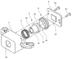
- FIG. 2 is an exploded perspective view of the imaging device as viewed from the front side.
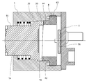
- FIG. 3 is a cross-sectional view of the imaging device.
- the image pickup apparatus is an apparatus such as a camera that picks up an image of a subject and acquires image data, and the lens mirror does not generate a focus shift even when the user presses the lens barrel to the rear side.
- One of the features is that the cylinder is held while being biased toward the rear side.
- the center position of the lens and the center position of the light incident on the imaging device is referred to as an “optical axis”.
- An imaging target located on the opposite side to the imaging element with respect to the lens is referred to as a "subject”.
- the direction in which the subject is positioned with respect to the imaging device is referred to as “front side” or “forward in the optical axis direction”, and the direction in which the imaging device is positioned relative to the subject is referred to as “rear side” or “rear in the optical axis direction”.
- FIG. 1 is an external perspective view of the imaging device of the present embodiment as viewed from the front side.
- FIG. 2 is an exploded perspective view of the imaging device of this embodiment as viewed from the front side.
- FIG. 3 is a cross-sectional view of the imaging device of the present embodiment.
- the imaging device of the present embodiment includes a holder 1, a compression spring 2, a lens barrel 3, a cam member 4, and a substrate 5.
- the holder 1 holds the compression spring 2, the lens barrel 3, and the cam member 4.
- the holder 1 is connected to the substrate 5 at the rear in the optical axis direction by connection screws 61 and 62.
- the holder 1 and the substrate 5 may be connected to each other using a connecting tool other than a screw, such as a rivet.
- the holder 1 and the substrate 5 may be connected by an adhesive, but it is preferable to use a connector such as a screw to facilitate disassembly after assembly.
- the holder 1 has an opening 1 a centered on the optical axis. As shown in FIG. 3, the opening 1 a is formed at a position inside the holder 1 in a combination of a plurality of cylindrical shapes having different inner diameters and extending in the optical axis direction.
- the compression spring 2, the lens barrel 3, and the cam member 4 are sequentially inserted and held in the opening 1 a from the rear in the optical axis direction.
- the lens barrel 3 is rotatably held inside the holder 1 with the lens barrel 3 fitted in a diameter.
- the cam member 4 is held inside the holder 1 in a screw-fitted state.
- a screw thread is formed on the inner side in the radial direction of the holder 1 and at a position facing the cam member 4, and the holder 1 and the cam member 4 are fitted by this screw thread.
- the rear surface of the holder 1 in the optical axis direction is fixed in contact with the substrate 5.
- the lens barrel 3 is formed of a first cylindrical portion 31 and a second cylindrical portion 32 each cylindrically extending in the optical axis direction, and holds one or more lenses including the lens 34 and other optical members.
- the first cylindrical portion 31 has an outer diameter smaller than that of the second cylindrical portion 32, and is located forward in the optical axis direction than the second cylindrical portion 32.
- the first cylindrical portion 31 and the second cylindrical portion 32 are integrally formed.
- the entire lens barrel 3 is inserted into the holder 1 (see FIG. 3 and the like) and held by the holder 1.
- the first cylindrical portion 31 of the lens barrel 3 is inserted to the front of the opening 1 a of the holder 1 in the optical axis direction.
- the front surface in the optical axis direction of the second cylindrical portion 32 of the lens barrel 3 abuts on the compression spring 2.
- the lens barrel 3 is biased rearward in the optical axis direction by the biasing force applied from the compression spring 2.
- the convex portion 33 protrudes rearward in the optical axis direction.
- the convex portion 33 partially protrudes along the outer peripheral surface of the second cylindrical portion 32.
- the convex portion 33 is in contact with a cam surface 41 formed on the front side of the cam member 4 in the optical axis direction.
- the lens barrel 3 is rotatable around the optical axis, and when the lens barrel 3 rotates, the convex portion 33 moves along the outer periphery of the lens barrel 3. When the convex portion 33 moves, the contact position between the convex portion 33 and the cam surface 41 of the cam member 4 changes.
- the cam surface 41 is inclined with respect to the surface perpendicular to the optical axis, when the contact position between the convex portion 33 and the cam surface 41 changes, the lens barrel in the optical axis direction The position of 3 changes.
- the positions of the lens barrel 3 and the lens (the distance between the imaging element 51 and the lens) with respect to the imaging element 51 in the optical axis direction change. To be done.
- Each lens including the lens 34 is an optical member which is formed of a transparent material such as glass or plastic and transmits light backward in the optical axis direction while refracting light from the front in the optical axis direction.
- the optical member includes a lens.
- the optical member held by the lens barrel 3 includes, in addition to the lens, a spacer, an aperture plate, an optical filter (all not shown), and the like.
- the spacer is a disk-shaped member having a suitable thickness in the optical axis direction, and adjusts the position of each lens in the optical axis direction.
- the spacer has an opening at the center including the optical axis.
- the aperture plate determines the outermost position of the passing light.
- An optical filter suppresses or blocks light of a predetermined wavelength.
- the optical filter includes, for example, an infrared cut filter that suppresses infrared light passing therethrough. The number of these optical members can be arbitrarily changed.
- the compression spring 2 is disposed between the holder 1 and the lens barrel 3 and is in contact with the surface of the holder 1 in the optical axis direction and the surface of the second cylindrical portion 32 of the lens barrel 3 in the optical axis direction. Contact.
- the compression spring 2 biases the holder 1 forward in the optical axis direction and rearwards the lens barrel 3 in the optical axis direction.
- the compression spring 2 is formed in an annular shape, and is disposed so that the first cylindrical portion 31 of the lens barrel 3 is located radially inward.
- the compression spring 2 may be replaced with another biasing member such as a leaf spring.
- the compression spring 2 is an example of the "biasing member" in the present invention.
- the cam member 4 is disposed between the lens barrel 3 and the substrate 5.
- the optical axis direction front of the cam member 4 is a cam surface 41 having an inclination in the circumferential direction.
- the cam surface 41 is inclined with respect to a plane perpendicular to the optical axis.
- the cam surface 41 is in contact with the convex portion 33 of the lens barrel 3.
- the cam member 4 is one structural example of the "spacer" in the present invention.
- the cam member 4 is in contact with the holder 1 at the front surface 42 in the optical axis direction. Further, on the rear side of the surface 42 in contact with the holder 1, a thread 43 is formed on the outer periphery of the cam member 4, and is screw-engaged with the thread formed on the inside of the holder 1. As described above, since the cam member 4 is screw-fitted while being in contact with the holder 1 in the optical axis direction, the cam member 4 is fixed in position without rattling with respect to the holder 1.
- the cam member 4 is in radial engagement with the holder 1 at a portion on the front side of the surface 42 in contact with the holder 1 and having a diameter smaller than the position where the screw thread 43 is formed.
- the cam member 4 is screwed with the holder 1 by the screw thread 43, the cam member 4 is diametrically engaged with the holder 1 on the front side (forward in the optical axis direction) than the screwing position. Therefore, the spacer 4 is held with high accuracy by the holder 1, so that the position in the optical axis direction of the lens barrel 3 whose position in the optical axis direction is fixed is stabilized by contacting the cam surface 41 of the spacer 4.
- the position at which the cam member 4 and the holder 1 are diametrically fitted does not necessarily have to be on the front side of the screwing position, but may be on the rear side.
- “diameter fitting” refers to a state of being fitted by being disposed in the radial direction with substantially no gap.
- the substrate 5 mounts the imaging device 51 and other electronic components (not shown). As shown in FIG. 3, the front surface of the substrate 5 in the optical axis direction is in contact with the rear surface of the holder 1 in the optical axis direction.
- the substrate 5 and the holder 1 are connected by connection screws 61 and 62.
- the front surface of the substrate 5 in the optical axis direction may be disposed with a gap from the holder 1 for position adjustment between the imaging device 51 and the lens held by the lens barrel 3 in the optical axis direction. good. In this case, the distance between the substrate 5 and the holder 1 is adjusted by the screwing amount of the connection screws 61 and 62 or the like.
- the image pickup device 51 is a photoelectric conversion device that receives light transmitted through a lens or the like held in the lens barrel 3 and converts the light into an electric signal and outputs the electric signal, and is, for example, a C-MOS sensor or a CCD.
- the imaging device 51 may be replaced with another imaging unit such as a film.
- the lens barrel 3 is biased rearward by the compression spring 2 instead of the optical axis direction, and the position of the lens barrel 3 in the optical axis direction is the optical axis. It changes according to the contact position of the lens barrel 3 and the cam member 4 in the rotation direction. Therefore, even when the user presses the lens 34 or the lens barrel 3 from the front side toward the rear side, the position of the lens barrel 3 in the optical axis direction does not shift. By this, it is possible to suppress out of focus at the time of use. Further, since the position of the lens barrel 3 is not fixed by the adhesive, the position of the lens barrel 3 can be stabilized even if the temperature or humidity changes. Further, by rotating the lens barrel 3, the position of the lens barrel 3 in the optical axis direction can be changed, whereby focus adjustment can be performed.
- the lens barrel 3 has the convex portion 33 projecting backward in the optical axis direction
- the cam member 4 has the cam surface 41 forward in the optical axis direction. It may be arranged reversely. That is, a cam surface may be formed on the rear side of the lens barrel 3 in the optical axis direction, and the cam member 4 may have a convex portion on the front side in the optical axis direction. Even with such a configuration, the contact position between the cam surface of the lens barrel 3 and the convex portion of the cam member 4 changes by rotating the lens barrel 3 around the optical axis. The position of the lens barrel 3 in the optical axis direction can be changed, and the same effect as that of the present embodiment can be obtained.
- the lens barrel 3 is rotatably held by the holder 1, it is possible to perform focus adjustment by rotating the lens barrel 3. it can.
- the lens barrel 3 is movably fitted in the optical axis direction with the holder 1, the focus adjustment is performed while moving the lens barrel 3 in the optical axis direction.
- the movement in the direction perpendicular to the optical axis can be restricted to suppress the deviation of the optical axis.
- an adhesive may be used to fix each member more reliably. Even in the case where an adhesive is used, in the imaging device of the present embodiment, the positions of the respective members are stabilized by the biasing force given by the compression spring 2 or the like, so even if the temperature or humidity changes, It is possible to suppress the displacement of the position of the member.
- the present invention is suitably used as an imaging device such as a camera in which the position of the optical axis is stable and the occurrence of focus shift is suppressed.
Landscapes
- Physics & Mathematics (AREA)
- General Physics & Mathematics (AREA)
- Optics & Photonics (AREA)
- Engineering & Computer Science (AREA)
- Multimedia (AREA)
- Signal Processing (AREA)
- Camera Bodies And Camera Details Or Accessories (AREA)
- Lens Barrels (AREA)
Abstract
L'invention concerne un dispositif d'imagerie équipé d'un barillet d'objectif pour maintenir une lentille, d'un support ayant une ouverture qui maintient le barillet d'objectif, d'un substrat sur lequel est monté un élément d'imagerie conçu pour l'imagerie par réception de la lumière ayant traversé la lentille, d'un séparateur qui est fixé au support et qui est positionné entre le substrat et le barillet d'objectif, et d'un élément inclinateur pour incliner le barillet d'objectif vers l'arrière en direction de l'axe optique, l'emplacement du barillet d'objectif par rapport à l'axe optique changeant en fonction de la position de contact dans la direction de rotation entre le barillet d'objectif et le séparateur.
Applications Claiming Priority (2)
| Application Number | Priority Date | Filing Date | Title |
|---|---|---|---|
| JP2017144640A JP2019028140A (ja) | 2017-07-26 | 2017-07-26 | 撮像装置 |
| JP2017-144640 | 2017-07-26 |
Publications (1)
| Publication Number | Publication Date |
|---|---|
| WO2019021702A1 true WO2019021702A1 (fr) | 2019-01-31 |
Family
ID=65040442
Family Applications (1)
| Application Number | Title | Priority Date | Filing Date |
|---|---|---|---|
| PCT/JP2018/023502 Ceased WO2019021702A1 (fr) | 2017-07-26 | 2018-06-20 | Dispositif d'imagerie |
Country Status (2)
| Country | Link |
|---|---|
| JP (1) | JP2019028140A (fr) |
| WO (1) | WO2019021702A1 (fr) |
Cited By (1)
| Publication number | Priority date | Publication date | Assignee | Title |
|---|---|---|---|---|
| CN115380233A (zh) * | 2020-04-10 | 2022-11-22 | 京瓷株式会社 | 拍摄装置 |
Citations (4)
| Publication number | Priority date | Publication date | Assignee | Title |
|---|---|---|---|---|
| JPS5778510A (en) * | 1980-11-05 | 1982-05-17 | Canon Inc | Focusing controller |
| JPS6451906U (fr) * | 1987-09-28 | 1989-03-30 | ||
| JP2008309812A (ja) * | 2006-04-13 | 2008-12-25 | Milestone Kk | 撮像レンズ繰出し装置及びその組み立て方法 |
| WO2016121165A1 (fr) * | 2015-01-30 | 2016-08-04 | 日本電産コパル株式会社 | Dispositif d'imagerie, dispositif optique muni de celui-ci, dispositif électronique muni de celui-ci, et procédé de production d'un dispositif d'imagerie |
-
2017
- 2017-07-26 JP JP2017144640A patent/JP2019028140A/ja active Pending
-
2018
- 2018-06-20 WO PCT/JP2018/023502 patent/WO2019021702A1/fr not_active Ceased
Patent Citations (4)
| Publication number | Priority date | Publication date | Assignee | Title |
|---|---|---|---|---|
| JPS5778510A (en) * | 1980-11-05 | 1982-05-17 | Canon Inc | Focusing controller |
| JPS6451906U (fr) * | 1987-09-28 | 1989-03-30 | ||
| JP2008309812A (ja) * | 2006-04-13 | 2008-12-25 | Milestone Kk | 撮像レンズ繰出し装置及びその組み立て方法 |
| WO2016121165A1 (fr) * | 2015-01-30 | 2016-08-04 | 日本電産コパル株式会社 | Dispositif d'imagerie, dispositif optique muni de celui-ci, dispositif électronique muni de celui-ci, et procédé de production d'un dispositif d'imagerie |
Cited By (1)
| Publication number | Priority date | Publication date | Assignee | Title |
|---|---|---|---|---|
| CN115380233A (zh) * | 2020-04-10 | 2022-11-22 | 京瓷株式会社 | 拍摄装置 |
Also Published As
| Publication number | Publication date |
|---|---|
| JP2019028140A (ja) | 2019-02-21 |
Similar Documents
| Publication | Publication Date | Title |
|---|---|---|
| JP5222815B2 (ja) | バックフォーカス調整機構を具えた撮像装置 | |
| US20070292121A1 (en) | Lens apparatus focus adjustment support device and focus adjusting method | |
| US9207427B2 (en) | Optical apparatus | |
| JP6747991B2 (ja) | 撮像装置 | |
| JP6967424B2 (ja) | 撮像装置 | |
| WO2019021702A1 (fr) | Dispositif d'imagerie | |
| US9563039B2 (en) | Lens apparatus and optical apparatus | |
| WO2018135453A1 (fr) | Dispositif d'imagerie | |
| JP5857536B2 (ja) | レンズ鏡筒のセンサ取付構造 | |
| KR101423693B1 (ko) | 광축 조절식 렌즈경통 | |
| JP2016130765A (ja) | レンズ鏡筒、光学機器、および、撮像装置 | |
| JP2003015005A (ja) | レンズ鏡胴 | |
| WO2019022104A1 (fr) | Dispositif d'imagerie | |
| JP2011133592A (ja) | レンズ鏡筒 | |
| JP6667424B2 (ja) | 撮像装置 | |
| JP2010276990A (ja) | 撮像装置のバックフォーカス調整機構 | |
| JP6761220B2 (ja) | 撮像装置 | |
| JP2022065957A5 (fr) | ||
| JP2019028416A (ja) | 撮像装置 | |
| JP2020016829A (ja) | レンズ保持機構及び撮像装置 | |
| JP2019020529A (ja) | 撮像装置 | |
| JP2021047347A (ja) | レンズ鏡筒 | |
| JP2010026322A (ja) | レンズ鏡筒 | |
| US12443004B2 (en) | Optical apparatus and image pickup apparatus | |
| JP2019045546A (ja) | 撮像装置 |
Legal Events
| Date | Code | Title | Description |
|---|---|---|---|
| 121 | Ep: the epo has been informed by wipo that ep was designated in this application |
Ref document number: 18838073 Country of ref document: EP Kind code of ref document: A1 |
|
| NENP | Non-entry into the national phase |
Ref country code: DE |
|
| 122 | Ep: pct application non-entry in european phase |
Ref document number: 18838073 Country of ref document: EP Kind code of ref document: A1 |