WO2019021723A1 - タイヤ - Google Patents
タイヤ Download PDFInfo
- Publication number
- WO2019021723A1 WO2019021723A1 PCT/JP2018/024227 JP2018024227W WO2019021723A1 WO 2019021723 A1 WO2019021723 A1 WO 2019021723A1 JP 2018024227 W JP2018024227 W JP 2018024227W WO 2019021723 A1 WO2019021723 A1 WO 2019021723A1
- Authority
- WO
- WIPO (PCT)
- Prior art keywords
- groove
- width direction
- width
- tire
- groove portion
- Prior art date
- Legal status (The legal status is an assumption and is not a legal conclusion. Google has not performed a legal analysis and makes no representation as to the accuracy of the status listed.)
- Ceased
Links
Images



Classifications
-
- B—PERFORMING OPERATIONS; TRANSPORTING
- B60—VEHICLES IN GENERAL
- B60C—VEHICLE TYRES; TYRE INFLATION; TYRE CHANGING; CONNECTING VALVES TO INFLATABLE ELASTIC BODIES IN GENERAL; DEVICES OR ARRANGEMENTS RELATED TO TYRES
- B60C11/00—Tyre tread bands; Tread patterns; Anti-skid inserts
- B60C11/03—Tread patterns
- B60C11/13—Tread patterns characterised by the groove cross-section, e.g. for buttressing or preventing stone-trapping
- B60C11/1307—Tread patterns characterised by the groove cross-section, e.g. for buttressing or preventing stone-trapping with special features of the groove walls
-
- B—PERFORMING OPERATIONS; TRANSPORTING
- B60—VEHICLES IN GENERAL
- B60C—VEHICLE TYRES; TYRE INFLATION; TYRE CHANGING; CONNECTING VALVES TO INFLATABLE ELASTIC BODIES IN GENERAL; DEVICES OR ARRANGEMENTS RELATED TO TYRES
- B60C11/00—Tyre tread bands; Tread patterns; Anti-skid inserts
- B60C11/03—Tread patterns
- B60C11/12—Tread patterns characterised by the use of narrow slits or incisions, e.g. sipes
- B60C11/1272—Width of the sipe
- B60C11/1281—Width of the sipe different within the same sipe, i.e. enlarged width portion at sipe bottom or along its length
-
- B—PERFORMING OPERATIONS; TRANSPORTING
- B60—VEHICLES IN GENERAL
- B60C—VEHICLE TYRES; TYRE INFLATION; TYRE CHANGING; CONNECTING VALVES TO INFLATABLE ELASTIC BODIES IN GENERAL; DEVICES OR ARRANGEMENTS RELATED TO TYRES
- B60C11/00—Tyre tread bands; Tread patterns; Anti-skid inserts
- B60C11/01—Shape of the shoulders between tread and sidewall, e.g. rounded, stepped or cantilevered
-
- B—PERFORMING OPERATIONS; TRANSPORTING
- B60—VEHICLES IN GENERAL
- B60C—VEHICLE TYRES; TYRE INFLATION; TYRE CHANGING; CONNECTING VALVES TO INFLATABLE ELASTIC BODIES IN GENERAL; DEVICES OR ARRANGEMENTS RELATED TO TYRES
- B60C11/00—Tyre tread bands; Tread patterns; Anti-skid inserts
- B60C11/03—Tread patterns
- B60C11/12—Tread patterns characterised by the use of narrow slits or incisions, e.g. sipes
- B60C11/1204—Tread patterns characterised by the use of narrow slits or incisions, e.g. sipes with special shape of the sipe
- B60C11/1218—Three-dimensional shape with regard to depth and extending direction
-
- B—PERFORMING OPERATIONS; TRANSPORTING
- B60—VEHICLES IN GENERAL
- B60C—VEHICLE TYRES; TYRE INFLATION; TYRE CHANGING; CONNECTING VALVES TO INFLATABLE ELASTIC BODIES IN GENERAL; DEVICES OR ARRANGEMENTS RELATED TO TYRES
- B60C11/00—Tyre tread bands; Tread patterns; Anti-skid inserts
- B60C11/03—Tread patterns
- B60C11/12—Tread patterns characterised by the use of narrow slits or incisions, e.g. sipes
- B60C11/1236—Tread patterns characterised by the use of narrow slits or incisions, e.g. sipes with special arrangements in the tread pattern
-
- B—PERFORMING OPERATIONS; TRANSPORTING
- B60—VEHICLES IN GENERAL
- B60C—VEHICLE TYRES; TYRE INFLATION; TYRE CHANGING; CONNECTING VALVES TO INFLATABLE ELASTIC BODIES IN GENERAL; DEVICES OR ARRANGEMENTS RELATED TO TYRES
- B60C11/00—Tyre tread bands; Tread patterns; Anti-skid inserts
- B60C11/03—Tread patterns
- B60C11/12—Tread patterns characterised by the use of narrow slits or incisions, e.g. sipes
- B60C11/1272—Width of the sipe
-
- B—PERFORMING OPERATIONS; TRANSPORTING
- B60—VEHICLES IN GENERAL
- B60C—VEHICLE TYRES; TYRE INFLATION; TYRE CHANGING; CONNECTING VALVES TO INFLATABLE ELASTIC BODIES IN GENERAL; DEVICES OR ARRANGEMENTS RELATED TO TYRES
- B60C11/00—Tyre tread bands; Tread patterns; Anti-skid inserts
- B60C11/03—Tread patterns
- B60C11/13—Tread patterns characterised by the groove cross-section, e.g. for buttressing or preventing stone-trapping
- B60C11/1307—Tread patterns characterised by the groove cross-section, e.g. for buttressing or preventing stone-trapping with special features of the groove walls
- B60C11/1315—Tread patterns characterised by the groove cross-section, e.g. for buttressing or preventing stone-trapping with special features of the groove walls having variable inclination angles, e.g. warped groove walls
-
- B—PERFORMING OPERATIONS; TRANSPORTING
- B60—VEHICLES IN GENERAL
- B60C—VEHICLE TYRES; TYRE INFLATION; TYRE CHANGING; CONNECTING VALVES TO INFLATABLE ELASTIC BODIES IN GENERAL; DEVICES OR ARRANGEMENTS RELATED TO TYRES
- B60C19/00—Tyre parts or constructions not otherwise provided for
- B60C19/002—Noise damping elements provided in the tyre structure or attached thereto, e.g. in the tyre interior
-
- B—PERFORMING OPERATIONS; TRANSPORTING
- B60—VEHICLES IN GENERAL
- B60C—VEHICLE TYRES; TYRE INFLATION; TYRE CHANGING; CONNECTING VALVES TO INFLATABLE ELASTIC BODIES IN GENERAL; DEVICES OR ARRANGEMENTS RELATED TO TYRES
- B60C11/00—Tyre tread bands; Tread patterns; Anti-skid inserts
- B60C11/03—Tread patterns
- B60C2011/0337—Tread patterns characterised by particular design features of the pattern
- B60C2011/0339—Grooves
- B60C2011/0341—Circumferential grooves
-
- B—PERFORMING OPERATIONS; TRANSPORTING
- B60—VEHICLES IN GENERAL
- B60C—VEHICLE TYRES; TYRE INFLATION; TYRE CHANGING; CONNECTING VALVES TO INFLATABLE ELASTIC BODIES IN GENERAL; DEVICES OR ARRANGEMENTS RELATED TO TYRES
- B60C11/00—Tyre tread bands; Tread patterns; Anti-skid inserts
- B60C11/03—Tread patterns
- B60C2011/0337—Tread patterns characterised by particular design features of the pattern
- B60C2011/0339—Grooves
- B60C2011/0341—Circumferential grooves
- B60C2011/0353—Circumferential grooves characterised by width
-
- B—PERFORMING OPERATIONS; TRANSPORTING
- B60—VEHICLES IN GENERAL
- B60C—VEHICLE TYRES; TYRE INFLATION; TYRE CHANGING; CONNECTING VALVES TO INFLATABLE ELASTIC BODIES IN GENERAL; DEVICES OR ARRANGEMENTS RELATED TO TYRES
- B60C11/00—Tyre tread bands; Tread patterns; Anti-skid inserts
- B60C11/03—Tread patterns
- B60C2011/0337—Tread patterns characterised by particular design features of the pattern
- B60C2011/0339—Grooves
- B60C2011/0358—Lateral grooves, i.e. having an angle of 45 to 90 degees to the equatorial plane
- B60C2011/0365—Lateral grooves, i.e. having an angle of 45 to 90 degees to the equatorial plane characterised by width
-
- B—PERFORMING OPERATIONS; TRANSPORTING
- B60—VEHICLES IN GENERAL
- B60C—VEHICLE TYRES; TYRE INFLATION; TYRE CHANGING; CONNECTING VALVES TO INFLATABLE ELASTIC BODIES IN GENERAL; DEVICES OR ARRANGEMENTS RELATED TO TYRES
- B60C11/00—Tyre tread bands; Tread patterns; Anti-skid inserts
- B60C11/03—Tread patterns
- B60C2011/0337—Tread patterns characterised by particular design features of the pattern
- B60C2011/0339—Grooves
- B60C2011/0374—Slant grooves, i.e. having an angle of about 5 to 35 degrees to the equatorial plane
- B60C2011/0376—Slant grooves, i.e. having an angle of about 5 to 35 degrees to the equatorial plane characterised by width
-
- B—PERFORMING OPERATIONS; TRANSPORTING
- B60—VEHICLES IN GENERAL
- B60C—VEHICLE TYRES; TYRE INFLATION; TYRE CHANGING; CONNECTING VALVES TO INFLATABLE ELASTIC BODIES IN GENERAL; DEVICES OR ARRANGEMENTS RELATED TO TYRES
- B60C11/00—Tyre tread bands; Tread patterns; Anti-skid inserts
- B60C11/03—Tread patterns
- B60C11/12—Tread patterns characterised by the use of narrow slits or incisions, e.g. sipes
- B60C11/1236—Tread patterns characterised by the use of narrow slits or incisions, e.g. sipes with special arrangements in the tread pattern
- B60C2011/1245—Tread patterns characterised by the use of narrow slits or incisions, e.g. sipes with special arrangements in the tread pattern being arranged in crossing relation, e.g. sipe mesh
-
- B—PERFORMING OPERATIONS; TRANSPORTING
- B60—VEHICLES IN GENERAL
- B60C—VEHICLE TYRES; TYRE INFLATION; TYRE CHANGING; CONNECTING VALVES TO INFLATABLE ELASTIC BODIES IN GENERAL; DEVICES OR ARRANGEMENTS RELATED TO TYRES
- B60C11/00—Tyre tread bands; Tread patterns; Anti-skid inserts
- B60C11/03—Tread patterns
- B60C11/12—Tread patterns characterised by the use of narrow slits or incisions, e.g. sipes
- B60C11/1236—Tread patterns characterised by the use of narrow slits or incisions, e.g. sipes with special arrangements in the tread pattern
- B60C2011/1254—Tread patterns characterised by the use of narrow slits or incisions, e.g. sipes with special arrangements in the tread pattern with closed sipe, i.e. not extending to a groove
-
- B—PERFORMING OPERATIONS; TRANSPORTING
- B60—VEHICLES IN GENERAL
- B60C—VEHICLE TYRES; TYRE INFLATION; TYRE CHANGING; CONNECTING VALVES TO INFLATABLE ELASTIC BODIES IN GENERAL; DEVICES OR ARRANGEMENTS RELATED TO TYRES
- B60C11/00—Tyre tread bands; Tread patterns; Anti-skid inserts
- B60C11/03—Tread patterns
- B60C11/12—Tread patterns characterised by the use of narrow slits or incisions, e.g. sipes
- B60C11/1259—Depth of the sipe
- B60C2011/1268—Depth of the sipe being different from sipe to sipe
Definitions
- the present invention relates to a tire.
- the tire noise around 1000 Hz is mainly due to air column resonance.
- the air column resonance noise is a noise generated by the resonance of air in the pipe, which is surrounded by the circumferential groove extending continuously in the circumferential direction of the tread surface, and is about 800 to 1200 Hz in a general passenger car. It is often observed.
- Such air column resonance noise accounts for most of the noise generated from the tire because the peak level is high and the frequency band is wide.
- a side branch type resonator having a longitudinal groove and a lateral groove is provided on a rib-like land portion partitioned by a plurality of circumferential grooves.
- An air chamber opened to the surface of the land portion at a position separated from the circumferential groove in the land portion, and one or more narrowing necks connecting the air chamber to the circumferential groove;
- a device provided with a Helmholtz-type resonator (Japanese Patent Application Laid-Open No. 2000-147118).
- an object of this invention is to provide the tire which can suppress the partial abrasion in a tread, reducing air column resonance noise.
- the tire according to the present invention has a shoulder which is divided into at least one circumferential groove continuously extending in the circumferential direction of the tire, and the circumferential groove on the outermost side in the tire width direction and the tread contact end on the tread tread surface.
- the shoulder land portion has a width direction groove extending in the width direction of the tire and communicating the circumferential groove with the tread contact end, and the width direction groove includes the land portion.
- a first width direction groove portion communicating with the circumferential direction groove and a second width direction groove portion adjacent to and continuous with the tread ground end side of the first width direction groove portion, the first width direction groove portion
- the circumferential groove having a narrow groove portion in which the opening width in the tread surface is smaller than the groove width on the groove bottom side in at least a partial region in the extending direction of the first width direction groove portion.
- Respective groove widths of the first width direction groove portion and the second width direction groove portion And satisfies a relational expression "circumferential grooves in groove width> groove width> groove width of the second width direction groove portion of the first width direction groove portion".
- the term “tread tread surface” refers to a tire that is assembled to a rim and filled with a predetermined internal pressure and is rolled in a state of loading a maximum load (hereinafter referred to as “maximum load state”). In this case, it means the outer circumferential surface over the entire circumference of the tire that comes into contact with the road surface, and "tread ground contact end” means the tire width direction end of the tread surface.
- the “reference state” described later in the present specification refers to a state in which the tire is assembled to the rim, filled with a predetermined internal pressure, and not loaded.
- rim is an industrial standard effective for the area where tires are produced and used, and in Japan, JATMA (Japan Automobile Tire Association) JATMA YEAR BOOK, in Europe ETRTO (The European Tire and Rim Technical Standard rims in applicable sizes (Measuring Rim, STANDARDS MANUAL at ETRTO, described in Organizations' STANDARDS MANUAL, and in the United States, TRA (The Tire and Rim Association, Inc.) YEAR BOOK etc. in the United States, or in the future) In the TRA's YEAR BOOK, it refers to Design Rim) (ie, the "rim” above includes in addition to the current size a size that may be included in the above industry standard in the future.
- predetermined internal pressure refers to the air pressure (maximum air pressure) corresponding to the maximum load capacity of a single wheel in application size and ply rating described in the above-mentioned JATMA YEAR BOOK etc.
- predetermined internal pressure refers to the air pressure (maximum air pressure) corresponding to the maximum load capacity defined for each vehicle on which the tire is mounted.
- maximum load load shall mean the load corresponding to the above-mentioned maximum load capacity.
- the “groove width of the circumferential groove” refers to the length measured in the above-mentioned reference direction in the direction orthogonal to the extending direction of the circumferential groove.
- the groove width of the first width direction groove portion refers to the length measured in the above-mentioned reference direction in the direction orthogonal to the extending direction of the circumferential groove.
- the groove width of the first width direction groove portion refers to the length measured in the above-mentioned reference direction in the direction orthogonal to the extending direction of the circumferential groove.
- groove width of circumferential groove “groove width of first width direction groove portion”, “groove width of second width direction groove portion”, and “groove width of third width direction groove portion” described later
- the groove width changes along the depth direction of the groove and / or the extending direction of the groove, with the maximum width unless otherwise specified conditions such as the measurement position in the depth direction or the extending direction
- the groove width is taken.
- the dimensions and the like of the respective elements such as grooves are measured in the reference state (the dimensions and the like on the tread surface of the respective elements are on the developed view of the tread surface in the reference state).
- “sipe” refers to a narrow groove having a width such that at least a portion of the tire is closed when the tire is rolled under a maximum load state.
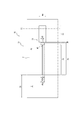
- FIG. 1 is a partially developed view schematically showing a part of a tread surface of a tire according to an embodiment of the present invention. It is a partial expanded view which expands a part of tread surface of Drawing 1 typically, and is shown typically.
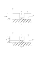
- (A) is a cross-sectional view taken along the line II of FIG. 2
- (b) is a cross-sectional view taken along the line II-II of FIG.
- FIG. 5 is a partially developed view schematically showing an enlarged part of a tread surface of a tire according to another embodiment of the present invention. It is a partially developed view schematically showing a part of a tread surface of a tire according to still another embodiment of the present invention in an enlarged manner.
- FIG. 10 is a partial development view schematically showing a part of a tread surface of a tire according to still another embodiment of the present invention. It is a partially developed view schematically showing a part of a tread surface of a tire according to still another embodiment of the present invention in an enlarged manner.
- (A) is a cross-sectional view taken along the line III-III in FIG. 8, and (b) is a modified example thereof.
- FIG. 9 is a partially developed view schematically showing an enlarged part of a tread surface to explain the positional relationship of grooves and the like in the tire of FIG. 8.
- FIG. 1 is a partially developed view schematically showing a tread surface T of a tread 1 of a tire 10 according to an embodiment of the present invention.
- the tire 10 extends continuously in the tire circumferential direction on the tread surface T of the tread 1 (in the illustrated example, along the tire circumferential direction, that is, in the tire circumferential direction at an angle of 0 ° with respect to the tire circumferential direction
- At least one (four in the illustrated example) circumferential grooves 2 extending continuously, and including the tire equatorial plane TC by the four circumferential grooves 2 and both tread contact edges TE
- the center land portion 4C, two middle land portions 4M adjacent to both center sides of the center land portion 4C in the tire width direction via the circumferential groove 2, and the center land portion 4M in the tire width direction both sides circumferentially
- Two shoulder lands 4S adjacent to each other through the groove 2 are sectioned.
- the circumferential groove 2 in this embodiment is a linear groove continuously extending in the tire circumferential direction along the tire circumferential direction
- the circumferential groove 2 is in the tire circumferential direction. It is also possible to form a zigzag or wave-like groove that extends continuously in the circumferential direction of the tire while being inclined with respect to (tire equatorial plane TC).
- at least one circumferential groove 2 may be provided, and in the present embodiment there are four, but the number is not limited to this and it is preferable to have a plurality. In the case of plural, two, three or five or more may be used.
- the tire 10 according to the present embodiment is divided into at least one circumferential groove 2 continuously extending in the circumferential direction of the tire, and the circumferential groove 2 and the tread contact end TE in the tread surface T. And the land portion 4S.
- the tire 10 which concerns on this embodiment is a pneumatic radial tire for passenger cars
- this invention is applicable also to the tire of the other kind which has a request
- the internal structure of the tire is not particularly limited.
- a plurality of shoulder land portions 4S in the present embodiment extend in the tire width direction and communicate the circumferential groove 2 with the tread contact end TE, and are separated from each other in the tire circumferential direction in the present embodiment (in the illustrated example Of which three are shown)), and a plurality of block-like land portions are formed in the tire circumferential direction on the shoulder land portion 4S by the width direction grooves 3. .
- the widthwise groove 3 in the present embodiment is inclined with respect to the tire width direction and extends in an arc shape between the circumferential groove 2 and the tread contact end TE.
- the width direction groove according to the present invention is not limited to this, and the width direction groove can be extended along the tire width direction, or the width direction groove can be made linear.
- the width direction groove 3 should just have a tire width direction component.
- the width direction grooves 3 in both shoulder land portions 4S are points substantially symmetrical to each other with respect to the tire equatorial plane TC, and a point centered on any one point on the tire equatorial plane TC in the figure. It is arranged symmetrically. That is, in the shoulder land portion 4S on one side (right side in the drawing) of the tire equatorial plane TC, the width direction groove 3 has an arc shape having the center of the arc on one side (upper side in the drawing) of the width direction groove 3 in the tire circumferential direction.
- the widthwise groove 3 has a center of arc on the other side (lower side in the drawing) of the widthwise groove 3 of the tire equatorial plane TC. It extends in an arc shape.
- the tire 10 according to the present embodiment is a tire regardless of the rotational direction of the tire and the mounting direction to the vehicle.
- the widthwise groove 3 according to the present invention can be either line symmetrical or point symmetrical with respect to the tire equatorial plane TC, and is neither linear symmetrical nor point symmetrical with respect to the tire equatorial plane TC May be
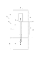
- FIG. 2 is a partially developed view schematically showing a part of the tread surface T shown in FIG. 1 in an enlarged manner.
- all width direction grooves 3 in both shoulder land portions 4S have the same configuration, but in FIG. 2, a plurality of grooves formed on the tread surface T of the tread 1 of FIG.
- One of the width direction grooves 3 is enlarged and schematically shown.
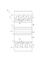
- 3 (a) and 3 (b) are cross-sectional views taken along line II and line II-II in FIG. 2, respectively.
- the width direction groove 3 is orthogonal to the extending direction of the width direction groove 3 Shows the cross section of the plane to be
- the width direction groove 3 which concerns on this embodiment inclines with respect to the tire width direction and extends in circular arc shape as above-mentioned, here, for description, this width direction groove 3 is a tire width. It is schematically shown as extending linearly along the direction.
- the widthwise groove 3 in the present embodiment is narrower than the circumferential groove 2 as shown in FIG. 2, and a first widthwise groove portion 3A communicating with the circumferential groove 2 and the first widthwise direction A second width direction groove portion 3B adjacent to the tread ground contact end TE side of the groove portion 3A and narrower than the first width direction groove portion 3A, and a tread ground end TE of the second width direction groove portion 3B And a third width direction groove portion 3C communicating with the tread ground contact end TE.
- the opening width W2b at the tread surface T is the groove width W2a at the groove bottom side in at least a partial region of the extension direction of the first width direction groove portion 3A.
- the narrowing groove 3a is provided smaller than the groove width W2 of the first widthwise groove portion 3A. That is, although the first width direction groove portion 3A in the present embodiment has the same groove width over the entire length of the first width direction groove portion 3A on the groove bottom side, the first width direction groove at the open end position In at least a partial area of the extending direction of the portion 3A, there is an area where the opening width to the tread surface T is relatively small.
- the region is referred to as a constricted groove 3a.
- the groove wall 3w on the groove bottom side of the constricted groove 3a is indicated by a broken line
- the open end of the tread tread T of the constricted groove 3a is indicated by a solid line.
- the narrowing groove portion 3a is a region extending substantially the entire length of the first widthwise groove portion 3A, more specifically, from the end on the circumferential groove 2 side of the first widthwise groove portion 3A. It extends continuously in a region up to a position of 90% or more of the extension length of the first widthwise groove portion 3A. That is, the extension length of the narrowing groove portion 3a is 90% or more of the extension length of the first width direction groove portion 3A.
- the narrowing groove portion 3a may be formed in at least a partial region of the extending direction of the first width direction groove portion 3A, and the extending length is not limited.
- the extension length of the narrowing groove portion 3a is preferably 50% or more of the extension length of the first width direction groove portion 3A, more preferably 60% or more, 70% or more, further preferably 80% or more, and 100% most preferable. However, it may be less than 50%.
- the constriction groove 3a may be continuous or discontinuous, and may be divided into, for example, two, three or more and discontinuously extended.
- the narrowing groove 3a in the present embodiment is a cross section of the narrowing groove 3a taken along a plane perpendicular to the extending direction of the width direction groove 3. While having a relatively wide groove width W2a (in the present embodiment, equal to the groove width W2 of the first width direction groove portion 3A), at the open end position of the narrowed groove portion 3a in the tread surface T, The opening width W2b is narrower than the groove width W2a.
- a groove wall 3 v of a portion other than the narrow groove portion 3 a of the first width direction groove portion 3 A is indicated by a broken line.
- the narrow groove portion 3a in the present embodiment has a groove bottom side region R1 having a relatively wide groove width W2a on the groove bottom side of the narrow groove portion 3a, and a tire of the groove bottom side region R1. And an open end region R2 having a width (equal to the opening width W2b in this embodiment) narrower than the groove width W2a of the groove bottom region R1 disposed radially outward and extending to the tread surface T. There is.
- the groove width W2a of the groove bottom side region R1 is the groove width of the portion of the first width direction groove portion 3A other than the narrowing groove portion 3a (the groove width W2 of the first width direction groove portion 3A)
- the groove width W2a of the groove bottom side region R1 can be made smaller and / or larger than the groove width of the portion of the first widthwise groove portion 3A other than the narrowing groove portion 3a.
- the opening end region R2 in the present embodiment extends from the tire radial direction inner end to the outer end of the opening end region R2 with a constant groove width.
- the opening end region R2 is located substantially on the groove width center of the constricted groove 3a, and extends along the normal direction of the tread surface T.
- the opening end region R2 in the present embodiment has a constant groove width over the tire radial direction (equal to the opening width W2b over the tire radial direction), but the groove width is the inner side of the tire radial direction. It may be changed so as to decrease or increase from the outside to the outside. However, it is preferable that the groove width in the opening end region R2 be constant in the tire radial direction because the falling of the block of the shoulder land portion 4S can be suppressed when the vehicle is traveling.
- the cross-sectional shape of the narrowing groove portion 3a is not limited to the above-described example, and may be, for example, a triangular shape whose apex on the tread tread surface T side is an apex. It may be a symmetrical pentagonal shape or the like with the R2 side as an apex.
- the second widthwise groove portion 3B is a cross section taken along a plane perpendicular to the extending direction of the widthwise groove 3 of the second widthwise groove portion 3B in this embodiment.
- a groove width W3 that is narrower than the groove width W2 of the widthwise groove 3 is provided across the tire radial direction.
- the groove width W3 of the second width direction groove portion 3B in the present embodiment is constant over the tire radial direction, the groove width W3 gradually decreases or gradually increases from the inner side to the outer side of the tire radial direction. May be changed to Further, the groove depth D3 of the second widthwise groove portion 3B in the present embodiment is equal to the groove depth D1 of the first widthwise groove portion 3A (that is, the groove depth of the narrowed groove portion 3a).
- the groove depth D3 of the directional groove portion 3B can be made shallower than the groove depth D1 of the first widthwise groove portion 3A. In this example, the groove depth D1 of the first widthwise groove portion 3A and the groove depth D3 of the second widthwise groove portion 3B are constant.
- the tire 10 in the tire 10 according to the present embodiment, at least one (four in the present embodiment) circumferential grooves 2 extending continuously in the tire circumferential direction on the tread tread surface T, and the outermost in the tire width direction
- the shoulder land portion 4S is divided by the circumferential groove 2 and the tread ground contact end TE, and the shoulder land portion 4S extends in the tire width direction and communicates the circumferential groove 2 with the tread ground end TE.
- a first width direction groove portion 3A communicating with the circumferential direction groove 2 and having a width direction groove 3 and a first width direction groove portion 3A adjacent to the tread ground end TE side of the first width direction groove portion 3A
- the first widthwise groove portion 3A has a groove bottom with an opening width W2b at the tread surface T in at least a part of the area in the extension direction of the first widthwise groove portion 3A.
- Each of the groove widths W1, W2, and W3 of the circumferential groove 2, the first width direction groove portion 3A, and the second width direction groove portion 3B has the following relationship. Formula (1) is satisfied. Groove width W1 of circumferential groove 2> Groove width W2 of first width direction groove portion 3A> Groove width W3 of second width direction groove portion 3B (1)
- the widthwise groove 3 provided in the shoulder land portion 4S which communicates the circumferential groove 2 with the tread ground contact end TE, includes the first widthwise groove portion 3A having the narrowed groove portion 3a and A two-width direction groove portion 3B is provided, and further, the groove width W1 of the circumferential direction groove 2, the groove width W2 of the first width direction groove portion 3A, and the groove width W3 of the second width direction groove portion 3B Since 1) is satisfied, it is possible to suppress uneven wear in the tread while reducing air column resonance noise.
- the vehicle is provided with a width direction groove 3 having a groove width W2 narrower than the groove width W1 of the circumferential groove 2 which connects the circumferential groove 2 and the tread ground contact end TE.
- the frequency of air column resonance noise generated in the circumferential groove 2 during traveling can be shifted to a high frequency band, and noise of the entire tire can be alleviated (make it hard to be offensive).
- the circumferential grooves 2 to which the width grooves 3 are connected and the circumferential direction in which the width grooves 3 are not connected Although the frequency of the air column resonance noise is different in the groove 2 and so, the noise due to the air column resonance sound is alleviated by dispersing the frequency of the resonance sound generated from the circumferential groove 2 in this manner ( It can be difficult to make you feel unpleasant.
- the groove of the first width direction groove portion 3A is adjacent to the tire width direction outer side of the first width direction groove portion 3A communicating with the circumferential direction groove 2 of the width direction groove 3 Since the second width direction groove portion 3B having the groove width W3 narrower than the width W2 is provided, air column resonance noise can be reduced by the second width direction groove portion 3B.
- the air (sound wave) flowing into the circumferential groove 2 and passing through the circumferential groove 2 moves outward in the tire width direction via the width direction groove 3 connected to the circumferential groove 2
- the groove width W3 of the second width direction groove portion 3B is smaller than the groove width W2 of the first width direction groove portion 3A, viscous friction when air passes through the second width direction groove portion 3B
- the kinetic energy of the air is converted to heat energy by friction (friction due to the flow of air being throttled in the second width direction groove portion 3B), and this heat energy is released to the outside, or the second width direction groove Air column resonance noise is reduced by being absorbed into the groove wall or groove bottom of the portion 3B.
- Air column resonance can be reduced.
- the shoulder land portion 4S does not have a groove or a recess having a large or complicated shape such as a conventional branch-type or Helmholtz-type resonator.
- the column resonance noise can be reduced by providing the width direction groove 3 satisfying the above-mentioned relational expression (1) in 4S.
- the uneven land portion rigidity of the tread is unlikely to be uneven while reducing the air column resonance noise, so partial wear on the tread surface T can be suppressed. Furthermore, the freedom of tread design can be maintained.
- the opening width W2b of the tread surface T is the groove bottom side in the area of at least a part of the first width direction groove portion 3A of the width direction groove 3 communicating with the circumferential direction groove 2 Since the narrow groove portion 3a is made smaller than the groove width W2a, the groove in the width direction groove 3 is more easily closed at the opening end of the narrow groove portion 3a when the tire is grounded, and the groove wall that divides the narrow groove portion 3a Even if the shoulder land portion 4S is provided with the width direction groove 3 (first width direction groove portion 3A), the rigidity (particularly, shear rigidity) of the shoulder land portion 4S is more suitably maintained because be able to. As a result, it is possible to more reliably suppress uneven wear such as heel and toe wear and the like in the tread surface T, to suppress a decrease in handling performance, and the like.
- another resonator may be provided in the center land portion 4C and / or the middle land portion 4M.
- the ratio (W2 / W1) of the groove width W2 of the first width direction groove portion 3A to the groove width W1 of the circumferential direction groove 2 is preferably 0.1 or more and 0.5 or less. . If it is 0.1 or more, a sufficient amount of air can be fed into the width direction groove 3, so air column resonance noise can be further reduced. Further, if it is 0.5 or less, the air flowing in from the circumferential groove 2 is sufficiently squeezed by the first width direction groove portion 3A of the width direction groove 3, and relatively high speed air is made to the second width direction groove portion 3B. Since it can be fed in, air column resonance can be further reduced. Moreover, if it is 0.5 or less, the partial wear of a tread can be suppressed more reliably. The ratio is more preferably 0.2 or more and 0.4 or less for the same reason.
- the ratio (W3 / W2) of the groove width W3 of the second width direction groove portion 3B to the groove width W2 of the first width direction groove portion 3A is 0.1 or more and 0.8 or less. Is preferred. If it is 0.1 or more, since a sufficient amount of air can be fed into the second widthwise groove portion 3B, air column resonance noise can be further reduced. In addition, since air flowing in from the first width direction groove portion 3A can be sufficiently narrowed at the second width direction groove portion 3B if it is 0.8 or less, air column resonance noise can be further reduced. .
- the above ratio is more preferably 0.2 or more and 0.6 or less for the same reason.
- the ratio of the cross sectional area of the second width direction groove portion 3B to the cross sectional area of the first width direction groove portion 3A is And 0.08 or more and 0.80 or less. If it is 0.08 times or more, a sufficient amount of air passes through the second widthwise groove portion 3B, and a sufficient damping effect is obtained in the second widthwise groove portion 3B, so that the air column resonance noise is further reduced. It can be reduced. Further, if it is 0.8 times or less, air can be sufficiently squeezed in the second widthwise groove portion 3B, and the damping effect in the second widthwise groove portion 3 becomes large, so air column resonance noise is further reduced. It can be reduced.
- the cross-sectional area of the second widthwise groove portion 3B is preferably 0.5 or less times the cross-sectional area of the first widthwise groove portion 3A. If it is 0.5 times or less, the attenuation effect of the sound wave in the second width direction groove portion 3B is increased, and the air column resonance sound is further reduced. For the same reason, it is more preferable to set the cross-sectional area of the second width direction groove portion 3B to 0.4 times or less of the cross-sectional area of the first width direction groove 2.
- the second widthwise groove portion 3B and the second widthwise groove portion 3B communicate with each other.
- the cross-sectional area of the second width-direction groove portion 3B at the boundary position with the first width-direction groove portion 3A is referred to as the cross-sectional area of the second width-direction groove portion 3B.
- the maximum cross sectional area thereof is taken as the cross sectional area of the first widthwise groove portion 3A.
- the groove width W2 of the first width direction groove portion 3A and the groove width W3 of the second width direction groove portion 3B may be changed continuously and smoothly at the boundary position of both grooves, air column resonance From the viewpoint of enhancing the sound reduction effect, it is preferable that the boundary position between the two grooves be changed continuously and not smoothly.
- the groove width W2 of the first width direction groove portion 3A and the groove width W3 of the second width direction groove portion 3B are both as in the present embodiment from the viewpoint of enhancing the air column resonance noise reduction effect.
- the groove width W2 of the first width direction groove portion 3A and the groove width W3 of the second width direction groove portion 3B at the boundary position are changing intermittently at the boundary position of the groove. Is particularly preferred.
- the groove width W2 of the first width direction groove portion 3A is preferably 1.5 mm or more and 3.0 mm or less. If it is 1.5 mm or more, a sufficient amount of air can be fed into the width direction groove 3, so air column resonance noise can be further reduced. If it is 3.0 mm or less, the excessive decrease in rigidity of the shoulder land portion 4S is avoided, the uneven wear such as the heel and toe wear is more reliably suppressed, and the decrease in handling performance is more reliably suppressed. Can. In this example, as described above, the groove width W2 of the first width direction groove portion 3A and the groove width (groove width on the groove bottom side) W2a of the narrowed groove portion 3a of the first width direction groove portion 3A equal.
- the groove width (groove width of groove bottom side region R1) W2a of the narrow groove portion 3a of the first width direction groove portion 3A is 1.5 mm or more and 3.0 mm or less. preferable. If it is 1.5 mm or more, the groove space can be secured even when the tire is in contact with the ground, and air and rainwater can pass through the groove bottom side (the groove bottom side region R1) of the narrowed groove portion 3a. If it is 3.0 mm or less, it is possible to avoid an excessive decrease in rigidity of the shoulder land portion 4S, to more reliably suppress uneven wear, and to more reliably suppress a decrease in handling performance.
- the opening width W2b of the narrowed groove portion 3a of the first widthwise groove portion 3A is preferably 0.2 mm or more and 1.0 mm or less. If it is 0.2 mm or more, the mold for molding the narrow groove portion 3a of the width direction groove 3 can be easily pulled out when manufacturing the tire, and if it is 1.0 mm or less, the width direction groove at the time of grounding the tire 3 is easier to close at the open end of the narrowing groove 3a, and the groove walls defining the narrowing groove 3a support each other, so that the rigidity (especially shear rigidity) of the shoulder land 4S is more suitably maintained. be able to.
- the groove depth (length along the normal direction of the tread surface T) D2 of the open end region R2 in the narrowed groove portion 3a of the first width direction groove portion 3A is 1.0 mm or more It is preferable that it is 4.0 mm or less. If it is 1.0 mm or more, the rigidity in the opening end region R2 can be more suitably secured. In addition, if it is 4.0 mm or less, the groove depth D1 of the relatively wide groove bottom side region R1 can be sufficiently provided, and a sufficient amount of air can be fed into the narrow groove portion 3a.
- the groove depth D1 of the groove bottom side region R1 is the groove depth of the first width direction groove portion 3A and the groove depth D2 of the opening end portion region R2 of the narrowed groove portion 3a of the first width direction groove portion 3A. It can be set arbitrarily according to the etc.
- the groove depth D3 of the second widthwise groove portion 3B can be smaller than the groove depth D1 of the first widthwise groove portion 3A. This is because the attenuation effect of the sound wave by the viscosity is increased, and the air column resonance sound can be further reduced.
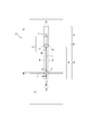
- FIG. 4 is a partially developed view schematically showing an enlarged part of a tread surface T of the tread 21 in a tire 20 according to another embodiment of the present invention. Specifically, one of the plurality of width direction grooves 23 formed in the tread surface T is enlarged and schematically shown.
- the tire 20 has the same tread pattern as the tire 10 according to the above-described embodiment shown in FIG. Therefore, about the same composition as the above-mentioned embodiment, the same numerals are attached and the explanation is omitted.
- the widthwise groove 23 is provided adjacent to and continuous with the tread ground contact end TE side of the second widthwise groove portion 3B, and includes a third widthwise groove portion 3C communicating with the tread ground contact end TE.
- the groove width W4 of the third widthwise groove portion 3C is larger than the groove width W3 of the second widthwise groove portion 3B. That is, the groove widths W3 and W4 of the second widthwise groove portion 3B and the third widthwise groove portion 3C satisfy the following relational expression (3). Groove width W4 of third width direction groove portion 3C> Groove width W3 of second width direction groove portion 3B (3)
- the groove width W4 of the third widthwise groove portion 3C is larger than the groove width W2 of the first widthwise groove portion 3A. That is, the groove widths W2 and W4 of the first width direction groove portion 3A and the third width direction groove portion 3C satisfy the following relational expression (4). Groove width W4 of third width direction groove portion 3C> Groove width W2 of first width direction groove portion 3A (4)
- the air passing through the width direction groove 3 is efficiently exhausted to the tire width direction outer side of the tread ground contact end TE, and the width direction from the circumferential direction groove 2 Since air is efficiently taken into the groove 3, air column resonance noise can be further reduced.
- the third widthwise groove portion 3C of the tire 20 is the groove width W2 of the first widthwise groove portion 3A in the area inward of the tire width direction, more specifically, in the tire widthwise direction than the tread ground contact end TE.
- the third widthwise groove portion 3C may have a groove width equivalent to the groove width W2 of the first widthwise groove portion 3A in a part of the third widthwise groove portion 3C.
- the groove width at the tread ground contact end TE position is larger than the groove width W2 of the first width direction groove portion 3A.
- FIG. 5 is a partially developed view schematically showing an enlarged part of the tread surface T of the tread 31 in a tire 30 according to still another embodiment of the present invention. Specifically, one of the plurality of width direction grooves 33 formed in the tread surface T is enlarged and schematically shown.
- the tire 30 has the same tread pattern as the tire 10 according to the above-described embodiment shown in FIG. Therefore, about the same composition as the above-mentioned embodiment, the same numerals are attached and the explanation is omitted.
- the third width direction groove portion 3C in the present embodiment has a groove width W4 of the third width direction groove portion 3C that extends over the entire length of the third width direction groove portion 3C. It is larger than the width W2.
- the air passing through the widthwise groove 3 is more efficiently exhausted to the outer side in the tire width direction of the tread ground contact end TE, and the intake of air from the circumferential groove 2 into the widthwise groove 3 is more efficient. Air column resonance can be further reduced.
- FIG. 6 is a partially developed view schematically showing an enlarged part of the tread surface T of the tread 41 in a tire 40 according to still another embodiment of the present invention. Specifically, one of the plurality of width direction grooves 43 formed in the tread surface T is enlarged and schematically shown.
- the tire 40 has the same tread pattern as the tire 10 according to the above-described embodiment shown in FIG. Therefore, about the same composition as the above-mentioned embodiment, the same numerals are attached and the explanation is omitted.
- the narrowing groove portion 3a formed in the first width direction groove portion 3A is provided adjacent to the second width direction groove portion 3B. ing.
- a narrowing groove portion 3 a formed in the first width direction groove portion 3 A is provided apart from the tire width direction inner end of the width direction groove 3.
- the narrowing groove 3a can be provided separately from both the second widthwise groove portion 3B and the tire widthwise inner end of the widthwise groove 3.
- the first width direction groove It can be provided at any position of the portion 3A.
- FIG. 7 is a partially developed view schematically showing a tread surface T of a tread 51 in a tire 50 according to still another embodiment of the present invention.
- the tire 50 according to the present embodiment extends in the tire circumferential direction at the shoulder land portion 4S (in the present embodiment, the tire circumferential direction at an angle of 0 ° with the tire circumferential direction, that is, along the tire circumferential direction). And further comprises at least one circumferential sipe 5.
- the block rigidity of the shoulder land portion 4S is appropriately reduced, so that pattern noise of the tire can be suppressed.
- the sipe width W5 of the circumferential sipe 5 By making the sipe width W5 of the circumferential sipe 5 smaller than the groove width W2 of the first width direction groove portion 3A, it is possible to suppress an excessive decrease in block rigidity of the shoulder land portion 4S. Further, by setting the sipe width W5 of the circumferential sipe 5 to be larger than the groove width W3 of the second width direction groove portion 3B, the rigidity of the shoulder land portion 4S is more appropriately reduced, and the tire pattern noise is reduced. It can reduce more reliably. In addition, the rigidity of the shoulder land portion 4S is appropriately reduced, so that the riding comfort when traveling the vehicle is improved.
- the circumferential sipe 5 intersects with the first widthwise groove portion 3A (the first widthwise groove portion 3A has an intersecting portion E intersecting with the circumferential sipe 5)
- the sipe width W5 of the circumferential sipe 5 smaller than the groove width W2 of the first widthwise groove portion 3A
- the air flowing through the first widthwise groove portion 3A is diverted to the circumferential sipe 5 Can be suppressed.
- air column resonance noise can be reduced more reliably.
- the crossing portion E means a region where the groove bottom of the first width direction groove portion 3A and the groove bottom of the circumferential sipe 5 overlap.
- FIG. 9 (a) is a cross-sectional view taken along the line III-III in FIG. 8, and FIG. 9 (b) is a modification thereof.
- the groove depth of the first width direction groove portion 3A (that is, the groove depth of the narrowed groove portion 3a) D1 and the groove depth D5 of the circumferential sipe 5 are the same.
- the groove bottom of the first widthwise groove portion 3A be raised by an arbitrary height HE of
- the circumferential sipe 5 may extend intermittently in the tire circumferential direction.
- the circumferential sipe 5 is disposed between the plurality of width direction grooves 3 provided in the shoulder land portion 4S such that both ends of the circumferential sipe 5 terminate in the shoulder land portion 4S.
- one end of the circumferential sipe 5 may be connected to the first widthwise groove portion 3A, or the first widthwise groove may be terminated such that both ends of the circumferential sipe 5 terminate in the shoulder land portion 4S. It can be arranged to cross the portion 3A.
- the shoulder land portion 4S further includes a width direction sipe 6 which extends in the tire width direction and does not communicate with the circumferential groove 2, and the width direction sipe 6 It does not intersect, and the width direction groove 3 and the width direction groove 3 alternately overlap in the tire circumferential direction at intervals with the width direction groove 3 and the second width direction groove portion 3B so as to overlap in the tire circumferential direction. It is preferable that it is arrange
- the rigidity of the land portion block is in the tire width direction region corresponding to the tire width direction extension region of the second width direction groove portion 3B.
- the widthwise sipe 6 is alternately spaced apart from the widthwise groove 3 in the tire circumferential direction with the widthwise groove 3 and the tire circumferential direction alternately, and overlaps the second widthwise groove portion 3B in the tire circumferential direction. If so arranged, the block rigidity in the tire width direction area corresponding to the tire extension area of the second width direction groove portion 3B is appropriately reduced, and the balance of the compression rigidity in each block partitioned by the width direction grooves 3 is achieved. Can be brought closer to uniformity.
- the widthwise sipe 6 in the depth direction of the sipe is formed in a zigzag shape in the tire circumferential direction. Specifically, it is preferable that at least a portion in the depth direction of the widthwise sipe 6 extend with two or more bending points. In this case, at the position of the widthwise sipe 6, it is possible to suppress an excessive decrease in the rigidity in each block divided by the widthwise groove 3. Furthermore, the widthwise sipe 6 has a normal direction extension region extending along the normal direction of the tread surface T on the tread surface T side of the width direction sipe 6, and the normal direction extension It is preferable to have a bend region that extends with normal to the region with two or more bend points.
- the tire 50 shown in FIGS. 7 to 9 has the same configuration as the tire 10 according to the embodiment shown in FIGS. 1 and 2 except that the circumferential sipe 5 and the widthwise sipe 6 are provided.
- the second widthwise groove portion 3B is formed by dividing the distance in the tire widthwise direction between the tire width direction inner end of the widthwise groove 3 and the tread contact edge TE into four equal parts.
- the tire width direction areas RA, RB, RC, and RD it is preferable that the tire width direction area RD on the outermost side in the tire width direction or the second tire width direction area RC from the tire width direction outside be provided.
- the second width direction groove portion 3B is provided in the region RC or the region RD” means that the entire second width direction groove portion 3B is included in the region RC or the region RD Point).
- the entire second widthwise groove portion 3B is provided in the region RC or the region RD, at least a portion of the second widthwise groove portion 3B is provided on the inner side in the tire width direction than the region RC.
- the air flow in the first width direction groove portion 3A closer to the circumferential direction groove 2 than the second width direction groove portion 3B can be secured more sufficiently, and the air flowing into the second width direction groove portion 3B Is faster, the damping effect due to viscosity is increased, and air column resonance noise can be further reduced.
- the second widthwise groove portion 3B be provided in the tire width direction area RC.
- “the second width direction groove portion 3B is provided in the region RC” indicates that the entire second width direction groove portion 3B is included (contained) in the region RC. .
- the second width direction groove portion 3B is almost always located in the tread contact surface during rolling of the tire, the air width resonance noise reduction effect by the second width direction groove portion 3B can be reduced. It is because it can be obtained more reliably.
- the intersection E of the first width direction groove portion 3A is the inner width end of the width direction groove 3 and the tread ground end TE. It is preferable to be provided on the inner side in the tire width direction than the middle point C.
- the arrangement position of the second width direction groove portion 3B described with reference to FIG. 10 is the same as in the other embodiments.
- concavo-convex processing is performed on at least a part of the surfaces of the both groove walls of the second width direction groove portion 3B, and the arithmetic average roughness Ra of the surface be 1.0 ⁇ m to 5.0 ⁇ m.
- the energy loss in the second widthwise groove portion 3B is increased, and the air column resonance noise can be further reduced.
- arithmetic mean roughness Ra is "arithmetic mean roughness Ra” prescribed
- the extension length of the second width direction groove portion 3B is preferably 1.0 mm or more and 3.0 mm or less. If it is 1.0 mm or more, the extension length of the first width direction groove portion 3A and / or the third width direction groove portion 3C becomes relatively short, so excessive reduction of the rigidity of the shoulder land portion 4S is suppressed. can do. Further, the attenuation effect of the sound wave in the second widthwise groove portion 3B is not particularly proportional to the extension length of the second widthwise groove portion 3B, and therefore, 3.0 mm or less is sufficient.
- the widthwise groove 3 including the first widthwise groove portion 3A having the narrowed groove portion 3a and the second widthwise groove portion 3B is in contact with the road surface of the tire (maximum load condition It is preferable to arrange two or more in the surface), and it is more preferable to arrange four or more.
- the attenuation effect of air column resonance sound by the second widthwise groove portion 3B is proportional to the number of the widthwise grooves 3 having the second widthwise groove portion 3B, but the rigidity of the shoulder land portion 4S is excessive. It is preferable to set it as six or less from a viewpoint which does not reduce to.
- the widthwise groove 3 including the first widthwise groove portion 3A having the narrowed groove portion 3a and the second widthwise groove portion 3B is one side of the tread surface T bordering on the tire equatorial plane TC. It may be provided only in one half (for example, the other half of the mounting outer side of the tire for which the mounting direction to the vehicle is specified).
- the shoulder land portion 4S may not include the third width direction groove portion 3C, and the second width direction groove portion 3B may be in direct communication with the tread ground end TE.
- no grooves or sipes are arranged in the center land portion 4C and the middle land portion 4M, but various grooves or sipes may optionally be provided according to the desired tire performance. it can.
- Inventive example tire 1-1 has a tread pattern shown in FIG. That is, the width direction groove 3 according to the present invention (that is, the first width direction groove portion communicating with the circumferential groove 2) according to the present invention, the shoulder land portion 4S extends in the tire width direction and communicates the circumferential groove 2 with the tread ground contact end TE.
- the widthwise groove 3 also has a third widthwise groove portion 3C.
- the comparative example tire 1-1 has the invention example tire 1-1 except that it has a conventional Helmholtz-type resonator instead of having the same width direction groove as the invention example tire 1 in the shoulder land portion. It is a similar tire.
- the comparative example tire 1-2 has a width direction groove in the shoulder land portion, and the invention does not include the first width direction groove portion and the second width direction groove portion having the narrowing groove portion.
- the tire is the same as the example tire 1-1.
- the comparative example tire 1-3 is a tire similar to the inventive example tire 1-1 except that it has a width direction groove in the shoulder land portion and the width direction groove does not have the second width direction groove portion. .
- the comparative example tire 1-4 is a tire similar to the inventive example tire 1-1 except that the first widthwise groove portion does not have the narrow groove portion.
- the comparative example tire 1-5 has a width direction groove in the shoulder land portion, and the width direction groove includes the first width direction groove portion and the second width direction groove portion.
- the tire of the invention example tire 1-1 is the same as that of the example tire 1-1 except that the groove width of the first width direction groove portion> the groove width of the second width direction groove portion.
- Inventive example tire 1-2 is the same tire as inventive example tire 1-1 except that it has the third width direction groove portion 3C shown in FIG.
- Inventive example tire 1-3 as shown in FIGS. 7 and 8, has shoulder land portion 4S having circumferential sipe 5 extending in the tire circumferential direction and intersecting first width direction groove portion 3A.
- the intersection E is not raised.
- Inventive example tire 1-4 as shown in FIGS. 7 and 8, has shoulder land portion 4S having circumferential sipe 5 extending in the tire circumferential direction and intersecting first width direction groove portion 3A.
- the tire is the same tire as Example tire 1-1 except that the groove width W2a of the width direction groove portion> the groove width W5 of the circumferential direction sipe 5> the groove width W3 of the second width direction groove portion ”.
- the intersection E is not raised.
- Example tire 2-1 basically has a tread pattern shown in FIG. 1, and the number of width direction grooves 3 according to the present invention in the contact surface of the tire is 1 for each shoulder land portion on both sides in the tire width direction. It is a book.
- the comparative example tire 2-1 is the same as the inventive example tire 2-1 except that the widthwise groove is not provided with the second widthwise groove portion.
- Invention tires 2-2 to 2-5 are inventions except that the number of width direction grooves 3 entering the contact surface of the tire is 2 to 5 for each of the shoulder land portions on both sides in the tire width direction.
- Example tire is similar to 2-1.
- test and evaluation method of the test tire is the same as the quietness test in [Test 1].
- the results are shown in Table 2 for the amount of reduction (dB) of air column resonance noise for the comparative example tire 2-1.
Landscapes
- Engineering & Computer Science (AREA)
- Mechanical Engineering (AREA)
- Tires In General (AREA)
Priority Applications (3)
| Application Number | Priority Date | Filing Date | Title |
|---|---|---|---|
| EP18837246.0A EP3659826B1 (de) | 2017-07-27 | 2018-06-26 | Reifen |
| US16/633,302 US20200148009A1 (en) | 2017-07-27 | 2018-06-26 | Tire |
| CN201880049098.6A CN110958950B (zh) | 2017-07-27 | 2018-06-26 | 轮胎 |
Applications Claiming Priority (2)
| Application Number | Priority Date | Filing Date | Title |
|---|---|---|---|
| JP2017-145856 | 2017-07-27 | ||
| JP2017145856A JP6887908B2 (ja) | 2017-07-27 | 2017-07-27 | タイヤ |
Publications (1)
| Publication Number | Publication Date |
|---|---|
| WO2019021723A1 true WO2019021723A1 (ja) | 2019-01-31 |
Family
ID=65040440
Family Applications (1)
| Application Number | Title | Priority Date | Filing Date |
|---|---|---|---|
| PCT/JP2018/024227 Ceased WO2019021723A1 (ja) | 2017-07-27 | 2018-06-26 | タイヤ |
Country Status (5)
| Country | Link |
|---|---|
| US (1) | US20200148009A1 (de) |
| EP (1) | EP3659826B1 (de) |
| JP (1) | JP6887908B2 (de) |
| CN (1) | CN110958950B (de) |
| WO (1) | WO2019021723A1 (de) |
Cited By (2)
| Publication number | Priority date | Publication date | Assignee | Title |
|---|---|---|---|---|
| WO2021111665A1 (ja) | 2019-12-05 | 2021-06-10 | 株式会社ブリヂストン | 空気入りタイヤ |
| US12090794B2 (en) | 2019-12-05 | 2024-09-17 | Bridgestone Corporation | Pneumatic tire |
Families Citing this family (5)
| Publication number | Priority date | Publication date | Assignee | Title |
|---|---|---|---|---|
| JP7091648B2 (ja) * | 2017-12-20 | 2022-06-28 | 住友ゴム工業株式会社 | タイヤ |
| JP7424814B2 (ja) * | 2019-12-13 | 2024-01-30 | 株式会社ブリヂストン | タイヤ |
| CN112976947B (zh) * | 2020-12-22 | 2024-05-14 | 风神轮胎股份有限公司 | 一种中长途低滚阻全轮位型轮胎胎面花纹 |
| JPWO2023105877A1 (de) * | 2021-12-10 | 2023-06-15 | ||
| CN114161886A (zh) * | 2021-12-17 | 2022-03-11 | 风神轮胎股份有限公司 | 一种适用于牵引车导向轮位的轮胎 |
Citations (7)
| Publication number | Priority date | Publication date | Assignee | Title |
|---|---|---|---|---|
| JPH0569706A (ja) * | 1991-09-10 | 1993-03-23 | Ohtsu Tire & Rubber Co Ltd :The | 空気入りタイヤ |
| JP2011051529A (ja) | 2009-09-03 | 2011-03-17 | Bridgestone Corp | タイヤ |
| JP2011143898A (ja) * | 2010-01-18 | 2011-07-28 | Bridgestone Corp | 空気入りタイヤ |
| JP2013107501A (ja) * | 2011-11-21 | 2013-06-06 | Toyo Tire & Rubber Co Ltd | 空気入りタイヤ |
| JP2013539735A (ja) * | 2010-10-14 | 2013-10-28 | コンパニー ゼネラール デ エタブリッスマン ミシュラン | タイヤ用ノイズ減衰装置 |
| JP2014166827A (ja) | 2013-02-28 | 2014-09-11 | Bridgestone Corp | 空気入りタイヤ |
| JP2015214303A (ja) * | 2014-05-13 | 2015-12-03 | 株式会社ブリヂストン | タイヤ |
Family Cites Families (10)
| Publication number | Priority date | Publication date | Assignee | Title |
|---|---|---|---|---|
| JP3238101B2 (ja) * | 1997-06-27 | 2001-12-10 | 住友ゴム工業株式会社 | 重荷重用空気入りタイヤ |
| JP4299804B2 (ja) * | 2005-04-18 | 2009-07-22 | 住友ゴム工業株式会社 | 空気入りタイヤ |
| WO2007114430A1 (ja) * | 2006-03-31 | 2007-10-11 | Bridgestone Corporation | 空気入りタイヤ |
| JP5798106B2 (ja) * | 2010-02-22 | 2015-10-21 | 株式会社ブリヂストン | タイヤ |
| DE102010016977B4 (de) * | 2010-05-18 | 2023-08-17 | Continental Reifen Deutschland Gmbh | Fahrzeugluftreifen |
| RU2599856C1 (ru) * | 2013-03-06 | 2016-10-20 | Дзе Йокогама Раббер Ко., Лтд. | Пневматическая шина |
| JP6306436B2 (ja) * | 2014-05-30 | 2018-04-04 | 株式会社ブリヂストン | 空気入りタイヤ |
| CN203937444U (zh) * | 2014-06-12 | 2014-11-12 | 重庆红旗杰勋车轮有限公司 | 轮胎 |
| JP2017024542A (ja) * | 2015-07-22 | 2017-02-02 | 横浜ゴム株式会社 | 空気入りタイヤ |
| FR3042738B1 (fr) * | 2015-10-27 | 2017-11-24 | Michelin & Cie | Pneumatique a couches de travail comprenant des monofilaments et a bande de roulement rainuree |
-
2017
- 2017-07-27 JP JP2017145856A patent/JP6887908B2/ja not_active Expired - Fee Related
-
2018
- 2018-06-26 US US16/633,302 patent/US20200148009A1/en not_active Abandoned
- 2018-06-26 CN CN201880049098.6A patent/CN110958950B/zh not_active Expired - Fee Related
- 2018-06-26 EP EP18837246.0A patent/EP3659826B1/de active Active
- 2018-06-26 WO PCT/JP2018/024227 patent/WO2019021723A1/ja not_active Ceased
Patent Citations (7)
| Publication number | Priority date | Publication date | Assignee | Title |
|---|---|---|---|---|
| JPH0569706A (ja) * | 1991-09-10 | 1993-03-23 | Ohtsu Tire & Rubber Co Ltd :The | 空気入りタイヤ |
| JP2011051529A (ja) | 2009-09-03 | 2011-03-17 | Bridgestone Corp | タイヤ |
| JP2011143898A (ja) * | 2010-01-18 | 2011-07-28 | Bridgestone Corp | 空気入りタイヤ |
| JP2013539735A (ja) * | 2010-10-14 | 2013-10-28 | コンパニー ゼネラール デ エタブリッスマン ミシュラン | タイヤ用ノイズ減衰装置 |
| JP2013107501A (ja) * | 2011-11-21 | 2013-06-06 | Toyo Tire & Rubber Co Ltd | 空気入りタイヤ |
| JP2014166827A (ja) | 2013-02-28 | 2014-09-11 | Bridgestone Corp | 空気入りタイヤ |
| JP2015214303A (ja) * | 2014-05-13 | 2015-12-03 | 株式会社ブリヂストン | タイヤ |
Non-Patent Citations (1)
| Title |
|---|
| See also references of EP3659826A4 |
Cited By (3)
| Publication number | Priority date | Publication date | Assignee | Title |
|---|---|---|---|---|
| WO2021111665A1 (ja) | 2019-12-05 | 2021-06-10 | 株式会社ブリヂストン | 空気入りタイヤ |
| US12090794B2 (en) | 2019-12-05 | 2024-09-17 | Bridgestone Corporation | Pneumatic tire |
| US12122190B2 (en) | 2019-12-05 | 2024-10-22 | Bridgestone Corporation | Pneumatic tire |
Also Published As
| Publication number | Publication date |
|---|---|
| EP3659826A4 (de) | 2021-04-07 |
| US20200148009A1 (en) | 2020-05-14 |
| JP6887908B2 (ja) | 2021-06-16 |
| EP3659826B1 (de) | 2022-06-01 |
| JP2019026018A (ja) | 2019-02-21 |
| CN110958950A (zh) | 2020-04-03 |
| CN110958950B (zh) | 2022-04-12 |
| EP3659826A1 (de) | 2020-06-03 |
Similar Documents
| Publication | Publication Date | Title |
|---|---|---|
| WO2019021723A1 (ja) | タイヤ | |
| US9302553B2 (en) | Pneumatic tire | |
| JP5266307B2 (ja) | 空気入りタイヤ | |
| JP6762267B2 (ja) | タイヤ | |
| EP2796298B1 (de) | Luftreifen | |
| JP6450224B2 (ja) | 空気入りタイヤ | |
| US10889150B2 (en) | Pneumatic tire | |
| JPWO2005068225A1 (ja) | 空気入りタイヤ | |
| US10086656B2 (en) | Heavy-duty tire | |
| JP5613273B2 (ja) | 空気入りタイヤ | |
| JP6657707B2 (ja) | 空気入りタイヤ | |
| JP6851858B2 (ja) | タイヤ | |
| JP6421652B2 (ja) | 空気入りタイヤ | |
| JP7583258B2 (ja) | タイヤ | |
| EP3461657A1 (de) | Reifen | |
| JP6851859B2 (ja) | タイヤ | |
| JP6571993B2 (ja) | 空気入りタイヤ | |
| JP7108632B2 (ja) | 空気入りタイヤ | |
| JP7633490B2 (ja) | タイヤ | |
| JP7633491B2 (ja) | タイヤ | |
| JP7074586B2 (ja) | 空気入りタイヤ | |
| JP2011168220A (ja) | 空気入りタイヤ | |
| JP2024099172A (ja) | 空気入りタイヤ | |
| JP2024120241A (ja) | 重荷重タイヤ | |
| JP2024099174A (ja) | 空気入りタイヤ |
Legal Events
| Date | Code | Title | Description |
|---|---|---|---|
| 121 | Ep: the epo has been informed by wipo that ep was designated in this application |
Ref document number: 18837246 Country of ref document: EP Kind code of ref document: A1 |
|
| NENP | Non-entry into the national phase |
Ref country code: DE |
|
| WWE | Wipo information: entry into national phase |
Ref document number: 2018837246 Country of ref document: EP |
|
| ENP | Entry into the national phase |
Ref document number: 2018837246 Country of ref document: EP Effective date: 20200227 |