WO2019021730A1 - Pneumatique - Google Patents
Pneumatique Download PDFInfo
- Publication number
- WO2019021730A1 WO2019021730A1 PCT/JP2018/024441 JP2018024441W WO2019021730A1 WO 2019021730 A1 WO2019021730 A1 WO 2019021730A1 JP 2018024441 W JP2018024441 W JP 2018024441W WO 2019021730 A1 WO2019021730 A1 WO 2019021730A1
- Authority
- WO
- WIPO (PCT)
- Prior art keywords
- noise suppressing
- tire
- suppressing body
- noise
- communication device
- Prior art date
- Legal status (The legal status is an assumption and is not a legal conclusion. Google has not performed a legal analysis and makes no representation as to the accuracy of the status listed.)
- Ceased
Links
Images




Classifications
-
- B—PERFORMING OPERATIONS; TRANSPORTING
- B60—VEHICLES IN GENERAL
- B60C—VEHICLE TYRES; TYRE INFLATION; TYRE CHANGING; CONNECTING VALVES TO INFLATABLE ELASTIC BODIES IN GENERAL; DEVICES OR ARRANGEMENTS RELATED TO TYRES
- B60C19/00—Tyre parts or constructions not otherwise provided for
- B60C19/002—Noise damping elements provided in the tyre structure or attached thereto, e.g. in the tyre interior
-
- B—PERFORMING OPERATIONS; TRANSPORTING
- B60—VEHICLES IN GENERAL
- B60C—VEHICLE TYRES; TYRE INFLATION; TYRE CHANGING; CONNECTING VALVES TO INFLATABLE ELASTIC BODIES IN GENERAL; DEVICES OR ARRANGEMENTS RELATED TO TYRES
- B60C19/00—Tyre parts or constructions not otherwise provided for
-
- B—PERFORMING OPERATIONS; TRANSPORTING
- B60—VEHICLES IN GENERAL
- B60C—VEHICLE TYRES; TYRE INFLATION; TYRE CHANGING; CONNECTING VALVES TO INFLATABLE ELASTIC BODIES IN GENERAL; DEVICES OR ARRANGEMENTS RELATED TO TYRES
- B60C23/00—Devices for measuring, signalling, controlling, or distributing tyre pressure or temperature, specially adapted for mounting on vehicles; Arrangement of tyre inflating devices on vehicles, e.g. of pumps or of tanks; Tyre cooling arrangements
-
- B—PERFORMING OPERATIONS; TRANSPORTING
- B60—VEHICLES IN GENERAL
- B60C—VEHICLE TYRES; TYRE INFLATION; TYRE CHANGING; CONNECTING VALVES TO INFLATABLE ELASTIC BODIES IN GENERAL; DEVICES OR ARRANGEMENTS RELATED TO TYRES
- B60C23/00—Devices for measuring, signalling, controlling, or distributing tyre pressure or temperature, specially adapted for mounting on vehicles; Arrangement of tyre inflating devices on vehicles, e.g. of pumps or of tanks; Tyre cooling arrangements
- B60C23/02—Signalling devices actuated by tyre pressure
- B60C23/04—Signalling devices actuated by tyre pressure mounted on the wheel or tyre
- B60C23/0491—Constructional details of means for attaching the control device
- B60C23/0493—Constructional details of means for attaching the control device for attachment on the tyre
-
- G—PHYSICS
- G06—COMPUTING OR CALCULATING; COUNTING
- G06K—GRAPHICAL DATA READING; PRESENTATION OF DATA; RECORD CARRIERS; HANDLING RECORD CARRIERS
- G06K19/00—Record carriers for use with machines and with at least a part designed to carry digital markings
- G06K19/06—Record carriers for use with machines and with at least a part designed to carry digital markings characterised by the kind of the digital marking, e.g. shape, nature, code
- G06K19/067—Record carriers with conductive marks, printed circuits or semiconductor circuit elements, e.g. credit or identity cards also with resonating or responding marks without active components
- G06K19/07—Record carriers with conductive marks, printed circuits or semiconductor circuit elements, e.g. credit or identity cards also with resonating or responding marks without active components with integrated circuit chips
- G06K19/077—Constructional details, e.g. mounting of circuits in the carrier
- G06K19/0772—Physical layout of the record carrier
- G06K19/07728—Physical layout of the record carrier the record carrier comprising means for protection against impact or bending, e.g. protective shells or stress-absorbing layers around the integrated circuit
-
- G—PHYSICS
- G06—COMPUTING OR CALCULATING; COUNTING
- G06K—GRAPHICAL DATA READING; PRESENTATION OF DATA; RECORD CARRIERS; HANDLING RECORD CARRIERS
- G06K19/00—Record carriers for use with machines and with at least a part designed to carry digital markings
- G06K19/06—Record carriers for use with machines and with at least a part designed to carry digital markings characterised by the kind of the digital marking, e.g. shape, nature, code
- G06K19/067—Record carriers with conductive marks, printed circuits or semiconductor circuit elements, e.g. credit or identity cards also with resonating or responding marks without active components
- G06K19/07—Record carriers with conductive marks, printed circuits or semiconductor circuit elements, e.g. credit or identity cards also with resonating or responding marks without active components with integrated circuit chips
- G06K19/077—Constructional details, e.g. mounting of circuits in the carrier
- G06K19/07749—Constructional details, e.g. mounting of circuits in the carrier the record carrier being capable of non-contact communication, e.g. constructional details of the antenna of a non-contact smart card
- G06K19/07758—Constructional details, e.g. mounting of circuits in the carrier the record carrier being capable of non-contact communication, e.g. constructional details of the antenna of a non-contact smart card arrangements for adhering the record carrier to further objects or living beings, functioning as an identification tag
- G06K19/07764—Constructional details, e.g. mounting of circuits in the carrier the record carrier being capable of non-contact communication, e.g. constructional details of the antenna of a non-contact smart card arrangements for adhering the record carrier to further objects or living beings, functioning as an identification tag the adhering arrangement making the record carrier attachable to a tyre
-
- B—PERFORMING OPERATIONS; TRANSPORTING
- B60—VEHICLES IN GENERAL
- B60C—VEHICLE TYRES; TYRE INFLATION; TYRE CHANGING; CONNECTING VALVES TO INFLATABLE ELASTIC BODIES IN GENERAL; DEVICES OR ARRANGEMENTS RELATED TO TYRES
- B60C19/00—Tyre parts or constructions not otherwise provided for
- B60C2019/004—Tyre sensors other than for detecting tyre pressure
Definitions
- the present invention relates to a pneumatic tire.
- a communication device such as a sensor for detecting an internal state of a tire such as air pressure of a tire, an RF tag provided with a storage unit capable of storing unique identification information of a tire, etc.
- An embedded configuration is known.
- the sensor as the communication device can determine the state of the running tire, and can utilize various tire information acquired from the storage unit of the RF tag as the communication device for maintenance service and the like.
- Patent Document 1 discloses a configuration in which a wireless tag is attached to a sponge material fixed to the inner surface of a tire. Further, in Patent Document 2, a strip-like sheet fixed to the inner surface of a tire is formed of a first layer made of a first sponge material excellent in sound absorption performance and a second layer made of a second sponge material excellent in anti-reflection performance of sound. It is disclosed to form as a multilayer structure of and.
- the cavity resonance energy is converted to another energy to absorb the sound by disposing the sponge material in the tire lumen defined by the pneumatic tire and the rim. , Can reduce the cavity resonance sound.
- the wireless tag as a communication device is attached to a sponge material to protect the wireless tag from impact, vibration, and the like.
- the wireless tag may be dropped from the sponge material into the tire lumen due to impact, vibration or the like during traveling. Therefore, it is preferable to improve the position fixability of the wireless tag by the sponge material.
- the sponge material is formed of a soft material to protect the wireless tag from impact, vibration, etc.
- the sponge material is easily deformed by impact during traveling, vibration, air flow in the tire lumen, or the like.
- breakage is likely to occur in which small pieces of the sponge material separate from the surface of the sponge material, and the separated small pieces of the sponge material may be scattered in the tire lumen.
- the present invention has a configuration capable of realizing both the improvement of the position fixing property of the communication device by the sponge material and the improvement of the durability of the sponge material, in addition to the protection of the communication device by the sponge material,
- the purpose is to provide a tire.
- a pneumatic tire as one aspect of the present invention is a sponge material fixed to the inner surface of the tire, the first noise suppressing body comprising a sponge material, and the sponge material being disposed on the tire inner space side of the first noise suppressing body And a communication device held between the first and the second noise suppressors, wherein the second noise suppressor is the first noise suppressor. Harder than the body.
- the air having a configuration capable of achieving both the improvement of the position fixability of the communication device by the sponge material and the improvement of the durability of the sponge material.
- a tire can be provided.
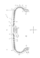
- FIG. 2 is a cross-sectional view in the tire width direction of the single pneumatic tire shown in FIG. It is an expanded sectional view which expands and shows the tread part of the pneumatic tire shown in FIG.
- RF tag as an example of a communication apparatus, and the reader / writer which can be wirelessly communicated with this RF tag.
- FIGS. 1 to 10 An embodiment of a pneumatic tire according to the present invention will be exemplarily described with reference to FIGS. 1 to 10.
- symbol is attached
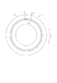
- FIG. 1 is a view showing an assembly 100 including a pneumatic tire 1 (hereinafter simply referred to as “tire 1”) and a rim 2.
- FIG. 1 is a cross-sectional view showing a cross section parallel to the tire width direction A including the tire rotation axis of the assembly 100 (hereinafter, referred to as “tire width direction cross-sectional view”).
- FIG. 2 is a cross-sectional view in the tire width direction showing the single tire 1 shown in FIG.
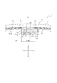
- FIG. 3 is an enlarged cross-sectional view showing a tread portion 1a which is a part of the tire 1 shown in FIG. In other words, the tire 1 shown in FIG. 2 and FIG. 3 shows a state where it is not mounted on the rim 2.
- the tire 1 is attached to the rim 2.
- the assembly 100 has an annular surface formed by the inner surface of the tire 1 (hereinafter, referred to as “tire inner surface”) and the outer surface of the rim 2 (hereinafter, referred to as “rim outer surface”).
- the tire lumen 101 is divided.
- segmented only by tire inner surface in a tire width direction cross sectional view is hereafter described as "in-tire space 102.”
- the rim 2 includes a rim main body 2a on which a bead portion 1c of the tire 1 described later is mounted, and a disc 2b that holds the rim main body 2a and is attached to an axle.
- the rim 2 of the present embodiment is a metal two-piece wheel rim, but is not limited to this, and may be a one-piece rim or the like. Further, the rim body 2a protrudes to the outside in the tire radial direction B from both ends of the rim seat portion 2a1 on which bead members 4 of the tire 1 described later are attached to the outside in the tire radial direction B And a rim flange portion 2a2.
- the tire 1 includes a tread portion 1a, a pair of sidewall portions 1b extending inward in a tire radial direction B from both end portions of the tread portion 1a in the tire width direction A, and an inner side of each sidewall portion 1b in the tire radial direction B. And a pair of bead portions 1c provided at the end of the The tire 1 of the present embodiment is a tubeless type radial tire for passenger cars.
- tread portion 1a refers to two planes P1 parallel to the tire radial direction B passing through the belt ends Q (see FIG. 2) positioned on the outermost sides of the belt 6 in the tire width direction A described later.
- the part (except bead part 1c) pinched by P2 is meant.
- the bead part 1c means the part in which the bead member 4 mentioned later in tire radial direction B is located.
- sidewall part 1b means a portion between tread part 1a and bead part 1c.
- the tire inner surface defining the tire inner cavity 101 is described as the inner surface 31 of the tread portion 1a (hereinafter referred to as “tread inner surface 31”) and the inner surface 32 of the sidewall portion 1b (hereinafter referred to as “sidewall inner surface 32" And an inner surface 33 of the bead portion 1c (hereinafter referred to as “bead inner surface 33").
- the tire 1 includes a noise suppressing body 3, a bead member 4, a carcass 5, a belt 6, a tread rubber 7, side rubbers 8, an inner liner 9, and a communication device 10.
- the noise suppressing body 3 includes a first noise suppressing body 3 a and a second noise suppressing body 3 b.
- the first noise suppressing body 3a is made of a sponge material. Further, the first noise suppressing body 3a is fixed to the inner surface of the tire.
- the second noise suppressing body 3b is made of a sponge material. Further, the second noise suppressing body 3b is disposed on the in-tire space 102 side (the same as the tire inner cavity 101 side in the assembly 100 of FIG. 1) of the first noise suppressing body 3a.
- the tire inner space side of the first noise control body means the side where the tire inner space is located with respect to the first noise control body, and the tire inner surface of the first noise control body. It does not mean only the side opposite to the fixing surface fixed to the. That is, in the present embodiment, the in-tire space 102 side of the first noise control body 3a is the inner side in the tire radial direction B of the first noise control body 3a in the tire width direction sectional view shown in FIG. The lower side) and both sides (the left and right sides in FIG. 3) of the first noise reduction body 3a in the tire width direction A are meant.
- the second noise suppressing body 3b of the present embodiment is disposed on the inner side in the tire radial direction B of the first noise suppressing body 3a as the in-tire space 102 side of the first noise suppressing body 3a.
- the second noise suppressing member may be disposed on one side or both sides in the tire width direction A of the first noise suppressing member 3 a as the tire inner space 102 side of the first noise suppressing member 3 a.
- the second noise suppressing body 3 b is harder than the first noise suppressing body 3 a.
- the term "hardness” as used herein refers to the value measured according to method A in section 6.4 among the methods for measuring "hardness test” in section 6 of JIS K 6400-2 (2012). .
- the communication device 10 is held between the first noise suppressing body 3 a and the second noise suppressing body 3 b. Therefore, by forming the first noise suppressing body 3a with a soft sponge material, the first noise suppressing body 3a absorbs an impact or vibration from the tire inner surface side of the tire 1, and the communication device 10 receives an impact or vibration. Transmission can be suppressed.
- the second noise suppressing body 3b is formed of a hard sponge material, so that the second noise suppressing body 3b is prevented from being deformed by an impact during traveling on a road surface, vibration, air flow in the tire lumen, and the like. can do.
- the second noise suppressing body 3b a sponge material harder than the first noise suppressing body 3a is used as the second noise suppressing body 3b, a sponge material the same as or softer than the first noise suppressing body 3a is used as the second noise suppressing body.
- the durability of the second noise suppressing body 3b can be improved.
- the communication device 10 is held between the first noise suppressing member 3 a and the second noise suppressing member 3 b, the second noise suppressing member 3 b is a cover, and the communication device 10 is on the in-tire space 102 side. It is hard to drop out. Thereby, the position fixability of the communication device 10 can be improved.
- the hardness of the first noise damper 3a and the second noise damper 3b is set to the above-described hardness relationship, and the communication device 10 is provided between the first noise damper 3a and the second noise damper 3b.
- the protection of the communication device 10 by the sponge material by maintaining the configuration, it is possible to realize both the improvement of the position fixing property of the communication device 10 by the sponge material and the improvement of the durability of the sponge material. it can.
- the hardnesses of the first noise suppressing member 3a and the second noise suppressing member 3b made of a sponge material be set in the range of 25N to 55N so as to have the above-described hardness relationship.
- the first noise suppressing member 3a be set in the range of 30N to 50N.
- the second noise suppressing member 3b is set from the range of 35N to 45N.
- the sponge material constituting the first noise suppressing body 3a and the second noise suppressing body 3b is a sponge-like porous structure, and includes, for example, a so-called sponge having open cells in which rubber or synthetic resin is foamed.
- the sponge material includes web-like materials in which animal fibers, plant fibers or synthetic fibers are entangled and integrally connected.
- the above-mentioned "porous structure" is the meaning including not only the structure which has an open cell but the structure which has a closed cell. However, from the viewpoint of sound absorption performance, it is preferable to use a structure having open cells.
- the sponge material as described above absorbs sound by converting the vibrational energy of the air in which the air gap formed on the surface and the inside vibrates into thermal energy. This reduces cavity resonance in the tire lumen.
- the material of the sponge material examples include synthetic polyurethane resin sponges such as ether polyurethane foam, ester polyurethane foam, polyethylene sponge, chloroprene rubber sponge (CR sponge), ethylene propylene rubber sponge (EPDM sponge), nitrile rubber sponge (NBR sponge) And rubber sponges. It is preferable to use a polyurethane-based or polyethylene-based sponge including an ether-based polyurethane sponge, in view of noise suppression properties, lightness, foam adjustability, durability, and the like.
- synthetic polyurethane resin sponges such as ether polyurethane foam, ester polyurethane foam, polyethylene sponge, chloroprene rubber sponge (CR sponge), ethylene propylene rubber sponge (EPDM sponge), nitrile rubber sponge (NBR sponge) And rubber sponges. It is preferable to use a polyurethane-based or polyethylene-based sponge including an ether-based polyurethane sponge, in view of noise suppression properties, lightness, foam adjustability, durability, and the like.
- the specific gravity of the sponge material is preferably in the range of 0.005 to 0.06, preferably 0.01 to 0.04, in consideration of the balance between the increase in tire weight and the effect of reducing cavity resonance noise. It is more preferable to set it to 0.01 to 0.03.
- the volume of the noise suppressing body 3 which is the sum of the volumes of the first noise suppressing body 3 a and the second noise suppressing body 3 b be 0.4% to 20% of the total volume of the tire inner cavity 101. .
- the volume of the noise suppressing body 3 is more preferably 1% or more, more preferably 2% or more, and particularly preferably 4% or more of the entire volume of the tire lumen 101.
- the volume of the noise suppressing body 3 is more preferably 16% or less of the entire volume of the tire lumen 101, and particularly preferably 10% or less.
- first noise suppressing body 3a and the second noise suppressing body 3b will be described later.
- the bead member 4 is embedded in the bead portion 1c.
- the bead member 4 includes a bead core 4a and a rubber bead filler 4b located on the outer side of the bead core 4a in the tire radial direction B.
- the bead core 4a is provided with a plurality of bead wires whose circumference is covered with rubber.
- the bead wire is formed of a steel cord.
- the steel cord can be made of, for example, a monofilament of steel or a stranded wire. In addition, you may use an organic fiber, a carbon fiber, etc. as a bead wire.
- the carcass 5 straddles between the pair of bead portions 1c, more specifically, between the bead cores 4a of the pair of bead members 4, and extends in a toroidal shape.
- the carcass 5 has at least a radial structure.
- the carcass 5 is composed of one or more (one in the present embodiment) carcass plies 5a in which carcass cords are arranged at an angle of 75 ° to 90 ° with respect to the tire circumferential direction C (see FIG. 7).
- the carcass ply 5a includes a ply body located between a pair of bead cores 4a, and a ply turnback which is folded from the inside to the outside in the tire width direction A around the bead cores 4a at both ends of the ply body. ing.
- the bead filler 4b which extends in a tapered shape from the bead core 4a to the outer side in the tire radial direction B is disposed.
- a polyester cord is employed as the carcass cord constituting the carcass ply 5a, but in addition to this, an organic fiber cord such as nylon, rayon or aramid, or a steel cord may be employed if necessary.
- the number of carcass plies 5a may be two or more.
- the belt 6 includes one or more (five in the present embodiment) belt layers disposed on the outer side in the tire radial direction B with respect to the crown portion of the carcass 5. Specifically, as shown in FIG. 3, the belt 6 of the present embodiment includes an inclined belt 6 a and a circumferential belt 6 b.
- the inclined belt 6 a includes one or more (two in this embodiment) inclined belt layers disposed on the outer side in the tire radial direction B with respect to the crown portion of the carcass 5.
- the inclined belt 6a of the present embodiment includes a first inclined belt layer 6a1 and a second inclined belt layer 6a2 stacked in the tire radial direction B.
- Each of the first inclined belt layer 6a1 and the second inclined belt layer 6a2 is a belt ply in which steel cords as metal belt cords are arranged at an angle of 10 ° to 40 ° with respect to the tire circumferential direction C (see FIG. 7). It is formed of The two belt plies are laid one on another with the direction of inclination of the belt cords different from one another.
- the belt cords cross each other between the belt plies, the belt rigidity is enhanced, and the substantially full width of the tread portion 1a can be reinforced by the tag effect.
- the second inclined belt layer 6a2 located outside in the tire radial direction B is formed narrower than the first inclined belt layer 6a1 located inside in the tire radial direction B. Therefore, in the present embodiment, the first inclined belt layer 6a1 located on the inner side in the tire radial direction B extends to the outer side in the tire width direction A more than the second inclined belt layer 6a2 located on the outer side in the tire radial direction B. It exists.
- the first inclined belt layer positioned inside the tire radial direction B may be formed narrower than the second inclined belt layer positioned outside the tire radial direction B. That is, the second inclined belt layer located outside in the tire radial direction B may extend to the outside in the tire width direction A more than the first inclined belt layer located inside in the tire radial direction B.
- the inclined belt 6a may be configured by a belt layer of only one layer, or may be configured by a belt layer of three or more layers.
- the circumferential belt 6b is provided with one or more (three in this embodiment) circumferential belt layers arranged on the outer side in the tire radial direction B with respect to the inclined belt 6a.
- the circumferential belt 6b includes a first circumferential belt layer 6b1, a second circumferential belt layer 6b2 and a third circumferential belt layer 6b3 stacked in the tire radial direction B.
- Each of the first circumferential belt layer 6b1, the second circumferential belt layer 6b2 and the third circumferential belt layer 6b3 has a nylon cord as a belt cord of organic fiber at 10 ° to the tire circumferential direction C (see FIG. 7)
- it is formed of a belt ply spirally wound around the tire rotation axis at an angle of preferably 5 ° or less.
- the circumferential belt 6b of the present embodiment is constituted by three circumferential belt layers arranged on the outer side in the tire radial direction B with respect to the inclined belt 6a.
- the present invention is not limited to this configuration.
- it may be a circumferential belt composed of four or more circumferential belt layers.
- the length relationship between the circumferential belt layers in the tire width direction A, the length relationship between each circumferential belt layer and each inclined belt layer in the tire width direction A, and the positional relationship between belt edges in the circumferential belt layers The positional relationship of the belt end between each circumferential belt layer and each inclined belt layer, etc. can be appropriately designed according to the desired performance without being limited to the configuration of the present embodiment, and the belt structure of the present embodiment It is not limited to
- the tread rubber 7 constitutes a surface on the outer side in the tire radial direction B of the tread portion 1a (hereinafter referred to as "tread outer surface"), and on the tread outer surface in the tire circumferential direction C (see FIG. 7).
- a tread pattern including an extending circumferential groove 7a and a not-shown width direction groove extending in the tire width direction A is formed.
- the side rubber 8 constitutes the outer surface of the sidewall portion 1 b in the tire width direction A, and is integrally formed with the above-described tread rubber 7.
- the inner liner 9 is laminated on the inner surface of the carcass 5 and is made of butyl-based rubber having low air permeability.
- butyl type rubber means butyl rubber and halogenated butyl rubber which is its derivative.
- the first noise suppressing body 3a is fixed to the inner liner 9 by a double-sided adhesive tape, an adhesive or the like. Therefore, in the region of the inner liner 9 to which the first noise suppressing body 3a is fixed, low butyl content in which the compounding amount of the butyl-based rubber is lower than the region to which the first noise suppressing body 3a is not fixed It may be a blending area.
- FIG. 4 is a view showing an RF tag as an example of the communication device 10 and a reader / writer 60 capable of wirelessly communicating with the RF tag.
- the RF tag includes a storage unit 10 a that stores identification information of the tire 1, an antenna unit 10 b that can transmit to and receive from the reader / writer 60 located outside the tire 1, and information to the storage unit 10 a. And a control unit 10c capable of reading information from the storage unit 10a.
- the RF tag as the communication device 10 can receive, from the antenna unit 60a of the reader / writer 60, information transmitted on a radio wave or a magnetic field by the antenna unit 10b.
- Electric power is generated in the antenna unit 10b of the RF tag by rectification (in the case of a radio wave) or resonance (in the case of a magnetic field), and the storage unit 10a and the control unit 10c perform predetermined operations.
- the control unit 10 c reads the information in the storage unit 10 a of the RF tag, puts it on a radio wave or a magnetic field, and sends back (sends) the reader / writer 60 from the antenna unit 10 b.
- the antenna unit 60a of the reader / writer 60 receives a radio wave or a magnetic field from the RF tag.
- the control unit 60b of the reader / writer 60 can acquire the information stored in the storage unit 10a of the RF tag by extracting the received information.
- the storage unit 10a and the control unit 10c described above can be configured by, for example, an integrated circuit (IC chip) including a non-volatile memory.
- the storage unit 10a of the RF tag as the communication device 10 stores, for example, unique identification information of the tire 1 that can specify each tire for each tire, such as a manufacturer of the tire 1, a manufacturing factory, and a manufacturing date. There is.
- the storage unit 10a may store tire history information such as the distance traveled by the tire, the number of times of rapid braking, the number of times of rapid dispatching, and the number of times of sudden turning as rewritable information by the reader / writer 60.
- a sensor that detects a tire internal temperature, a tire internal pressure, a tire acceleration and the like may be provided in the tire bore 101, and the storage unit 10a may store detection information detected by these sensors.
- the RF tag as the communication device 10 can acquire detection information of the sensor by performing wireless communication with the sensor through the antenna unit 10 b.
- the communication device 10 may be configured to wirelessly communicate with a predetermined device outside the tire 1, and is not limited to the above-described RF tag.
- a predetermined device outside the tire 1 For example, an acceleration sensor that detects the acceleration of the tire 1
- the communication device 10 may be an internal pressure sensor that detects the internal pressure of the tire 1 or the like.
- the communication device 10 is not a sensor such as an acceleration sensor, for example, and an RF tag that is not related to the above-mentioned distance element, as the distance element such as tire displacement amount per unit time fluctuates measurement accuracy. Is preferred.
- the RF tag may be distorted due to deformation, impact, vibration or the like of the tire 1 and may be damaged. Therefore, in the case of the RF tag, it is preferable to make the first noise-damping body 3a absorb the impact, vibration and the like from the tire inner surface side of the tire 1 to make it difficult to transmit the impact and vibration to the RF tag.
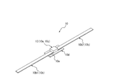
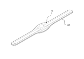
- FIG. 5 and 6 are perspective views showing an RF tag as the communication device 10 according to the present embodiment.
- the RF tag as the communication apparatus 10 of the present embodiment receives the first antenna 10b1 and the second antenna 10b2 constituting the antenna unit 10b, and the first antenna 10b1 and the second antenna 10b2.
- the IC chip 13 constituting the control unit 10c and the storage unit 10a, which operates by the dielectric electromotive force generated by radio waves, the plate-like support member 10d to which the IC chip 13 is attached, the IC chip 13, and the first And a conductive conduction member 10e electrically connecting the antenna 10b1 and the second antenna 10b2 to each other.
- FIG. 6 is a perspective view showing a state in which the RF tag as the communication device 10 shown in FIG. 5 is covered by the covering portion 10 f.
- the covering portion 10 f is formed of rubber or resin.
- the RF tag as the communication device 10 in a state where the periphery is covered by the covering portion 10 f is held between the first noise suppressing member 3 a and the second noise suppressing member 3 b. It is done.
- the specific configuration of the RF tag as the communication device 10 is not particularly limited as long as it is held between the first noise suppressing body 3a and the second noise suppressing body 3b. . Therefore, the communication device 10 may be configured to be held by being held between the first noise suppressing member 3a and the second noise suppressing member 3b by the first noise suppressing member 3a and the second noise suppressing member 3b. .
- Such a configuration is, for example, a direction along the inner surface of the tire (see FIG. 3 in the tire width direction A) in the tire width direction sectional view (see FIG. 3 etc.) of the first noise suppressing body 3 a and the second noise suppressing body 3 b.
- the fixed devices are fixed at different positions separated in approximately the same direction). , Is feasible. However, it is preferable that the RF tag as the communication device 10 be fixed to at least one of the first noise suppressing body 3 a and the second noise suppressing body 3 b by an adhesive or the like. In this way, position fixability of the communication device 10 can be enhanced.
- the RF tag as the communication device 10 of the present embodiment is fixed to the first noise suppressing body 3 a and the second noise suppressing body 3 b by an adhesive.
- the communication device 10 is fixed to at least the first noise control body 3a, the communication device 10 and the first noise control body 3a are integrated, so that the tire is added to the communication device 10 from the tire inner surface side when traveling on the road surface. Shock, vibration and the like can be always reduced by the first noise control body 3a. Furthermore, when the communication device 10 is fixed not only to the first noise suppressing body 3a but also to the second noise suppressing body 3b, the communication device 10 and the second noise suppressing body 3b are integrated. It is possible to prevent the communication device 10 and the second noise control member 3b from repeatedly colliding with each other due to shocks or vibrations when traveling on a road surface. Thereby, the communication device 10 can be prevented from being damaged or the like, and the durability of the communication device 10 can be improved.
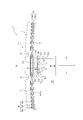
- FIG. 7 is a cross-sectional view taken along the tire equatorial plane CL (hereinafter referred to as “tire circumferential cross-sectional view”) of the tire 1 alone.
- the first noise suppressing body 3 a and the second noise suppressing body 3 b of the present embodiment are strip-shaped members extending over the entire area in the tire circumferential direction C, and any given in the tire circumferential direction C.
- the cross-sectional view in the tire width direction at the position (see FIG. 2 etc.) they have substantially the same cross-sectional outer shape.
- the first noise suppressing member 3 a and the second noise suppressing member 3 b may be provided only in a part of the tire circumferential direction C as long as the communication device 10 is held therebetween.
- the first noise suppressing member 3 a and the second noise suppressing member 3 b are provided over the entire region in the tire circumferential direction C.
- the volume of the sponge material in the tire lumen 101 can be increased as compared with the configuration in which the first noise suppressing member and the second noise suppressing member are provided only in a part of the tire circumferential direction C.
- the cavity resonance of the tire lumen 101 can be further reduced.
- each of the first noise suppressing body 3 a and the second noise suppressing body 3 b has a flat shape in a cross-sectional view in the tire width direction (see FIG. 3 and the like).
- the first noise suppressing body 3a is fixed to the tread inner surface 31 of the tire inner surface, and the maximum thickness T1 (this embodiment) in the orthogonal direction orthogonal to the tire inner surface in the tire width direction cross sectional view (see FIG. 3 etc.). Then, there is a flat shape in which the maximum length W1 in the direction along the tire inner surface (approximately equal to the maximum length in the tire width direction A in this embodiment) is larger than the maximum length in the tire radial direction B). doing.
- the thickness of the first noise reduction body 3a means the length in the orthogonal direction orthogonal to the inner surface of the tire.
- the above-mentioned maximum thickness T1 and maximum length W1 of the first noise suppressing body 3a are obtained by attaching the first noise suppressing body 3a and the second noise suppressing body 3b to the tire 1 and in a state before the rim assembly (normal temperature, It shall be measured under normal pressure).
- the maximum thickness T1 of the first noise suppressing body 3a of this embodiment is set, for example, from 5 mm to 45 mm.
- the first noise suppressing body 3a of the present embodiment has a substantially rectangular cross-sectional outer shape in a tire width direction cross-sectional view (see FIG. 3 and the like).
- the first noise suppressing body 3a of the present embodiment extends along the inner surface of the tire and is fixed to the inner surface of the tire in a cross-sectional view in the tire width direction (see FIG. 3 etc.), and the fixed surface 3a1.
- an inner side 3a2 extending along the inner surface of the tire and substantially parallel to the fixed surface 3a1, and a continuous surface with the fixed surface 3a1 and the inner side 3a2 along the inner surface of the tire (in the present embodiment, the tire width
- An end face 3a3 extending in the orthogonal direction orthogonal to the inner surface of the tire, which is located on both sides of the direction substantially equal to the direction A).
- the second noise suppressing body 3 b is stacked on the surface of the first noise suppressing body 3 a on the tire inner space 102 side.
- the second noise suppressing member 3b has a flat shape in which the maximum length W2 is larger than the maximum thickness T2 in the tire width direction sectional view (see FIG. 3 and the like).
- the thickness of the second noise suppressing body 3b is the length in the direction orthogonal to the portion where the second noise suppressing body 3b is stacked in the surface on the tire inner space 102 side of the first noise suppressing body 3a.
- the maximum thickness T2 of the second noise suppressing member 3b is a portion of the surface of the first noise suppressing member 3a on the tire inner space 102 side where the second noise suppressing member 3b is stacked (in this embodiment, It means the maximum value of the length in the direction orthogonal to a part of the inner surface 3a2.
- the maximum thickness T2 of the second noise suppressing body 3b of this embodiment is equal to the maximum length in the orthogonal direction orthogonal to the inner surface of the tire, and is substantially equal to the maximum length in the tire radial direction B.
- the length of the second noise suppressing body 3 b means the length of the second noise suppressing body 3 b in the direction along the surface of the first noise suppressing body 3 a.
- the maximum length W2 of the second noise reduction body 3b means the maximum value of the length of the second noise reduction body 3b in the direction along the surface of the first noise reduction body 3a.
- the maximum length W2 of the second noise damper 3b of the present embodiment is equal to the maximum length in the direction along the tire inner surface, and is substantially equal to the maximum length in the tire width direction A.
- the above-mentioned maximum thickness T2 and maximum length W2 of the second noise suppressing body 3b are the same as the maximum thickness T1 and maximum length W1 of the first noise suppressing body 3a. [2]
- the noise suppressing body 3b is attached, and it is assumed that the measurement is performed in a state before setting the rim (normal temperature, normal pressure).
- the second noise suppressing member 3b of the present embodiment is at least a part of the inner surface 3a2 of the first noise suppressing member 3a (a part of the inner surface 3a2 in the present embodiment) in the tire width direction sectional view (see FIG. 3 etc.) Only), and the RF tag as the communication device 10 is held between the inner side 3a2 of the first noise suppressing body 3a and the second noise suppressing body 3b.
- the entire thickness of the first noise suppressing body 3a is The shock and vibration from the tire inner surface side can be absorbed by using the same, and it is possible to further enhance the shock absorbing performance that makes it difficult for the communication device 10 to transmit the shock and vibration from the tire inner surface side.
- the second noise suppressing body 3b of the present embodiment has a substantially rectangular cross-sectional outer shape in a cross-sectional view in the tire width direction (see FIG. 3 and the like).
- the second noise suppressing body 3b of the present embodiment faces the inner side surface 3a2 of the first noise suppressing body 3a in the tire width direction cross sectional view (see FIG. 3 and the like), and extends along the tire inner surface.
- a free surface 3b2 located on the opposite side of the facing surface 3b1 and extending substantially parallel to the facing surface 3b1 along the tire inner surface, continuous with the facing surface 3b1 and the free surface 3b2 and extending along the tire inner surface
- an end surface 3b3 extending in a direction orthogonal to the inner surface of the tire is provided, which is located on both sides in the direction substantially equal to the tire width direction A).
- the minimum thickness T3 of the first noise reduction body 3a is equal to or greater than the maximum thickness T2 of the second noise reduction body 3b. More specifically, the minimum thickness T3 of the first noise suppressing body 3a of the present embodiment is thicker than the maximum thickness T2 of the second noise suppressing body 3b.
- the minimum thickness T3 of the first noise damper 3a is increased, an impact or vibration is transmitted to the communication device 10 held between the first noise damper 3a and the second noise damper 3b from the inner surface side of the tire. It can be difficult.
- the second noise suppressing body 3b only needs to suppress separation of small pieces from the surface of the sponge material, as long as it at least constitutes the surface of the sponge material facing the tire inner space 102. Therefore, the maximum thickness T2 of the second noise suppressing body 3b may be thin. As described above, it is desirable that the first noise suppressing member 3a and the second noise suppressing member 3b made of a sponge material have a predetermined volume or more in order to obtain a desired reduction effect of the cavity resonance sound.
- the minimum thickness of the first noise suppressing body 3a while the total thickness of the first noise suppressing body 3a and the second noise suppressing body 3b is equal to or more than a predetermined thickness that can ensure the desired reduction effect of the cavity resonance sound.
- the thickness of the first noise suppressing body 3a of the present embodiment is minimized at the position of the recess 11 described later, and is uniform at positions other than the recess 11. Therefore, the thickness at an arbitrary position other than the concave portion 11 of the first noise suppressing body 3a is the above-mentioned maximum thickness T1. On the other hand, the thickness at the position of the recess 11 of the first noise suppressing body 3a is the above-mentioned minimum thickness T3. Further, since the thickness of the second noise suppressing body 3b in the present embodiment is uniform, the thickness at an arbitrary position of the second noise suppressing body 3b is the above-mentioned maximum thickness T2.
- the maximum length W2 of the second noise suppressing member 3b (approximately equal to the maximum length in the tire width direction A in the present embodiment) is the maximum length W1 of the first noise suppressing member 3a ( In the present embodiment, it is shorter than the maximum length in the tire width direction A). More specifically, the second noise suppressing body 3b of the present embodiment covers only a part of the inner side surface 3a2 of the first noise suppressing body 3a, and in the tire width direction sectional view (see FIG. 3 etc.) It does not extend to the outside of the inner side surface 3a2 of the first noise suppressing body 3a in the direction along the tire inner surface.
- the second noise suppressing body 3b of this embodiment is located in the region where the inner side surface 3a2 of the first noise suppressing body 3a is located in the direction along the tire inner surface in the tire width direction cross section (see FIG. 3 etc.). Located only in. The RF tag as the communication device 10 is held at a position between the inner side surface 3a2 of the first noise suppressing body 3a and the facing surface 3b1 of the second noise suppressing body 3b.
- the length relationship between the maximum length W1 of the first noise suppressing body 3a and the maximum length W2 of the second noise suppressing body 3b is not limited to the above-described length relationship of this embodiment, and, for example, FIG.
- the maximum length W2 of the second noise suppressing member 3b may be equal to or greater than the maximum length W1 of the first noise suppressing member 3a.
- FIG. 8 shows a configuration in which the maximum length W2 of the second noise suppressing member 3b and the maximum length W1 of the first noise suppressing member 3a are substantially equal.
- FIG. 9 shows a configuration in which the maximum length W2 of the second noise damper 3b is longer than the maximum length W1 of the first noise damper 3a and is wound around the end face 3a3 of the first noise damper 3a. .
- the second noise suppressing body 3b shown in FIG. 8 covers the entire area of the inner side surface 3a2 of the first noise suppressing body 3a in the tire width direction sectional view, and the RF tag as the communication device 10 It is held between the inner side surface 3a2 of the first noise suppressing body 3a and the facing surface 3b1 of the second noise suppressing body 3b.
- the sponge material is repeatedly deformed.
- the deformation of the outer edge X of the inner surface 3a2 of the first noise damper 3a is suppressed, and the small piece of sponge material is separated from the outer edge X of the inner surface 3a2 of the first noise barrier 3a. Can be suppressed.
- the second noise suppressing body 3b shown in FIG. 9 covers at least a part of the end face 3a3 of the first noise suppressing body 3a in the tire width direction cross sectional view. That is, the second noise suppressing member 3b shown in FIG. 9 covers not only the entire area of the inner side surface 3a2 but also at least a part of the end surface 3a3 in the tire width direction sectional view. With such a configuration, as compared to the configuration in which the second noise suppressing body 3b covers only the entire inner surface 3a2 as shown in FIG. The area can be further reduced. Therefore, separation of a small piece of sponge material from the surface of the first noise suppressing body 3a can be further suppressed.
- the second noise suppressing body 3b shown in FIG. 9 covers the entire area of the inner side surface 3a2 and the end surface 3a3 of the first noise suppressing body 3a in the tire width direction cross sectional view.
- the entire area of the first noise suppressing body 3a on the tire inner space 102 side shown in FIG. 9 is covered with the second noise suppressing body 3b.
- the second noise suppressing body 3b shown in FIG. 9 is in contact with the inner surface of the tire at positions on both sides in the tire inner surface of the first noise suppressing body 3a in the tire width direction sectional view (see FIG. 9).
- the end face 3b3 of the second noise suppressing body 3b is in contact with the inner surface of the tire.
- the surface of the first noise reduction body 3a exposed to the tire inner space 102 is eliminated. Can.
- the entire surface of the first noise suppressing body 3a facing the in-tire space 102 which is easily deformed and separated into small pieces of the sponge material, is covered by the second noise suppressing body 3b. It is possible to further suppress separation of small pieces of sponge material from the surface of 3a.
- the second noise suppressing body 3b shown in FIG. 9 is, in a cross-sectional view in the tire width direction, a first stacked portion 12a stacked on the inner side surface 3a2 of the first noise suppressing body 3a and the first stacked portion 12a.
- a second laminated portion 12b continuous with one end and stacked on one end face 3a3 of the first noise suppressing body 3a and another end of the first laminated portion 12a continuously with the other end face of the first noise suppressing body 3a
- a third stacked unit 12c stacked in 3a3. Then, the RF tag as the communication device 10 is held between the inner side surface 3a2 of the first noise suppressing body 3a and the facing surface 3b1 at the position of the first laminated portion 12a of the second noise suppressing body 3b. There is.
- the thickness of the second noise suppressing body 3b shown in FIG. 9 is a length in a direction orthogonal to the inner side surface 3a2 at the position of the first laminated portion 12a (in the example shown in FIG. Means equal to the length and approximately equal to the length of the tire radial direction B). Further, the thickness of the second noise suppressing body 3b shown in FIG. 9 is a length in a direction orthogonal to the end face 3a3 at the positions of the second laminated portion 12b and the third laminated portion 12c (in the example of FIG. Approximately equal to the length of A). And maximum thickness T2 of the 2nd noise-sounding body 3b shown in FIG. 9 is a thickness of the position of the 1st lamination
- the RF tag as the communication device 10 of the present embodiment is fixed to the first noise suppressing body 3 a and the second noise suppressing body 3 b. More specifically, the RF tag as the communication device 10 of the present embodiment is fixed by an adhesive to the inner side surface 3a2 of the first noise suppressing body 3a and the facing surface 3b1 of the second noise suppressing body 3b. . Furthermore, the first noise suppressing body 3a of the present embodiment is fixed to the second noise suppressing body 3b on both sides sandwiching the communication device 10 in the direction along the tire inner surface in the tire width direction cross sectional view (see FIG. 3 etc.) It is done. More specifically, in the present embodiment, the communication device 10 in the tire width direction sectional view (see FIG.
- the adhesive is fixed on both sides in the tire width direction A of FIG.
- the tire width direction sectional view In FIG. 3 etc., it can suppress that the communication apparatus 10 moves in the direction (substantially equal to the tire width direction A in this embodiment) in alignment with a tire inner surface. Therefore, the communication device 10 can be prevented from falling off the tire lumen 101.
- each of the first noise suppressing member 3a and the second noise suppressing member 3b shown in FIGS. 3, 8 and 9 has a symmetrical shape with respect to the tire equatorial plane CL. Furthermore, the first noise suppressing member 3a and the second noise suppressing member 3b shown in FIG. 3, FIG. 8 and FIG. 9 are provided only at the position of the tread inner surface 31 in the tire inner surface. With such a configuration, even when the tire 1 is rotating at high speed, the first noise suppressing member 3a and the second noise suppressing member 3b can be formed on the tread inner surface 31 by the centrifugal force acting toward the outside in the tire radial direction B. It can be pressed.
- the communication device 10 is formed between the inner side surface 3a2 of the first noise suppressing body 3a and the opposing surface 3b1 of the second noise suppressing body 3b by the centrifugal force acting outward in the tire radial direction B. As the communication device 10 can be firmly held, the position fixability of the communication device 10 during traveling can be further improved.
- the recess 11 is formed in the first noise suppressing body 3 a, and the RF tag as the communication device 10 is accommodated in the recess 11. More specifically, the recess 11 is formed in the inner side surface 3a2 of the first noise suppressing body 3a, and the RF tag as the communication device 10 shown in FIGS. 5 and 6 is the inner side surface of the first noise suppressing body 3a. It is accommodated in the recessed part 11 of 3a2.
- the recess 11 capable of accommodating the communication device 10 in at least one of the first noise suppressing member 3 a and the second noise suppressing member 3 b, the communication device 10 is less likely to be detached from the recess 11. The position fixability of the device 10 can be further improved.
- the shape of the recess 11 for accommodating the communication device 10 is not limited to the wide shallow groove having a small depth as shown in FIGS. 3, 8 and 9, and, for example, the thin communication device 10 can be inserted.
- the recess 11 may have various shapes such as a narrow slit groove having a deep depth.
- the recessed part 11 is formed in the 1st noise suppressing body 3a, it replaces with the 1st noise suppressing body 3a, and the recessed part 11 is formed in the 2nd noise suppressing body 3b. May be formed. Furthermore, the recess 11 may be formed in each of the first noise suppressing body 3a and the second noise suppressing body 3b. In such a case, the first noise suppressing body 3a and the second noise suppressing body 3a and the second noise reduction so that one cavity for accommodating the communication device 10 is defined by the recesses 11 of both the first noise suppressing body 3a and the second noise suppressing body 3b. Stack the body 3b. In other words, the RF tag as the communication device 10 is accommodated so as to straddle both the recess 11 of the first noise suppressing body 3 a and the recess 11 of the second noise suppressing body 3 b.
- FIG. 10 is an enlarged cross-sectional view of the tread portion 1a of the cross section of the tire 21 alone in the tire width direction.
- the tire 21 of the present embodiment is different from the tire 1 of the first embodiment in the configuration of the second noise suppressing body 3b, but the other configuration is the same. Therefore, here, differences with the tire 1 of the first embodiment will be mainly described, and the description of the same configuration will be omitted.
- a convex-concave shape and a concave-convex shape are formed on the surface of the second noise suppressing body 3b on the tire inner space 102 side. More specifically, the second noise suppressing body 3b of the present embodiment and the first laminated portion 22a stacked on the inner side surface 3a2 of the first noise suppressing body 3a in the tire width direction sectional view (see FIG. 10). A second laminated portion 22b continuous with one end of the first laminated portion 22a and laminated on one end face 3a3 of the first noise damper 3a, and continuous with the other end of the first laminated portion 22a; And a third stacked portion 22c stacked on the other end face 3a3 of the noise suppressing body 3a.
- the surface on the tire inner space 102 side of the second noise suppressing body 3b of this embodiment is the free surface 3b2, and the free surface 3b2 is a surface on the inner side of the first laminated portion 22a in the tire radial direction B, It is comprised by the surface of the outer side of the tire width direction A of 2 laminated part 22b, and the surface of the outer side of the tire width direction A of 3rd laminated part 22c. Then, the surface on the inner side in the tire radial direction B of the first laminated portion 22a as the surface on the tire inner space 102 side of the second noise control body 3b extends in the tire circumferential direction C (see FIG.
- One convex rib 23 as a convex portion and a concave groove 24 as a concave portion partitioned between the two convex ribs 23 are formed. Further, one convex rib 23 is also formed on the outer surface of the second laminated portion 22b in the tire width direction A, which is the surface on the tire inner space 102 side of the second noise suppressing body 3b. Similarly, one convex rib 23 is formed also on the outer surface of the third laminated portion 22c in the tire width direction A, which is the surface on the tire inner space 102 side of the second noise control body 3b.
- the concavo-convex shape formed on the surface on the tire inner space 102 side of the second noise suppressing body 3b of the present embodiment is a plurality of convex ribs 23 and a concave groove partitioned between the plurality of convex ribs 23. And 24 are configured.
- the surface of the second noise suppressing body 3b on the side of the in-tire space 102 has a concavo-convex shape, so that the sound is easily irregularly reflected, and the cavity resonance noise can be reduced.
- the surface area of the free surface 3b2 facing the in-tire space 102 of the second noise suppressing body 3b can be increased, the heat radiation performance from the free surface 3b2 of the second noise suppressing body 3b can be enhanced.
- convex ribs 23 of this embodiment are arrange
- the configuration extends in the tire circumferential direction C (see FIG. 7).
- the present invention is not limited to this configuration, and a plurality of tires are arranged at intervals in the tire circumferential direction C (see FIG. 7). It may be configured to extend to A.
- the present invention relates to a pneumatic tire.
- 1 Pneumatic tire, 1a: tread portion, 1b: sidewall portion, 1c: bead portion, 2: rim, 2a: rim main body, 2a1: rim seat portion, 2a2: rim flange portion, 2b: disc, 3: noise control Body 3a: first noise control body 3a1: fixed surface, 3a2: inner surface, 3a3: end surface, 3b: second noise control body, 3b1: facing surface, 3b2: free surface, 3b3: end surface, 4: bead member , 4a: bead core, 4b: bead filler, 5: carcass, 5a: carcass ply, 6: belt, 6a: inclined belt, 6a1: first inclined belt layer, 6a2: second inclined belt layer, 6b: circumferential belt, 6b1 1st circumferential belt layer 6b2 2nd circumferential belt layer 6b 3 3rd circumferential belt layer 7 tread rubber 7 : Circumferential groove, 8: side rubber, 9: inner
Landscapes
- Engineering & Computer Science (AREA)
- Mechanical Engineering (AREA)
- Computer Hardware Design (AREA)
- Microelectronics & Electronic Packaging (AREA)
- Physics & Mathematics (AREA)
- General Physics & Mathematics (AREA)
- Theoretical Computer Science (AREA)
- Tires In General (AREA)
Abstract
L'invention concerne un bandage pneumatique comprenant : un premier corps de réduction de bruit réalisé à partir d'un matériau spongieux et fixé de manière fixe à la surface interne du pneumatique ; un second corps de réduction de bruit réalisé à partir d'un matériau spongieux et positionné sur le côté espace interne du pneumatique du premier corps de réduction de bruit ; et un dispositif de communication maintenu entre le premier corps de réduction de bruit et le second corps de réduction de bruit. Le second corps de réduction de bruit est plus dur que le premier corps de réduction de bruit.
Priority Applications (4)
| Application Number | Priority Date | Filing Date | Title |
|---|---|---|---|
| EP18838366.5A EP3659819B1 (fr) | 2017-07-24 | 2018-06-27 | Pneumatique |
| CN201880048768.2A CN110944852B (zh) | 2017-07-24 | 2018-06-27 | 充气轮胎 |
| US16/631,258 US11446967B2 (en) | 2017-07-24 | 2018-06-27 | Pneumatic tire |
| US17/818,000 US20220371384A1 (en) | 2017-07-24 | 2022-08-08 | Pneumatic tire |
Applications Claiming Priority (2)
| Application Number | Priority Date | Filing Date | Title |
|---|---|---|---|
| JP2017-143043 | 2017-07-24 | ||
| JP2017143043A JP6917232B2 (ja) | 2017-07-24 | 2017-07-24 | 空気入りタイヤ |
Related Child Applications (2)
| Application Number | Title | Priority Date | Filing Date |
|---|---|---|---|
| US16/631,258 A-371-Of-International US11446967B2 (en) | 2017-07-24 | 2018-06-27 | Pneumatic tire |
| US17/818,000 Continuation US20220371384A1 (en) | 2017-07-24 | 2022-08-08 | Pneumatic tire |
Publications (1)
| Publication Number | Publication Date |
|---|---|
| WO2019021730A1 true WO2019021730A1 (fr) | 2019-01-31 |
Family
ID=65040071
Family Applications (1)
| Application Number | Title | Priority Date | Filing Date |
|---|---|---|---|
| PCT/JP2018/024441 Ceased WO2019021730A1 (fr) | 2017-07-24 | 2018-06-27 | Pneumatique |
Country Status (5)
| Country | Link |
|---|---|
| US (2) | US11446967B2 (fr) |
| EP (1) | EP3659819B1 (fr) |
| JP (1) | JP6917232B2 (fr) |
| CN (1) | CN110944852B (fr) |
| WO (1) | WO2019021730A1 (fr) |
Cited By (1)
| Publication number | Priority date | Publication date | Assignee | Title |
|---|---|---|---|---|
| CN114761260A (zh) * | 2019-12-19 | 2022-07-15 | 倍耐力轮胎股份公司 | 包括监测装置的摩托车轮胎 |
Families Citing this family (11)
| Publication number | Priority date | Publication date | Assignee | Title |
|---|---|---|---|---|
| US20220055424A1 (en) * | 2018-12-10 | 2022-02-24 | Pirelli Tyre S.P.A. | Tyre with monitoring device |
| KR102023044B1 (ko) * | 2019-04-22 | 2019-09-19 | 주식회사 폼웍스 | 적층형 타이어 흡음용 프로파일 |
| JP7800190B2 (ja) * | 2021-04-22 | 2026-01-16 | 住友ゴム工業株式会社 | 空気入りタイヤ |
| JP7569283B2 (ja) * | 2021-06-30 | 2024-10-17 | 株式会社ブリヂストン | 空気入りタイヤ |
| KR102598497B1 (ko) * | 2021-09-27 | 2023-11-07 | 넥센타이어 주식회사 | 타이어 |
| JP7699531B2 (ja) * | 2021-12-13 | 2025-06-27 | 株式会社ブリヂストン | タイヤ、及びタイヤ製造方法 |
| JP7695182B2 (ja) * | 2021-12-13 | 2025-06-18 | 株式会社ブリヂストン | タイヤ |
| KR102635117B1 (ko) * | 2021-12-15 | 2024-02-13 | 넥센타이어 주식회사 | 타이어 및 타이어 제조 방법 |
| WO2025126567A1 (fr) * | 2023-12-12 | 2025-06-19 | 株式会社ブリヂストン | Pneu et pneu non pneumatique |
| JP2025093602A (ja) * | 2023-12-12 | 2025-06-24 | 株式会社ブリヂストン | タイヤ |
| CN121816277A (zh) * | 2023-12-12 | 2026-04-07 | 株式会社普利司通 | 轮胎及非充气轮胎 |
Citations (8)
| Publication number | Priority date | Publication date | Assignee | Title |
|---|---|---|---|---|
| JPS621899B2 (fr) | 1977-06-10 | 1987-01-16 | Broken Hill Pty Co Ltd | |
| JP2007176403A (ja) | 2005-12-28 | 2007-07-12 | Sumitomo Rubber Ind Ltd | タイヤ用無線タグ装着部材、空気入りタイヤならびに空気入りタイヤとリムとの組立体 |
| JP2007290699A (ja) * | 2006-04-25 | 2007-11-08 | Soc De Technologie Michelin | タイヤ監視部品用の支持体、支持体および監視部品システム、タイヤ、ならびに車輪 |
| JP2009137497A (ja) * | 2007-12-07 | 2009-06-25 | Bridgestone Corp | 電子部品取付け部材およびタイヤ内面への電子部品取り付け方法。 |
| JP2010125920A (ja) * | 2008-11-26 | 2010-06-10 | Alps Electric Co Ltd | タイヤ情報送信機の取付け構造 |
| JP2010179888A (ja) * | 2009-02-09 | 2010-08-19 | Bridgestone Corp | 空気入りタイヤ |
| JP2013112342A (ja) * | 2011-11-29 | 2013-06-10 | Goodyear Tire & Rubber Co:The | 電子装置または他の物品を空気タイヤに取り付けるシステム |
| DE102015217479A1 (de) * | 2015-09-14 | 2017-03-16 | Continental Reifen Deutschland Gmbh | Fahrzeugreifen mit einem Reifenmodul |
Family Cites Families (16)
| Publication number | Priority date | Publication date | Assignee | Title |
|---|---|---|---|---|
| US5500065A (en) * | 1994-06-03 | 1996-03-19 | Bridgestone/Firestone, Inc. | Method for embedding a monitoring device within a tire during manufacture |
| JP3621899B2 (ja) | 2001-08-28 | 2005-02-16 | 住友ゴム工業株式会社 | 空気入りタイヤとリムとの組立体 |
| JP2004276809A (ja) * | 2003-03-17 | 2004-10-07 | Honda Motor Co Ltd | 車両用車輪 |
| ES2292984T3 (es) | 2003-06-12 | 2008-03-16 | Pirelli Tyre S.P.A. | Neumatico equipado con un dispositivo de monitorizacion, y procedimiento para instalar el dispositivo sobre la superficie interior del neumatico. |
| KR101100065B1 (ko) * | 2003-08-04 | 2011-12-29 | 미쯔비시 지도샤 고교 가부시끼가이샤 | 저소음 공기 타이어 |
| JP4599150B2 (ja) * | 2004-12-14 | 2010-12-15 | 住友ゴム工業株式会社 | 電子部品の収納具を具える空気入りタイヤ |
| JP4330550B2 (ja) * | 2005-04-28 | 2009-09-16 | 住友ゴム工業株式会社 | 空気入りタイヤとリムとの組立体 |
| DE102005023974A1 (de) * | 2005-05-20 | 2006-11-23 | Continental Aktiengesellschaft | Fahrzeugreifen |
| JP4833783B2 (ja) * | 2006-09-26 | 2011-12-07 | 横浜ゴム株式会社 | タイヤ騒音低減装置及び空気入りタイヤ |
| DE102007001279B4 (de) * | 2007-01-08 | 2021-02-11 | Continental Reifen Deutschland Gmbh | Fahrzeugluftreifen mit einem Elektronikmodul |
| JP5685047B2 (ja) | 2010-10-15 | 2015-03-18 | 住友ゴム工業株式会社 | 空気入りタイヤ |
| WO2013153088A1 (fr) * | 2012-04-11 | 2013-10-17 | Huf Hülsbeck & Fürst Gmbh & Co. Kg | Module de pneu comprenant un convertisseur piézoélectrique et pneu équipé d'un tel module |
| JP6120887B2 (ja) * | 2014-04-25 | 2017-04-26 | クムホ タイヤ カンパニー インコーポレイテッドKumho Tire Co.,Inc. | 空洞共鳴音低減タイヤ |
| DE102015217472A1 (de) * | 2015-09-14 | 2017-03-16 | Continental Reifen Deutschland Gmbh | Fahrzeugreifen mit einem Reifenmodul |
| EP3431309B1 (fr) * | 2016-12-28 | 2020-05-13 | Sumitomo Rubber Industries, Ltd. | Bandage pneumatique |
| JP2018141839A (ja) * | 2017-02-27 | 2018-09-13 | 日東電工株式会社 | 吸音材 |
-
2017
- 2017-07-24 JP JP2017143043A patent/JP6917232B2/ja active Active
-
2018
- 2018-06-27 EP EP18838366.5A patent/EP3659819B1/fr active Active
- 2018-06-27 CN CN201880048768.2A patent/CN110944852B/zh active Active
- 2018-06-27 US US16/631,258 patent/US11446967B2/en active Active
- 2018-06-27 WO PCT/JP2018/024441 patent/WO2019021730A1/fr not_active Ceased
-
2022
- 2022-08-08 US US17/818,000 patent/US20220371384A1/en not_active Abandoned
Patent Citations (8)
| Publication number | Priority date | Publication date | Assignee | Title |
|---|---|---|---|---|
| JPS621899B2 (fr) | 1977-06-10 | 1987-01-16 | Broken Hill Pty Co Ltd | |
| JP2007176403A (ja) | 2005-12-28 | 2007-07-12 | Sumitomo Rubber Ind Ltd | タイヤ用無線タグ装着部材、空気入りタイヤならびに空気入りタイヤとリムとの組立体 |
| JP2007290699A (ja) * | 2006-04-25 | 2007-11-08 | Soc De Technologie Michelin | タイヤ監視部品用の支持体、支持体および監視部品システム、タイヤ、ならびに車輪 |
| JP2009137497A (ja) * | 2007-12-07 | 2009-06-25 | Bridgestone Corp | 電子部品取付け部材およびタイヤ内面への電子部品取り付け方法。 |
| JP2010125920A (ja) * | 2008-11-26 | 2010-06-10 | Alps Electric Co Ltd | タイヤ情報送信機の取付け構造 |
| JP2010179888A (ja) * | 2009-02-09 | 2010-08-19 | Bridgestone Corp | 空気入りタイヤ |
| JP2013112342A (ja) * | 2011-11-29 | 2013-06-10 | Goodyear Tire & Rubber Co:The | 電子装置または他の物品を空気タイヤに取り付けるシステム |
| DE102015217479A1 (de) * | 2015-09-14 | 2017-03-16 | Continental Reifen Deutschland Gmbh | Fahrzeugreifen mit einem Reifenmodul |
Non-Patent Citations (1)
| Title |
|---|
| See also references of EP3659819A4 |
Cited By (3)
| Publication number | Priority date | Publication date | Assignee | Title |
|---|---|---|---|---|
| CN114761260A (zh) * | 2019-12-19 | 2022-07-15 | 倍耐力轮胎股份公司 | 包括监测装置的摩托车轮胎 |
| CN114761260B (zh) * | 2019-12-19 | 2024-03-15 | 倍耐力轮胎股份公司 | 包括监测装置的摩托车轮胎 |
| US12220949B2 (en) | 2019-12-19 | 2025-02-11 | Pirelli Tyre S.P.A. | Tyre for motor-cycles comprising a monitoring device |
Also Published As
| Publication number | Publication date |
|---|---|
| US20200215858A1 (en) | 2020-07-09 |
| US11446967B2 (en) | 2022-09-20 |
| EP3659819A4 (fr) | 2021-03-24 |
| EP3659819A1 (fr) | 2020-06-03 |
| US20220371384A1 (en) | 2022-11-24 |
| CN110944852A (zh) | 2020-03-31 |
| JP2019023045A (ja) | 2019-02-14 |
| JP6917232B2 (ja) | 2021-08-11 |
| CN110944852B (zh) | 2022-09-16 |
| EP3659819B1 (fr) | 2023-01-04 |
Similar Documents
| Publication | Publication Date | Title |
|---|---|---|
| WO2019021730A1 (fr) | Pneumatique | |
| JP6853751B2 (ja) | 空気入りタイヤ | |
| JP6594504B1 (ja) | タイヤ | |
| JP6423653B2 (ja) | タイヤ | |
| JP2020055452A (ja) | タイヤ | |
| JP2020055457A (ja) | タイヤ | |
| JP2020055453A (ja) | タイヤおよびタイヤの製造方法 | |
| JP7149153B2 (ja) | タイヤ | |
| JP2010179888A (ja) | 空気入りタイヤ | |
| JP2020055459A (ja) | タイヤ | |
| CN117545640A (zh) | 轮胎 | |
| JP6672718B2 (ja) | 空気入りタイヤ | |
| JP2020055460A (ja) | タイヤ | |
| JP2023085087A (ja) | タイヤ | |
| JP6698146B1 (ja) | タイヤおよびタイヤの製造方法 | |
| JP2019014280A (ja) | 空気入りタイヤ及び組立体 | |
| JP2019014283A (ja) | 空気入りタイヤ及び組立体 | |
| WO2023276190A1 (fr) | Pneumatique | |
| JP2023085091A (ja) | タイヤ | |
| WO2023276174A1 (fr) | Pneumatique | |
| KR102598497B1 (ko) | 타이어 | |
| US20240399799A1 (en) | Pneumatic tire | |
| JP7770264B2 (ja) | タイヤ | |
| WO2023276173A1 (fr) | Pneumatique | |
| JP2019014281A (ja) | 空気入りタイヤ及び組立体 |
Legal Events
| Date | Code | Title | Description |
|---|---|---|---|
| 121 | Ep: the epo has been informed by wipo that ep was designated in this application |
Ref document number: 18838366 Country of ref document: EP Kind code of ref document: A1 |
|
| NENP | Non-entry into the national phase |
Ref country code: DE |
|
| ENP | Entry into the national phase |
Ref document number: 2018838366 Country of ref document: EP Effective date: 20200224 |