WO2019021738A1 - 繊維構造体及び繊維強化複合材 - Google Patents
繊維構造体及び繊維強化複合材 Download PDFInfo
- Publication number
- WO2019021738A1 WO2019021738A1 PCT/JP2018/024575 JP2018024575W WO2019021738A1 WO 2019021738 A1 WO2019021738 A1 WO 2019021738A1 JP 2018024575 W JP2018024575 W JP 2018024575W WO 2019021738 A1 WO2019021738 A1 WO 2019021738A1
- Authority
- WO
- WIPO (PCT)
- Prior art keywords
- formation
- fiber
- yarn
- forming
- corner
- Prior art date
- Legal status (The legal status is an assumption and is not a legal conclusion. Google has not performed a legal analysis and makes no representation as to the accuracy of the status listed.)
- Ceased
Links
Images



Classifications
-
- D—TEXTILES; PAPER
- D03—WEAVING
- D03D—WOVEN FABRICS; METHODS OF WEAVING; LOOMS
- D03D25/00—Woven fabrics not otherwise provided for
- D03D25/005—Three-dimensional woven fabrics
-
- C—CHEMISTRY; METALLURGY
- C08—ORGANIC MACROMOLECULAR COMPOUNDS; THEIR PREPARATION OR CHEMICAL WORKING-UP; COMPOSITIONS BASED THEREON
- C08J—WORKING-UP; GENERAL PROCESSES OF COMPOUNDING; AFTER-TREATMENT NOT COVERED BY SUBCLASSES C08B, C08C, C08F, C08G or C08H
- C08J5/00—Manufacture of articles or shaped materials containing macromolecular substances
- C08J5/04—Reinforcing macromolecular compounds with loose or coherent fibrous material
-
- D—TEXTILES; PAPER
- D03—WEAVING
- D03D—WOVEN FABRICS; METHODS OF WEAVING; LOOMS
- D03D11/00—Double or multi-ply fabrics not otherwise provided for
-
- B—PERFORMING OPERATIONS; TRANSPORTING
- B29—WORKING OF PLASTICS; WORKING OF SUBSTANCES IN A PLASTIC STATE IN GENERAL
- B29C—SHAPING OR JOINING OF PLASTICS; SHAPING OF MATERIAL IN A PLASTIC STATE, NOT OTHERWISE PROVIDED FOR; AFTER-TREATMENT OF THE SHAPED PRODUCTS, e.g. REPAIRING
- B29C70/00—Shaping composites, i.e. plastics material comprising reinforcements, fillers or preformed parts, e.g. inserts
- B29C70/04—Shaping composites, i.e. plastics material comprising reinforcements, fillers or preformed parts, e.g. inserts comprising reinforcements only, e.g. self-reinforcing plastics
- B29C70/06—Fibrous reinforcements only
- B29C70/10—Fibrous reinforcements only characterised by the structure of fibrous reinforcements, e.g. hollow fibres
- B29C70/16—Fibrous reinforcements only characterised by the structure of fibrous reinforcements, e.g. hollow fibres using fibres of substantial or continuous length
- B29C70/24—Fibrous reinforcements only characterised by the structure of fibrous reinforcements, e.g. hollow fibres using fibres of substantial or continuous length oriented in at least three directions forming a three-dimensional [3D] structure
-
- B—PERFORMING OPERATIONS; TRANSPORTING
- B29—WORKING OF PLASTICS; WORKING OF SUBSTANCES IN A PLASTIC STATE IN GENERAL
- B29K—INDEXING SCHEME ASSOCIATED WITH SUBCLASSES B29B, B29C OR B29D, RELATING TO MOULDING MATERIALS OR TO MATERIALS FOR MOULDS, REINFORCEMENTS, FILLERS OR PREFORMED PARTS, e.g. INSERTS
- B29K2105/00—Condition, form or state of moulded material or of the material to be shaped
- B29K2105/06—Condition, form or state of moulded material or of the material to be shaped containing reinforcements, fillers or inserts
- B29K2105/08—Condition, form or state of moulded material or of the material to be shaped containing reinforcements, fillers or inserts of continuous length, e.g. cords, rovings, mats, fabrics, strands or yarns
- B29K2105/0809—Fabrics
- B29K2105/0845—Woven fabrics
-
- B—PERFORMING OPERATIONS; TRANSPORTING
- B32—LAYERED PRODUCTS
- B32B—LAYERED PRODUCTS, i.e. PRODUCTS BUILT-UP OF STRATA OF FLAT OR NON-FLAT, e.g. CELLULAR OR HONEYCOMB, FORM
- B32B2260/00—Layered product comprising an impregnated, embedded, or bonded layer wherein the layer comprises an impregnation, embedding, or binder material
- B32B2260/04—Impregnation, embedding, or binder material
- B32B2260/046—Synthetic resin
-
- B—PERFORMING OPERATIONS; TRANSPORTING
- B32—LAYERED PRODUCTS
- B32B—LAYERED PRODUCTS, i.e. PRODUCTS BUILT-UP OF STRATA OF FLAT OR NON-FLAT, e.g. CELLULAR OR HONEYCOMB, FORM
- B32B5/00—Layered products characterised by the non- homogeneity or physical structure, i.e. comprising a fibrous, filamentary, particulate or foam layer; Layered products characterised by having a layer differing constitutionally or physically in different parts
- B32B5/22—Layered products characterised by the non- homogeneity or physical structure, i.e. comprising a fibrous, filamentary, particulate or foam layer; Layered products characterised by having a layer differing constitutionally or physically in different parts characterised by the presence of two or more layers which are next to each other and are fibrous, filamentary, formed of particles or foamed
- B32B5/24—Layered products characterised by the non- homogeneity or physical structure, i.e. comprising a fibrous, filamentary, particulate or foam layer; Layered products characterised by having a layer differing constitutionally or physically in different parts characterised by the presence of two or more layers which are next to each other and are fibrous, filamentary, formed of particles or foamed one layer being a fibrous or filamentary layer
- B32B5/26—Layered products characterised by the non- homogeneity or physical structure, i.e. comprising a fibrous, filamentary, particulate or foam layer; Layered products characterised by having a layer differing constitutionally or physically in different parts characterised by the presence of two or more layers which are next to each other and are fibrous, filamentary, formed of particles or foamed one layer being a fibrous or filamentary layer another layer next to it also being fibrous or filamentary
-
- D—TEXTILES; PAPER
- D03—WEAVING
- D03D—WOVEN FABRICS; METHODS OF WEAVING; LOOMS
- D03D1/00—Woven fabrics designed to make specified articles
-
- D—TEXTILES; PAPER
- D10—INDEXING SCHEME ASSOCIATED WITH SUBLASSES OF SECTION D, RELATING TO TEXTILES
- D10B—INDEXING SCHEME ASSOCIATED WITH SUBLASSES OF SECTION D, RELATING TO TEXTILES
- D10B2505/00—Industrial
- D10B2505/02—Reinforcing materials; Prepregs
-
- F—MECHANICAL ENGINEERING; LIGHTING; HEATING; WEAPONS; BLASTING
- F05—INDEXING SCHEMES RELATING TO ENGINES OR PUMPS IN VARIOUS SUBCLASSES OF CLASSES F01-F04
- F05D—INDEXING SCHEME FOR ASPECTS RELATING TO NON-POSITIVE-DISPLACEMENT MACHINES OR ENGINES, GAS-TURBINES OR JET-PROPULSION PLANTS
- F05D2300/00—Materials; Properties thereof
- F05D2300/60—Properties or characteristics given to material by treatment or manufacturing
- F05D2300/603—Composites; e.g. fibre-reinforced
Definitions
- the present invention relates to a fiber structure composed of a multilayer fabric, and a fiber reinforced composite material using the fiber structure as a reinforcing base.
- Fiber reinforced composites are widely used as lightweight structural materials.
- a fibrous structure is a reinforcing substrate for fiber reinforced composites.
- a fiber reinforced composite material in which the fiber structure is impregnated with a matrix resin is used as a structural material for aircraft, automobiles, buildings and the like.
- a multilayer fabric is used as a fiber structure.
- the multilayer fabric is formed, for example, by constraining a plurality of warp layers in which a plurality of warps are arranged and a plurality of weft layers in which a plurality of wefts are arranged in a stacking direction with a constraining yarn.
- the fiber structure in order to be able to use a fiber reinforced composite material in a wide range of uses, it is necessary to make the shape according to the use, for example, an L shape, a U shape, a V shape, etc.
- the fiber structure in order to produce an L-shaped fiber-reinforced composite, the fiber structure also needs to be L-shaped.
- the three-dimensional fiber structure disclosed in Patent Document 1 is formed in a shape bent in an L-shape such that two plate-like portions intersect at a corner portion.
- the three-dimensional fiber structure includes x-yarn layers, y-yarn layers and bias yarn layers arranged in parallel to one another, and thickness direction yarns and corner yarns which connect these yarn layers to one another.
- the x-yarn layer is composed of a first in-plane alignment yarn arranged in a direction along the corner.
- the y yarn layer is composed of a second in-plane alignment yarn arranged in a direction orthogonal to the first in-plane alignment yarn.
- the bias yarn layer is composed of bias yarns arranged to be inclined with respect to the first in-plane alignment yarn and the second in-plane alignment yarn.
- the thickness direction yarns extend in a direction orthogonal to the plurality of yarn layers at portions other than the corner portions, and connect the plurality of layers in the thickness direction of the three-dimensional fiber structure.
- a plurality of corner portion yarns are arranged in parallel with a plane that bisects an angle formed by two plate portions crossing each other.
- the two plate-like parts are connected to each other at the corner.
- the second in-plane alignment yarn and the bias yarn extend in a direction intersecting the corner.
- the second in-plane alignment yarn and the bias yarn are arranged across the two plate-like portions, so that the yarn is not divided at the corner portion, and the second in-plane alignment yarn and the bias yarn are The corner is reinforced.
- Patent Document 1 discloses a fiber structure in which corner portions are reinforced and which can be manufactured without using a special loom.
- the reinforcing fiber molding disclosed in Patent Document 2 is formed by laminating a plurality of rectangular base materials. Each base material has a cut portion formed by cutting one side of each of the four sides. Each base material includes a main body portion and an overlapping portion bent relative to the main body portion. By bending the base material using the notches, the overlapping portion is bent relative to the main body.
- a square box-like reinforced fiber molded object is formed by laminating a plurality of base materials so that main parts may overlap and overlapping parts may overlap.
- Each corner portion of the reinforcing fiber molding is reinforced by overlapping a plurality of overlapping portions.
- the reinforcing fiber molding of Patent Document 2 weaves a plurality of base materials, and after it is necessary to form the incisions in each base, it is necessary to overlap the main parts and the overlapping parts of those base materials, and the number of manufacturing steps is large. The manufacturing cost is high.
- An object of the present invention is to provide a fiber structure and a fiber reinforced composite material which can reinforce corner portions while suppressing the manufacturing cost.
- the fiber structure according to one aspect of the present disclosure includes a plurality of second formation portions stacked on each other, which form a first formation portion that forms a first structure portion and a second structure portion that intersects the first structure portion. And a plurality of third formations stacked one on another forming a third structure intersecting with the first structure and the second structure, and a boundary between the first structure and the second structure.
- a first corner portion which is a portion
- a second corner portion which is a boundary portion between the first structure portion and the third structure portion
- a boundary portion which is a boundary portion between the second structure portion and the third structure portion And 3 corner portions.
- Each of the first formation portion, the plurality of second formation portions, and the plurality of third formation portions includes a plurality of fiber layers stacked together, and a constraining yarn that constrains the plurality of fiber layers in the stacking direction.
- a multi-layer fabric having.
- the plurality of fiber layers are formed of a fiber layer formed of a plurality of first yarns parallel to one another, and a fiber formed of a second yarns parallel to one another extending in a direction orthogonal to the plurality of first yarns.
- the first yarn straddling the first structure portion and the second structure portion is bent at the first corner portion, and the second yarn straddles the first structure portion and the third structure portion. At least one of the first thread and the second thread that is bent at the second corner portion and straddles the second structure portion and the third structure portion is bent at the third corner portion.
- a fiber-reinforced composite material includes the above-described fiber structure and a matrix resin impregnated in the fiber structure.
- FIG. 3A The perspective view which shows the state which bend
- Fig. 5 is a side view of the fiber structure of Fig. 4; The perspective view which shows the state which bend
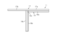
- FIG. 10 is a cross-sectional view of the fiber structure of FIG. 1 taken along line 10-10.
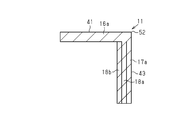
- FIG. 11 is a cross-sectional view taken along line 11-11 of the fiber structure of FIG.
- the fiber-reinforced composite material 10 is configured by compounding a fiber structure 11 composed of a multilayer fabric with a matrix resin 12.
- a matrix resin for example, an epoxy resin of a thermosetting resin is used.
- the fiber structure 11 includes a weft yarn 13 which is a first yarn, a warp yarn 14 which is a second yarn, a first restraint yarn 15a, and a second restraint yarn 15b. .
- the weft yarn 13 and the warp yarn 14 are both formed of reinforcing fibers and extend in directions orthogonal to each other.
- carbon fibers are used as the reinforcing fibers.
- the fiber structure 11 may have a three-dimensional shape in which three rectangular walls intersect (orthogonal) each other.
- the fiber structure 11 has a first structure portion 41 that constitutes a first wall of three walls.
- the first structure portion 41 has a rectangular outer surface.
- the fiber structure 11 has a second structure portion 42 which constitutes the second wall of the three walls and intersects (orthogonalizes) the first structure portion 41.
- the second structure 42 has a rectangular outer surface.
- the fiber structure 11 has a third structure 43 that constitutes the third of the three walls.
- the third structure 43 has a rectangular outer surface.
- the third structure portion 43 intersects (orthogonalizes) the first structure portion 41 and the second structure portion 42.
- the fiber structure 11 has a first corner 51 which is a boundary between the first structure 41 and the second structure 42, and a second corner which is a boundary between the first structure 41 and the third structure 43. And a third corner 53 which is a boundary between the second structure 42 and the third structure 43.
- the three-dimensional fiber structure 11 is formed by shaping the rectangular flat fiber structure 11.
- the fiber structure 11 before shaping is demonstrated.
- the fiber structure 11 before shaping is also referred to as a base material of the fiber structure 11.
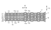
- the fiber structure 11 includes a plurality of weft layers in which a plurality of wefts 13 are arranged in parallel to one another.
- the fiber structure 11 includes a first weft layer 21, a second weft layer 22 disposed below the first weft layer 21, a third weft layer 23 disposed below the second weft layer 22, and a third weft layer 23. And a fourth weft layer 24 disposed below the third weft layer 23.
- the fiber structure 11 also includes a plurality of warp layers in which a plurality of warps 14 are arranged in parallel to one another.
- the fiber structure 11 is disposed below the first warp layer 31 and the first warp layer 31 interposed between the first weft layer 21 and the second weft layer 22, and the third weft layer 23 and the fourth weft layer And a second warp layer 32 interposed therebetween.
- the first to fourth weft layers 21 to 24 and the first to second warp layers 31 to 32 are all fiber layers.
- the first weft layer 21, the first warp layer 31, the second weft layer 22, the third weft layer 23, the second warp layer 32, and the fourth weft layer 24 are stacked in this order from top to bottom.
- the direction in which the main thread of the weft 13 extends is taken as a first direction Y1
- the direction in which the main thread of the warp 14 extends is taken as a second direction Y2.
- the direction in which the fiber layers are stacked is referred to as a stacking direction Y3.
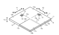
- the fiber structure 11 before shaping is provided with a first constraining portion 16 in the region from the center to the first end in the second direction Y2.
- the first restraint portion 16 includes a first weft layer 21, a first warp layer 31, a second weft layer 22, a third weft layer 23, a second warp layer 32 and a fourth weft layer 24. It is constrained in the stacking direction Y3 by the 15a and the second constraining yarn 15b.
- the first constraining yarn 15 a and the second constraining yarn 15 b have a function of holding the shape of the fiber structure 11 and are one of warps.
- the first constraining yarn 15a and the second constraining yarn 15b are made of reinforcing fibers.
- the first constraining yarns 15a and the second constraining yarns 15b are arranged in parallel to the plurality of warps 14 and are disposed at different positions in the arrangement direction of the plurality of warps 14 (first direction Y1).
- the first restraining yarn 15 a and the second restraining yarn 15 b pass through the outer surface of the weft 13 of the first weft layer 21 at a position above the warp 14 (first warp layer 31) of the uppermost layer of the fiber structure 11. It is arranged to be folded back. Also, the first constraining yarn 15a and the second constraining yarn 15b are folded back through the outer surface of the weft 13 of the fourth weft layer 24 at a position below the lowermost warp 14 (second warp layer 32). Is located in
- the fiber structure 11 has a second restraint portion 17 at a position from the center to the first end in the stacking direction Y3 in the region from the center to the second end in the second direction Y2. And a third restraint 18 at a position from the center to the second end in the stacking direction Y3.
- the second restraint portion 17 is formed by restraining the first weft layer 21, the first warp layer 31, and the second weft layer 22 in the stacking direction Y3.
- the third restraint portion 18 is formed by restraining the third weft layer 23, the second warp layer 32, and the fourth weft layer 24 in the stacking direction Y3.
- the second constraining portion 17 and the third constraining portion 18 are formed by controlling the first constraining yarn 15a and the second constraining yarn 15b at the time of weaving by the weaving machine.
- the second restraint portion 17 is restrained in the stacking direction Y3 by the first restraint yarn 15a and the second restraint yarn 15b.
- the first restraint yarn 15a and the second restraint yarn 15b are arranged to be folded back through the outer surface of the weft yarn 13 of the first weft layer 21 which is the uppermost layer of the second restraint portion 17.
- the second restraint portion 17 is penetrated in the stacking direction Y 3, and is disposed so as to be folded back through the outer surface of the weft yarn 13 of the second weft layer 22 which is the lowermost layer of the second restraint portion 17.
- the third constraining portion 18 is constrained in the stacking direction Y3 by the first constraining yarn 15a and the second constraining yarn 15b.
- the first restraint yarn 15a and the second restraint yarn 15b are arranged to be folded back through the outer surface of the weft yarn 13 of the third weft layer 23, which is the uppermost layer of the third restraint unit 18.
- the third restraint portion 18 is disposed so as to pass through in the stacking direction Y3 and to be folded back through the outer surface of the weft yarn 13 of the fourth weft layer 24 which is the lowermost layer of the third restraint portion 18.
- the second constraining portion 17 is connected to the first constraining portion 16 in a region from the center to the first end in the first direction Y1.
- the second constraining portion 17 is separated from the first constraining portion 16 in a region from the center to the second end in the first direction Y1.
- the warp threads 14 of the first warp layer 31 extend in the second direction Y2 across the first constraining portion 16 and the second constraining portion 17.
- the first constraining portion 16 and the second constraining portion 17 extend in the second direction. It is connected to Y2.
- the third constraining portion 18 is connected to the first constraining portion 16 in the second direction Y2.
- the warp yarn 14 of the second warp layer 32 extends in the second direction Y2 across the first restraint portion 16 and the third restraint portion 18, and the first restraint portion 16 and the third restraint portion 18 extend in the second direction. It is connected to Y2.
- the third constraining portion 18 is divided at the center of the first direction Y1.
- first formation portion 16a that forms the first structure portion 41.
- the first formation portion 16a is rectangular when viewed in the stacking direction Y3.
- the first weft layer 21, the first warp layer 31, the second weft layer 22, the third weft layer 23, the second warp layer 32, and the fourth weft layer 24 It is restrained in the stacking direction Y3 by 15a and the second constraining yarn 15b. Therefore, the first formation portion 16a has six fiber layers.
- a portion from the center to the second end in the first direction Y1 is a second formation portion 16b that forms the second structure portion 42.
- the second formation portion 16 b is rectangular when viewed in the stacking direction Y3.
- the first weft layer 21, the first warp layer 31, the second weft layer 22, the third weft layer 23, the second warp layer 32, and the fourth weft layer 24 It is restrained in the stacking direction Y3 by 15a and the second constraining yarn 15b. Therefore, the second formation portion 16 b has six fiber layers.
- the fiber structure 11 includes a bent portion 16 c at the center of the first constraining portion 16 in the first direction Y1.
- the bent portion 16c is a boundary between the first forming portion 16a and the second forming portion 16b, and the first corner portion 51 is formed along the bent portion 16c. Therefore, in the bent portion 16c forming the first corner portion 51, the first formation portion 16a and the second formation portion 16b are connected.
- the bent portion 16c is also an edge portion of each of the first formation portion 16a and the second formation portion 16b.
- a portion from the center to the first end in the first direction Y1 is a third formation portion 17a forming the third structure portion 43.
- the third formation portion 17a is rectangular as viewed in the stacking direction Y3.
- the first weft layer 21, the first warp layer 31, and the second weft layer 22 are constrained in the stacking direction Y3 by the first constraining yarn 15a and the second constraining yarn 15b. Therefore, the third formation portion 17a has three fiber layers.
- a portion from the center to the second end in the first direction Y1 is a second formation portion 17b forming the second structure portion 42.
- the second formation portion 17 b is rectangular as viewed in the stacking direction Y3.
- the first weft layer 21, the first warp layer 31, and the second weft layer 22 are constrained in the stacking direction Y3 by the first constraining yarn 15a and the second constraining yarn 15b. Therefore, the second formation portion 17 b has three fiber layers.
- the fiber structure 11 includes a bent portion 17 c at the center of the second constraining portion 17 in the first direction Y1.
- the bent portion 17c is a boundary portion between the third formation portion 17a and the second formation portion 17b.
- the third corner portion 53 is formed along the bent portion 17c. Therefore, in the bent portion 17c forming the third corner portion 53, the third formation portion 17a and the second formation portion 17b are connected.
- the bent portion 17c is also an edge portion of each of the third formation portion 17a and the second formation portion 17b.
- a portion from the center to the first end in the first direction Y1 is a third formation portion 18a that forms the third structure portion 43.
- the third formation portion 18a is rectangular when viewed in the stacking direction Y3.
- the third weft layer 23, the second warp layer 32, and the fourth weft layer 24 are constrained in the stacking direction Y3 by the first constraining yarn 15a and the second constraining yarn 15b. Therefore, the third formation portion 18a has three fiber layers.
- a portion from the center to the second end in the first direction Y1 is a third formation portion 18b that forms the third structure portion 43.
- the third formation portion 18 b is rectangular as viewed in the stacking direction Y3.
- the third weft layer 23, the second warp layer 32, and the fourth weft layer 24 are restrained in the stacking direction Y3 by the first constraining yarn 15a and the second constraining yarn 15b. Therefore, the third formation portion 18b has three fiber layers.
- the fiber structure 11 includes a cut portion 18 c at the center of the third restraint portion 18 in the first direction Y1.
- the cut portion 18c is a boundary between the third formation portion 18a and the third formation portion 18b, and divides the both.
- the incised portion 18 c is formed by cutting the fiber structure 11 after weaving the fiber structure 11 including the first restraint portion 16, the second restraint portion 17, and the third restraint portion 18 with a loom.
- the fiber structure 11 includes a bent portion 19a which is a boundary between the first forming portion 16a and the third forming portion 17a in the second direction Y2.
- a second corner 52 is formed along the bent portion 19a. Therefore, in the bent portion 19a forming the second corner portion 52, the first formation portion 16a and the third formation portion 17a are connected.
- the bent portion 19a is also an edge portion of each of the first forming portion 16a and the third forming portion 17a.
- the fiber structure 11 is provided with the cut part 19b in the boundary of the 2nd formation part 16b in the 2nd direction Y2, and the 2nd formation part 17b.
- the cut portion 19 b is formed by cutting the fiber structure 11 after weaving the fiber structure 11 including the first restraint portion 16, the second restraint portion 17, and the third restraint portion 18 with a loom.
- the fiber structure 11 includes a bent portion 19c which is a boundary between the second forming portion 16b and the third forming portion 18b in the second direction Y2.
- the third corner portion 53 is formed along the bent portion 19c. Therefore, in the bent portion 19c forming the third corner portion 53, the second formation portion 16b and the third formation portion 18b are connected.
- the bent portion 19c is also an edge portion of each of the second formation portion 16b and the third formation portion 18b.
- the first formation portion 16a, the second formation portions 16b and 17b, and the third formation portions 17a, 18a and 18b have the same size.
- one second forming portion 16 b is connected by the weft 13 to the bending portion 16 c in the first forming portion 16 a, and one bending portion 19 c in the second forming portion 16 b
- the third forming portion 18 b is connected by the warp 14.
- the remaining two third forming portions 17a and 18a are connected by the warp 14 to the bending portion 19a of the first forming portion 16a, and the other second forming portion is connected to the bending portion 17c of one third forming portion 17a.
- 17b are connected by the weft 13.
- the warp 14 extends in the second direction Y2 across the first forming portion 16a of the first constraining portion 16 and the third forming portion 17a of the second constraining portion 17,
- the first formation portion 16a and the third formation portion 17a are connected in the second direction Y2.
- the warp 14 extends in the second direction Y2 across the first formation portion 16a and the third formation portion 18a of the third restraint portion 18.
- the first formation portion 16a and the third formation portion 18a It is connected to 2 directions Y2.
- the warp 14 extends in the second direction Y2 across the second formation portion 16b of the first restraint portion 16 and the third formation portion 18b of the third restraint portion 18, and the second formation portion 16b and the second formation portion 16b
- the third formation portion 18 b is connected to the second direction Y2.
- the weft thread 13 extends in the first direction Y1 across the first formation portion 16a and the second formation portion 16b of the first restraint portion 16, and the first formation portion 16a and the second formation portion 16b extend in the first direction. It is connected to Y1.
- the weft 13 extends in the first direction Y1 across the third forming portion 17a and the second forming portion 17b of the second restraint portion 17, and the third forming portion 17a and the second forming portion 17b
- One direction is connected to Y1.
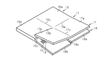
- the first constraining portion 16 is bent at a right angle at the bending portion 16c.
- the second forming portion 16b is shaped so as to be orthogonal to the first forming portion 16a, and the third forming portion 18b connected to the second forming portion 16b is also orthogonal to the second constraining portion 17. Shaped into a state.
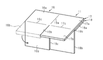
- the third forming portion 18b is bent from the bending portion 19c, and is shaped such that the third forming portion 18b is orthogonal to the second forming portion 16b.
- the second restraint portion 17 is bent from the bent portion 19a, and is shaped such that the third formation portion 17a is orthogonal to the first formation portion 16a.
- the second formation portion 17b connected to the third formation portion 17a is also shaped in a state orthogonal to the first formation portion 16a.
- the second restraint portion 17 is bent from the bent portion 17c, and the second formation portion 17b is shaped so as to be orthogonal to the third formation portion 17a.
- the 1st structure part 41 is formed of the 1st formation part 16a, the 2nd formation part 16b and the 2nd formation part 17b of the 2nd restraint part 17 are laminated, and the 1st is formed.
- the two structural parts 42 are formed.
- the third formation portion 17a of the second restraint portion 17, the third formation portion 18a of the third restraint portion 18 and the third formation portion 18b are stacked to form the third structure portion 43. Be done. Next, the action of the fiber structure 11 will be described.
- the first structure portion 41 is formed by the first formation portion 16 a itself, and the first weft layer 21, the first warp layer 31, the second weft layer 22, The third weft layer 23, the second warp layer 32, and the fourth weft layer 24 are formed. Therefore, the first structure portion 41 has six fiber layers.
- the second structure portion 42 is formed by the second formation portion 16 b of the first restraint portion 16 and the second formation portion 17 b of the second restraint portion 17. Therefore, the second structure portion 42 includes the first weft layer 21, the first warp layer 31, the second weft layer 22, the third weft layer 23, the second warp layer 32, and the fourth weft layer of the second forming portion 16b. 24 and the first weft layer 21, the first warp layer 31, and the second weft layer 22 of the second forming portion 17 b. Thus, the second structure 42 has nine fiber layers.
- the third structure portion 43 is formed by the third formation portion 17 a of the second restraint portion 17 and the third formation portion 18 a and the third formation portion 18 b of the third restraint portion 18. . Therefore, the third structure portion 43 includes the first weft layer 21, the first warp layer 31, and the second weft layer 22 of the third forming portion 17a, and the third weft layer 23, the second warp of the third forming portion 18a. The layer 32 and the fourth weft layer 24 and the third weft layer 23, the second warp layer 32 and the fourth weft layer 24 of the third forming portion 18 b are formed. Thus, the third structural portion 43 has nine fiber layers.
- the fiber structure 11 includes a first corner portion 51 which is a boundary portion between the first structure portion 41 and the second structure portion 42.
- the first corner portion 51 is bent along the bent portion 16c.
- the weft yarn 13 extending along the first direction Y1 is bent. Therefore, the first structural portion 41 and the second structural portion 42 are connected by the weft 13 and have continuity.
- the fiber structure 11 includes a second corner 52 which is a boundary between the first structural portion 41 and the third structural portion 43.
- the second corner portion 52 is bent along the bent portion 19a.
- the warp 14 extending along the second direction Y2 is bent. Therefore, the 1st structure part 41 and the 3rd structure part 43 are connected by the warp yarn 14, and have continuity.
- the fiber structure 11 includes a third corner 53 that is a boundary between the second structure 42 and the third structure 43.
- the third corner portion 53 is bent along the bent portion 17c.
- the weft 13 and the warp 14 are bent. Therefore, the second structural portion 42 and the third structural portion 43 are connected by the weft 13 and the warp 14 and have continuity.
- the fiber structure 11 before shaping is formed of a multi-layered fabric, and includes the first restraint portion 16, the second restraint portion 17, and the third restraint portion 18.
- the fiber structure 11 can be woven by a weaving machine using the weft yarn 13, the warp yarn 14, the first constraining yarn 15a and the second constraining yarn 15b.
- the three-dimensional fiber structure 11 can be formed by shaping the fiber structures 11. Therefore, it is not necessary to manufacture a fiber structure, by overlapping a plurality of base materials, and the fiber structure 11 can be easily manufactured. Moreover, compared with the case where it weaves using a special loom, manufacturing cost can be held down.
- the continuity of the first corner portion 51 is secured by the weft 13, and the continuity of the second corner portion 52 is secured by the warp 14. Further, the third corner portion 53 is secured by the weft 13 and the warp 14. Therefore, the yarn is not divided at the first to third corner portions 51 to 53, and the first to third corner portions 51 to 53 can be reinforced.
- each of the second structure portion 42 and the third structure portion 43 has nine fiber layers. Therefore, the number of fiber layers of each of the second structure portion 42 and the third structure portion 43 is larger than the number of fiber layers of the first structure portion 41, and the second structure portion 42 and the third structure portion 43 can be reinforced. .
- the warp 14 extends across the second formation 16b of the first restraint 16 and the third formation 18b of the third restraint 18, and forms a second formation with the third formation 17a of the second restraint 17.
- a weft thread 13 extends across the portion 17b. Therefore, when the second structural portion 42 and the third structural portion 43 are formed, the weft 13 and the warp 14 straddle the third corner portion 53, and the third corner portion 53 can be reinforced with two types of yarn.
- the first to third restraint portions 16 to 18 are restrained in the stacking direction Y3 by the first constraining yarn 15a and the second constraining yarn 15b. Therefore, even if the fiber structure 11 has the notches 18 c and 19 b in order to shape the fiber structure 11, the fiber structure 11 does not separate, and the shaping can be easily performed.
- the plurality of fiber layers are constrained in the stacking direction Y3 by the first constraining yarn 15a and the second constraining yarn 15b.
- the fiber structure 11 can be woven by a loom. Therefore, for example, unlike the case of manufacturing the fiber structure 11 by laminating the fiber layers after manufacturing the fiber layers one by one, the fiber structure 11 in which a plurality of fiber layers are restrained can be easily manufactured.
- the above embodiment may be modified as follows.
- the number of fiber layers of the second formation portion 16b may be four. That is, the number of fiber layers of the second formation portion 16b may be smaller than that of the first formation portion 16a.
- the number of fiber layers of each of the third formation portion 17a and the second formation portion 17b of the second restraint portion 17 is two, and each of the third formation portion 18a and the third formation portion 18b of the third restraint portion 18 The number of fiber layers is 2.
- the first structure portion 41 is formed by the first formation portion 16a itself
- the second structure portion 42 is formed by the second formation portion 16b and the second formation portion 17b
- the third structure portion 43 is formed by the second restraint.
- the third forming portion 17 a of the portion 17 and the third forming portion 18 a and the third forming portion 18 b of the third constraining portion 18 are formed.
- the first structural portion 41, the second structural portion 42, and the third structural portion 43 each have six fiber layers, the first to third structural portions 41 to 43 have the same strength. You can
- the strength of the first to third structural portions 41 to 43 can be changed by appropriately changing the number of fiber layers.
- a yarn that spans the second structural portion 42 and the third structural portion 43 at the third corner portion 53 with the third constraining portion 18 as the third forming portion 18a only is a third forming portion 17a and the second forming portion 17b.
- only the weft yarn 13 may be used.
- the formation part which forms another structure part may be connected with four outer edge parts of the flat fiber structure 11.
- the fiber layer may be formed by plain weave, satin weave, or twill weave.
- the numbers of weft layers and warp layers to be laminated may be changed as appropriate.
- the kind of matrix resin can be selected arbitrarily.
- the first structural portion 41, the second structural portion 42, and the third structural portion 43 have a rectangular shape, but are not limited thereto.
- the first structure portion 41, the second structure portion 42, and the third structure portion 43 may have any shape such as a trapezoidal shape or a circular shape.
Landscapes
- Engineering & Computer Science (AREA)
- Textile Engineering (AREA)
- Chemical & Material Sciences (AREA)
- Manufacturing & Machinery (AREA)
- Materials Engineering (AREA)
- Health & Medical Sciences (AREA)
- Chemical Kinetics & Catalysis (AREA)
- Medicinal Chemistry (AREA)
- Polymers & Plastics (AREA)
- Organic Chemistry (AREA)
- Woven Fabrics (AREA)
- Reinforced Plastic Materials (AREA)
Abstract
繊維構造体は、第1構造部と第2構造部との境界部分である第1コーナ部と、第1構造部と第3構造部との境界部分である第2コーナ部と、第2構造部と第3構造部との境界部分である第3コーナ部と、を備える。第1構造部と第2構造部とに跨る第1の糸は第1コーナ部で屈曲している。第1構造部と第3構造部とに跨る第2の糸は第2コーナ部で屈曲している。第2構造部と第3構造部とに跨る、第1の糸及び第2の糸のうち少なくとも一方が第3コーナ部で屈曲している。
Description
本発明は、多層織物により構成された繊維構造体、及び該繊維構造体を強化基材とした繊維強化複合材に関する。
繊維強化複合材は軽量の構造材料として広く使用されている。繊維強化複合材用の強化基材として繊維構造体がある。この繊維構造体にマトリックス樹脂を含浸させた繊維強化複合材は、航空機、自動車及び建築物等の構造材として用いられている。また、繊維構造体としては、多層織物が使用されている。多層織物は、例えば複数本の経糸が配列された複数の経糸層と、複数本の緯糸が配列された複数の緯糸層とを拘束糸で積層方向に拘束することにより形成されている。
ところで、繊維強化複合材を幅広い用途に使用可能とするためには、その用途に合わせた形状、例えば、L字状、U字状、V字状等にする必要がある。例えば、L字状の繊維強化複合材を製造するには、繊維構造体もL字状である必要がある。例えば、特許文献1に開示の三次元繊維構造体は、2枚の板状部がコーナ部で交差するように、L字状に屈曲した形状に形成されている。この三次元繊維構造体は、互いに平行に配列されたx糸層、y糸層及びバイアス糸層と、これらの糸層を相互に結合する厚さ方向糸及びコーナ部用糸とを含む。
x糸層は、コーナ部に沿った方向に配列された第1の面内配列糸により構成される。y糸層は、第1の面内配列糸と直交する方向に配列された第2の面内配列糸により構成される。バイアス糸層は、第1の面内配列糸及び第2の面内配列糸に対して傾斜するように配列されたバイアス糸により構成される。厚さ方向糸は、コーナ部以外の部分では、複数の糸層と直交する方向に延びて、三次元繊維構造体の厚さ方向に複数の層を結合している。コーナ部用糸は、2つの板状部が交わるって形成する角を2等分する面と平行に複数配列されている。
L字状の三次元繊維構造体において、2枚の板状部は、コーナ部で互いに接続している。第2の面内配列糸及びバイアス糸はコーナ部と交差する方向に延びている。そして、第2の面内配列糸及びバイアス糸が2つの板状部に跨って配列されることにより、コーナ部で糸が分断されることがなく、第2の面内配列糸及びバイアス糸によってコーナ部が補強されている。
しかし、特許文献1の三次元構造体は、特殊な織機でしか製造できず、製造コストが嵩む。特許文献2には、コーナ部を補強した繊維構造体であり、特殊な織機を使用せずに製造できる繊維構造体が開示されている。特許文献2に開示の強化繊維成形体は、複数の四角形状の基材を積層して形成されている。各基材は、四辺それぞれを一箇所ずつ切り込んで形成した切込み部を有する。各基材は、本体部と、本体部に対し屈曲した重ね部とを備える。切込み部を利用して基材を折り曲げることによって、重ね部が本体部に対し屈曲する。
そして、四角箱状の強化繊維成形体は、本体部同士が重なり合うとともに重ね部同士が重なり合うように、複数の基材を積層することによって形成されている。強化繊維成形体の各コーナ部は、複数の重ね部が重なり合うことによって補強されている。
特許文献2の強化繊維成形体は、複数枚の基材を織製し、各基材に切込み部を形成した後、それら基材の本体部及び重ね部を重ねる必要があり、製造工数が多く製造コストが嵩む。
本発明の目的は、製造コストを抑えつつコーナ部を補強できる繊維構造体及び繊維強化複合材を提供することにある。
本開示の一態様の繊維構造体は、第1構造部を形成する第1形成部と、前記第1構造部と交差する第2構造部を形成する、互いに積層される複数の第2形成部と、前記第1構造部及び前記第2構造部と交差する第3構造部を形成する、互いに積層される複数の第3形成部と、前記第1構造部と前記第2構造部との境界部分である第1コーナ部と、前記第1構造部と前記第3構造部との境界部分である第2コーナ部と、前記第2構造部と前記第3構造部との境界部分である第3コーナ部と、を備える。前記第1形成部、前記複数の第2形成部、及び前記複数の第3形成部の各々は、互いに積層される複数の繊維層と、前記複数の繊維層を積層方向に拘束する拘束糸と、を有する多層織物によって構成される。前記複数の繊維層は、互いに平行な複数の第1の糸により形成される繊維層と、前記複数の第1の糸と直交する方向に延びる、互いに平行な第2の糸により形成される繊維層とを含む。前記第1構造部と前記第2構造部とに跨る前記第1の糸が前記第1コーナ部で屈曲し、前記第1構造部と前記第3構造部とに跨る前記第2の糸が前記第2コーナ部で屈曲し、前記第2構造部と前記第3構造部とに跨る、前記第1の糸及び前記第2の糸のうち少なくとも一方が前記第3コーナ部で屈曲している。
本開示の一態様の繊維強化複合材は、上記繊維構造体と、前記繊維構造体に含浸されたマトリックス樹脂と、を含む。
以下、繊維構造体及び繊維強化複合材を具体化した一実施形態を図1~図11にしたがって説明する。
図1に示すように、繊維強化複合材10は、多層織物によって構成される繊維構造体11がマトリックス樹脂12に複合化されて構成されている。マトリックス樹脂としては、例えば、熱硬化性樹脂のエポキシ樹脂が使用される。
図1に示すように、繊維強化複合材10は、多層織物によって構成される繊維構造体11がマトリックス樹脂12に複合化されて構成されている。マトリックス樹脂としては、例えば、熱硬化性樹脂のエポキシ樹脂が使用される。
図2に示すように、繊維構造体11は、第1の糸である緯糸13と、第2の糸である経糸14と、第1の拘束糸15aと、第2の拘束糸15bとを備える。緯糸13及び経糸14は、共に強化繊維によって形成され、互いに直交する方向に延びている。この実施形態では強化繊維として炭素繊維が使用されている。
図1に示すように、繊維構造体11は、三つの矩形壁が互いに交差(直交)した立体形状を有してもよい。繊維構造体11は、三つの壁のうちの第1壁を構成する第1構造部41を有する。第1構造部41は矩形の外面を有する。繊維構造体11は、三つの壁のうちの第2壁を構成し、かつ第1構造部41に対し交差(直交)する第2構造部42を有する。第2構造部42は矩形の外面を有する。繊維構造体11は、三つの壁のうちの第3壁を構成する第3構造部43を有する。第3構造部43は矩形の外面を有する。第3構造部43は、第1構造部41及び第2構造部42に対し交差(直交)する。
繊維構造体11は、第1構造部41と第2構造部42との境界部分である第1コーナ部51と、第1構造部41と第3構造部43との境界部分である第2コーナ部52と、第2構造部42と第3構造部43との境界部分である第3コーナ部53と、を有する。
立体形状の繊維構造体11は、矩形平板形状の繊維構造体11を賦形して形成されている。ここで、賦形する前の繊維構造体11について説明する。賦形する前の繊維構造体11を繊維構造体11の母材ともいう。
図2に示すように、繊維構造体11は、複数本の緯糸13が互いに平行に配列された緯糸層を複数備える。繊維構造体11は、第1緯糸層21と、第1緯糸層21より下方に配置された第2緯糸層22と、第2緯糸層22より下方に配置された第3緯糸層23と、第3緯糸層23より下方に配置された第4緯糸層24と、を有する。また、繊維構造体11は、複数本の経糸14が互いに平行に配列された経糸層を複数備える。
繊維構造体11は、第1緯糸層21と第2緯糸層22の間に介在する第1経糸層31と、第1経糸層31より下方に配置され、第3緯糸層23と第4緯糸層24の間に介在する第2経糸層32と、を有する。第1~第4緯糸層21~24及び第1~第2経糸層31~32は、いずれも繊維層である。第1緯糸層21、第1経糸層31、第2緯糸層22、第3緯糸層23、第2経糸層32、及び第4緯糸層24は上から下へこの順番で積層されている。
図3Aに示すように、平板形状の繊維構造体11すなわち母材において、緯糸13の糸主軸が延びる方向を第1方向Y1とし、経糸14の糸主軸が延びる方向を第2方向Y2とする。また、平板形状の繊維構造体11において、繊維層が積み重なった方向を積層方向Y3とする。
賦形する前の繊維構造体11は、第2方向Y2における中央から第1端までの領域に第1拘束部16を備える。第1拘束部16は、第1緯糸層21、第1経糸層31、第2緯糸層22、第3緯糸層23、第2経糸層32、及び第4緯糸層24が、第1の拘束糸15a及び第2の拘束糸15bにより積層方向Y3に拘束されて形成されている。
図2に示すように、第1の拘束糸15a及び第2の拘束糸15bは、繊維構造体11の形状を保持する機能を有し、経糸の一つである。また、第1の拘束糸15a及び第2の拘束糸15bは、強化繊維で構成されている。第1の拘束糸15a及び第2の拘束糸15bは、複数の経糸14と平行に配列されるとともに、複数の経糸14の配列方向(第1方向Y1)において互いに異なる位置に配置されている。
第1の拘束糸15a及び第2の拘束糸15bは、繊維構造体11の最上層の経糸14(第1経糸層31)より上の位置で、第1緯糸層21の緯糸13の外面を通って折り返すように配置されている。また、第1の拘束糸15a及び第2の拘束糸15bは、最下層の経糸14(第2経糸層32)より下の位置で、第4緯糸層24の緯糸13の外面を通って折り返すように配置されている。
図3A又は図3Bに示すように、繊維構造体11は、第2方向Y2における中央から第2端までの領域のうち、積層方向Y3における中央から第1端までの位置に第2拘束部17を備え、積層方向Y3における中央から第2端までの位置に第3拘束部18を備える。第2拘束部17は、第1緯糸層21、第1経糸層31、及び第2緯糸層22が積層方向Y3に拘束されて形成される。第3拘束部18は、第3緯糸層23、第2経糸層32、及び第4緯糸層24が積層方向Y3に拘束されて形成される。第2拘束部17及び第3拘束部18は、織機による製織の際、第1の拘束糸15a及び第2の拘束糸15bを制御することで形成される。
図2に示すように、第2拘束部17は、第1の拘束糸15a及び第2の拘束糸15bによって積層方向Y3に拘束されている。第2拘束部17では、第1の拘束糸15a及び第2の拘束糸15bは、第2拘束部17の最上層である第1緯糸層21の緯糸13の外面を通って折り返すように配置され、第2拘束部17を積層方向Y3に貫通し、第2拘束部17の最下層である第2緯糸層22の緯糸13の外面を通って折り返すように配置されている。
第3拘束部18は、第1の拘束糸15a及び第2の拘束糸15bによって積層方向Y3に拘束されている。第3拘束部18では、第1の拘束糸15a及び第2の拘束糸15bは、第3拘束部18の最上層である第3緯糸層23の緯糸13の外面を通って折り返すように配置され、第3拘束部18を積層方向Y3に貫通し、第3拘束部18の最下層である第4緯糸層24の緯糸13の外面を通って折り返すように配置されている。
図3A又は図3Bに示すように、第1方向Y1における中央から第1端までの領域では、第2拘束部17は第1拘束部16と繋がっている。第1方向Y1における中央から第2端までの領域では、第2拘束部17は第1拘束部16と分断されている。第1経糸層31の経糸14は、第1拘束部16と第2拘束部17とに跨って第2方向Y2に延びており、第1拘束部16と第2拘束部17とは第2方向Y2に繋がっている。
また、第3拘束部18は、第2方向Y2に第1拘束部16と繋がっている。第2経糸層32の経糸14は、第1拘束部16と第3拘束部18とに跨って第2方向Y2に延びており、第1拘束部16と第3拘束部18とは第2方向Y2に繋がっている。なお、第3拘束部18は、第1方向Y1の中央で分断されている。
繊維構造体11の第1拘束部16のうち、第1方向Y1における中央から第1端までの部分は、第1構造部41を形成する第1形成部16aである。第1形成部16aは積層方向Y3から見て矩形である。第1形成部16aでは、第1緯糸層21、第1経糸層31、第2緯糸層22、第3緯糸層23、第2経糸層32、及び第4緯糸層24が、第1の拘束糸15a及び第2の拘束糸15bにより積層方向Y3に拘束されている。したがって、第1形成部16aは6つの繊維層を有する。
繊維構造体11の第1拘束部16のうち、第1方向Y1における中央から第2端までの部分は、第2構造部42を形成する第2形成部16bである。第2形成部16bは積層方向Y3から見て矩形である。第2形成部16bでは、第1緯糸層21、第1経糸層31、第2緯糸層22、第3緯糸層23、第2経糸層32、及び第4緯糸層24が、第1の拘束糸15a及び第2の拘束糸15bにより積層方向Y3に拘束されている。したがって、第2形成部16bは、6つの繊維層を有する。
繊維構造体11は、第1拘束部16の第1方向Y1における中央に折り曲げ部16cを備える。折り曲げ部16cは、第1形成部16aと第2形成部16bとの境界部分であり、折り曲げ部16cに沿って第1コーナ部51が形成される。したがって、第1コーナ部51を形成する折り曲げ部16cにおいて、第1形成部16aと第2形成部16bとが繋がっている。折り曲げ部16cは、第1形成部16a及び第2形成部16bの各々の縁部でもある。
繊維構造体11の第2拘束部17のうち、第1方向Y1における中央から第1端までの部分は、第3構造部43を形成する第3形成部17aである。第3形成部17aは、積層方向Y3から見て矩形である。第3形成部17aでは、第1緯糸層21、第1経糸層31、及び第2緯糸層22が、第1の拘束糸15a及び第2の拘束糸15bにより積層方向Y3に拘束されている。したがって、第3形成部17aは3つの繊維層を有する。
繊維構造体11の第2拘束部17のうち、第1方向Y1における中央から第2端までの部分は、第2構造部42を形成する第2形成部17bである。第2形成部17bは、積層方向Y3から見て矩形である。第2形成部17bでは、第1緯糸層21、第1経糸層31、及び第2緯糸層22が、第1の拘束糸15a及び第2の拘束糸15bにより積層方向Y3に拘束されている。したがって、第2形成部17bは3つの繊維層を有する。
繊維構造体11は、第2拘束部17の第1方向Y1における中央に折り曲げ部17cを備える。折り曲げ部17cは、第3形成部17aと第2形成部17bとの境界部分である。折り曲げ部17cに沿って第3コーナ部53が形成される。したがって、第3コーナ部53を形成する折り曲げ部17cにおいて、第3形成部17aと第2形成部17bとが繋がっている。折り曲げ部17cは、第3形成部17a及び第2形成部17bの各々の縁部でもある。
繊維構造体11の第3拘束部18のうち、第1方向Y1における中央から第1端までの部分は、第3構造部43を形成する第3形成部18aである。第3形成部18aは、積層方向Y3から見て矩形である。第3形成部18aでは、第3緯糸層23、第2経糸層32、及び第4緯糸層24が、第1の拘束糸15a及び第2の拘束糸15bにより積層方向Y3に拘束されている。したがって、第3形成部18aは3つの繊維層を有する。
繊維構造体11の第3拘束部18のうち、第1方向Y1における中央から第2端までの部分は、第3構造部43を形成する第3形成部18bである。第3形成部18bは、積層方向Y3から見て矩形である。第3形成部18bでは、第3緯糸層23、第2経糸層32、及び第4緯糸層24が、第1の拘束糸15a及び第2の拘束糸15bにより積層方向Y3に拘束されている。したがって、第3形成部18bは3つの繊維層を有する。
繊維構造体11は、第3拘束部18の第1方向Y1における中央に切込み部18cを備える。切込み部18cは、第3形成部18aと第3形成部18bとの境界であり、両者を分断する。なお、切込み部18cは、第1拘束部16、第2拘束部17、及び第3拘束部18を備える繊維構造体11を織機で製織した後に、繊維構造体11を切断して形成される。
繊維構造体11は、第2方向Y2における第1形成部16aと第3形成部17aとの境界部分である折り曲げ部19aを備える。この折り曲げ部19aに沿って第2コーナ部52が形成される。したがって、第2コーナ部52を形成する折り曲げ部19aにおいて、第1形成部16aと第3形成部17aとが繋がっている。折り曲げ部19aは、第1形成部16a及び第3形成部17aの各々の縁部でもある。
また、繊維構造体11は、第2方向Y2における第2形成部16bと第2形成部17bとの境界に切込み部19bを備える。切込み部19bは、第1拘束部16、第2拘束部17、及び第3拘束部18を備える繊維構造体11を織機で製織した後に、繊維構造体11を切断して形成される。
繊維構造体11は、第2方向Y2における第2形成部16bと第3形成部18bとの境界部分である折り曲げ部19cを備える。この折り曲げ部19cに沿って第3コーナ部53が形成される。したがって、第3コーナ部53を形成する折り曲げ部19cにおいて、第2形成部16bと第3形成部18bとが繋がっている。折り曲げ部19cは、第2形成部16b及び第3形成部18bの各々の縁部でもある。第1形成部16aと、第2形成部16b,17bと、第3形成部17a,18a,18bは、互いに同じ大きさである。
賦形前の繊維構造体11において、第1形成部16aにおける折り曲げ部16cには、一方の第2形成部16bが緯糸13によって繋がるとともに、この第2形成部16bにおける折り曲げ部19cには一つの第3形成部18bが経糸14によって繋がっている。また、第1形成部16aにおける折り曲げ部19aには、残り二つの第3形成部17a,18aが経糸14によって繋がるとともに、一つの第3形成部17aにおける折り曲げ部17cには他方の第2形成部17bが緯糸13によって繋がっている。
上記構成の繊維構造体11において、経糸14は、第1拘束部16の第1形成部16aと、第2拘束部17の第3形成部17aとに跨って第2方向Y2に延びており、第1形成部16aと第3形成部17aとは第2方向Y2に繋がっている。また、経糸14は、第1形成部16aと第3拘束部18の第3形成部18aとに跨って第2方向Y2に延びており、第1形成部16aと第3形成部18aとは第2方向Y2に繋がっている。加えて、経糸14は、第1拘束部16の第2形成部16bと、第3拘束部18の第3形成部18bとに跨って第2方向Y2に延びており、第2形成部16bと第3形成部18bとは第2方向Y2に繋がっている。
緯糸13は、第1拘束部16の第1形成部16aと第2形成部16bとに跨って第1方向Y1に延びており、第1形成部16aと第2形成部16bとは第1方向Y1に繋がっている。また、緯糸13は、第2拘束部17の第3形成部17aと第2形成部17bとに跨って第1方向Y1に延びており、第3形成部17aと第2形成部17bとは第1方向Y1に繋がっている。
次に、平板形状の繊維構造体11を賦形して、立体形状の繊維構造体11を形成する方法を説明する。
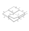
まず、図4又は図5に示すように、第1拘束部16を折り曲げ部16cで直角に折り曲げる。このとき、第1形成部16aに対し、第2形成部16bが直交する状態に賦形されるとともに、第2形成部16bと繋がった第3形成部18bも第2拘束部17に対し直交する状態に賦形される。
まず、図4又は図5に示すように、第1拘束部16を折り曲げ部16cで直角に折り曲げる。このとき、第1形成部16aに対し、第2形成部16bが直交する状態に賦形されるとともに、第2形成部16bと繋がった第3形成部18bも第2拘束部17に対し直交する状態に賦形される。
次に、図6又は図7に示すように、折り曲げ部19cから第3形成部18bを折り曲げ、第2形成部16bに対し第3形成部18bが直交する状態に賦形する。
次に、図8に示すように、折り曲げ部19aから第2拘束部17を折り曲げ、第1形成部16aに対し第3形成部17aが直交するように賦形する。このとき、第3形成部17aと繋がった第2形成部17bも第1形成部16aに対し直交する状態に賦形される。
次に、図8に示すように、折り曲げ部19aから第2拘束部17を折り曲げ、第1形成部16aに対し第3形成部17aが直交するように賦形する。このとき、第3形成部17aと繋がった第2形成部17bも第1形成部16aに対し直交する状態に賦形される。
次に、図9に示すように、折り曲げ部17cから第2拘束部17を折り曲げ、第3形成部17aに対し第2形成部17bが直交するように賦形する。
すると、図10に示すように、第1形成部16aによって第1構造部41が形成されるとともに、第2形成部16bと、第2拘束部17の第2形成部17bとが積層されて第2構造部42が形成される。
すると、図10に示すように、第1形成部16aによって第1構造部41が形成されるとともに、第2形成部16bと、第2拘束部17の第2形成部17bとが積層されて第2構造部42が形成される。
また、図11に示すように、第2拘束部17の第3形成部17aと、第3拘束部18の第3形成部18aと第3形成部18bが積層されて第3構造部43が形成される。
次に、繊維構造体11の作用を記載する。
次に、繊維構造体11の作用を記載する。
図1に示すように、繊維構造体11において、第1構造部41は、第1形成部16aそのもので形成されており、第1緯糸層21、第1経糸層31、第2緯糸層22、第3緯糸層23、第2経糸層32、第4緯糸層24によって形成されている。したがって、第1構造部41は6つの繊維層を有する。
第2構造部42は、第1拘束部16の第2形成部16bと第2拘束部17の第2形成部17bによって形成されている。よって、第2構造部42は、第2形成部16bの第1緯糸層21、第1経糸層31、第2緯糸層22、第3緯糸層23、第2経糸層32、及び第4緯糸層24と、第2形成部17bの第1緯糸層21、第1経糸層31、及び第2緯糸層22と、によって形成されている。したがって、第2構造部42は9つの繊維層を有する。
図11に示すように、第3構造部43は、第2拘束部17の第3形成部17aと、第3拘束部18の第3形成部18a及び第3形成部18bとによって形成されている。よって、第3構造部43は、第3形成部17aの第1緯糸層21、第1経糸層31、及び第2緯糸層22と、第3形成部18aの第3緯糸層23、第2経糸層32、及び第4緯糸層24と、第3形成部18bの第3緯糸層23、第2経糸層32、及び第4緯糸層24と、によって形成されている。したがって、第3構造部43は9つの繊維層を有する。
図1に示すように、繊維構造体11は、第1構造部41と第2構造部42との境界部分である第1コーナ部51を備える。第1コーナ部51は、折り曲げ部16cに沿って屈曲している。第1コーナ部51では、第1方向Y1に沿って延びていた緯糸13が屈曲している。したがって、第1構造部41と第2構造部42とは、緯糸13によって繋がっており、連続性を有する。
繊維構造体11は、第1構造部41と第3構造部43との境界部分である第2コーナ部52を備える。第2コーナ部52は、折り曲げ部19aに沿って屈曲している。第2コーナ部52では、第2方向Y2に沿って延びていた経糸14が屈曲している。したがって、第1構造部41と第3構造部43とは、経糸14によって繋がっており、連続性を有する。
繊維構造体11は、第2構造部42と第3構造部43との境界部分である第3コーナ部53を備える。第3コーナ部53は、折り曲げ部17cに沿って屈曲している。第3コーナ部53では、緯糸13及び経糸14が屈曲している。したがって、第2構造部42と第3構造部43とは、緯糸13及び経糸14によって繋がっており、連続性を有する。
上記実施形態によれば、以下のような効果を得ることができる。
(1)賦形前の繊維構造体11は、多層織物によって構成され、第1拘束部16と、第2拘束部17と、第3拘束部18とを備える。この繊維構造体11は、緯糸13、経糸14、第1の拘束糸15a及び第2の拘束糸15bを用いて織機で製織できる。そして、矩形板形状の繊維構造体11に切込み部18c,19bを形成した後、それら繊維構造体11を賦形することで立体形状の繊維構造体11を形成できる。よって、複数枚の基材を重ねて繊維構造体を製造する必要がなく、繊維構造体11を容易に製造できる。また、特殊な織機を用いて製織する場合と比べると、製造コストを抑えることができる。
(1)賦形前の繊維構造体11は、多層織物によって構成され、第1拘束部16と、第2拘束部17と、第3拘束部18とを備える。この繊維構造体11は、緯糸13、経糸14、第1の拘束糸15a及び第2の拘束糸15bを用いて織機で製織できる。そして、矩形板形状の繊維構造体11に切込み部18c,19bを形成した後、それら繊維構造体11を賦形することで立体形状の繊維構造体11を形成できる。よって、複数枚の基材を重ねて繊維構造体を製造する必要がなく、繊維構造体11を容易に製造できる。また、特殊な織機を用いて製織する場合と比べると、製造コストを抑えることができる。
そして、立体形状の繊維構造体11において、第1コーナ部51は、緯糸13によって連続性が確保され、第2コーナ部52は、経糸14によって連続性が確保されている。また、第3コーナ部53は、緯糸13及び経糸14によって連続性が確保されている。したがって、第1~第3コーナ部51~53で糸が分断されることがなく、第1~第3コーナ部51~53を補強できる。
(2)第1構造部41は6つの繊維層を有するのに対し、第2構造部42及び第3構造部43の各々は9つの繊維層を有する。よって、第2構造部42及び第3構造部43の各々の繊維層の数が、第1構造部41の繊維層の数より多くなり、第2構造部42及び第3構造部43を補強できる。
(3)第1拘束部16の第2形成部16bと第3拘束部18の第3形成部18bとに跨って経糸14が延び、第2拘束部17の第3形成部17aと第2形成部17bとに跨って緯糸13が延びている。このため、第2構造部42及び第3構造部43を形成すると、緯糸13及び経糸14が第3コーナ部53を跨ぐ状態になり、2種類の糸で第3コーナ部53を補強できる。
(4)賦形する前の繊維構造体11において、第1~第3拘束部16~18は、第1の拘束糸15a及び第2の拘束糸15bによって積層方向Y3に拘束されている。したがって、繊維構造体11を賦形するために切込み部18c,19bを有していても繊維構造体11がばらけることがなく、賦形を容易に行うことができる。
(5)第1~第3構造部41~43は、いずれも第1の拘束糸15a及び第2の拘束糸15bによって複数の繊維層が積層方向Y3に拘束されている。この繊維構造体11は織機によって製織できる。したがって、例えば、繊維層を1枚ずつ製職した後、それら繊維層を重ねて繊維構造体11を製造する場合と異なり、複数の繊維層を拘束した繊維構造体11を簡単に製造できる。
なお、上記実施形態は以下のように変更してもよい。
○ 図12に示すように、第1形成部16aが6つの繊維層を有する場合、第2形成部16bの繊維層の数を4としてもよい。すなわち、第2形成部16bの繊維層の数を、第1形成部16aより少なくしてもよい。また、第2拘束部17の第3形成部17a及び第2形成部17bの各々の繊維層の数を2とし、第3拘束部18の第3形成部18a及び第3形成部18bの各々の繊維層の数を2とする。そして、第1構造部41を第1形成部16aそのもので形成し、第2構造部42を第2形成部16bと第2形成部17bとで形成するとともに、第3構造部43を第2拘束部17の第3形成部17aと第3拘束部18の第3形成部18a及び第3形成部18bとで形成する。
○ 図12に示すように、第1形成部16aが6つの繊維層を有する場合、第2形成部16bの繊維層の数を4としてもよい。すなわち、第2形成部16bの繊維層の数を、第1形成部16aより少なくしてもよい。また、第2拘束部17の第3形成部17a及び第2形成部17bの各々の繊維層の数を2とし、第3拘束部18の第3形成部18a及び第3形成部18bの各々の繊維層の数を2とする。そして、第1構造部41を第1形成部16aそのもので形成し、第2構造部42を第2形成部16bと第2形成部17bとで形成するとともに、第3構造部43を第2拘束部17の第3形成部17aと第3拘束部18の第3形成部18a及び第3形成部18bとで形成する。
このように構成すると、第1構造部41、第2構造部42及び第3構造部43は、それぞれ繊維層を6つずつ有するので、第1~第3構造部41~43の強度を互いに同じにできる。
また、繊維層の数を適宜変更することにより、第1~第3構造部41~43の強度を変更することができる。
○ 第2拘束部17を第3形成部17aだけとし、第3コーナ部53において第2構造部42と第3構造部43とに跨る糸を、第2形成部16bと第3形成部18bとに跨る経糸14だけとしてもよい。又は、第3拘束部18を第3形成部18aだけとし、第3コーナ部53において第2構造部42と第3構造部43とに跨る糸を、第3形成部17aと第2形成部17bとに跨る緯糸13だけとしてもよい。
○ 第2拘束部17を第3形成部17aだけとし、第3コーナ部53において第2構造部42と第3構造部43とに跨る糸を、第2形成部16bと第3形成部18bとに跨る経糸14だけとしてもよい。又は、第3拘束部18を第3形成部18aだけとし、第3コーナ部53において第2構造部42と第3構造部43とに跨る糸を、第3形成部17aと第2形成部17bとに跨る緯糸13だけとしてもよい。
○ 平板形状の繊維構造体11の四つの外縁部には、その他の構造部を形成する形成部が繋がっていてもよい。
○ 繊維構造体11において、繊維層は、平織り、繻子織り、又は綾織りで形成されていてもよい。
○ 繊維構造体11において、繊維層は、平織り、繻子織り、又は綾織りで形成されていてもよい。
○ 繊維構造体11において、積層する緯糸層及び経糸層の数は適宜変更してもよい。
○ 繊維構造体11を繊維強化複合材10の強化基材として使用する場合、マトリックス樹脂の種類は、任意に選択することができる。
○ 繊維構造体11を繊維強化複合材10の強化基材として使用する場合、マトリックス樹脂の種類は、任意に選択することができる。
○ 第1構造部41、第2構造部42、及び第3構造部43は矩形状であったが、これに限定されない。例えば、第1構造部41、第2構造部42、及び第3構造部43は台形またはや円形等の任意の形状であってもよい。
Claims (5)
- 第1構造部を形成する第1形成部と、
前記第1構造部と交差する第2構造部を形成する、互いに積層される複数の第2形成部と、
前記第1構造部及び前記第2構造部と交差する第3構造部を形成する、互いに積層される複数の第3形成部と、
前記第1構造部と前記第2構造部との境界部分である第1コーナ部と、
前記第1構造部と前記第3構造部との境界部分である第2コーナ部と、
前記第2構造部と前記第3構造部との境界部分である第3コーナ部と、
を備え、
前記第1形成部、前記複数の第2形成部、及び前記複数の第3形成部の各々は、互いに積層される複数の繊維層と、前記複数の繊維層を積層方向に拘束する拘束糸と、を有する多層織物によって構成され、前記複数の繊維層は、互いに平行な複数の第1の糸により形成される繊維層と、前記複数の第1の糸と直交する方向に延びる、互いに平行な第2の糸により形成される繊維層とを含み、
前記第1構造部と前記第2構造部とに跨る前記第1の糸が前記第1コーナ部で屈曲し、
前記第1構造部と前記第3構造部とに跨る前記第2の糸が前記第2コーナ部で屈曲し、
前記第2構造部と前記第3構造部とに跨る、前記第1の糸及び前記第2の糸のうち少なくとも一方が前記第3コーナ部で屈曲している、繊維構造体。 - 前記複数の第2形成部は、前記第1形成部に繋がった1つ目の第2形成部と、前記1つ目の第2形成部に積層される2つ目の第2形成部と、を含み、
前記複数の第3形成部は、前記第1形成部に繋がった1つ目の第3形成部と、前記1つ目の第3形成部に積層される2つ目の第3形成部と、を含み、
前記第1コーナ部において前記第1形成部と前記1つ目の第2形成部とが前記第1の糸によって繋がるとともに、前記第3コーナ部において前記1つ目の第2形成部と前記2つ目の第3形成部とが前記第2の糸によって繋がっており、
前記第2コーナ部において前記第1形成部と前記1つ目の第3形成部とが前記第2の糸によって繋がるとともに、前記第3コーナ部において前記1つ目の第3形成部と前記2つ目の第2形成部とが前記第1の糸によって繋がっている、請求項1に記載の繊維構造体。 - 前記1つ目の第2形成部及び前記1つ目の第3形成部の各々は、前記第1形成部が有する繊維層の数と同じ数の繊維層を有する、請求項2に記載の繊維構造体。
- 前記1つ目の第2形成部が有する繊維層の数は、前記第1形成部が有する繊維層の数より少なく、かつ前記2つ目の第3形成部が有する繊維層の数は、前記第1形成部が有する繊維層の数よりも少なく、
前記1つ目の第3形成部が有する繊維層の数は、前記第1形成部が有する繊維層の数より少なく、かつ前記2つ目の第2形成部が有する繊維層の数は、前記第1形成部が有する繊維層の数より少なく、
前記第2構造部及び前記第3構造部の各々が有する繊維層の数は、前記第1構造部が有する繊維層の数と同じである、請求項2に記載の繊維構造体。 - 請求項1~請求項4のうちいずれか一項に記載の繊維構造体と、
前記繊維構造体に含浸されたマトリックス樹脂と、
を含む、繊維強化複合材。
Priority Applications (3)
| Application Number | Priority Date | Filing Date | Title |
|---|---|---|---|
| EP18837177.7A EP3660192A4 (en) | 2017-07-24 | 2018-06-28 | FIBER STRUCTURE AND FIBER REINFORCED COMPOSITE MATERIAL |
| CA3070551A CA3070551A1 (en) | 2017-07-24 | 2018-06-28 | Fiber structure and fiber reinforced composite material |
| US16/632,077 US20200216987A1 (en) | 2017-07-24 | 2018-06-28 | Fiber structure and fiber reinforced composite material |
Applications Claiming Priority (2)
| Application Number | Priority Date | Filing Date | Title |
|---|---|---|---|
| JP2017142969A JP6766770B2 (ja) | 2017-07-24 | 2017-07-24 | 繊維構造体及び繊維強化複合材 |
| JP2017-142969 | 2017-07-24 |
Publications (1)
| Publication Number | Publication Date |
|---|---|
| WO2019021738A1 true WO2019021738A1 (ja) | 2019-01-31 |
Family
ID=65040077
Family Applications (1)
| Application Number | Title | Priority Date | Filing Date |
|---|---|---|---|
| PCT/JP2018/024575 Ceased WO2019021738A1 (ja) | 2017-07-24 | 2018-06-28 | 繊維構造体及び繊維強化複合材 |
Country Status (5)
| Country | Link |
|---|---|
| US (1) | US20200216987A1 (ja) |
| EP (1) | EP3660192A4 (ja) |
| JP (1) | JP6766770B2 (ja) |
| CA (1) | CA3070551A1 (ja) |
| WO (1) | WO2019021738A1 (ja) |
Cited By (3)
| Publication number | Priority date | Publication date | Assignee | Title |
|---|---|---|---|---|
| US11034620B2 (en) | 2016-12-20 | 2021-06-15 | Lotte Chemical Corporation | Composition for artificial marble |
| US11505674B2 (en) | 2017-11-08 | 2022-11-22 | Lotte Chemical Corporation | Thermoplastic resin composition and molded article produced from same |
| US12084569B2 (en) | 2018-11-30 | 2024-09-10 | Lotte Chemical Corporation | Thermoplastic resin composition and molded article formed therefrom |
Families Citing this family (1)
| Publication number | Priority date | Publication date | Assignee | Title |
|---|---|---|---|---|
| TR2021011917A1 (tr) * | 2021-07-28 | 2023-02-21 | Veritas Tekstil Konfeksiyon Pazarlama Sanayi Ve Ticaret Anonim Sirketi | 8 katli kumaş çözgü hareketi̇ |
Citations (5)
| Publication number | Priority date | Publication date | Assignee | Title |
|---|---|---|---|---|
| JPS6456514A (en) * | 1987-08-28 | 1989-03-03 | Asahi Fibreglass Co | Manufacture of fiber-reinforced resin body |
| JPH06184906A (ja) * | 1992-12-16 | 1994-07-05 | Shikishima Boseki Kk | 繊維構造体及びその製造方法 |
| JPH09137336A (ja) | 1995-11-13 | 1997-05-27 | Toyota Autom Loom Works Ltd | 三次元繊維構造体及びその製造方法 |
| JPH09506676A (ja) * | 1993-10-25 | 1997-06-30 | ノース・カロライナ・ステイト・ユニバーシティ | 立体布地と製造方法 |
| JP2011167936A (ja) | 2010-02-18 | 2011-09-01 | Mitsubishi Electric Corp | 強化繊維成形体及びその製造方法 |
Family Cites Families (2)
| Publication number | Priority date | Publication date | Assignee | Title |
|---|---|---|---|---|
| US7713893B2 (en) * | 2004-12-08 | 2010-05-11 | Albany Engineered Composites, Inc. | Three-dimensional woven integrally stiffened panel |
| US7413999B2 (en) * | 2005-11-03 | 2008-08-19 | Albany Engineered Composites, Inc. | Corner fitting using fiber transfer |
-
2017
- 2017-07-24 JP JP2017142969A patent/JP6766770B2/ja not_active Expired - Fee Related
-
2018
- 2018-06-28 EP EP18837177.7A patent/EP3660192A4/en not_active Withdrawn
- 2018-06-28 CA CA3070551A patent/CA3070551A1/en not_active Abandoned
- 2018-06-28 US US16/632,077 patent/US20200216987A1/en not_active Abandoned
- 2018-06-28 WO PCT/JP2018/024575 patent/WO2019021738A1/ja not_active Ceased
Patent Citations (5)
| Publication number | Priority date | Publication date | Assignee | Title |
|---|---|---|---|---|
| JPS6456514A (en) * | 1987-08-28 | 1989-03-03 | Asahi Fibreglass Co | Manufacture of fiber-reinforced resin body |
| JPH06184906A (ja) * | 1992-12-16 | 1994-07-05 | Shikishima Boseki Kk | 繊維構造体及びその製造方法 |
| JPH09506676A (ja) * | 1993-10-25 | 1997-06-30 | ノース・カロライナ・ステイト・ユニバーシティ | 立体布地と製造方法 |
| JPH09137336A (ja) | 1995-11-13 | 1997-05-27 | Toyota Autom Loom Works Ltd | 三次元繊維構造体及びその製造方法 |
| JP2011167936A (ja) | 2010-02-18 | 2011-09-01 | Mitsubishi Electric Corp | 強化繊維成形体及びその製造方法 |
Non-Patent Citations (1)
| Title |
|---|
| See also references of EP3660192A4 |
Cited By (3)
| Publication number | Priority date | Publication date | Assignee | Title |
|---|---|---|---|---|
| US11034620B2 (en) | 2016-12-20 | 2021-06-15 | Lotte Chemical Corporation | Composition for artificial marble |
| US11505674B2 (en) | 2017-11-08 | 2022-11-22 | Lotte Chemical Corporation | Thermoplastic resin composition and molded article produced from same |
| US12084569B2 (en) | 2018-11-30 | 2024-09-10 | Lotte Chemical Corporation | Thermoplastic resin composition and molded article formed therefrom |
Also Published As
| Publication number | Publication date |
|---|---|
| EP3660192A1 (en) | 2020-06-03 |
| US20200216987A1 (en) | 2020-07-09 |
| CA3070551A1 (en) | 2019-01-31 |
| JP6766770B2 (ja) | 2020-10-14 |
| EP3660192A4 (en) | 2020-07-15 |
| JP2019023367A (ja) | 2019-02-14 |
Similar Documents
| Publication | Publication Date | Title |
|---|---|---|
| CA2709483C (en) | Method for weaving substrates with integral sidewalls | |
| CN101939472B (zh) | 织造具有交叉壁的封闭结构的方法及其织造的预成型件 | |
| JP6537014B2 (ja) | 指針および時計 | |
| US9365957B2 (en) | Ultralight flat-weave fabric comprising two weft directions | |
| JP6766770B2 (ja) | 繊維構造体及び繊維強化複合材 | |
| US20170190138A1 (en) | Preform with Integrated Gap Fillers | |
| JP5900624B2 (ja) | 三次元繊維強化複合材 | |
| JP5874802B1 (ja) | 繊維構造体及び繊維強化複合材 | |
| JP6524880B2 (ja) | 多層織物 | |
| CN107923082B (zh) | 纤维结构体和纤维增强复合材料 | |
| JP2019094578A (ja) | 繊維構造体及び繊維強化複合材 | |
| WO2015079854A1 (ja) | 繊維強化複合材料 | |
| JP7287162B2 (ja) | 繊維構造体及び繊維強化複合材 | |
| JP2021025164A (ja) | 繊維構造体及び繊維強化複合材 | |
| JP2012096475A (ja) | 強化繊維基材、強化繊維複合材のプリフォームおよび強化繊維複合材 | |
| JP6528651B2 (ja) | 繊維構造体 | |
| JP5644755B2 (ja) | 織物基材及び繊維強化複合材料 | |
| WO2012014613A1 (ja) | 繊維基材及び繊維強化複合材料 | |
| WO2020218040A1 (ja) | 構造材 | |
| WO2014030633A1 (ja) | 三次元繊維強化複合材 | |
| WO2018179877A1 (ja) | 繊維構造体及び繊維強化複合材 | |
| JP2017025216A (ja) | 繊維強化複合材料 | |
| WO2013035518A1 (ja) | 織物基材及び繊維強化複合材料 | |
| JP2022119368A (ja) | 繊維構造体及び繊維強化複合材 |
Legal Events
| Date | Code | Title | Description |
|---|---|---|---|
| 121 | Ep: the epo has been informed by wipo that ep was designated in this application |
Ref document number: 18837177 Country of ref document: EP Kind code of ref document: A1 |
|
| ENP | Entry into the national phase |
Ref document number: 3070551 Country of ref document: CA |
|
| NENP | Non-entry into the national phase |
Ref country code: DE |
|
| ENP | Entry into the national phase |
Ref document number: 2018837177 Country of ref document: EP Effective date: 20200224 |