WO2019021880A1 - 電池パック及びその製造方法 - Google Patents
電池パック及びその製造方法 Download PDFInfo
- Publication number
- WO2019021880A1 WO2019021880A1 PCT/JP2018/026690 JP2018026690W WO2019021880A1 WO 2019021880 A1 WO2019021880 A1 WO 2019021880A1 JP 2018026690 W JP2018026690 W JP 2018026690W WO 2019021880 A1 WO2019021880 A1 WO 2019021880A1
- Authority
- WO
- WIPO (PCT)
- Prior art keywords
- secondary battery
- battery
- battery pack
- cell
- cylindrical
- Prior art date
- Legal status (The legal status is an assumption and is not a legal conclusion. Google has not performed a legal analysis and makes no representation as to the accuracy of the status listed.)
- Ceased
Links
Images




Classifications
-
- H—ELECTRICITY
- H01—ELECTRIC ELEMENTS
- H01M—PROCESSES OR MEANS, e.g. BATTERIES, FOR THE DIRECT CONVERSION OF CHEMICAL ENERGY INTO ELECTRICAL ENERGY
- H01M10/00—Secondary cells; Manufacture thereof
- H01M10/60—Heating or cooling; Temperature control
- H01M10/64—Heating or cooling; Temperature control characterised by the shape of the cells
- H01M10/643—Cylindrical cells
-
- H—ELECTRICITY
- H01—ELECTRIC ELEMENTS
- H01M—PROCESSES OR MEANS, e.g. BATTERIES, FOR THE DIRECT CONVERSION OF CHEMICAL ENERGY INTO ELECTRICAL ENERGY
- H01M10/00—Secondary cells; Manufacture thereof
- H01M10/60—Heating or cooling; Temperature control
- H01M10/65—Means for temperature control structurally associated with the cells
- H01M10/659—Means for temperature control structurally associated with the cells by heat storage or buffering, e.g. heat capacity or liquid-solid phase changes or transition
-
- H—ELECTRICITY
- H01—ELECTRIC ELEMENTS
- H01M—PROCESSES OR MEANS, e.g. BATTERIES, FOR THE DIRECT CONVERSION OF CHEMICAL ENERGY INTO ELECTRICAL ENERGY
- H01M10/00—Secondary cells; Manufacture thereof
- H01M10/60—Heating or cooling; Temperature control
- H01M10/61—Types of temperature control
- H01M10/613—Cooling or keeping cold
-
- H—ELECTRICITY
- H01—ELECTRIC ELEMENTS
- H01M—PROCESSES OR MEANS, e.g. BATTERIES, FOR THE DIRECT CONVERSION OF CHEMICAL ENERGY INTO ELECTRICAL ENERGY
- H01M10/00—Secondary cells; Manufacture thereof
- H01M10/60—Heating or cooling; Temperature control
- H01M10/65—Means for temperature control structurally associated with the cells
- H01M10/653—Means for temperature control structurally associated with the cells characterised by electrically insulating or thermally conductive materials
-
- H—ELECTRICITY
- H01—ELECTRIC ELEMENTS
- H01M—PROCESSES OR MEANS, e.g. BATTERIES, FOR THE DIRECT CONVERSION OF CHEMICAL ENERGY INTO ELECTRICAL ENERGY
- H01M10/00—Secondary cells; Manufacture thereof
- H01M10/60—Heating or cooling; Temperature control
- H01M10/65—Means for temperature control structurally associated with the cells
- H01M10/655—Solid structures for heat exchange or heat conduction
-
- H—ELECTRICITY
- H01—ELECTRIC ELEMENTS
- H01M—PROCESSES OR MEANS, e.g. BATTERIES, FOR THE DIRECT CONVERSION OF CHEMICAL ENERGY INTO ELECTRICAL ENERGY
- H01M50/00—Constructional details or processes of manufacture of the non-active parts of electrochemical cells other than fuel cells, e.g. hybrid cells
- H01M50/20—Mountings; Secondary casings or frames; Racks, modules or packs; Suspension devices; Shock absorbers; Transport or carrying devices; Holders
- H01M50/204—Racks, modules or packs for multiple batteries or multiple cells
- H01M50/207—Racks, modules or packs for multiple batteries or multiple cells characterised by their shape
- H01M50/213—Racks, modules or packs for multiple batteries or multiple cells characterised by their shape adapted for cells having curved cross-section, e.g. round or elliptic
-
- H—ELECTRICITY
- H01—ELECTRIC ELEMENTS
- H01M—PROCESSES OR MEANS, e.g. BATTERIES, FOR THE DIRECT CONVERSION OF CHEMICAL ENERGY INTO ELECTRICAL ENERGY
- H01M50/00—Constructional details or processes of manufacture of the non-active parts of electrochemical cells other than fuel cells, e.g. hybrid cells
- H01M50/20—Mountings; Secondary casings or frames; Racks, modules or packs; Suspension devices; Shock absorbers; Transport or carrying devices; Holders
- H01M50/233—Mountings; Secondary casings or frames; Racks, modules or packs; Suspension devices; Shock absorbers; Transport or carrying devices; Holders characterised by physical properties of casings or racks, e.g. dimensions
- H01M50/24—Mountings; Secondary casings or frames; Racks, modules or packs; Suspension devices; Shock absorbers; Transport or carrying devices; Holders characterised by physical properties of casings or racks, e.g. dimensions adapted for protecting batteries from their environment, e.g. from corrosion
-
- H—ELECTRICITY
- H01—ELECTRIC ELEMENTS
- H01M—PROCESSES OR MEANS, e.g. BATTERIES, FOR THE DIRECT CONVERSION OF CHEMICAL ENERGY INTO ELECTRICAL ENERGY
- H01M50/00—Constructional details or processes of manufacture of the non-active parts of electrochemical cells other than fuel cells, e.g. hybrid cells
- H01M50/20—Mountings; Secondary casings or frames; Racks, modules or packs; Suspension devices; Shock absorbers; Transport or carrying devices; Holders
- H01M50/289—Mountings; Secondary casings or frames; Racks, modules or packs; Suspension devices; Shock absorbers; Transport or carrying devices; Holders characterised by spacing elements or positioning means within frames, racks or packs
- H01M50/291—Mountings; Secondary casings or frames; Racks, modules or packs; Suspension devices; Shock absorbers; Transport or carrying devices; Holders characterised by spacing elements or positioning means within frames, racks or packs characterised by their shape
-
- H—ELECTRICITY
- H01—ELECTRIC ELEMENTS
- H01M—PROCESSES OR MEANS, e.g. BATTERIES, FOR THE DIRECT CONVERSION OF CHEMICAL ENERGY INTO ELECTRICAL ENERGY
- H01M50/00—Constructional details or processes of manufacture of the non-active parts of electrochemical cells other than fuel cells, e.g. hybrid cells
- H01M50/20—Mountings; Secondary casings or frames; Racks, modules or packs; Suspension devices; Shock absorbers; Transport or carrying devices; Holders
- H01M50/289—Mountings; Secondary casings or frames; Racks, modules or packs; Suspension devices; Shock absorbers; Transport or carrying devices; Holders characterised by spacing elements or positioning means within frames, racks or packs
- H01M50/293—Mountings; Secondary casings or frames; Racks, modules or packs; Suspension devices; Shock absorbers; Transport or carrying devices; Holders characterised by spacing elements or positioning means within frames, racks or packs characterised by the material
-
- H—ELECTRICITY
- H01—ELECTRIC ELEMENTS
- H01M—PROCESSES OR MEANS, e.g. BATTERIES, FOR THE DIRECT CONVERSION OF CHEMICAL ENERGY INTO ELECTRICAL ENERGY
- H01M10/00—Secondary cells; Manufacture thereof
- H01M10/60—Heating or cooling; Temperature control
- H01M10/62—Heating or cooling; Temperature control specially adapted for specific applications
- H01M10/623—Portable devices, e.g. mobile telephones, cameras or pacemakers
- H01M10/6235—Power tools
-
- H—ELECTRICITY
- H01—ELECTRIC ELEMENTS
- H01M—PROCESSES OR MEANS, e.g. BATTERIES, FOR THE DIRECT CONVERSION OF CHEMICAL ENERGY INTO ELECTRICAL ENERGY
- H01M10/00—Secondary cells; Manufacture thereof
- H01M10/60—Heating or cooling; Temperature control
- H01M10/62—Heating or cooling; Temperature control specially adapted for specific applications
- H01M10/625—Vehicles
-
- H—ELECTRICITY
- H01—ELECTRIC ELEMENTS
- H01M—PROCESSES OR MEANS, e.g. BATTERIES, FOR THE DIRECT CONVERSION OF CHEMICAL ENERGY INTO ELECTRICAL ENERGY
- H01M10/00—Secondary cells; Manufacture thereof
- H01M10/60—Heating or cooling; Temperature control
- H01M10/62—Heating or cooling; Temperature control specially adapted for specific applications
- H01M10/627—Stationary installations, e.g. power plant buffering or backup power supplies
-
- Y—GENERAL TAGGING OF NEW TECHNOLOGICAL DEVELOPMENTS; GENERAL TAGGING OF CROSS-SECTIONAL TECHNOLOGIES SPANNING OVER SEVERAL SECTIONS OF THE IPC; TECHNICAL SUBJECTS COVERED BY FORMER USPC CROSS-REFERENCE ART COLLECTIONS [XRACs] AND DIGESTS
- Y02—TECHNOLOGIES OR APPLICATIONS FOR MITIGATION OR ADAPTATION AGAINST CLIMATE CHANGE
- Y02E—REDUCTION OF GREENHOUSE GAS [GHG] EMISSIONS, RELATED TO ENERGY GENERATION, TRANSMISSION OR DISTRIBUTION
- Y02E60/00—Enabling technologies; Technologies with a potential or indirect contribution to GHG emissions mitigation
- Y02E60/10—Energy storage using batteries
Definitions
- the present invention relates to a battery pack and a method of manufacturing the same.
- the battery pack is widely used as a power source for an electric power tool, an electric assist bicycle, an electric motorcycle, a hybrid electric car, an electric car and the like, and further for storage of electricity in homes and stores.
- a battery pack can be charged and discharged by connecting a plurality of rechargeable secondary battery cells in series or in parallel.
- a battery assembly 80 in which a plurality of battery cells 81 are housed in a battery holder 82 is housed in a waterproof container 83, and this waterproof container 83 is housed in an outer case 84 as a battery core pack.
- the battery holder 82 makes the plurality of battery cells 81 parallel to each other, arranges the electrode terminals provided at both ends of each battery cell 81 on the same surface, and at both side surfaces of the battery holder 82, The electrode terminals are connected by a lead plate 85.
- potting resin is filled in a state where the battery assembly 80 is housed in a bag-like waterproof container 83.
- the potting resin is made of urethane resin or the like, and the space between the secondary battery cells is filled to achieve soaking, and even if the temperature of one secondary battery cell rises, the other secondary through the potting resin By conducting heat to a battery cell or the like, it is possible to suppress a local temperature rise.
- the present invention has been made in view of such a background, and one of the objects thereof is a battery pack capable of adding a function of suppressing the temperature rise of the secondary battery cell by a simple method, and a method of manufacturing the same To provide.
- a battery assembly formed by storing one or more secondary battery cells in a battery holder holding the secondary battery cells, and the secondary battery cell It is possible to provide a pre-formed flexible heat dissipating molded product that can be melted by the heat generation of the secondary battery cell, which covers the surface, and an outer case that accommodates the battery assembly.
- the said thermal radiation molded object can be comprised with the material which shows the chemical reaction fuse
- the secondary battery cell has a cylindrical appearance
- the heat dissipation molded body is a cylindrical shape of the secondary battery cell. It can be formed into a shape along the curved surface of the side surface. According to the above configuration, the heat dissipating molded body can be disposed along the side surface of the cylindrical secondary battery cell.
- the battery assembly holds the plurality of secondary battery cells in a posture adjacent to one another by the battery holder.
- the heat radiation molded body can be disposed so as to straddle the adjacent secondary battery cell.
- a plurality of secondary battery cells can be covered with one heat dissipating molded body to dissipate heat.
- the secondary battery cell has a cylindrical shape in appearance
- the battery holder is an end portion of the secondary battery cell
- the heat dissipating molded product can cover the side surface of the secondary battery cell exposed from the cell holding portion. According to the above configuration, while the secondary battery cell is held by the battery holder, it is possible to cover the partially exposed cylindrical side surface with the heat dissipating molded body to dissipate the heat.
- the surface of the secondary battery cell held by the battery holder by dividing the heat-radiating molded body into a plurality of pieces Each can be configured to coat.
- the secondary battery cell has a cylindrical outer shape, and the battery holder is adjacent to a plurality of secondary battery cells.
- the heat dissipating molded body may be formed in an annular shape covering the side surface of the secondary battery cell positioned around the periphery of the plurality of secondary battery cells held by the battery holder .
- the battery holder includes a molded body pressing portion that presses the heat dissipating molded body against the surface of the secondary battery cell.
- the heat-radiating molded body can be pressed against the surface of the secondary battery cell without using an adhesive to be in a thermally coupled state.
- the said thermal radiation molded object can be comprised with the material containing a urethane resin or a silicone resin.
- the above-mentioned thermal radiation molded object can be constituted by the material containing the filler which carries out endothermic reaction. According to the above configuration, since the heat radiation molded body partially melts the contact portion with the secondary battery cell due to the heat generation of the secondary battery cell, the heat radiation molded body can be closely adhered without using an adhesive or the like. It is possible to easily obtain a thermally coupled state excellent in heat conduction by reducing the gap serving as the heat insulating layer.
- the battery pack further includes a waterproof container for housing the battery assembly, and the battery assembly is housed in the waterproof container. It can be stored in the outer case. With the above configuration, it is possible to waterproof the battery assembly.
- a battery assembly formed by storing a plurality of cylindrical secondary battery cells in a pair of battery holders holding the cylindrical secondary battery cells.
- a method of manufacturing a battery pack comprising: an outer case for housing the battery assembly, wherein the surface of the cylindrical secondary battery cell is covered, wherein the cylindrical secondary battery cell is meltable by heat generation. And a step of preparing a molded heat dissipating molded product having flexibility, and one end of the cylindrical secondary battery cell being a cylindrical cell holding portion of one of the pair of battery holders.
- a step of inserting in the second step a step of covering the side surface of the cylindrical secondary battery cell exposed from the cell holding portion with the heat dissipation molded body, and the other end of the cylindrical secondary battery cell as the pair Of the other battery holders It may include a step of inserting the cell holding part of the tubular.
- FIG. 7A to 7E are exploded perspective views showing manufacturing steps of the battery pack according to the second embodiment. It is an exploded perspective view showing a conventional battery pack.
- each element constituting the present invention may be configured such that a plurality of elements are constituted by the same member and one member is used in common as a plurality of elements, or conversely, the function of one member is realized by a plurality of members It can be shared and realized. (Embodiment 1)
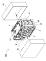
- FIG. 1 is a perspective view showing a battery pack 100 according to Embodiment 1 of the present invention
- FIG. 2 is an exploded perspective view of the battery pack 100 of FIG. 1
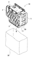
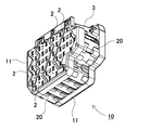
- FIG. 3 is a battery assembly 10 of FIG. 4 is a perspective view of the battery assembly 10 of FIG. 3 viewed from the bottom side
- FIG. 5 is an exploded perspective view of the battery assembly 10 of FIG. 3
- FIG. FIGS. 7A to 7E are exploded perspective views showing manufacturing steps of the battery pack according to the second embodiment, respectively.
- the battery pack 100 shown in FIG. 1 is configured by a box-shaped outer case 40 in an outer shape.
- the exterior case 40 is divided into two as shown in FIG. 2, and a storage space is provided inside.
- the battery assembly 10 is housed in a storage space inside the exterior case 40.
- the outer case 40 is made of a lightweight material having excellent insulation, such as resin.
- the battery assembly 10 exhibits waterproofness by being accommodated in a waterproof container.
- the waterproof container 30 is covered with a waterproof bag 30 as an example of the waterproof container, and has a waterproof property.
- the waterproof bag 30 is made of transparent resin and, for example, polyethylene can be used. In the case where the waterproof function is not provided, the waterproof bag may be omitted.
- the battery assembly 10 has a box shape whose outer shape is partially bounded. As shown in the exploded perspective view of FIG. 5, the battery assembly 10 accommodates a plurality of secondary battery cells 1 in a battery holder 11.
- the battery holder 11 is divided into two on the left and right sides, and held so as to sandwich each of the secondary battery cells 1 from both sides.
- the battery holders 11 are fixed, for example, by screwing, fitting, welding or the like.
- Each battery holder 11 forms a cylindrical cell holding portion 12 for holding an end portion of the secondary battery cell 1 respectively. Further, in a state where the secondary battery cell 1 is set in the battery holder 11, the end face of the secondary battery cell 1 is exposed from the battery holder 11 and welded to the lead plate 2.
- the secondary battery cell 1 is a cylindrical battery having a cylindrical outer can.
- a lithium ion secondary battery, a nickel hydrogen secondary battery, a nickel cadmium secondary battery, etc. can be used.
- a lithium ion secondary battery excellent in energy efficiency per unit volume is preferable.
- a plurality of secondary battery cells 1 are connected in series or in parallel by connecting the electrodes of the end faces with a lead plate 2. In the example of FIG. 5, 35 secondary battery cells 1 are connected by 5 parallels 7 directs. In accordance with this, the shape and the arrangement of the lead plate 2 are determined.
- the lead plate 2 is made of a metal having excellent conductivity.
- the lead plate 2 is connected to the end face of the secondary battery cell 1 by spot welding or the like. Furthermore, the lead plate 2 is connected to the circuit board 3.
- the circuit board 3 is disposed on one surface of the battery holder 11.
- the charge and discharge circuit and the protection circuit of the secondary battery cell 1 are mounted on the circuit board 3. (Thermal radiation molded body 20)
- a heat dissipating molded body 20 is disposed on the surface of the secondary battery cell 1.
- the heat dissipating molded body 20 is a plate-shaped member that has been molded in advance, and is curved according to the shape of the outer can of the secondary battery cell 1. Further, the heat dissipating molded body 20 is formed of a material which has flexibility and is melted by the heat generation of the secondary battery cell 1.
- the temperature tends to be higher in the secondary battery cells located in the periphery than in the middle secondary battery cells.
- the secondary battery cell positioned in the middle even if the temperature rises, it is easily thermally conducted to the secondary battery cells present in the periphery, and as a result, an endothermic effect is exhibited. It is possible to suppress a situation where the temperature of only the next battery cell becomes high.
- the secondary battery cells arranged in the peripheral part since the number of secondary batteries existing in the periphery is small, there is no escape place for heat even if the temperature rises, and as a result, the function to suppress the temperature rise Hard to get.
- the battery assembly is housed in a waterproof bag, and potting resin is injected into the inside and sealed, whereby the potting resin to be injected is brought into close contact with the secondary battery cell in a thermally coupled state and heat is generated. It has been done to improve the conductivity.
- the heat dissipation molded body 20 excellent in thermal conductivity is molded in advance, and the secondary battery cell is assembled at the time of assembly.
- the heat dissipation of the secondary battery cell 1 located around the battery assembly 10 is improved.
- this method it is possible to provide heat dissipation to an arbitrary part by arranging the heat dissipating molded body 20 at a necessary part, as compared to the method of potting the entire battery assembly 10.
- weight reduction is achieved.
- the pre-formed, tangible heat-dissipation molded body 20 can be disposed around the secondary battery cell 1, the manufacturing process can be greatly simplified as compared with the operation of injecting and curing the liquid potting resin.
- the heat dissipating molded body 20 is formed in advance in a shape along the outer shape of the secondary battery cell 1 so as to be easily in close contact with the periphery of the secondary battery cell 1. Furthermore, by using a flexible material, it can be easily deformed according to the actual shape of the secondary battery cell 1 to absorb manufacturing tolerances of the outer can, errors during assembly, etc. Is taken.
- the cylindrical secondary battery cells 1 are held by the battery holder 11 in a state in which the side surfaces are arranged adjacent to each other.
- the battery holder 11 inserts and holds a part of the end face of the cylindrical secondary battery cell 1 in the cell holding portion 12, and exposes the intermediate portion of the outer can from the battery holder 11. Therefore, the heat radiation molded body 20 is disposed at this exposed portion. (Molded body pressing portion 13)
- the heat dissipating molded body 20 is joined to at least a part of the side surface of the secondary battery cell 1 in a thermally coupled state.
- the heat dissipating molded body 20 is bonded to the side surface of the secondary battery cell 1 with an adhesive or an adhesive such as a double-sided tape, or the heat dissipating molded body 20 is physically pressed to the surface of the secondary battery cell 1
- the body pressing portion 13 may be provided on the battery holder 11. In the example of the battery holder 11 shown in the enlarged cross sectional views of FIG. 5 and FIG.
- a rib is formed as a molded body pressing portion 13 in a portion where the outer can of the secondary battery cell 1 is exposed from the battery holder 11
- the heat dissipating molded body 20 is press-fitted between the secondary battery cell 1 and the rib.
- the ribs are formed in a shape that conforms to the outer shape of the heat dissipating molded body 20.
- the rib is substantially parallel to the cell holding portion 12 and is separated from the surface of the secondary battery cell 1 inserted in the cell holding portion 12 by the thickness of the heat dissipating molded body 20 or a slightly narrower interval than this. And protrudes along the extension direction of the cell holding portion 12.
- the ribs do not necessarily have to be provided over the entire surface of the heat radiation molded body 20, and can be partially formed so as to press a part of the heat radiation molded body 20.
- the rib is provided in the position of the trough which made cylindrical secondary battery cell 1 comrades adjoin.
- the rib may be formed into a wall shape or may be a rod shape, or any other configuration capable of holding the heat dissipating molded product can be appropriately used.
- the contact surface of the heat dissipating molded article 20 may be melted and brought into close contact by the heat generation of the secondary battery cell 1.
- the radiation molded body 20 can be brought into close contact with the secondary battery cell 1 without using an adhesive, and a gap is formed between the surface of the outer can and the radiation molded body 20. It is possible to prevent the heat conduction from being hindered by the heat insulation effect of the air layer.
- the heat dissipating molded body 20 uses a resin having high thermal conductivity and heat absorption.
- the urethane resin used by the conventional potting resin can be utilized suitably. By using such a material, heat absorption can be exhibited by the heat capacity of the heat radiation molded body itself.
- the urethane resin material containing the filler component which carries out endothermic reaction in a high temperature range can be used suitably.
- the filler component that reacts endothermicly in the high temperature region exhibits a further heat radiation suppression effect.
- the heat dissipating molded body 20 is disposed so as to straddle the adjacent secondary battery cells 1.
- the adjacent secondary battery cells can be thermally coupled, and even if one secondary battery cell generates heat, another secondary battery cell can be configured to absorb part of the generated heat. That is, the heat conductivity of some secondary battery cells is absorbed by the surrounding secondary battery cells by increasing the thermal conductivity instead of thermally insulating between adjacent secondary battery cells. It becomes possible to suppress runaway.
- each secondary battery cell is not covered with the heat dissipating molded body, but the exposed surface of the secondary battery cells positioned on the outer periphery in the state where the secondary battery cells 1 are stacked is a heat dissipating molded body It has composition covered by 20.
- the thermal conductivity of the secondary battery cells located on the outer periphery is reduced by the amount that the secondary battery cells are not adjacent to the periphery, only the region where the secondary battery cells are not adjacent is covered with the heat dissipation molded body 20 By enhancing the thermal conductivity, the same thermal conductivity as that of the secondary battery cell positioned in the middle of the battery assembly 10 can be exhibited.
- the present invention is not limited to the configuration in which only the region exposed from the battery stack among the secondary battery cells constituting the battery stack is covered with the heat dissipating molded product, for example, secondary battery cells
- the heat dissipating molded body may be interposed between the As a result, the thermal conductivity can be further enhanced also in the middle portion, and the effect of suppressing thermal runaway of some of the secondary battery cells is exhibited.
- the heat dissipating molded body 20 is divided into a plurality of parts as shown in FIG. 5 and arranged around the stacked secondary battery cells 1 respectively. By dividing the heat dissipating molded body 20 in this manner, the work of inserting into the rib of the battery holder 11 can be facilitated.
- the present invention is not limited to this configuration, and the heat dissipating molded product may be integrally formed as in the configuration according to the second embodiment shown in FIG. 7B.
- the heat dissipating molded body 20 ′ is formed in an annular shape so as to cover the side surface of the cylindrical secondary battery cell 1 positioned around the periphery among the plurality of cylindrical secondary battery cells 1 held by the battery holder. With this configuration, the posture of the heat-radiating molded body 20 'becomes clear, and an advantage can be obtained that errors in assembly such as misplacement of parts and errors in direction can be reduced. (Method of manufacturing battery pack)
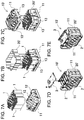
- FIGS. 7A to 7E a method of assembling a battery assembly 10 'according to the second embodiment will be described based on FIGS. 7A to 7E.
- FIG. 7A one side of the divided battery holder 11 is arrange
- FIG. 7B in a state where the secondary battery cell 1 is erected from one of the battery holders 11, the heat radiation molded body 20 'prepared in advance is disposed.
- the heat dissipating molded body 20 ′ covers an area of the side surface of the secondary battery cell 1 which is not covered by the cell holding portion 12 of the battery holder 11.
- the heat dissipating molded body 20 ′ is press-fitted and fixed in the gap between the rib, which is one form of the molded body pressing portion 13, and the secondary battery cell 1.
- the other battery holder 11 covers the upper surface side of the secondary battery cell 1 in the upright posture.
- the edge on the upper surface side of the secondary battery cell 1 is inserted into the cell holding portion 12 of the other battery cell, the rib of the other battery holder 11 is in close contact with the surface of the secondary battery cell 1 Care is taken to press the heat dissipating molded body 20 ′.
- the battery holders 11 are fixed by screwing. Further, the lead plate 2 disposed on the side surface of the battery holder 11 and the end surface of the secondary battery cell 1 are fixed by spot welding or the like.
- the battery cell assembly obtained in this manner is placed in a waterproof bag 30 and sealed, and further, as shown in FIG.
- the battery pack 100 is obtained.
- the heat conductivity between the secondary battery cells is improved by the heat dissipating molded body, so as to achieve thermal uniformity, and even if the temperature of one secondary battery cell rises, the other secondary battery via the heat dissipating molded body By conducting heat to a cell or the like, it is possible to suppress a local temperature rise.
- the heat radiation molded body was formed into a waveform in which the shape in which it was curved along the side surface of the cylindrical outer can is repeated.
- the shape of the secondary battery cell is not limited to a cylindrical shape, and a square battery, a laminate battery, etc. can be used.
- the shape of the heat dissipation molded body is also the secondary battery cell. It is designed in a shape that can be easily attached to the surface according to the shape.
- the container for injecting potting resin for example, a bag
- the container for injecting potting resin can be made unnecessary.
- the battery assembly 10 is housed in the waterproof bag 30 in order to exhibit waterproofness, but this waterproof bag is not for potting resin injection, so for example, when the waterproof function is unnecessary or
- the waterproof bag can be omitted when the waterproof function can be realized by means other than the waterproof bag (for example, by sealing a gap which is an intrusion path of water).
- the battery pack can be suitably used as a power source for an electric power tool, an electric power assisted bicycle, an electric motorbike, a hybrid electric car, an electric car or the like .
Landscapes
- Chemical & Material Sciences (AREA)
- Chemical Kinetics & Catalysis (AREA)
- Electrochemistry (AREA)
- General Chemical & Material Sciences (AREA)
- Engineering & Computer Science (AREA)
- Manufacturing & Machinery (AREA)
- Battery Mounting, Suspending (AREA)
- Secondary Cells (AREA)
- Sealing Battery Cases Or Jackets (AREA)
Abstract
簡便な方法で二次電池セルの温度上昇を抑制する機能を付加する。 一以上の二次電池セル(1)を、該二次電池セル(1)を保持する電池ホルダ(11)に収納してなる電池集合体(10)と、二次電池セル(1)の表面を被覆する、該二次電池セル(1)の発熱により溶融可能な、プレ成型された可撓性を有する放熱成形体(20)と、電池集合体(10)を収納する外装ケースとを備える。上記構成により、従来のように電池集合体の全体をポッティングするのに比べ、必要な部位に放熱成形体(20)を設けることで任意の部位に放熱性を持たせることが可能となり、放熱成形体(20)の量を低減でき、軽量化が図られると共に、製造工程も簡略化できる。
Description
本発明は、電池パック及びその製造方法に関する。
電池パックは、電動工具、電動アシスト自転車、電動バイク、ハイブリッド電気自動車、電気自動車などの電源として、さらには家庭や店舗などでの蓄電用として幅広く用いられている。このような電池パックは、充電可能な二次電池セルを複数、直列や並列に接続して充放電可能としている。例えば図8に示すように、複数の電池セル81を電池ホルダ82に収納してなる電池集合体80を、防水容器83に収納し、この防水容器83を電池のコアパックとして外装ケース84に収納している。電池ホルダ82は、複数の電池セル81を互いに平行な姿勢とし、かつ各電池セル81の両端に設けられた電極端子を同一面に配置すると共に、電池ホルダ82の両側面において、電池セル81の電極端子をリード板85で接続している。
このような電池パックにおいても、近年の高出力化の要求に伴い、二次電池セルの容量や使用数が増大しており、これにより二次電池セルの一部が熱暴走した際の安全対策も求められている。従来の電池パックでは、袋状の防水容器83内に電池集合体80を収納した状態で、ポッティング樹脂を充填している。ポッティング樹脂をウレタン樹脂等として、二次電池セル間の隙間を充填することにより、均熱化を図り、一の二次電池セルの温度が上昇しても、ポッティング樹脂を介して他の二次電池セル等に熱伝導することにより、局部的な温度上昇を抑制することが可能となる。
しかしながら、この方法では防水容器内にポッティング樹脂を充填することから、多量のポッティング樹脂が必要となり、電池パック全体の重量が増大するという問題があった。また電池パックの製造工程において液体状のポッティング樹脂を防水容器に充填し、硬化させる作業が必要となり、時間がかかる上、作業性の面でも好ましくなく、製造のタクトタイム、製造コスト等の点で不利となっていた。
本発明は、このような背景に鑑みてなされたものであり、その目的の一は、簡便な方法で二次電池セルの温度上昇を抑制する機能を付加できるようにした電池パック及びその製造方法を提供することにある。
本発明の第1の形態に係る電池パックによれば、一以上の二次電池セルを、該二次電池セルを保持する電池ホルダに収納してなる電池集合体と、前記二次電池セルの表面を被覆する、該二次電池セルの発熱により溶融可能な、プレ成型された可撓性を有する放熱成形体と、前記電池集合体を収納する外装ケースとを備えることができる。上記構成により、従来のように電池集合体の全体をポッティングするのに比べ、必要な部位に放熱成形体を設けることで任意の部位に放熱性を持たせることが可能となり、放熱成形体の量を低減でき、軽量化が図られると共に、製造工程も簡略化できる。
また第2の形態に係る電池パックによれば、上記構成に加えて、前記放熱成形体を、吸熱反応により溶融する化学反応を示す材質で構成することができる。上記構成により、放熱成形体がこれと接触する二次電池セルの発熱を受けて溶融する際、化学反応を吸熱反応とすることで二次電池セルの冷却効果を発揮させることが可能となる。
さらに第3の形態に係る電池パックによれば、上記何れかの構成に加えて、前記二次電池セルが、外観を円筒形状としており、前記放熱成形体を、前記二次電池セルの円筒形側面の曲面に沿った形状に成形することができる。上記構成により、放熱成形体を円筒形二次電池セルの側面に沿って配置することが可能となる。
さらにまた第4の形態に係る電池パックによれば、上記何れかの構成に加えて、前記電池集合体が、複数の二次電池セルを隣接させた姿勢に、前記電池ホルダで保持しており、前記放熱成形体を、前記隣接する二次電池セルを跨ぐように配置することができる。上記構成により、複数の二次電池セルを一の放熱成形体で被覆して放熱させることができる。
さらにまた第5の形態に係る電池パックによれば、上記何れかの構成に加えて、前記二次電池セルが、外観を円筒形状としており、前記電池ホルダが、前記二次電池セルの端部をそれぞれ保持する円筒形のセル保持部を有する一対の部材で構成されており、前記放熱成形体で、前記セル保持部から露出した前記二次電池セルの側面を被覆することができる。上記構成により、二次電池セルを電池ホルダで保持しつつ、部分的に露出された円筒形側面を放熱成形体で被覆して放熱させることが可能となる。
さらにまた第6の形態に係る電池パックによれば、上記何れかの構成に加えて、前記放熱成形体を、複数に分割して、前記電池ホルダに保持された前記二次電池セルの表面をそれぞれ被覆するよう構成することができる。
さらにまた第7の形態に係る電池パックによれば、上記何れかの構成に加えて、前記二次電池セルが、外観を円筒形状としており、前記電池ホルダが、複数の二次電池セルを隣接する姿勢で保持しており、前記放熱成形体を、前記電池ホルダに保持された複数の前記二次電池セルの内、周囲に位置する二次電池セルの側面を覆う環状に形成することができる。
さらにまた第8の形態に係る電池パックによれば、上記何れかの構成に加えて、前記電池ホルダに、前記放熱成形体を前記二次電池セルの表面に押圧する成形体押圧部を備えることができる。上記構成により、放熱成形体を接着材を使用することなく二次電池セルの表面に押圧して熱結合状態とすることができる。
さらにまた第9の形態に係る電池パックによれば、上記何れかの構成に加えて、前記放熱成形体を、ウレタン樹脂又はシリコーン樹脂を含む材質で構成することができる。
さらにまた第10の形態に係る電池パックによれば、上記何れかの構成に加えて、前記放熱成形体を、吸熱反応するフィラーを含む材質で構成することができる。上記構成により、放熱成形体が、二次電池セルとの接触部分がこの二次電池セルの発熱によって部分的に溶融するため、接着材等を用いることなく密着させることが可能となり、接触界面で断熱層となる隙間を低減して、熱伝導に優れた熱結合状態を容易に得ることが可能となる。
さらにまた第11の形態に係る電池パックによれば、上記何れかの構成に加えて、さらに前記電池集合体を収納する防水容器を備え、前記電池集合体を前記防水容器に収納した状態で、前記外装ケース内に収納することができる。上記構成により、電池集合体の防水を図ることが可能となる。
さらにまた第12の形態に係る電池パックの製造方法によれば、複数の円筒形二次電池セルを、該円筒形二次電池セルを保持する一対の電池ホルダに収納してなる電池集合体と、前記電池集合体を収納する外装ケースとを備える電池パックの製造方法であって、前記円筒形二次電池セルの表面を被覆する、該円筒形二次電池セルの発熱により溶融可能な、プレ成型された可撓性を有する放熱成形体を準備する工程と、前記円筒形二次電池セルの一方の端部を、前記一対の電池ホルダの内、一方の電池ホルダの円筒形のセル保持部に挿入する工程と、前記セル保持部から露出した前記円筒形二次電池セルの側面を、前記放熱成形体で被覆する工程と、前記円筒形二次電池セルの他方の端部を、前記一対の電池ホルダの内、他方の電池ホルダの円筒形のセル保持部に挿入する工程とを含むことができる。これにより、従来のように電池集合体の全体をポッティングするのに比べ、必要な部位に放熱成形体を設けることで任意の部位に放熱性を持たせることが可能となり、放熱成形体の量を低減でき、軽量化が図られると共に、製造工程も簡略化できる。
以下、本発明の実施形態を図面に基づいて説明する。ただし、以下に示す実施形態は、本発明の技術思想を具体化するための例示であって、本発明は以下のものに特定されない。また、本明細書は特許請求の範囲に示される部材を、実施形態の部材に特定するものでは決してない。特に実施形態に記載されている構成部品の寸法、材質、形状、その相対的配置等は特に特定的な記載がない限りは、本発明の範囲をそれのみに限定する趣旨ではなく、単なる説明例にすぎない。なお、各図面が示す部材の大きさや位置関係等は、説明を明確にするため誇張していることがある。さらに以下の説明において、同一の名称、符号については同一若しくは同質の部材を示しており、詳細説明を適宜省略する。さらに、本発明を構成する各要素は、複数の要素を同一の部材で構成して一の部材で複数の要素を兼用する態様としてもよいし、逆に一の部材の機能を複数の部材で分担して実現することもできる。
(実施形態1)
(実施形態1)
実施形態1に係る電池パックを図1~図7Eに示す。これらの図において、図1は本発明の実施形態1に係る電池パック100を示す斜視図、図2は図1の電池パック100の分解斜視図、図3は図2の電池集合体10を示す斜視図、図4は図3の電池集合体10を底面側から見た斜視図、図5は図3の電池集合体10の分解斜視図、図6は放熱成形体を挿入する部位を示す拡大分解斜視図、図7A~図7Eは実施形態2に係る電池パックの製造工程を示す分解斜視図を、それぞれ示している。図1に示す電池パック100は、外形を箱形の外装ケース40で構成している。外装ケース40は、図2に示すように二分割され、内部に収納空間を設けている。外装ケース40内部の収納空間には、電池集合体10が収納される。外装ケース40は、絶縁性に優れた軽量な材質、例えば樹脂製とする。
電池集合体10は、防水容器に収納することで防水性を発揮させる。図3に示す例では、防水容器の一例として防水袋30で覆われており、防水性を持たせている。防水袋30は、透明な樹脂製で、例えばポリエチレンなどが利用できる。なお、防水機能を持たせない場合は、防水袋を省略してもよい。
電池集合体10は、図3、図4に示すように外形を一部が括れた箱形としている。この電池集合体10は、図5の分解斜視図に示すように、複数本の二次電池セル1を電池ホルダ11に収納している。電池ホルダ11は左右に二分割して、各二次電池セル1を両側から挟み込むようにして保持している。電池ホルダ11同士は、例えばねじ止めや嵌合、溶接などによって固定される。各電池ホルダ11は、二次電池セル1の端部をそれぞれ保持する円筒形のセル保持部12を形成している。また電池ホルダ11に二次電池セル1をセットした状態で、二次電池セル1の端面を電池ホルダ11から表出させて、リード板2と溶接するように構成している。
二次電池セル1は、円筒形の外装缶を有する円筒形電池である。例えばリチウムイオン二次電池やニッケル水素二次電池、ニッケルカドミウム二次電池等が利用できる。特に単位体積あたりのエネルギー効率に優れたリチウムイオン二次電池が好ましい。複数の二次電池セル1は、端面の電極をリード板2で接続して、直列や並列に接続される。図5の例では、35本の二次電池セル1を5並7直で接続している。これに応じてリード板2の形状や配置が決定される。
リード板2は導電性に優れた金属で構成される。リード板2はスポット溶接等によって二次電池セル1の端面と接続される。さらにリード板2は回路基板3と接続される。回路基板3は電池ホルダ11の一面に配置される。回路基板3には、二次電池セル1の充放電回路や保護回路が実装される。
(放熱成形体20)
(放熱成形体20)
さらに二次電池セル1の表面には、放熱成形体20が配置されている。放熱成形体20は、予め成形された板状の部材であり、二次電池セル1の外装缶の形状に応じて湾曲されている。また放熱成形体20は、可撓性を有すると共に、二次電池セル1の発熱により溶融する材質で形成される。
二次電池セルを複数、隣接させて用いる電池パックでは、中間の二次電池セルよりも周囲に位置する二次電池セルの方が温度が高くなりやすい傾向にある。それは、中間に位置する二次電池セルの場合は、仮に温度が高くなっても、周囲に存在する二次電池セルに熱伝導され易く、結果として吸熱効果が発揮されるため、一部の二次電池セルのみの温度が高くなる事態を抑制できる。これに対して周囲部に配置された二次電池セルでは、周囲に存在する二次電池の数が少ないことから、温度上昇しても熱の逃げ場が無く、結果として温度上昇を抑制する機能が得られ難い。このため、二次電池セルの発熱を効率的に伝熱する機構が必要となる。そこで従来の電池パックでは、電池集合体を防水袋に収納して、内部にポッティング樹脂を注入して密閉することで、注入されるポッティング樹脂を二次電池セルに熱結合状態に密着して熱伝導性を向上させることが行われてきた。
しかしながら、この構造の電池パックは、注入されるポッティング樹脂を全ての二次電池セルの表面に熱結合するために、内部の隙間を満たすようにポッティング樹脂を大量に充填する必要があることから、注入するポッティング樹脂の量が多くなって、電池パックの重量が増加する。電池パックは小型軽量化が求められており、特にアシスト自転車用の電池パックは、電池パック自体が重くなるとその分だけ駆動力が必要となってアシスト効果が損なわれてしまうことから、軽量化の要求が高い。また大量のポッティング樹脂を使用することで製造コストが高くなる上、製造工程においても、液状のポッティング樹脂の注入工程や、これが硬化されるまでの待ち時間の発生などが生じることから、タクトタイムが長くなって生産性の面でも不利となり、さらに製造コストを押し上げる要因となっていた。
これに対して本実施形態に係る電池パック100では、このようなポッティング樹脂の注入や硬化に代えて、予め熱伝導性に優れた放熱成形体20を成形しておき、組立時に二次電池セル1の周囲を被覆することで、電池集合体10の周囲に位置する二次電池セル1の放熱性を向上させている。この方法であれば、電池集合体10の全体をポッティングする方法に比べ、必要な部位に放熱成形体20を配置することで任意の部位に放熱性を持たせることが可能となる。また放熱成形体20の量を低減できる結果、軽量化が図られる。さらに、プレ成形された有形の放熱成形体20を二次電池セル1の周囲に配置できることから、液状のポッティング樹脂を注入、硬化させる作業と比べて製造工程を大幅に簡略化できる。
放熱成形体20は、二次電池セル1の周囲に密着させやすいよう、二次電池セル1の外形に沿う形状に予め成形される。さらに、可撓性を有する材質とすることで、実際の二次電池セル1の形状に応じて変形させやすくして、外装缶の製造公差や組み付け時の誤差などを吸収して一層の密着性が図られる。図5の例では、円筒形二次電池セル1を側面同士が隣接する姿勢に並べた状態で電池ホルダ11によって保持されている。電池ホルダ11は、円筒形二次電池セル1の端面の一部をセル保持部12に挿入して保持し、外装缶の中間部分を電池ホルダ11から露出させている。よって、この露出部分に放熱成形体20を配置する。
(成形体押圧部13)
(成形体押圧部13)
放熱成形体20は、二次電池セル1の側面の少なくとも一部に、熱結合状態に接合される。放熱成形体20は、接着剤や両面テープ等の接着材で二次電池セル1の側面に貼付する構成とする他、放熱成形体20を物理的に二次電池セル1の表面に押圧する成形体押圧部13を電池ホルダ11に設けてもよい。図5及び図6の拡大断面図に示す電池ホルダ11の例では、成形体押圧部13として、二次電池セル1の外装缶が電池ホルダ11から表出する部位に、リブを形成して、二次電池セル1とリブとの間に放熱成形体20を圧入するように構成している。この構成であれば、組立時に放熱成形体20を容易に二次電池セル1の表面に押圧させることが可能となり、接着材を塗布する必要が無く、組立作業の作業性を高めることが可能となる。
リブは、放熱成形体20の外形に沿う形状に形成される。またリブは、セル保持部12と略平行に、セル保持部12に挿入された二次電池セル1の表面から放熱成形体20の厚さ分、又はこれよりも若干狭い間隔だけ離間させた姿勢でセル保持部12の延長方向に沿って突出されている。これにより、可撓性を有する放熱成形体20をリブと二次電池セル1との間の隙間に圧入して、放熱成形体20を隙間なく二次電池セル1の表面に密着させることができる。
またリブは、放熱成形体20の全面に渡って設ける必要は必ずしもなく、放熱成形体20の一部を押圧するように部分的に形成することができる。図6の例では、円筒形二次電池セル1同士を隣接させた谷間の位置にリブを設けている。これによって、リブを円筒形二次電池セル1の頂部に設けた場合と比べて、リブが外部に突出して電池ホルダが厚くなって大型化する事態を回避できる。なお、リブは壁状に形成する他、ロッド状とするなど、放熱成形体を保持可能な任意の構成が適宜利用できる。
さらに、二次電池セル1の発熱によって放熱成形体20の接触面を溶融させて密着されるようにしてもよい。この方法であれば、接着剤を用いることなく放熱成形体20を二次電池セル1と密着させることが可能となり、外装缶の表面と放熱成形体20との間に隙間が形成されることによって空気層の断熱効果で熱伝導が阻害される事態を回避できる。
放熱成形体20は、熱伝導性及び吸熱性の高い樹脂を用いる。例えば従来のポッティング樹脂で用いられていたウレタン樹脂を好適に利用できる。このような材質を用いることによって、放熱成形体自体の熱容量によって吸熱性を発揮できる。
加えて、発熱反応でなく吸熱反応によって溶融する材質とすることが好ましい。これにより、二次電池セル1の発熱時に、吸熱反応による化学反応でも熱を奪う効果が発揮できる。このような材質としては、高温領域で吸熱反応するフィラー成分を含んだウレタン樹脂材が好適に利用できる。この場合は、高温領域で吸熱反応するフィラー成分により一層の放熱抑制効果が発揮される。
放熱成形体20は、隣接する二次電池セル1を跨ぐように配置されている。これによって隣接する二次電池セルを熱結合状態として、一の二次電池セルが発熱しても、他の二次電池セルで発熱の一部を吸収するように構成できる。すなわち、隣接する二次電池セル同士の間を断熱するのでなく、逆に熱伝導性を高めることで、一部の二次電池セルの発熱を、周囲の二次電池セルで吸収することによって熱暴走を抑制することが可能となる。
なお図5等の例では、各二次電池セルの周囲全体を放熱成形体で覆うのでなく、二次電池セル1を積層した状態で外周に位置する二次電池セルの露出面を放熱成形体20で覆う構成としている。上述の通り、外周に位置する二次電池セルは、周囲に二次電池セルが隣接しない分だけ熱伝導性が低下するため、二次電池セルが隣接しない領域のみを放熱成形体20で覆い、熱伝導性を高めることで、電池集合体10の中間に位置する二次電池セルと同様の熱伝導性を発揮できる。ただ、本発明は電池積層体を構成する二次電池セルの内、電池積層体から表出する領域のみを放熱成形体で被覆する構成に限定せず、例えば中間部分においても二次電池セル同士の間に放熱成形体を介在させてもよい。これによって中間部分においても熱伝導性を一層高めて、一部の二次電池セルの熱暴走を抑制できる効果が発揮される。
また放熱成形体20は、図5に示すように複数のパーツに分割して、積層状態の二次電池セル1の周囲にそれぞれ配置される。このように放熱成形体20を分割することで、電池ホルダ11のリブに挿入する作業を行い易くできる。ただ、本発明はこの構成に限らず、図7Bに示す実施形態2に係る構成のように、放熱成形体を一体に形成してもよい。この放熱成形体20’は、電池ホルダに保持された複数の円筒形二次電池セル1の内、周囲に位置する円筒形二次電池セル1の側面を覆う環状に形成されている。この構成であれば、放熱成形体20’の姿勢が明確となって、パーツの取り違いや方向の正誤といった組立時のミスを低減できる利点が得られる。
(電池パックの製造方法)
(電池パックの製造方法)
ここで、電池パックの製造方法の一部として、実施形態2に係る電池集合体10’の組立方法を図7A~図7Eに基づいて説明する。まず図7Aに示すように、二分割した電池ホルダ11の一方を下側に配置して、二次電池セル1をセル保持部12に各々挿入する。次に図7Bに示すように、二次電池セル1を一方の電池ホルダ11から直立させた状態で、予め用意された放熱成形体20’を配置する。放熱成形体20’は、二次電池セル1の側面の内、電池ホルダ11のセル保持部12で被覆されない領域を被覆する。この例では、成形体押圧部13の一形態であるリブと、二次電池セル1との隙間に、放熱成形体20’を圧入して固定する。
この状態で図7Cに示すように、他方の電池ホルダ11で、直立姿勢の二次電池セル1の上面側を被覆する。このとき、他方の電池セルのセル保持部12に、二次電池セル1の上面側の端縁を挿入する際、他方の電池ホルダ11のリブで、二次電池セル1の表面に密着された放熱成形体20’を押圧するように注意する。そして、電池ホルダ11同士をねじ止めによって固定する。また、電池ホルダ11の側面に配置したリード板2と、二次電池セル1の端面とをスポット溶接等で固定する。次に、電池集合体10’を横向きに倒した姿勢から、図7Dに示すように直立姿勢に立てて、上面に回路基板3を固定し、回路基板3とリード板2とを接続する。このようにして、図7Eに示すように電池セル集合体が得られる。
このようにして得られた電池セル集合体を、図3に示すように防水袋30に入れて密封し、さらに図2に示すように左右から外装ケース40に収納することで、図1に示す電池パック100が得られる。
このようにして、従来のように電池集合体の全体をポッティングするのに比べ、必要な部位に放熱成形体を設けることで任意の部位に放熱性を持たせることが可能となり、放熱成形体の量を低減でき、軽量化が図られると共に、製造工程も簡略化できる。また放熱成形体は、二次電池セルとの接触部分がこの二次電池セルの発熱によって部分的に溶融するため、接着材等を用いることなく密着させることが可能となり、接触界面で断熱層となる隙間を低減して、熱伝導に優れた熱結合状態を容易に得ることが可能となる。さらに放熱成形体によって二次電池セル間の熱伝導性が向上されて均熱化が図られ、一の二次電池セルの温度が上昇しても、放熱成形体を介して他の二次電池セル等に熱伝導することにより、局部的な温度上昇を抑制することが可能となる。
なお以上の例では、二次電池セルに円筒形電池を用いたため、放熱成形体を円筒形の外装缶の側面に沿って湾曲させた形状を繰り返した波形に形成したものを用いた。ただ本発明は、二次電池セルの形状を円筒形に限定せず、角型電池やラミネート電池等を利用することもでき、このような場合は放熱成形体の形状も、二次電池セルの形状に応じて表面に密着しやすい形状に設計される。
またこの構成によれば、ポッティング樹脂を注入するための容器、例えば袋を不要とできる。なお図3の例では、防水性を発揮させるために防水袋30に電池集合体10を収納しているが、この防水袋はポッティング樹脂の注入用ではないため、例えば防水機能が不要な場合や、防水機能を防水袋以外の手段で実現できる場合(例えば水の侵入経路となる隙間をシールする等)には、防水袋を省略できる。
本発明の電池パック及びその製造方法によれば、電動工具、電動アシスト自転車、電動バイク、ハイブリッド電気自動車、電気自動車などの電源、あるいは家庭や店舗などでの蓄電用の電源として、好適に利用できる。
100…電池パック
1…二次電池セル
2…リード板
3…回路基板
10、10’…電池集合体
11…電池ホルダ
12…セル保持部
13…成形体押圧部(リブ)
20、20’…放熱成形体
30…防水袋
40…外装ケース
80…電池集合体
81…電池セル
82…電池ホルダ
83…防水容器
84…外装ケース
85…リード板
1…二次電池セル
2…リード板
3…回路基板
10、10’…電池集合体
11…電池ホルダ
12…セル保持部
13…成形体押圧部(リブ)
20、20’…放熱成形体
30…防水袋
40…外装ケース
80…電池集合体
81…電池セル
82…電池ホルダ
83…防水容器
84…外装ケース
85…リード板
Claims (12)
- 一以上の二次電池セルを、該二次電池セルを保持する電池ホルダに収納してなる電池集合体と、
前記二次電池セルの表面を被覆する、該二次電池セルの発熱により溶融可能な、プレ成型された可撓性を有する放熱成形体と、
前記電池集合体を収納する外装ケースと、
を備える電池パック。 - 請求項1に記載の電池パックであって、
前記放熱成形体が、吸熱反応により溶融する化学反応を示す材質で構成されてなる電池パック。 - 請求項1又は2に記載の電池パックであって、
前記二次電池セルが、外観を円筒形状としており、
前記放熱成形体が、前記二次電池セルの円筒形側面の曲面に沿った形状に成形されてなる電池パック。 - 請求項1~3のいずれか一に記載の電池パックであって、
前記電池集合体が、複数の二次電池セルを隣接させた姿勢に、前記電池ホルダで保持しており、
前記放熱成形体が、前記隣接する二次電池セルを跨ぐように配置されてなる電池パック。 - 請求項1~4のいずれか一に記載の電池パックであって、
前記二次電池セルが、外観を円筒形状としており、
前記電池ホルダが、前記二次電池セルの端部をそれぞれ保持する円筒形のセル保持部を有する一対の部材で構成されており、
前記放熱成形体が、前記セル保持部から露出した前記二次電池セルの側面を被覆してなる電池パック。 - 請求項1~5のいずれか一に記載の電池パックであって、
前記放熱成形体が、複数に分割されて、前記電池ホルダに保持された前記二次電池セルの表面をそれぞれ被覆するよう構成されてなるパック電池。 - 請求項1~5のいずれか一に記載の電池パックであって、
前記二次電池セルが、外観を円筒形状としており、
前記電池ホルダが、複数の前記二次電池セルを隣接する姿勢で保持しており、
前記放熱成形体が、前記電池ホルダに保持された複数の前記二次電池セルの内、周囲に位置する二次電池セルの側面を覆う環状に形成されてなる電池パック。 - 請求項1~7のいずれか一に記載の電池パックであって、
前記電池ホルダが、前記放熱成形体を前記二次電池セルの表面に押圧する成形体押圧部を備えてなる電池パック。 - 請求項1~8のいずれか一に記載の電池パックであって、
前記放熱成形体が、ウレタン樹脂又はシリコーン樹脂を含む材質で構成されてなる電池パック。 - 請求項1~9のいずれか一に記載の電池パックであって、
前記放熱成形体が、吸熱反応するフィラーを含む材質で構成されてなる電池パック。 - 請求項1~10のいずれか一に記載の電池パックであって、さらに
前記電池集合体を収納する防水容器を備え、
前記電池集合体を前記防水容器に収納した状態で、前記外装ケース内に収納してなる電池パック。 - 複数の円筒形二次電池セルを、該円筒形二次電池セルを保持する一対の電池ホルダに収納してなる電池集合体と、前記電池集合体を収納する外装ケースとを備える電池パックの製造方法であって、
前記円筒形二次電池セルの表面を被覆する、該円筒形二次電池セルの発熱により溶融可能な、プレ成型された可撓性を有する放熱成形体を準備する工程と、
前記円筒形二次電池セルの一方の端部を、前記一対の電池ホルダの内、一方の電池ホルダの円筒形のセル保持部に挿入する工程と、
前記セル保持部から露出した前記円筒形二次電池セルの側面を、前記放熱成形体で被覆する工程と、
前記円筒形二次電池セルの他方の端部を、前記一対の電池ホルダの内、他方の電池ホルダの円筒形のセル保持部に挿入する工程と、
を含む電池パックの製造方法。
Priority Applications (4)
| Application Number | Priority Date | Filing Date | Title |
|---|---|---|---|
| CN201880044410.2A CN110832694B (zh) | 2017-07-24 | 2018-07-17 | 电池组以及其制造方法 |
| JP2019532519A JP7068308B2 (ja) | 2017-07-24 | 2018-07-17 | 電池パック及びその製造方法 |
| US16/629,117 US11417923B2 (en) | 2017-07-24 | 2018-07-17 | Battery pack and manufacturing method therefor |
| EP18838503.3A EP3660973B1 (en) | 2017-07-24 | 2018-07-17 | Battery pack and manufacturing method therefor |
Applications Claiming Priority (2)
| Application Number | Priority Date | Filing Date | Title |
|---|---|---|---|
| JP2017-143045 | 2017-07-24 | ||
| JP2017143045 | 2017-07-24 |
Publications (1)
| Publication Number | Publication Date |
|---|---|
| WO2019021880A1 true WO2019021880A1 (ja) | 2019-01-31 |
Family
ID=65040793
Family Applications (1)
| Application Number | Title | Priority Date | Filing Date |
|---|---|---|---|
| PCT/JP2018/026690 Ceased WO2019021880A1 (ja) | 2017-07-24 | 2018-07-17 | 電池パック及びその製造方法 |
Country Status (5)
| Country | Link |
|---|---|
| US (1) | US11417923B2 (ja) |
| EP (1) | EP3660973B1 (ja) |
| JP (1) | JP7068308B2 (ja) |
| CN (1) | CN110832694B (ja) |
| WO (1) | WO2019021880A1 (ja) |
Cited By (5)
| Publication number | Priority date | Publication date | Assignee | Title |
|---|---|---|---|---|
| CN109991268A (zh) * | 2019-04-01 | 2019-07-09 | 清华大学 | 确定电池热失控作用机制的方法 |
| JPWO2019163549A1 (ja) * | 2018-02-22 | 2021-02-25 | 三洋電機株式会社 | 電池パック及びその製造方法 |
| WO2023080551A1 (ko) * | 2021-11-08 | 2023-05-11 | 주식회사 엘지에너지솔루션 | 폿팅 수지의 누액 방지 기능이 구비된 전지 모듈 및 이를 포함하는 전지 팩 |
| US20230361440A1 (en) * | 2019-12-03 | 2023-11-09 | Sanyo Electric Co., Ltd. | Battery pack |
| US12586830B2 (en) | 2020-10-12 | 2026-03-24 | Lg Energy Solution, Ltd. | Battery module, battery pack, and vehicle |
Families Citing this family (8)
| Publication number | Priority date | Publication date | Assignee | Title |
|---|---|---|---|---|
| JP7277596B2 (ja) * | 2019-10-03 | 2023-05-19 | 本田技研工業株式会社 | バッテリモジュール、電動パワーユニット、および作業機 |
| KR102909624B1 (ko) | 2020-11-16 | 2026-01-08 | 주식회사 엘지에너지솔루션 | 가이드 프레임이 구비된 전지 모듈 및 이의 제조방법 |
| KR102908125B1 (ko) * | 2021-01-11 | 2026-01-05 | 주식회사 엘지에너지솔루션 | 배터리 팩 및 이를 포함하는 자동차 |
| EP4351834A4 (en) | 2021-06-09 | 2025-12-31 | Black & Decker Inc | BATTERY BLOCK INSULATION SYSTEM |
| DE102021116350A1 (de) | 2021-06-24 | 2022-12-29 | Bayerische Motoren Werke Aktiengesellschaft | Gehäuseteil und Verfahren zum Verbinden der Speicherzellen eines Energiespeichers |
| DE102022123940A1 (de) * | 2022-09-19 | 2024-03-21 | Bayerische Motoren Werke Aktiengesellschaft | Elektrischer Energiespeicher für ein Kraftfahrzeug sowie Kraftfahrzeug |
| EP4342639A1 (de) * | 2022-09-23 | 2024-03-27 | C. & E. Fein GmbH | Lagervorrichtung für ein akkumulatormodul an einem handwerkzeug |
| KR20250038076A (ko) * | 2023-09-11 | 2025-03-19 | 주식회사 엘지에너지솔루션 | 배터리 팩 |
Citations (7)
| Publication number | Priority date | Publication date | Assignee | Title |
|---|---|---|---|---|
| JPH0992237A (ja) | 1995-09-27 | 1997-04-04 | Sony Corp | 円筒型二次電池及びその組電池 |
| JP2001307784A (ja) * | 2000-04-20 | 2001-11-02 | Japan Storage Battery Co Ltd | 組電池 |
| JP2010062093A (ja) | 2008-09-05 | 2010-03-18 | Panasonic Corp | 電池パック |
| JP2011521403A (ja) * | 2008-04-14 | 2011-07-21 | エイ 123 システムズ,インク. | 自在電圧の重畳収納可能な電池モジュール設計 |
| JP2011253747A (ja) * | 2010-06-03 | 2011-12-15 | Nippon Telegr & Teleph Corp <Ntt> | 蓄電池モジュール |
| JP2013012441A (ja) * | 2011-06-30 | 2013-01-17 | Sanyo Electric Co Ltd | 電源装置及び電源装置を備える車両 |
| JP2016056352A (ja) * | 2014-09-05 | 2016-04-21 | 東洋ゴム工業株式会社 | 熱伝導率可変材料、当該熱伝導率可変材料を用いた熱制御装置、及び当該熱伝導率可変材料を用いた熱制御方法 |
Family Cites Families (28)
| Publication number | Priority date | Publication date | Assignee | Title |
|---|---|---|---|---|
| JP4079572B2 (ja) * | 2000-04-14 | 2008-04-23 | 松下電器産業株式会社 | 電池パック |
| JP4196521B2 (ja) * | 2000-05-19 | 2008-12-17 | 新神戸電機株式会社 | 電気自動車用バッテリ構造及び電池モジュール |
| JP2002184374A (ja) * | 2000-12-12 | 2002-06-28 | Honda Motor Co Ltd | 電池パック |
| JP4274805B2 (ja) * | 2003-01-27 | 2009-06-10 | パナソニック株式会社 | パック電池 |
| JP2005285456A (ja) * | 2004-03-29 | 2005-10-13 | Sanyo Electric Co Ltd | 電源装置 |
| JP2006261009A (ja) * | 2005-03-18 | 2006-09-28 | Toshiba Corp | バッテリーパック |
| JP4958409B2 (ja) * | 2005-06-01 | 2012-06-20 | 三洋電機株式会社 | 組電池 |
| CN201032639Y (zh) * | 2005-10-31 | 2008-03-05 | 布莱克和戴克公司 | 用于无塞绳电动工具的电池组 |
| CN200976359Y (zh) * | 2006-11-30 | 2007-11-14 | 浙江东冠瑞宝科技有限公司 | 电动车锂电池使用安全性能增强装置 |
| DE102008032086A1 (de) * | 2008-07-08 | 2010-01-14 | Valeo Klimasysteme Gmbh | Antriebsbatteriebaugruppe eines Elektro-, Brennstoffzellen- oder Hybridfahrzeugs |
| JP5326480B2 (ja) * | 2008-10-14 | 2013-10-30 | トヨタ自動車株式会社 | 蓄電装置 |
| JP4900534B2 (ja) * | 2009-02-24 | 2012-03-21 | パナソニック株式会社 | 電池モジュールとそれを用いた電池モジュール集合体 |
| KR101057563B1 (ko) * | 2009-07-01 | 2011-08-17 | 삼성에스디아이 주식회사 | 배터리 팩 |
| CN102195010B (zh) * | 2010-03-10 | 2014-03-12 | 三洋电机株式会社 | 具备导板的电池包 |
| JP5663962B2 (ja) * | 2010-05-31 | 2015-02-04 | ソニー株式会社 | 電池ユニット |
| JP2012160260A (ja) * | 2011-01-28 | 2012-08-23 | Nifco Inc | バッテリパック |
| JP6044186B2 (ja) * | 2012-08-30 | 2016-12-14 | ソニー株式会社 | 電池パックおよび電動車両 |
| JP6318372B2 (ja) * | 2014-04-10 | 2018-05-09 | パナソニックIpマネジメント株式会社 | 電池ブロック、及び電池モジュール |
| JP6407997B2 (ja) * | 2014-07-07 | 2018-10-17 | 三洋電機株式会社 | 電池パックとその製造方法 |
| JP2018106796A (ja) * | 2015-05-07 | 2018-07-05 | 三洋電機株式会社 | 電池パック及び電池パックの製造方法 |
| CN106558745B (zh) * | 2015-09-29 | 2019-04-23 | 格朗吉斯铝业(上海)有限公司 | 动力电池冷却结构 |
| CN205846168U (zh) * | 2016-01-26 | 2016-12-28 | 苏州安靠电源有限公司 | 大容量电池组温控装置和具有该装置的大容量电池组 |
| CN105914427B (zh) * | 2016-06-21 | 2019-12-03 | 苏州汉纳材料科技有限公司 | 应用于储能装置的均温结构及装置 |
| CN106654459A (zh) * | 2016-10-09 | 2017-05-10 | 苏州汉纳材料科技有限公司 | 应用于储能装置的高效均温结构及其制备方法 |
| CN106571501A (zh) * | 2016-10-12 | 2017-04-19 | 深圳市德镒盟电子有限公司 | 一种新能源汽车动力电池用水冷散热机构 |
| CN206163570U (zh) * | 2016-11-17 | 2017-05-10 | 欣旺达电子股份有限公司 | 便携式设备用锂电池组 |
| CN206711984U (zh) * | 2017-03-28 | 2017-12-05 | 捷星新能源科技(苏州)有限公司 | 一种高安全性的动力锂电池组 |
| CN206931687U (zh) * | 2017-06-27 | 2018-01-26 | 中慈(青岛)新能源汽车制造有限公司 | 一种动力电池组间接液冷却结构 |
-
2018
- 2018-07-17 EP EP18838503.3A patent/EP3660973B1/en active Active
- 2018-07-17 US US16/629,117 patent/US11417923B2/en active Active
- 2018-07-17 WO PCT/JP2018/026690 patent/WO2019021880A1/ja not_active Ceased
- 2018-07-17 CN CN201880044410.2A patent/CN110832694B/zh active Active
- 2018-07-17 JP JP2019532519A patent/JP7068308B2/ja active Active
Patent Citations (7)
| Publication number | Priority date | Publication date | Assignee | Title |
|---|---|---|---|---|
| JPH0992237A (ja) | 1995-09-27 | 1997-04-04 | Sony Corp | 円筒型二次電池及びその組電池 |
| JP2001307784A (ja) * | 2000-04-20 | 2001-11-02 | Japan Storage Battery Co Ltd | 組電池 |
| JP2011521403A (ja) * | 2008-04-14 | 2011-07-21 | エイ 123 システムズ,インク. | 自在電圧の重畳収納可能な電池モジュール設計 |
| JP2010062093A (ja) | 2008-09-05 | 2010-03-18 | Panasonic Corp | 電池パック |
| JP2011253747A (ja) * | 2010-06-03 | 2011-12-15 | Nippon Telegr & Teleph Corp <Ntt> | 蓄電池モジュール |
| JP2013012441A (ja) * | 2011-06-30 | 2013-01-17 | Sanyo Electric Co Ltd | 電源装置及び電源装置を備える車両 |
| JP2016056352A (ja) * | 2014-09-05 | 2016-04-21 | 東洋ゴム工業株式会社 | 熱伝導率可変材料、当該熱伝導率可変材料を用いた熱制御装置、及び当該熱伝導率可変材料を用いた熱制御方法 |
Non-Patent Citations (1)
| Title |
|---|
| See also references of EP3660973A4 |
Cited By (6)
| Publication number | Priority date | Publication date | Assignee | Title |
|---|---|---|---|---|
| JPWO2019163549A1 (ja) * | 2018-02-22 | 2021-02-25 | 三洋電機株式会社 | 電池パック及びその製造方法 |
| JP7325398B2 (ja) | 2018-02-22 | 2023-08-14 | パナソニックエナジー株式会社 | 電池パック及びその製造方法 |
| CN109991268A (zh) * | 2019-04-01 | 2019-07-09 | 清华大学 | 确定电池热失控作用机制的方法 |
| US20230361440A1 (en) * | 2019-12-03 | 2023-11-09 | Sanyo Electric Co., Ltd. | Battery pack |
| US12586830B2 (en) | 2020-10-12 | 2026-03-24 | Lg Energy Solution, Ltd. | Battery module, battery pack, and vehicle |
| WO2023080551A1 (ko) * | 2021-11-08 | 2023-05-11 | 주식회사 엘지에너지솔루션 | 폿팅 수지의 누액 방지 기능이 구비된 전지 모듈 및 이를 포함하는 전지 팩 |
Also Published As
| Publication number | Publication date |
|---|---|
| US20200227799A1 (en) | 2020-07-16 |
| CN110832694A (zh) | 2020-02-21 |
| US11417923B2 (en) | 2022-08-16 |
| EP3660973B1 (en) | 2024-09-04 |
| EP3660973A1 (en) | 2020-06-03 |
| CN110832694B (zh) | 2023-12-29 |
| JP7068308B2 (ja) | 2022-05-16 |
| JPWO2019021880A1 (ja) | 2020-06-11 |
| EP3660973A4 (en) | 2020-07-22 |
Similar Documents
| Publication | Publication Date | Title |
|---|---|---|
| WO2019021880A1 (ja) | 電池パック及びその製造方法 | |
| JP7082665B2 (ja) | 改善された冷却構造を有するバッテリーモジュール | |
| KR102050025B1 (ko) | 냉각수 직접 접촉 냉각 방식의 배터리 팩 | |
| JP7045605B2 (ja) | 改善した冷却構造を有するバッテリーモジュール | |
| US12586859B2 (en) | Battery module and method of manufacturing the same | |
| JP5306809B2 (ja) | 新規な構造の二次バッテリー及びそれを有するバッテリーパック | |
| JP5154451B2 (ja) | バッテリーモジュール | |
| KR101281811B1 (ko) | 구조적 안정성이 향상된 전지팩 | |
| JP7720540B2 (ja) | 蓄電モジュール | |
| KR20180020546A (ko) | 배터리 모듈 | |
| KR101699855B1 (ko) | 전기 절연성 부재를 포함하는 전지팩 | |
| JPWO2019187940A1 (ja) | 固体電池および固体電池モジュール | |
| KR20190064835A (ko) | 배터리 팩 | |
| JPWO2019163549A1 (ja) | 電池パック及びその製造方法 | |
| JP2022548169A (ja) | 電池パックおよびこれを含むデバイス | |
| CN114514652A (zh) | 电池模块和包括该电池模块的电池组 | |
| JP6956258B2 (ja) | 固体電池モジュール | |
| JP4553100B2 (ja) | 扁平型二次電池および組電池 | |
| CN118073760A (zh) | 电池组 | |
| CN1770499A (zh) | 二次电池 | |
| CN117525705A (zh) | 电池模组及其制造方法、电池包以及用电装置 | |
| US12482877B2 (en) | Battery module and battery pack including the same | |
| KR20160150514A (ko) | 배터리 모듈 | |
| KR102407365B1 (ko) | 고방열 경량화 배터리 모듈 | |
| CN222422152U (zh) | 电池包、电动车辆 |
Legal Events
| Date | Code | Title | Description |
|---|---|---|---|
| 121 | Ep: the epo has been informed by wipo that ep was designated in this application |
Ref document number: 18838503 Country of ref document: EP Kind code of ref document: A1 |
|
| ENP | Entry into the national phase |
Ref document number: 2019532519 Country of ref document: JP Kind code of ref document: A |
|
| NENP | Non-entry into the national phase |
Ref country code: DE |
|
| ENP | Entry into the national phase |
Ref document number: 2018838503 Country of ref document: EP Effective date: 20200224 |