WO2019021979A1 - 電池パック及びその製造方法 - Google Patents
電池パック及びその製造方法 Download PDFInfo
- Publication number
- WO2019021979A1 WO2019021979A1 PCT/JP2018/027414 JP2018027414W WO2019021979A1 WO 2019021979 A1 WO2019021979 A1 WO 2019021979A1 JP 2018027414 W JP2018027414 W JP 2018027414W WO 2019021979 A1 WO2019021979 A1 WO 2019021979A1
- Authority
- WO
- WIPO (PCT)
- Prior art keywords
- battery pack
- lead wire
- connector
- outer case
- floating
- Prior art date
- Legal status (The legal status is an assumption and is not a legal conclusion. Google has not performed a legal analysis and makes no representation as to the accuracy of the status listed.)
- Ceased
Links
Images





Classifications
-
- H—ELECTRICITY
- H01—ELECTRIC ELEMENTS
- H01M—PROCESSES OR MEANS, e.g. BATTERIES, FOR THE DIRECT CONVERSION OF CHEMICAL ENERGY INTO ELECTRICAL ENERGY
- H01M50/00—Constructional details or processes of manufacture of the non-active parts of electrochemical cells other than fuel cells, e.g. hybrid cells
- H01M50/50—Current conducting connections for cells or batteries
- H01M50/528—Fixed electrical connections, i.e. not intended for disconnection
-
- H—ELECTRICITY
- H01—ELECTRIC ELEMENTS
- H01M—PROCESSES OR MEANS, e.g. BATTERIES, FOR THE DIRECT CONVERSION OF CHEMICAL ENERGY INTO ELECTRICAL ENERGY
- H01M10/00—Secondary cells; Manufacture thereof
- H01M10/42—Methods or arrangements for servicing or maintenance of secondary cells or secondary half-cells
- H01M10/425—Structural combination with electronic components, e.g. electronic circuits integrated to the outside of the casing
-
- H—ELECTRICITY
- H01—ELECTRIC ELEMENTS
- H01M—PROCESSES OR MEANS, e.g. BATTERIES, FOR THE DIRECT CONVERSION OF CHEMICAL ENERGY INTO ELECTRICAL ENERGY
- H01M10/00—Secondary cells; Manufacture thereof
- H01M10/04—Construction or manufacture in general
-
- H—ELECTRICITY
- H01—ELECTRIC ELEMENTS
- H01M—PROCESSES OR MEANS, e.g. BATTERIES, FOR THE DIRECT CONVERSION OF CHEMICAL ENERGY INTO ELECTRICAL ENERGY
- H01M10/00—Secondary cells; Manufacture thereof
- H01M10/42—Methods or arrangements for servicing or maintenance of secondary cells or secondary half-cells
- H01M10/425—Structural combination with electronic components, e.g. electronic circuits integrated to the outside of the casing
- H01M10/4257—Smart batteries, e.g. electronic circuits inside the housing of the cells or batteries
-
- H—ELECTRICITY
- H01—ELECTRIC ELEMENTS
- H01R—ELECTRICALLY-CONDUCTIVE CONNECTIONS; STRUCTURAL ASSOCIATIONS OF A PLURALITY OF MUTUALLY-INSULATED ELECTRICAL CONNECTING ELEMENTS; COUPLING DEVICES; CURRENT COLLECTORS
- H01R12/00—Structural associations of a plurality of mutually-insulated electrical connecting elements, specially adapted for printed circuits, e.g. printed circuit boards [PCB], flat or ribbon cables, or like generally planar structures, e.g. terminal strips, terminal blocks; Coupling devices specially adapted for printed circuits, flat or ribbon cables, or like generally planar structures; Terminals specially adapted for contact with, or insertion into, printed circuits, flat or ribbon cables, or like generally planar structures
- H01R12/70—Coupling devices
- H01R12/91—Coupling devices allowing relative movement between coupling parts, e.g. floating or self aligning
-
- H—ELECTRICITY
- H01—ELECTRIC ELEMENTS
- H01R—ELECTRICALLY-CONDUCTIVE CONNECTIONS; STRUCTURAL ASSOCIATIONS OF A PLURALITY OF MUTUALLY-INSULATED ELECTRICAL CONNECTING ELEMENTS; COUPLING DEVICES; CURRENT COLLECTORS
- H01R13/00—Details of coupling devices of the kinds covered by groups H01R12/70 or H01R24/00 - H01R33/00
- H01R13/46—Bases; Cases
- H01R13/516—Means for holding or embracing insulating body, e.g. casing, hoods
-
- H—ELECTRICITY
- H01—ELECTRIC ELEMENTS
- H01R—ELECTRICALLY-CONDUCTIVE CONNECTIONS; STRUCTURAL ASSOCIATIONS OF A PLURALITY OF MUTUALLY-INSULATED ELECTRICAL CONNECTING ELEMENTS; COUPLING DEVICES; CURRENT COLLECTORS
- H01R43/00—Apparatus or processes specially adapted for manufacturing, assembling, maintaining, or repairing of line connectors or current collectors or for joining electric conductors
- H01R43/20—Apparatus or processes specially adapted for manufacturing, assembling, maintaining, or repairing of line connectors or current collectors or for joining electric conductors for assembling or disassembling contact members with insulating base, case or sleeve
- H01R43/205—Apparatus or processes specially adapted for manufacturing, assembling, maintaining, or repairing of line connectors or current collectors or for joining electric conductors for assembling or disassembling contact members with insulating base, case or sleeve with a panel or printed circuit board
-
- H—ELECTRICITY
- H01—ELECTRIC ELEMENTS
- H01M—PROCESSES OR MEANS, e.g. BATTERIES, FOR THE DIRECT CONVERSION OF CHEMICAL ENERGY INTO ELECTRICAL ENERGY
- H01M10/00—Secondary cells; Manufacture thereof
- H01M10/42—Methods or arrangements for servicing or maintenance of secondary cells or secondary half-cells
- H01M10/425—Structural combination with electronic components, e.g. electronic circuits integrated to the outside of the casing
- H01M2010/4271—Battery management systems including electronic circuits, e.g. control of current or voltage to keep battery in healthy state, cell balancing
-
- H—ELECTRICITY
- H01—ELECTRIC ELEMENTS
- H01M—PROCESSES OR MEANS, e.g. BATTERIES, FOR THE DIRECT CONVERSION OF CHEMICAL ENERGY INTO ELECTRICAL ENERGY
- H01M50/00—Constructional details or processes of manufacture of the non-active parts of electrochemical cells other than fuel cells, e.g. hybrid cells
- H01M50/10—Primary casings; Jackets or wrappings
- H01M50/172—Arrangements of electric connectors penetrating the casing
- H01M50/174—Arrangements of electric connectors penetrating the casing adapted for the shape of the cells
- H01M50/176—Arrangements of electric connectors penetrating the casing adapted for the shape of the cells for prismatic or rectangular cells
-
- H—ELECTRICITY
- H01—ELECTRIC ELEMENTS
- H01M—PROCESSES OR MEANS, e.g. BATTERIES, FOR THE DIRECT CONVERSION OF CHEMICAL ENERGY INTO ELECTRICAL ENERGY
- H01M50/00—Constructional details or processes of manufacture of the non-active parts of electrochemical cells other than fuel cells, e.g. hybrid cells
- H01M50/20—Mountings; Secondary casings or frames; Racks, modules or packs; Suspension devices; Shock absorbers; Transport or carrying devices; Holders
- H01M50/204—Racks, modules or packs for multiple batteries or multiple cells
- H01M50/207—Racks, modules or packs for multiple batteries or multiple cells characterised by their shape
- H01M50/209—Racks, modules or packs for multiple batteries or multiple cells characterised by their shape adapted for prismatic or rectangular cells
-
- H—ELECTRICITY
- H01—ELECTRIC ELEMENTS
- H01M—PROCESSES OR MEANS, e.g. BATTERIES, FOR THE DIRECT CONVERSION OF CHEMICAL ENERGY INTO ELECTRICAL ENERGY
- H01M50/00—Constructional details or processes of manufacture of the non-active parts of electrochemical cells other than fuel cells, e.g. hybrid cells
- H01M50/20—Mountings; Secondary casings or frames; Racks, modules or packs; Suspension devices; Shock absorbers; Transport or carrying devices; Holders
- H01M50/271—Lids or covers for the racks or secondary casings
-
- Y—GENERAL TAGGING OF NEW TECHNOLOGICAL DEVELOPMENTS; GENERAL TAGGING OF CROSS-SECTIONAL TECHNOLOGIES SPANNING OVER SEVERAL SECTIONS OF THE IPC; TECHNICAL SUBJECTS COVERED BY FORMER USPC CROSS-REFERENCE ART COLLECTIONS [XRACs] AND DIGESTS
- Y02—TECHNOLOGIES OR APPLICATIONS FOR MITIGATION OR ADAPTATION AGAINST CLIMATE CHANGE
- Y02E—REDUCTION OF GREENHOUSE GAS [GHG] EMISSIONS, RELATED TO ENERGY GENERATION, TRANSMISSION OR DISTRIBUTION
- Y02E60/00—Enabling technologies; Technologies with a potential or indirect contribution to GHG emissions mitigation
- Y02E60/10—Energy storage using batteries
-
- Y—GENERAL TAGGING OF NEW TECHNOLOGICAL DEVELOPMENTS; GENERAL TAGGING OF CROSS-SECTIONAL TECHNOLOGIES SPANNING OVER SEVERAL SECTIONS OF THE IPC; TECHNICAL SUBJECTS COVERED BY FORMER USPC CROSS-REFERENCE ART COLLECTIONS [XRACs] AND DIGESTS
- Y02—TECHNOLOGIES OR APPLICATIONS FOR MITIGATION OR ADAPTATION AGAINST CLIMATE CHANGE
- Y02P—CLIMATE CHANGE MITIGATION TECHNOLOGIES IN THE PRODUCTION OR PROCESSING OF GOODS
- Y02P70/00—Climate change mitigation technologies in the production process for final industrial or consumer products
- Y02P70/50—Manufacturing or production processes characterised by the final manufactured product
Definitions
- the present invention relates to a battery pack and a method of manufacturing the same.
- the battery pack is widely used as a power source for an electric power tool, an electric assist bicycle, an electric motorcycle, a hybrid electric car, an electric car and the like, and further for storage of electricity in homes and stores.
- a battery pack can be charged and discharged by connecting a plurality of rechargeable secondary battery cells in series or in parallel.
- a battery assembly 80 in which a plurality of battery cells 81 are housed in a battery holder 82 is housed in a waterproof container 83, and this waterproof container 83 is housed in an outer case 84 as a battery core pack. doing.
- the battery holder 82 makes the plurality of battery cells 81 parallel to each other, arranges the electrode terminals provided at both ends of each battery cell 81 on the same surface, and at both side surfaces of the battery holder 82, The electrode terminals are connected by a lead plate 85.
- Such a battery pack has a connector for electrically connecting to a power supply target device serving as a load.
- a floating mechanism on the connector side (for example, Patent Documents 1 and 2).
- the floating mechanism as shown in the cross-sectional view of FIG. 12, is a mechanism in which the connector itself can be slightly changed in attitude in a non-fixed state so as to absorb errors such as misalignment or inclination in the longitudinal and lateral directions during connection. Point to In such a floating mechanism, the floating connector is electrically connected to the battery assembly through the lead wire.
- lead wires having a small diameter and a large diameter have come to be used so that large current charge / discharge current can be supplied.
- the flexibility of the lead wire is reduced.
- a force may be exerted to bias the floating connector depending on the posture or state of the lead wire, such as the lead wire stretching the floating connector connected thereto. That is, although the floating connector is used, it may be in a state where it receives an external force from the lead wire connected thereto, and may be in a posture inclined from the basic posture.
- the restoring force to restore the original basic posture should work when the external force disappears, and the above-mentioned lead wire tension or the like Sometimes it did not return to the basic posture.
- the floating function may be disturbed by the lead wire connected to the floating connector in this manner.
- the present invention has been made in view of such background, and one of the objects thereof is to provide a battery pack in which the floating function of the floating connector is inhibited by the lead wires, and a method of manufacturing the same. is there.
- a battery assembly including one or more secondary battery cells, an outer case accommodating the battery assembly and forming an opening window, and the battery assembly A circuit board electrically connected to the secondary battery cell, and a first main surface which is one of the main surfaces is exposed from the opening window of the outer case, and the other main surface is the first main surface
- the connector holder fixed to the exterior case with the second main surface opposite to the inside of the exterior case, and a floating state in which the attitude can be changed vertically and horizontally at the central portion of the connector holder And a floating connector for supplying power by connecting the exposed surface exposed from the outer case to the power supply target device, and fixed to the inner surface of the floating connector opposite to the exposed surface, It is a battery pack provided with the lead which is extended inside the case and connects the above-mentioned floating connector and a circuit board, and the above-mentioned connector holder is the above-mentioned 2nd principal surface side, and the circumference of the above-mentioned lead.
- the guide cylinder is provided with a cutaway portion in which the shape of the end edge of the guide cylinder is formed in a part of a circular shape and the radius of curvature is larger than the radius of curvature of the circular shape. It can be shaped as With the above configuration, by guiding the lead wire to the inside of the guide tube, the position of the floating connector is corrected centering on the guide tube of the connector holder, and the loss of the floating function due to the tension of the lead wire is suppressed. It is possible to ensure the flexibility of the engagement between the battery pack and the device to be supplied with power.
- the notch is provided to reduce the contact area of the lead wire guided inside the guide cylinder, and the lead wire may be stretched or rubbed. It is possible to suppress the damage to the floating function and to ensure the flexibility of the engagement between the battery pack and the power supply target device by expressing the floating function.
- the lead wire can be fixed in a vertical posture from the central portion of the inner side surface of the floating connector.
- the said notch part can be made linear or curved.
- the notch portion can be positioned on the end edge of the guide cylinder on the side far from the circuit board.
- the notch portion is inclined at the end edge of the guide cylinder in the direction in which the lead wire is drawn from the circuit board It can be done. According to the above configuration, by arranging the notch to face in the direction in which stress by the wiring of the lead wire drawn from the circuit board acts, the contact resistance of this portion is reduced to obtain a smooth floating operation. Is possible.
- the connector holder is continuous from the guide cylinder and has an inner diameter larger than that of the guide cylinder. It is possible to form a frame surrounding the periphery.
- the connector holder is fixed to be inserted into the opening window of the outer case from the inside of the outer case and fixed.
- Can have a part. According to the above configuration, it is possible to directly connect and assemble a lead wire previously welded to the floating connector with the circuit board, without making the relay connector necessary in the structure for fixing the connector holder from the outside of the outer case essential.
- the lead wire can be formed of a plurality of wires.
- the periphery of the lead wire can be wound with a wound tape having a smooth surface.
- the slippage of the lead wire can be improved by the wound tape to reduce the frictional resistance, and the inhibition of the floating mechanism due to the stretch of the lead wire can be suppressed.
- the effect of making them slippery by bundling these can also be obtained.
- a battery assembly including one or more secondary battery cells, an outer case accommodating the battery assembly and forming an opening window, and the battery A circuit board electrically connected to the secondary battery cell of the assembly and a first main surface which is one of the main surfaces are exposed from the opening window of the outer case, and the other main surface is the first main surface.
- the connector holder fixed to the outer case and the connector holder are connected in a floating state in which the angle can be changed in a posture in which the second main surface opposite to the main surface is directed to the inside of the outer case
- a battery pack comprising: a floating connector for connecting to a power supply target device and supplying power; and a lead wire extended inside the outer case and connecting the floating connector and the circuit board
- a manufacturing method wherein the battery assembly and a circuit board are disposed in the outer case, the lead wire is drawn from the circuit board, and a cylindrical guide cylinder formed on the second main surface side of the connector holder And the lead wire is passed through a guide tube having a shape in which the end edge is provided with a notch having a radius of curvature larger than the radius of curvature of the circular shape in a part of the circular shape.
- FIG. 1 is an external perspective view showing a battery pack according to Embodiment 1.
- FIG. It is the external appearance perspective view which looked at the battery pack of FIG. 1 from the back side. It is a disassembled perspective view of the battery pack of FIG.
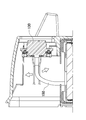
- FIG. 4 is a cross-sectional view taken along line IV-IV of the battery pack of FIG. 1; It is a principal part expanded sectional view which shows the floating connector of the battery pack of FIG. 6A is a bottom view of the floating connector, FIG. 6B is a side view, FIG. 6C is a plan view, and FIG. 6D is a cross-sectional view taken along line VID-VID in FIG. 6B. It is a perspective view which shows the floating connector of FIG.
- FIG. 9A is a plan view showing an example of the notch
- FIG. 9B is a plan view showing another example of the notch
- FIG. 9C is a plan view showing still another example of the notch.
- each element constituting the present invention may be configured such that a plurality of elements are constituted by the same member and one member is used in common as a plurality of elements, or conversely, the function of one member is realized by a plurality of members It can be shared and realized. (Embodiment 1)
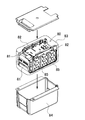
- FIG. 1 is an external perspective view showing the battery pack 100 according to the first embodiment
- FIG. 2 is an external perspective view of the battery pack 100 of FIG. 1 viewed from the back side
- FIG. 3 is the battery pack 100 of FIG. 4 is a cross-sectional view taken along the line IV-IV of the battery pack 100 of FIG. 1
- FIG. 5 is an enlarged cross-sectional view of the main part showing the floating connector 30 of the battery pack 100 of FIG. 6B is a side view
- FIG. 6C is a plan view
- FIG. 6D is a cross-sectional view taken along the line VID-VID in FIG. 6B
- FIG. 7 is a perspective view showing the floating connector 30 in FIG.
- FIG. 9A is a plan view showing an example of the notch 27.
- FIG. 9B is a plan view showing another example of the notch 27.
- FIG. 9C is another example of the notch 27 Indicate Rear view,
- FIG. 10 is a sectional view showing a lead wire 50 according to the modification, respectively. (Exterior case 40)
- the battery pack 100 shown in FIG. 1 and FIG. 2 is configured by a box-shaped outer case 40 in an outer shape.
- a storage space is provided inside the exterior case 40, and the battery assembly 10 is stored.
- the exterior case 40 is divided into a lid side 41 and a body side 42 as shown in FIG. 3 to provide a storage space on the body side.
- the outer case 40 is made of a lightweight material having excellent insulation, such as resin.
- the outer case 40 can be formed with a handle 43 on the upper side and a leg 44 on the bottom side as needed.
- a terminal for charging and a terminal for discharging are provided on the surface of the outer case 40.
- the charging terminal 45 is provided on the top surface side of the outer case 40 as shown in FIG.
- the discharging terminal 46 is provided on the bottom surface side of the outer case 40 as shown in FIG. These terminals may be covered with a cover such as a cap so that the terminal surface is not exposed. In the example of FIG. 1, the charging terminal 45 is covered. Although the charging terminal 45 and the discharging terminal 46 are separately provided in this example, the present invention is not limited to this configuration, and the charging terminal and the discharging terminal 46 may be integrated.
- the recess 47 which is a step lower than the surface of the outer case 40 is formed, and the floating connector 30 is disposed in the recess 47.
- the floating connector 30 can be prevented from protruding from the surface of the outer case 40 and inadvertently coming into contact with foreign matter.
- the opening window 48 is an area for fixing the connector holder 20.
- the opening window 48 is opened at the bottom of the recess 47.
- the battery assembly 10 is accommodated as shown in the cross-sectional view of FIG.
- the battery assembly 10 includes one or more secondary battery cells 1, and these secondary batteries are connected in series or in parallel to obtain a predetermined output or capacity.
- the battery assembly 10 accommodates a plurality of cylindrical secondary battery cells 1 in a battery holder 11 as shown in the exploded perspective view of FIG. 3.
- the battery holder 11 forms a cylindrical cell holding portion that holds the end of the secondary battery cell 1.
- the end face of the secondary battery cell 1 is exposed from the battery holder 11 and welded to the lead plate.
- the secondary battery cells 1 are connected in series or in parallel by the lead plate.
- 28 secondary battery cells 1 are connected in parallel in four rows and seven.
- the shape and arrangement of the lead plates are determined according to the series-parallel connection of the secondary battery cells 1.
- the lead plate is made of a metal having excellent conductivity.
- the lead plate is connected to the end face of the secondary battery cell 1 by spot welding or the like. Furthermore, the lead plate is connected to the circuit board 3.
- the circuit board 3 is disposed on one surface of the battery holder 11. The charge and discharge circuit and the protection circuit of the secondary battery cell 1 are mounted on the circuit board 3.
- the secondary battery cell 1 is a cylindrical battery having a cylindrical outer can.
- a lithium ion secondary battery, a nickel hydrogen secondary battery, a nickel cadmium secondary battery, etc. can be used.
- a lithium ion secondary battery excellent in energy efficiency per unit volume is preferable.
- a plurality of secondary battery cells are connected in series or in parallel by connecting the electrodes of the end faces with a lead plate.
- the shape of the secondary battery cell is not limited to a cylindrical shape, and a square battery, a laminate battery, or the like can also be used.
- the battery assembly 10 can exhibit waterproofness by accommodating in a waterproof container.
- a bag-like container can be used as a waterproof container.
- Such a waterproof bag is made of transparent resin and, for example, polyethylene can be used. In the case where the waterproof function is not provided, the waterproof bag may be omitted. (Connector holder 20)
- the connector holder 20 is exposed from the opening window 48 of the outer case 40. As shown in the enlarged cross sectional view of FIG. 5, the connector holder 20 exposes the first main surface 21 which is one main surface from the opening window 48 of the exterior case 40, and on the opposite side of the first main surface 21. It is fixed to the exterior case 40 in a posture in which the second major surface 22 faces the inside of the exterior case 40. (Floating connector 30)
- the floating connector 30 is attached to the connector holder 20.
- the floating connector 30 serves as a terminal for connecting to the power supply target device to supply power.
- the floating connector 30 constitutes a terminal for discharging.
- the discharge terminal 46 is provided on the exposed surface of the floating connector 30 exposed from the outer case 40. If necessary, a magnet or a metal piece may be provided on the discharge terminal 46 for magnetic connection with the power supply target device. As described above, the bonding can be positioned and the bonding state can be maintained by the bonding by the magnetic force.
- a connector base 32 is provided on the back surface side of the floating connector 30, that is, on the inner surface opposite to the exposed surface.
- the connector base 32 has, for example, a disk shape.
- a lead wire 50 is connected to substantially the center of the connector base 32.
- the lead wire 50 is fixed at substantially the center of the floating connector 30 in a substantially vertical posture.
- the lead wire 50 is extended to the inside of the exterior case 40 and connected to the circuit board 3. (Floating mechanism)
- the floating connector 30 is connected to the connector holder 20 in a floating state in which the X, Y, Z directions and the angle can be changed.
- FIGS. 6A to 6D Three views and a cross-sectional view of the connector holder 20 in which the floating connector 30 is set are shown in FIGS. 6A to 6D.
- the connector holder 20 forms a rectangular frame 23 and opens the first main surface 21 (bottom surface) side to expose the floating connector 30.
- the floating connector 30 is held in a floating state so as to be able to change a certain posture, that is, the angle and the positional deviation in the X, Y, and Z directions, inside the frame 23.
- a certain posture that is, the angle and the positional deviation in the X, Y, and Z directions
- the flat holding plate 24 is fixed in the frame 23, and an opening for disposing the floating connector 30 is formed at the center of the holding plate 24. Furthermore, a flexible connecting member 25 such as bellows or rubber is provided between the periphery of the floating connector 30 and the opening of the holding plate 24 to connect the floating connector 30 and the holding plate 24, thereby deforming the connecting member 25.
- the attitude or the like of the floating connector 30 can be changed by the above. As described above, when the battery pack 100 is connected to the power supply target device by completely fixing the floating connector 30 and allowing some movement, the floating connector 30 and the connector of the power supply target device It becomes possible to absorb the deviation of the relative position and posture of and securely connect.
- the floating connector 30 held by the connector holder 20 in the floating state has a restoring force that returns to the basic state in the absence of an external force while making it possible to change the posture and the like. It is desirable that this basic state be held in a horizontal posture, that is, in a posture substantially parallel to the bottom surface of the exterior case 40 and at a substantially central position of the opening of the holding plate 24. As a result, when the battery pack 100 is set to the power supply target device, the floating connector 30 is easily joined to the connector of the power supply target device. In the example of FIG. 5, the floating connector 30 is configured to be horizontal to the plane of the holding plate 24.
- Such a connector holder 20 and the floating connector 30 can also use standardized members. This makes it possible to correct the posture of the floating connector to the basic posture at the center and use it while utilizing the existing lead wire type floating connector.
- the floating connector 30 is provided in the recess 47 of the connector holder 20, and the lead wire 50 is further standardized in a state of being connected to the floating connector 30.
- the frame 23 of the connector holder 20 is formed in a rectangular shape in the example of FIG. 6A and the like, the present invention is not limited to this configuration, and for example, the frame may be formed in a cylindrical shape. (Guide cylinder 26)
- the second main surface 22 (top surface) side of the connector holder 20 is closed, and a cylindrical guide cylinder 26 is connected substantially at the center.
- the frame body 23 and the guide cylinder 26 are formed such that the internal space of the frame body 23 and the inner surface of the cylinder of the guide cylinder 26 are connected.
- the frame 23 and the guide cylinder 26 are integrally formed.
- the guide cylinder 26 is fixed to the second main surface 22 of the connector holder 20 substantially perpendicularly.
- the guide cylinder 26 inserts the lead wire 50 fixed to the back surface of the connector holder 20. As a result, the lead wire 50 is held in a substantially vertical posture, and it is possible to avoid a situation where a bias is applied in a state where the posture of the floating connector 30 connected to the lead wire 50 deviates from the basic posture.
- the original basic state should be restored when the external force disappears. It may be disturbed and it may be in the state which does not return to a basic state.
- the floating function may be disturbed by the lead wire connected to the floating connector in this manner.
- the cylindrical guide cylinder 26 surrounding the lead wire 50 is provided on the second main surface 22 side of the connector holder 20. It is provided.
- the guide cylinder 26 is provided substantially perpendicularly to the second main surface 22 side.
- the guide cylinder 26 is provided in the vicinity of the joint portion between the lead wire 50 and the floating connector 30, and the lead wire 50 in the vicinity of the joint portion By holding at this position, it is possible to make the basic state of the floating connector 30 approach a horizontal posture. In other words, even if the biasing force of the lead wire 50 acts, the guide cylinder 26 can correct the horizontal posture in the vicinity of the joint portion between the lead wire 50 and the floating connector 30.
- the inner diameter of the guide cylinder 26 is larger than the outer diameter of the lead wire 50 as shown in FIG. 5, FIG. 6D, FIG. 7, etc. so that the floating mechanism of the floating connector 30 is not obstructed by the guide cylinder 26. I also make it a little bigger. As a result, a space is formed around the lead wire 50, so that some movement or deformation in the space is allowed, and the floating connector 30 connected to the lead wire 50 can also be tilted. It is held. (Friction reduction mechanism)
- the friction reduction mechanism for reducing the friction between the outer periphery of the lead wire 50 and the inner wall of the guide cylinder 26.
- the cylindrical guide cylinder 26 is provided with the notch 27 in a part of a circular shape in a cross sectional view. With this configuration, the contact area of the lead wire 50 guided into the guide cylinder 26 can be reduced.
- the contact area between the lead wire in a circular cross-sectional view and the guide cylinder in a circular cross-sectional view is a contact between the curved surface and the curved surface, the contact area tends to be large.
- the contact area between them can be reduced, and the effect of reducing the frictional resistance can be obtained accordingly.
- a rib 28 for reinforcing the guide cylinder 26 may be provided in a region where the notch portion 27 is provided.
- three ribs 28 are made to project to the outside of the notch 27.
- the rib 28 is formed such that the top of the rib 28 follows the circular shape of the cross section of the guide cylinder 26 in a plan view. Thereby, the strength can be maintained while forming the notch 27 in the guide cylinder 26.
- the shape of the end face of the notch 27 preferably makes the radius of curvature larger than the radius of curvature of the circular shape of the cross section of the guide cylinder 26.
- a notch 27A provided in a guide cylinder 26A shown in FIG. 9A it has a linear shape with an infinite radius of curvature.
- the contact area can be reduced as compared with the circular guide cylinder 26.
- the shape of the notch portion is not limited to a linear shape, and may be curved.
- FIG. 9B by forming the notched portion 27B provided in the guide cylinder 26B in a curved shape, the contact area can be reduced as compared with the case where the guide cylinder 26B remains circular.
- a region in which the lead wire 50 can move inside the guide cylinder 26B can be widely secured as compared with a linear notch, and the tiltable range of the floating connector 30 can be maintained wide.
- the position where the notch 27 is formed is determined according to the position of the circuit board 3 to which the lead wire 50 is fixed. For example, it is positioned at the end edge of the guide cylinder 26 on the side far from the circuit board 3.
- the lead wire 50 can be disposed at a long distance rather than at the shortest distance to the circuit board 3 to improve the handling of the lead wire 50 and improve the workability at the time of assembly work. It is possible to allow the floating connector 30 to be easily tilted.
- the lead wire is made longer, it will not be connected at the shortest distance to the circuit board, but it will be drawn by bending an arc so as to divert it once.
- the inner surface of the guide cylinder comes in contact with the lead wire in the direction in which the lead wire is bent. Therefore, the notch 27 for reducing the contact area is provided on the side away from the circuit board 3, that is, on the side far from the circuit board 3 to bring the notch 27 into contact with the lead wire 50. It becomes possible to exhibit sliding property effectively.
- the notch 27 is horizontal to the edge of the circuit board 3 as in the notch 27A shown in FIG. 9A and the like, and as shown in FIG. Preferably, it is inclined in the direction of withdrawal.
- the connection position of the circuit board 3 and the lead wire 50 is on the left side of the upper end of the circuit board 3, and the lead wire 50 is drawn rightward from here, and then folded back into a U shape and floating connector Connected to 30. That is, the lead wire 50 is disposed so as to be connected to the floating connector 30 after the lead wire 50 is drawn and detoured on the right side. In this configuration, the right inner wall on the right and left of the guide cylinder 26 is likely to come in contact with the lead wire 50.
- the long lead wire 50 drawn out from the circuit board 3 is once bypassed over the guide cylinder 26 and then connected to the floating connector 30.
- the upper and lower inner walls of the guide cylinder 26 are more likely to come in contact with the lead wire 50. Therefore, in consideration of these, it can be said that the notch 27 is likely to contact the upper side and the right side in the guide cylinder 26. Therefore, as described above, the notch is inclined downward from the horizontal attitude with respect to the edge of the circuit board 3 in the direction in which the lead wire 50 is drawn from the circuit board 3 to the right in the example of FIG.
- the notch 27 can be disposed so as to face the portion where the frictional force by the lead wire 50 drawn out from the circuit board 3 acts, thereby ensuring the reliability of bringing the lead wire 50 into contact with the notch 27 It is possible to enhance the sliding property of the contact portion effectively and obtain a smooth floating operation. (Wound tape 52)
- the lead wire 50 may be wound around with a winding tape 52 whose surface is smooth.
- the winding tape 52 can be made of a material having a low coefficient of friction, such as polypropylene.
- the lead wire 50 may be comprised by not only one but multiple. Also, the material and thickness of multiple lead wires may vary. In such a case, by bundling one by one with the winding tape 52, the handling inside the exterior case 40 is improved, and the workability at the time of assembly and maintenance can be improved. In addition, by setting the position to be wound by the winding tape 52 to a position where the guide cylinder 26 and the lead wire 50 contact with each other, the sliding movement is enhanced and the frictional resistance is reduced as described above. You can get the effect of making sure. (Fixing part 29)
- the connector holder 20 can also be provided with a fixing portion 29 for inserting and fixing the opening window 48 of the exterior case 40 from the inside of the exterior case 40.
- the lead wires 50 welded in advance to the floating connector 30 are directly connected to the circuit board 3 without the necessity of a relay connector required in the structure for fixing the connector holder 20 from the outside of the outer case 40. Can be assembled.
- the mounting of the outer case 40 can be performed at the end of the assembly process, which also contributes to the improvement of the assembly workability.
- a known fixing structure such as a screw hole for screwing with a screw 60 from the inside of the outer case 40 can be appropriately used.
- the battery assembly 10 and the circuit board 3 are disposed in the outer case 40, the lead wire 50 is drawn from the circuit board 3, and the cylindrical guide cylinder 26 formed on the second main surface 22 side of the connector holder 20 is formed. Then, the lead wire 50 is connected to the floating connector 30, and the connector holder 20 is inserted from the inner surface side of the outer case 40 into the opening window 48 of the outer case 40 and fixed. In this state, the outer case 40 is closed. As a result, by guiding the lead wire 50 into the guide cylinder 26, the position of the floating connector 30 is corrected centering on the guide cylinder 26 of the connector holder 20, and the floating function is impaired by the tension of the lead wire 50 or the like. It is possible to suppress the switching function and to realize the floating function to ensure the flexibility of the engagement between the battery pack 100 and the power supply target device.
- the battery pack can be suitably used as a power source for an electric power tool, an electric power assisted bicycle, an electric motorbike, a hybrid electric car, an electric car or the like .
- Battery pack 1 Secondary battery cell 3 Circuit board 10 Battery assembly 11 Battery holder 20 Connector holder 21 First main surface 22 Second main surface 23 Frame 24 Holding plate 25 Connection Material 26, 26A, 26B, 26C ... Guide cylinder 27, 27A, 27B, 27C ... Notched part 28 ... Rib 29 ... Fixed part 30, 130 ... Floating connector 32 ... Connector base 40, 140 ... Outer case 41 ... Lid side 42 ... Body side 43 ... Handle 44 ... Leg 45 ... Charging terminal 46 ... Discharge terminal 47 ... Depression 48 ... Opening window 50, 150 ... Lead wire 52 ... Winding tape 60, 160 ... Screw 80 ... Battery assembly 81 ... Battery cell 82: Battery holder 83: Waterproof container 84: Exterior case 85: Lead plate
Landscapes
- Engineering & Computer Science (AREA)
- Manufacturing & Machinery (AREA)
- Chemical & Material Sciences (AREA)
- Chemical Kinetics & Catalysis (AREA)
- Electrochemistry (AREA)
- General Chemical & Material Sciences (AREA)
- Microelectronics & Electronic Packaging (AREA)
- Battery Mounting, Suspending (AREA)
- Details Of Connecting Devices For Male And Female Coupling (AREA)
Abstract
Description
(実施形態1)
(外装ケース40)
(電池集合体10)
(コネクタホルダ20)
(フローティングコネクタ30)
(フローティング機構)
(ガイド筒26)
(摩擦低減機構)
(捲回テープ52)
(固定部29)
(電池パック100の製造方法)
1…二次電池セル
3…回路基板
10…電池集合体
11…電池ホルダ
20…コネクタホルダ
21…第一主面
22…第二主面
23…枠体
24…保持板
25…連結材
26、26A、26B、26C…ガイド筒
27、27A、27B、27C…切り欠き部
28…リブ
29…固定部
30、130…フローティングコネクタ
32…コネクタベース
40、140…外装ケース
41…蓋側
42…本体側
43…取っ手
44…脚部
45…充電用端子
46…放電用端子
47…窪み
48…開口窓
50、150…リード線
52…捲回テープ
60、160…ねじ
80…電池集合体
81…電池セル
82…電池ホルダ
83…防水容器
84…外装ケース
85…リード板
Claims (10)
- 一以上の二次電池セルを含む電池集合体と、
前記電池集合体を収納すると共に開口窓を形成した外装ケースと、
前記電池集合体の二次電池セルと電気的に接続される回路基板と、
一方の主面である第一主面を前記外装ケースの開口窓から表出させ、他方の主面であって前記第一主面の反対側である第二主面を前記外装ケースの内側に向けた姿勢に、前記外装ケースに固定されるコネクタホルダと、
前記コネクタホルダの中央部分に、姿勢を上下左右に変更可能なフローティング状態で連結され、前記外装ケースから表出される表出面を電力供給対象機器と接続して電力を供給するためのフローティングコネクタと、
前記フローティングコネクタの、表出面と反対側の内側面に固定され、前記外装ケースの内部に延出されて、前記フローティングコネクタと回路基板とを接続するリード線と、
を備える電池パックであって、
前記コネクタホルダが、前記第二主面側に、前記リード線の周囲を囲む筒状のガイド筒を有しており、
前記ガイド筒が、その端縁の形状を、円形状の一部に、該円形状の曲率半径よりも曲率半径を大きくした切り欠き部を設けた形状としてなる電池パック。 - 請求項1に記載の電池パックであって、
前記リード線は、前記フローティングコネクタの内側面の中央部分から、垂直状の姿勢で固定されてなる電池パック。 - 請求項1又は2に記載の電池パックであって、
前記切り欠き部が、直線状又は湾曲されてなる電池パック。 - 請求項1~3のいずれか一項に記載の電池パックであって、
前記切り欠き部が、前記ガイド筒の端縁において、前記回路基板から遠い側に位置されてなる電池パック。 - 請求項4に記載の電池パックであって、
前記切り欠き部が、前記ガイド筒・BR>フ端縁において、該回路基板から前記リード線が引き出される方向に傾斜されてなる電池パック。 - 請求項1~5のいずれか一項に記載の電池パックであって、
前記コネクタホルダが、前記ガイド筒から連なって、該ガイド筒よりも内径を大きくして、前記フローティングコネクタの周囲を囲む枠体を形成してなる電池パック。 - 請求項1~6のいずれか一項に記載の電池パックであって、
前記コネクタホルダが、前記外装ケースの開口窓に、該外装ケースの内側から挿入して固定するための固定部を有してなる電池パック。 - 請求項1~7のいずれか一項に記載の電池パックであって、
前記リード線が複数本の線で構成されてなる電池パック。 - 請求項1~8のいずれか一項に記載の電池パックであって、
前記リード線の周囲を、表面を平滑状とした捲回テープで捲回してなる電池パック。 - 一以上の二次電池セルを含む電池集合体と、
前記電池集合体を収納すると共に開口窓を形成した外装ケースと、
前記電池集合体の二次電池セルと電気的に接続される回路基板と、
一方の主面である第一主面を前記外装ケースの開口窓から表出させ、他方の主面であって前記第一主面の反対側である第二主面を前記外装ケースの内側に向けた姿勢に、前記外装ケースに固定されるコネクタホルダと、
前記コネクタホルダに、角度を変更可能なフローティング状態で連結され、電力供給対象機器と接続して電力を供給するためのフローティングコネクタと、
前記外装ケースの内部に延出されて、前記フローティングコネクタと回路基板とを接続するリード線と、
を備える電池パックの製造方法であって、
前記外装ケース内に前記電池集合体と回路基板を配置し、該回路基板から前記リード線を引き出し、前記コネクタホルダの第二主面側に形成された筒状のガイド筒であってその端縁の形状を、円形状の一部に、該円形状の曲率半径よりも曲率半径を大きくした切り欠き部を設けた形状としているガイド筒にリード線を通した状態で該リード線を前記フローティングコネクタに接続し、前記外装ケースの内面側から、前記コネクタホルダを、前記外装ケースの開口窓に挿入して、固定する工程と、
前記外装ケースを閉塞する工程と、
を含む電池パックの製造方法。
Priority Applications (5)
| Application Number | Priority Date | Filing Date | Title |
|---|---|---|---|
| NZ761688A NZ761688A (en) | 2017-07-27 | 2018-07-23 | Battery pack and production method for same |
| JP2019532578A JP7112401B2 (ja) | 2017-07-27 | 2018-07-23 | 電池パック及びその製造方法 |
| EP18838494.5A EP3660946B1 (en) | 2017-07-27 | 2018-07-23 | Battery pack and production method for same |
| US16/633,054 US11424516B2 (en) | 2017-07-27 | 2018-07-23 | Battery pack and production method for same |
| AU2018307011A AU2018307011B2 (en) | 2017-07-27 | 2018-07-23 | Battery pack and production method for same |
Applications Claiming Priority (2)
| Application Number | Priority Date | Filing Date | Title |
|---|---|---|---|
| JP2017145920 | 2017-07-27 | ||
| JP2017-145920 | 2017-07-27 |
Publications (1)
| Publication Number | Publication Date |
|---|---|
| WO2019021979A1 true WO2019021979A1 (ja) | 2019-01-31 |
Family
ID=65040250
Family Applications (1)
| Application Number | Title | Priority Date | Filing Date |
|---|---|---|---|
| PCT/JP2018/027414 Ceased WO2019021979A1 (ja) | 2017-07-27 | 2018-07-23 | 電池パック及びその製造方法 |
Country Status (6)
| Country | Link |
|---|---|
| US (1) | US11424516B2 (ja) |
| EP (1) | EP3660946B1 (ja) |
| JP (1) | JP7112401B2 (ja) |
| AU (1) | AU2018307011B2 (ja) |
| NZ (1) | NZ761688A (ja) |
| WO (1) | WO2019021979A1 (ja) |
Cited By (4)
| Publication number | Priority date | Publication date | Assignee | Title |
|---|---|---|---|---|
| CN110556653A (zh) * | 2019-10-10 | 2019-12-10 | 上海先惠自动化技术股份有限公司 | 一种数据线接头自动对接机构 |
| CN110571581A (zh) * | 2019-10-10 | 2019-12-13 | 上海先惠自动化技术股份有限公司 | 一种高压接头自动对接机构 |
| WO2021090633A1 (ja) * | 2019-11-06 | 2021-05-14 | 日本端子株式会社 | コネクタ接続構造 |
| JP2023528794A (ja) * | 2020-05-28 | 2023-07-06 | グリフ アビエーション エーエス | バッテリーコネクタ |
Families Citing this family (1)
| Publication number | Priority date | Publication date | Assignee | Title |
|---|---|---|---|---|
| US12160127B2 (en) | 2021-12-09 | 2024-12-03 | Honda Motor Co., Ltd. | Battery terminal fixing apparatus and method for power equipment |
Citations (7)
| Publication number | Priority date | Publication date | Assignee | Title |
|---|---|---|---|---|
| JPH0251616A (ja) | 1988-08-16 | 1990-02-21 | Canon Inc | フローティングコネクタ |
| JPH06296773A (ja) * | 1993-03-20 | 1994-10-25 | Braun Ag | 電気器具 |
| JP2006147115A (ja) * | 2004-11-25 | 2006-06-08 | Sanyo Electric Co Ltd | 光ディスク装置 |
| JP2008251214A (ja) * | 2007-03-29 | 2008-10-16 | Harada Ind Co Ltd | 接続端子構造 |
| JP2012205371A (ja) * | 2011-03-24 | 2012-10-22 | Sanyo Electric Co Ltd | 携帯式電源装置 |
| WO2014162963A1 (ja) * | 2013-04-03 | 2014-10-09 | Necエナジーデバイス株式会社 | 電池モジュール |
| WO2016072041A1 (ja) | 2014-11-07 | 2016-05-12 | 三洋電機株式会社 | 電源装置 |
Family Cites Families (14)
| Publication number | Priority date | Publication date | Assignee | Title |
|---|---|---|---|---|
| US5144217A (en) * | 1989-03-03 | 1992-09-01 | Black & Decker Inc. | Cordless tool battery housing and charging system |
| JP5110777B2 (ja) * | 2005-06-29 | 2012-12-26 | 三洋電機株式会社 | パック電池 |
| DE102009012180A1 (de) * | 2009-02-27 | 2010-09-02 | Andreas Stihl Ag & Co. Kg | Akkupack für ein Elektrowerkzeug |
| DE102009012184A1 (de) * | 2009-02-27 | 2010-09-02 | Andreas Stihl Ag & Co. Kg | Tragbares, handgeführtes Elektrogerät mit einem Akkupack |
| JP5593894B2 (ja) * | 2009-07-30 | 2014-09-24 | スズキ株式会社 | 電動の乗り物に脱着されるバッテリパックとこのバッテリパックを備える電動の乗り物 |
| JP5573471B2 (ja) * | 2010-08-05 | 2014-08-20 | スズキ株式会社 | バッテリパック |
| US8765297B2 (en) * | 2011-01-04 | 2014-07-01 | Exide Technologies | Advanced graphite additive for enhanced cycle-life of lead-acid batteries |
| ES2928852T3 (es) * | 2015-06-05 | 2022-11-23 | Milwaukee Electric Tool Corp | Elemento de soporte para carcasa superior de batería |
| EP3162513B1 (en) * | 2015-10-30 | 2019-04-17 | Black & Decker Inc. | High power brushless motor |
| CN206441961U (zh) * | 2016-09-21 | 2017-08-25 | 蔚来汽车有限公司 | 电动汽车液冷电池包的连接器 |
| US11859271B2 (en) * | 2017-05-04 | 2024-01-02 | Regents Of The University Of Minnesota | Iron nitride compositions |
| JP7177652B2 (ja) * | 2018-10-11 | 2022-11-24 | 株式会社マキタ | 背負式機器 |
| KR102654288B1 (ko) * | 2019-01-09 | 2024-04-05 | 비와이디 컴퍼니 리미티드 | 배터리 팩, 차량, 및 에너지 저장 디바이스 |
| US11477885B2 (en) * | 2020-09-30 | 2022-10-18 | Inventus Power, Inc. | Redundant trace fuse for a conformal wearable battery |
-
2018
- 2018-07-23 WO PCT/JP2018/027414 patent/WO2019021979A1/ja not_active Ceased
- 2018-07-23 JP JP2019532578A patent/JP7112401B2/ja active Active
- 2018-07-23 NZ NZ761688A patent/NZ761688A/en unknown
- 2018-07-23 EP EP18838494.5A patent/EP3660946B1/en active Active
- 2018-07-23 AU AU2018307011A patent/AU2018307011B2/en active Active
- 2018-07-23 US US16/633,054 patent/US11424516B2/en active Active
Patent Citations (7)
| Publication number | Priority date | Publication date | Assignee | Title |
|---|---|---|---|---|
| JPH0251616A (ja) | 1988-08-16 | 1990-02-21 | Canon Inc | フローティングコネクタ |
| JPH06296773A (ja) * | 1993-03-20 | 1994-10-25 | Braun Ag | 電気器具 |
| JP2006147115A (ja) * | 2004-11-25 | 2006-06-08 | Sanyo Electric Co Ltd | 光ディスク装置 |
| JP2008251214A (ja) * | 2007-03-29 | 2008-10-16 | Harada Ind Co Ltd | 接続端子構造 |
| JP2012205371A (ja) * | 2011-03-24 | 2012-10-22 | Sanyo Electric Co Ltd | 携帯式電源装置 |
| WO2014162963A1 (ja) * | 2013-04-03 | 2014-10-09 | Necエナジーデバイス株式会社 | 電池モジュール |
| WO2016072041A1 (ja) | 2014-11-07 | 2016-05-12 | 三洋電機株式会社 | 電源装置 |
Non-Patent Citations (1)
| Title |
|---|
| See also references of EP3660946A4 |
Cited By (8)
| Publication number | Priority date | Publication date | Assignee | Title |
|---|---|---|---|---|
| CN110556653A (zh) * | 2019-10-10 | 2019-12-10 | 上海先惠自动化技术股份有限公司 | 一种数据线接头自动对接机构 |
| CN110571581A (zh) * | 2019-10-10 | 2019-12-13 | 上海先惠自动化技术股份有限公司 | 一种高压接头自动对接机构 |
| WO2021090633A1 (ja) * | 2019-11-06 | 2021-05-14 | 日本端子株式会社 | コネクタ接続構造 |
| JP2021077466A (ja) * | 2019-11-06 | 2021-05-20 | 日本端子株式会社 | コネクタ接続構造 |
| CN114641903A (zh) * | 2019-11-06 | 2022-06-17 | 日本端子株式会社 | 连接器连接结构 |
| CN114641903B (zh) * | 2019-11-06 | 2024-07-30 | 日本端子株式会社 | 连接器连接结构 |
| JP2023528794A (ja) * | 2020-05-28 | 2023-07-06 | グリフ アビエーション エーエス | バッテリーコネクタ |
| JP7775229B2 (ja) | 2020-05-28 | 2025-11-25 | グリフ アビエーション エーエス | バッテリーコネクタ |
Also Published As
| Publication number | Publication date |
|---|---|
| EP3660946A4 (en) | 2020-07-08 |
| AU2018307011A1 (en) | 2020-02-27 |
| JP7112401B2 (ja) | 2022-08-03 |
| EP3660946A1 (en) | 2020-06-03 |
| JPWO2019021979A1 (ja) | 2020-06-11 |
| US20200235366A1 (en) | 2020-07-23 |
| EP3660946B1 (en) | 2026-02-25 |
| NZ761688A (en) | 2026-01-30 |
| US11424516B2 (en) | 2022-08-23 |
| AU2018307011B2 (en) | 2024-02-08 |
Similar Documents
| Publication | Publication Date | Title |
|---|---|---|
| WO2019021979A1 (ja) | 電池パック及びその製造方法 | |
| US12347891B2 (en) | Button cell comprising a direction determining member | |
| JP5518432B2 (ja) | 円筒形電池を内蔵可能な携帯式電源装置 | |
| JP5518576B2 (ja) | 電池パック | |
| US8663827B2 (en) | Battery pack | |
| US12224459B2 (en) | Button cell | |
| KR20180135701A (ko) | 배터리 모듈 | |
| KR102210461B1 (ko) | 단위전지모듈과 이를 포함하는 전지모듈 및 전지모듈의 제조방법과 이를 포함하는 전지팩 | |
| JP2020514953A (ja) | バッテリーパック | |
| JP5337783B2 (ja) | バッテリパック | |
| US20170271721A1 (en) | Battery pack | |
| JP6526403B2 (ja) | 二次電池 | |
| JP7160809B2 (ja) | 電池パック及びその製造方法 | |
| JP5512152B2 (ja) | パック電池 | |
| US20150072218A1 (en) | Battery pack and battery module including the same | |
| JP2005183157A (ja) | 薄型バッテリーパック | |
| KR20210049327A (ko) | 방식 부재가 구비된 버스 바 및 이를 포함하는 배터리 모듈 | |
| JP4553706B2 (ja) | 電池パック | |
| WO2020174953A1 (ja) | 蓄電装置 | |
| KR20240059428A (ko) | 버스바를 일체로 구비하는 단자 구조체 어셈블리 | |
| CN104037366A (zh) | 可再充电电池组 | |
| KR20230011872A (ko) | 축전 장치 및 그 차량 탑재 구조 | |
| CN115699421B (zh) | 电池模块、包括该电池模块的电池组以及车辆 | |
| JP4841205B2 (ja) | リード線付きリチウムイオン電池パック | |
| JP2018200761A (ja) | 電池パック及びこれを備える電源装置並びに電池パックの製造方法 |
Legal Events
| Date | Code | Title | Description |
|---|---|---|---|
| 121 | Ep: the epo has been informed by wipo that ep was designated in this application |
Ref document number: 18838494 Country of ref document: EP Kind code of ref document: A1 |
|
| ENP | Entry into the national phase |
Ref document number: 2019532578 Country of ref document: JP Kind code of ref document: A |
|
| NENP | Non-entry into the national phase |
Ref country code: DE |
|
| ENP | Entry into the national phase |
Ref document number: 2018307011 Country of ref document: AU Date of ref document: 20180723 Kind code of ref document: A |
|
| ENP | Entry into the national phase |
Ref document number: 2018838494 Country of ref document: EP Effective date: 20200227 |
|
| WWG | Wipo information: grant in national office |
Ref document number: 2018838494 Country of ref document: EP |