WO2019022024A1 - 偏光板の製造方法及び表示装置の製造方法 - Google Patents
偏光板の製造方法及び表示装置の製造方法 Download PDFInfo
- Publication number
- WO2019022024A1 WO2019022024A1 PCT/JP2018/027549 JP2018027549W WO2019022024A1 WO 2019022024 A1 WO2019022024 A1 WO 2019022024A1 JP 2018027549 W JP2018027549 W JP 2018027549W WO 2019022024 A1 WO2019022024 A1 WO 2019022024A1
- Authority
- WO
- WIPO (PCT)
- Prior art keywords
- polarizing plate
- film
- stretching
- material film
- laminate
- Prior art date
- Legal status (The legal status is an assumption and is not a legal conclusion. Google has not performed a legal analysis and makes no representation as to the accuracy of the status listed.)
- Ceased
Links
Images





Classifications
-
- B—PERFORMING OPERATIONS; TRANSPORTING
- B32—LAYERED PRODUCTS
- B32B—LAYERED PRODUCTS, i.e. PRODUCTS BUILT-UP OF STRATA OF FLAT OR NON-FLAT, e.g. CELLULAR OR HONEYCOMB, FORM
- B32B7/00—Layered products characterised by the relation between layers; Layered products characterised by the relative orientation of features between layers, or by the relative values of a measurable parameter between layers, i.e. products comprising layers having different physical, chemical or physicochemical properties; Layered products characterised by the interconnection of layers
- B32B7/02—Physical, chemical or physicochemical properties
- B32B7/023—Optical properties
-
- B—PERFORMING OPERATIONS; TRANSPORTING
- B29—WORKING OF PLASTICS; WORKING OF SUBSTANCES IN A PLASTIC STATE IN GENERAL
- B29C—SHAPING OR JOINING OF PLASTICS; SHAPING OF MATERIAL IN A PLASTIC STATE, NOT OTHERWISE PROVIDED FOR; AFTER-TREATMENT OF THE SHAPED PRODUCTS, e.g. REPAIRING
- B29C55/00—Shaping by stretching, e.g. drawing through a die; Apparatus therefor
- B29C55/02—Shaping by stretching, e.g. drawing through a die; Apparatus therefor of plates or sheets
- B29C55/04—Shaping by stretching, e.g. drawing through a die; Apparatus therefor of plates or sheets uniaxial, e.g. oblique
-
- B—PERFORMING OPERATIONS; TRANSPORTING
- B32—LAYERED PRODUCTS
- B32B—LAYERED PRODUCTS, i.e. PRODUCTS BUILT-UP OF STRATA OF FLAT OR NON-FLAT, e.g. CELLULAR OR HONEYCOMB, FORM
- B32B27/00—Layered products comprising a layer of synthetic resin
- B32B27/18—Layered products comprising a layer of synthetic resin characterised by the use of special additives
- B32B27/20—Layered products comprising a layer of synthetic resin characterised by the use of special additives using fillers, pigments, thixotroping agents
-
- B—PERFORMING OPERATIONS; TRANSPORTING
- B32—LAYERED PRODUCTS
- B32B—LAYERED PRODUCTS, i.e. PRODUCTS BUILT-UP OF STRATA OF FLAT OR NON-FLAT, e.g. CELLULAR OR HONEYCOMB, FORM
- B32B27/00—Layered products comprising a layer of synthetic resin
- B32B27/18—Layered products comprising a layer of synthetic resin characterised by the use of special additives
- B32B27/22—Layered products comprising a layer of synthetic resin characterised by the use of special additives using plasticisers
-
- B—PERFORMING OPERATIONS; TRANSPORTING
- B32—LAYERED PRODUCTS
- B32B—LAYERED PRODUCTS, i.e. PRODUCTS BUILT-UP OF STRATA OF FLAT OR NON-FLAT, e.g. CELLULAR OR HONEYCOMB, FORM
- B32B27/00—Layered products comprising a layer of synthetic resin
- B32B27/30—Layered products comprising a layer of synthetic resin comprising vinyl (co)polymers; comprising acrylic (co)polymers
-
- B—PERFORMING OPERATIONS; TRANSPORTING
- B32—LAYERED PRODUCTS
- B32B—LAYERED PRODUCTS, i.e. PRODUCTS BUILT-UP OF STRATA OF FLAT OR NON-FLAT, e.g. CELLULAR OR HONEYCOMB, FORM
- B32B27/00—Layered products comprising a layer of synthetic resin
- B32B27/30—Layered products comprising a layer of synthetic resin comprising vinyl (co)polymers; comprising acrylic (co)polymers
- B32B27/306—Layered products comprising a layer of synthetic resin comprising vinyl (co)polymers; comprising acrylic (co)polymers comprising vinyl acetate or vinyl alcohol (co)polymers
-
- B—PERFORMING OPERATIONS; TRANSPORTING
- B32—LAYERED PRODUCTS
- B32B—LAYERED PRODUCTS, i.e. PRODUCTS BUILT-UP OF STRATA OF FLAT OR NON-FLAT, e.g. CELLULAR OR HONEYCOMB, FORM
- B32B27/00—Layered products comprising a layer of synthetic resin
- B32B27/32—Layered products comprising a layer of synthetic resin comprising polyolefins
- B32B27/325—Layered products comprising a layer of synthetic resin comprising polyolefins comprising polycycloolefins
-
- B—PERFORMING OPERATIONS; TRANSPORTING
- B32—LAYERED PRODUCTS
- B32B—LAYERED PRODUCTS, i.e. PRODUCTS BUILT-UP OF STRATA OF FLAT OR NON-FLAT, e.g. CELLULAR OR HONEYCOMB, FORM
- B32B37/00—Methods or apparatus for laminating, e.g. by curing or by ultrasonic bonding
- B32B37/12—Methods or apparatus for laminating, e.g. by curing or by ultrasonic bonding characterised by using adhesives
-
- B—PERFORMING OPERATIONS; TRANSPORTING
- B32—LAYERED PRODUCTS
- B32B—LAYERED PRODUCTS, i.e. PRODUCTS BUILT-UP OF STRATA OF FLAT OR NON-FLAT, e.g. CELLULAR OR HONEYCOMB, FORM
- B32B38/00—Ancillary operations in connection with laminating processes
- B32B38/0012—Mechanical treatment, e.g. roughening, deforming, stretching
-
- B—PERFORMING OPERATIONS; TRANSPORTING
- B32—LAYERED PRODUCTS
- B32B—LAYERED PRODUCTS, i.e. PRODUCTS BUILT-UP OF STRATA OF FLAT OR NON-FLAT, e.g. CELLULAR OR HONEYCOMB, FORM
- B32B7/00—Layered products characterised by the relation between layers; Layered products characterised by the relative orientation of features between layers, or by the relative values of a measurable parameter between layers, i.e. products comprising layers having different physical, chemical or physicochemical properties; Layered products characterised by the interconnection of layers
- B32B7/02—Physical, chemical or physicochemical properties
-
- B—PERFORMING OPERATIONS; TRANSPORTING
- B32—LAYERED PRODUCTS
- B32B—LAYERED PRODUCTS, i.e. PRODUCTS BUILT-UP OF STRATA OF FLAT OR NON-FLAT, e.g. CELLULAR OR HONEYCOMB, FORM
- B32B7/00—Layered products characterised by the relation between layers; Layered products characterised by the relative orientation of features between layers, or by the relative values of a measurable parameter between layers, i.e. products comprising layers having different physical, chemical or physicochemical properties; Layered products characterised by the interconnection of layers
- B32B7/03—Layered products characterised by the relation between layers; Layered products characterised by the relative orientation of features between layers, or by the relative values of a measurable parameter between layers, i.e. products comprising layers having different physical, chemical or physicochemical properties; Layered products characterised by the interconnection of layers with respect to the orientation of features
- B32B7/035—Layered products characterised by the relation between layers; Layered products characterised by the relative orientation of features between layers, or by the relative values of a measurable parameter between layers, i.e. products comprising layers having different physical, chemical or physicochemical properties; Layered products characterised by the interconnection of layers with respect to the orientation of features using arrangements of stretched films, e.g. of mono-axially stretched films arranged alternately
-
- B—PERFORMING OPERATIONS; TRANSPORTING
- B32—LAYERED PRODUCTS
- B32B—LAYERED PRODUCTS, i.e. PRODUCTS BUILT-UP OF STRATA OF FLAT OR NON-FLAT, e.g. CELLULAR OR HONEYCOMB, FORM
- B32B7/00—Layered products characterised by the relation between layers; Layered products characterised by the relative orientation of features between layers, or by the relative values of a measurable parameter between layers, i.e. products comprising layers having different physical, chemical or physicochemical properties; Layered products characterised by the interconnection of layers
- B32B7/04—Interconnection of layers
- B32B7/12—Interconnection of layers using interposed adhesives or interposed materials with bonding properties
-
- G—PHYSICS
- G02—OPTICS
- G02B—OPTICAL ELEMENTS, SYSTEMS OR APPARATUS
- G02B5/00—Optical elements other than lenses
- G02B5/30—Polarising elements
-
- G—PHYSICS
- G02—OPTICS
- G02F—OPTICAL DEVICES OR ARRANGEMENTS FOR THE CONTROL OF LIGHT BY MODIFICATION OF THE OPTICAL PROPERTIES OF THE MEDIA OF THE ELEMENTS INVOLVED THEREIN; NON-LINEAR OPTICS; FREQUENCY-CHANGING OF LIGHT; OPTICAL LOGIC ELEMENTS; OPTICAL ANALOGUE/DIGITAL CONVERTERS
- G02F1/00—Devices or arrangements for the control of the intensity, colour, phase, polarisation or direction of light arriving from an independent light source, e.g. switching, gating or modulating; Non-linear optics
- G02F1/01—Devices or arrangements for the control of the intensity, colour, phase, polarisation or direction of light arriving from an independent light source, e.g. switching, gating or modulating; Non-linear optics for the control of the intensity, phase, polarisation or colour
- G02F1/13—Devices or arrangements for the control of the intensity, colour, phase, polarisation or direction of light arriving from an independent light source, e.g. switching, gating or modulating; Non-linear optics for the control of the intensity, phase, polarisation or colour based on liquid crystals, e.g. single liquid crystal display cells
- G02F1/133—Constructional arrangements; Operation of liquid crystal cells; Circuit arrangements
- G02F1/1333—Constructional arrangements; Manufacturing methods
- G02F1/1335—Structural association of cells with optical devices, e.g. polarisers or reflectors
-
- G—PHYSICS
- G09—EDUCATION; CRYPTOGRAPHY; DISPLAY; ADVERTISING; SEALS
- G09F—DISPLAYING; ADVERTISING; SIGNS; LABELS OR NAME-PLATES; SEALS
- G09F9/00—Indicating arrangements for variable information in which the information is built-up on a support by selection or combination of individual elements
-
- G—PHYSICS
- G09—EDUCATION; CRYPTOGRAPHY; DISPLAY; ADVERTISING; SEALS
- G09F—DISPLAYING; ADVERTISING; SIGNS; LABELS OR NAME-PLATES; SEALS
- G09F9/00—Indicating arrangements for variable information in which the information is built-up on a support by selection or combination of individual elements
- G09F9/30—Indicating arrangements for variable information in which the information is built-up on a support by selection or combination of individual elements in which the desired character or characters are formed by combining individual elements
-
- H—ELECTRICITY
- H05—ELECTRIC TECHNIQUES NOT OTHERWISE PROVIDED FOR
- H05B—ELECTRIC HEATING; ELECTRIC LIGHT SOURCES NOT OTHERWISE PROVIDED FOR; CIRCUIT ARRANGEMENTS FOR ELECTRIC LIGHT SOURCES, IN GENERAL
- H05B33/00—Electroluminescent light sources
- H05B33/02—Details
-
- H—ELECTRICITY
- H05—ELECTRIC TECHNIQUES NOT OTHERWISE PROVIDED FOR
- H05B—ELECTRIC HEATING; ELECTRIC LIGHT SOURCES NOT OTHERWISE PROVIDED FOR; CIRCUIT ARRANGEMENTS FOR ELECTRIC LIGHT SOURCES, IN GENERAL
- H05B33/00—Electroluminescent light sources
- H05B33/10—Apparatus or processes specially adapted to the manufacture of electroluminescent light sources
-
- H—ELECTRICITY
- H05—ELECTRIC TECHNIQUES NOT OTHERWISE PROVIDED FOR
- H05B—ELECTRIC HEATING; ELECTRIC LIGHT SOURCES NOT OTHERWISE PROVIDED FOR; CIRCUIT ARRANGEMENTS FOR ELECTRIC LIGHT SOURCES, IN GENERAL
- H05B33/00—Electroluminescent light sources
- H05B33/12—Light sources with substantially two-dimensional [2D] radiating surfaces
- H05B33/14—Light sources with substantially two-dimensional [2D] radiating surfaces characterised by the chemical or physical composition or the arrangement of the electroluminescent material, or by the simultaneous addition of the electroluminescent material in or onto the light source
-
- H—ELECTRICITY
- H10—SEMICONDUCTOR DEVICES; ELECTRIC SOLID-STATE DEVICES NOT OTHERWISE PROVIDED FOR
- H10K—ORGANIC ELECTRIC SOLID-STATE DEVICES
- H10K50/00—Organic light-emitting devices
-
- H—ELECTRICITY
- H10—SEMICONDUCTOR DEVICES; ELECTRIC SOLID-STATE DEVICES NOT OTHERWISE PROVIDED FOR
- H10K—ORGANIC ELECTRIC SOLID-STATE DEVICES
- H10K59/00—Integrated devices, or assemblies of multiple devices, comprising at least one organic light-emitting element covered by group H10K50/00
- H10K59/40—OLEDs integrated with touch screens
-
- B—PERFORMING OPERATIONS; TRANSPORTING
- B32—LAYERED PRODUCTS
- B32B—LAYERED PRODUCTS, i.e. PRODUCTS BUILT-UP OF STRATA OF FLAT OR NON-FLAT, e.g. CELLULAR OR HONEYCOMB, FORM
- B32B38/00—Ancillary operations in connection with laminating processes
- B32B38/0012—Mechanical treatment, e.g. roughening, deforming, stretching
- B32B2038/0028—Stretching, elongating
-
- B—PERFORMING OPERATIONS; TRANSPORTING
- B32—LAYERED PRODUCTS
- B32B—LAYERED PRODUCTS, i.e. PRODUCTS BUILT-UP OF STRATA OF FLAT OR NON-FLAT, e.g. CELLULAR OR HONEYCOMB, FORM
- B32B2307/00—Properties of the layers or laminate
- B32B2307/40—Properties of the layers or laminate having particular optical properties
- B32B2307/402—Coloured
- B32B2307/4026—Coloured within the layer by addition of a colorant, e.g. pigments, dyes
-
- B—PERFORMING OPERATIONS; TRANSPORTING
- B32—LAYERED PRODUCTS
- B32B—LAYERED PRODUCTS, i.e. PRODUCTS BUILT-UP OF STRATA OF FLAT OR NON-FLAT, e.g. CELLULAR OR HONEYCOMB, FORM
- B32B2307/00—Properties of the layers or laminate
- B32B2307/40—Properties of the layers or laminate having particular optical properties
- B32B2307/42—Polarizing, birefringent, filtering
-
- B—PERFORMING OPERATIONS; TRANSPORTING
- B32—LAYERED PRODUCTS
- B32B—LAYERED PRODUCTS, i.e. PRODUCTS BUILT-UP OF STRATA OF FLAT OR NON-FLAT, e.g. CELLULAR OR HONEYCOMB, FORM
- B32B2307/00—Properties of the layers or laminate
- B32B2307/50—Properties of the layers or laminate having particular mechanical properties
- B32B2307/514—Oriented
- B32B2307/516—Oriented mono-axially
-
- B—PERFORMING OPERATIONS; TRANSPORTING
- B32—LAYERED PRODUCTS
- B32B—LAYERED PRODUCTS, i.e. PRODUCTS BUILT-UP OF STRATA OF FLAT OR NON-FLAT, e.g. CELLULAR OR HONEYCOMB, FORM
- B32B2457/00—Electrical equipment
- B32B2457/20—Displays, e.g. liquid crystal displays, plasma displays
-
- H—ELECTRICITY
- H10—SEMICONDUCTOR DEVICES; ELECTRIC SOLID-STATE DEVICES NOT OTHERWISE PROVIDED FOR
- H10K—ORGANIC ELECTRIC SOLID-STATE DEVICES
- H10K59/00—Integrated devices, or assemblies of multiple devices, comprising at least one organic light-emitting element covered by group H10K50/00
- H10K59/80—Constructional details
- H10K59/8791—Arrangements for improving contrast, e.g. preventing reflection of ambient light
Definitions
- the present invention relates to a method of manufacturing a polarizing plate and a method of manufacturing a display device.
- a polarizing plate provided with a polarizer and a protective film for protecting the polarizer is generally used.
- thinner polarizing plates are also required.
- materials such as polyvinyl alcohol generally used as a polarizer may shrink in the use environment of the display device, warpage due to such shrinkage may be a problem in a thin display device having a large area. Therefore, by employing a thin polarizer having a thickness of 10 ⁇ m or less, in addition to the reduction of the thickness of the display device due to the reduction of the thickness of the polarizer itself, the reduction of the occurrence of the warp as described above can be expected.
- a polyvinyl alcohol-type resin layer is formed into a film, it is set as a laminated body by apply
- a method of orienting a dichroic substance to make a colored laminate and drawing the colored laminate to obtain an optical film has been proposed.
- Patent No. 4691205 Corresponding gazette: US Patent Application Publication No. 2012/057232 specification
- phase difference may generate
- a protective film for protecting the polarizing plate may be separately prepared and may be attached to the polarizing plate.
- a substrate film having a very wide width it is conceivable to prepare a substrate film having a very wide width and apply or stick a polarizer material (for example, polyvinyl alcohol material). If the width dimension of the material film is too large, there is a problem that production is difficult.
- a polarizer material for example, polyvinyl alcohol material
- a substrate film can be used as a protective film, and a method of producing a polarizing plate that can be efficiently produced even if the thickness is thin, and a display device provided with the above-mentioned polarizing plate Intended to provide a method.
- the manufacturing method of the polarizing plate whose thickness T of the polarizer material film after passing through a process (c) is 20 micrometers or less.
- Step (e1) of bonding a protective film to the polarizer material film of the laminate [A] directly or through an adhesive after the step (c), or adhering to the polarizer material film The manufacturing method of the polarizing plate as described in any one of [1]-[5] including the process (e2) of providing an agent layer.
- the base film layer is a film comprising at least one selected from cycloolefin resin, amorphous polyester resin, polyolefin resin, and acrylic resin.
- the substrate film is a film comprising a cycloolefin resin,
- the cycloolefin resin comprises a cycloolefin polymer,
- the cycloolefin polymer is at least one selected from a hydride of a ring opening polymer of a norbornene monomer, an addition copolymer of a norbornene monomer and an ⁇ -olefin, and a hydride thereof;
- the manufacturing method of the polarizing plate as described in any one of 7].
- the substrate film is a film comprising a cycloolefin resin
- the cycloolefin resin comprises a cycloolefin polymer
- Block copolymer [D] consisting of A method for producing a polarizing plate according to any one of [1] to [7], which comprises a hydrogenated block copolymer hydride.
- the angle ⁇ 1 between the stretching direction of the step (a) and the width direction of the polarizer material film is 0 °
- the angle between the stretching direction of the step (c) and the width direction of the laminate [A]
- An angle ⁇ 1 between the stretching direction of the step (a) and the width direction of the polarizer material film, and an angle ⁇ 2 between the stretching direction of the step (c) and the width direction of the laminate [A] the method for producing a polarizing plate according to any one of [1] to [11], wherein one of them is 90 ° and the other is 0 °.
- the angle ⁇ 1 between the stretching direction of the step (a) and the width direction of the polarizer material film is 90 °
- the angle between the stretching direction of the step (c) and the width direction of the laminate [A]
- the phase difference developed in the substrate film can be reduced even after the step of stretching the laminate, so that the substrate film can be used as a protective film, and it is efficient even if the thickness is thin. It is possible to provide a method of manufacturing a polarizing plate that can be manufactured as well as a method of manufacturing a display provided with the above-mentioned polarizing plate.
- FIG. 1 is a cross-sectional view schematically showing a polarizing plate obtained by the manufacturing method according to Embodiment 1 of the present invention.
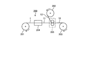
- FIG. 2 is the figure which showed typically an example of the manufacturing process of laminated body [A].
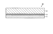
- FIG. 3 is a cross-sectional view schematically showing a laminate [A] obtained through the manufacturing process shown in FIG.
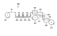
- FIG. 4 is a view schematically showing an example of a production process of producing a polarizing plate from the laminate [A] in the production methods of the first to third embodiments.
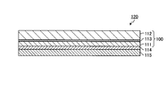
- FIG. 5 is a cross-sectional view schematically showing a polarizing plate obtained by the manufacturing method according to Embodiment 2 of the present invention.
- FIG. 1 is a cross-sectional view schematically showing a polarizing plate obtained by the manufacturing method according to Embodiment 1 of the present invention.
- FIG. 2 is the figure which showed typically an example of the manufacturing process of laminated body [A].
- FIG. 3 is a cross-sectional view schematically
- FIG. 6 is a cross-sectional view schematically showing a polarizing plate obtained by the manufacturing method according to Embodiment 3 of the present invention.
- FIG. 7 is a cross-sectional view schematically showing a display device obtained by the manufacturing method according to Embodiment 4 of the present invention.
- FIG. 8 is a cross-sectional view schematically showing a display device obtained by the manufacturing method according to Embodiment 5 of the present invention.
- FIG. 9 is a cross-sectional view schematically showing a display device obtained by the manufacturing method according to Embodiment 6 of the present invention.
- FIG. 10 is a cross-sectional view schematically showing a display device obtained by the manufacturing method according to Embodiment 7 of the present invention.
- a "long film” refers to a film having a length of 5 times or more, preferably 10 times or more of the width of the film, and specifically, It has a length that can be rolled up and stored or transported.
- the upper limit of the ratio of the length to the width of the film is not particularly limited, and may be, for example, 100,000 times or less.
- the Nz coefficient of the film is a value represented by [(nx-nz) / (nx-ny)] and can also be represented as [(Rth / Re) +0.5].
- nx is the refractive index in the slow axis direction in the plane of the film (the maximum refractive index in the plane)
- ny is the refractive index in the direction perpendicular to the slow axis in the plane of the film
- nz is the refractive index in the thickness direction of the film
- d is the thickness (nm) of the film.
- the measurement wavelength is 590 nm, which is a typical wavelength in the visible light range.
- Embodiment 1 is a cross-sectional view schematically showing a polarizing plate 100 obtained by the manufacturing method of the present embodiment.
- the base film 112 is laminated on one surface (upper surface in the figure) of the polarizer material film 111.
- 113 is an adhesive layer.
- the adhesive layer 113 is contained in the polarizing plate 100 obtained by the manufacturing method of this embodiment, the polarizing plate obtained by the manufacturing method of this invention may be the structure which does not contain an adhesive layer.
- a raw material film containing a material of a polarizer is stretched in one or more directions at a draw ratio X to obtain a polarizer material film (a), on a polarizer material film
- a step (c) of stretching the laminate [A] in one or more directions at a draw ratio Z are included in this order.
- the manufacturing method of the polarizing plate of this embodiment includes the step (d) of dyeing the polarizer material film with a dichroic substance after the step (b).
- FIG. 2 is schematic which shows typically an example of the manufacturing apparatus 200 which manufactures laminated body [A] obtained through a process (a) and a process (b).
- the manufacturing apparatus 200 includes feeding devices 201 and 202, a stretching device 204, a bonding device 205, and a winding device 203.
- the raw material film 1 fed out from the delivery device 201 is conveyed to the stretching device 204, and is stretched by the stretching device 204 to obtain the polarizer material film 11 (step (a)) ).
- the polarizer material film 11 thus obtained is conveyed to the bonding device 205, an adhesive is applied by the bonding device 205, and the substrate material film 12 fed out from the feeding device 202 is bonded.
- the laminate 10 is obtained (step (b)).
- the manufactured laminate 10 can be taken up by a take-up device 203, formed into a roll, and subjected to a further process.
- FIG. 4 is the schematic which showed typically an example of the manufacturing apparatus 300 which manufactures the polarizing plate 100 of this embodiment through a process (c) and a process (d).
- the manufacturing apparatus 300 includes delivery devices 301 and 307, processing devices 302 to 305, drying devices 306 and 309, a bonding device 308, and a winding device 310.
- the laminate 10 delivered from the delivery device 301 is conveyed to the processing devices 302 to 305, and dyed with a dichroic substance (step (d)), and the laminate is stretched. Processing such as treatment (step (c)) is performed. When the laminate after these treatments is dried by the drying device 306, the polarizing plate 100 is obtained. Each step will be described in detail below.
- Step (a) is a step of drawing a raw material film containing a material of a polarizer in one or more directions at a draw ratio X to obtain a polarizer material film.
- a raw film is a film for obtaining a polarizer material film, and means a film not subjected to a stretching process (an unstretched film containing a material of a polarizer).
- the raw film is not necessarily limited as long as the object of the present invention can be achieved, but a film of polyvinyl alcohol resin is preferable in terms of cost performance.
- the polyvinyl alcohol resin (hereinafter sometimes abbreviated as PVA) is not necessarily limited, but it is produced by saponifying polyvinyl acetate obtained by polymerizing vinyl acetate from the viewpoint of availability etc. It is preferred to use
- the degree of polymerization of PVA is preferably in the range of 500 to 8000, and the degree of saponification is preferably 90% by mole or more, from the viewpoint of excellent stretchability and polarization performance of the obtained film.
- the degree of polymerization is an average degree of polymerization measured in accordance with the description of JIS K 6726-1994
- the degree of saponification is a value measured in accordance with the description of JIS K 6726-1994.
- a more preferable range of the polymerization degree is 1000 to 6000, and more preferably 1500 to 4000.
- a more preferable range of the degree of saponification is 95 mol% or more, more preferably 99 mol% or more.
- PVA may be a copolymer or graft polymer of vinyl acetate and other copolymerizable monomers, as long as the effect of the present invention is not adversely affected.
- the method of producing a raw film film of PVA is not particularly limited, and it can be produced by a known method.
- a cast film is produced using a PVA solution in which PVA is dissolved in a solvent Method, wet film forming method (ejection in poor solvent), dry / wet film forming method, gel film forming method (PVA aqueous solution is once cooled and gelled, then the solvent is extracted and removed to obtain a raw film of PVA And any combination thereof, and any method such as a melt extrusion film forming method in which a solution of PVA containing a solvent is melted is used as a film forming solution.
- the casting film forming method and the melt extrusion film forming method are preferable because a raw film of PVA having high transparency and little coloring is obtained, and the melt extrusion film forming method is more preferable.
- the raw material film of PVA has a plasticizer such as polyhydric alcohol such as glycerin, which is added to the PVA in an amount of 0.01 to 100%, in order to improve mechanical physical properties and process passability during secondary processing. It is preferable to contain 1% by mass, and in order to improve handleability, film appearance, etc., a surfactant such as an anionic surfactant or a nonionic surfactant is 0.01 to 30% by mass with respect to PVA. It is preferable to contain.
- the raw film of PVA is an antioxidant, an ultraviolet light absorber, a lubricant, a pH adjuster, inorganic fine particles, a coloring agent, an antiseptic agent, an anti-mildew agent, and the like, as needed, as long as the effects of the present invention are not impaired. It may further contain other components other than the components, such as polymer compounds and water.
- the raw film of PVA can contain one or more of these other components.
- the thickness of the raw film is preferably 50 ⁇ m or less, more preferably 40 ⁇ m or less, still more preferably 30 ⁇ m or less, preferably 5 ⁇ m or more, more preferably 10 ⁇ m or more, still more preferably 15 ⁇ m or more.
- the thickness of the raw film is at least the lower limit of the above range, it is possible to obtain a polarizing plate having a sufficiently high degree of polarization, and when it is below the upper limit of the above range, the bending resistance of the polarizing plate is effective. Can be enhanced.
- a polarizer material film is a film (film for polarizers) for manufacturing a polarizer.
- the polarizer material film is obtained by stretching the raw film in one or more directions at a stretching ratio X.
- a polarizer material film is a (stretched) film containing a polarizer material.
- dry stretching As a method of extending
- stretching methods such as tenter stretching, float stretching, and hot roll stretching can be used.
- the dry stretching refers to a method of stretching treatment in which a high temperature (for example, 100 ° C. or higher) gas atmosphere is used. Air can be mentioned as a gas used in dry stretching.
- the conditions for the stretching when the raw film is stretched into a polarizer material film may be appropriately selected so as to obtain a desired polarizer material film.
- the mode of stretching when the raw film is stretched to be a polarizer material film may be any mode such as uniaxial stretching or biaxial stretching.
- the stretching direction is the longitudinal direction (direction parallel to the longitudinal direction of the long film), and the transverse direction (parallel to the width direction of the long film).
- Direction and an oblique direction (direction that is neither vertical nor horizontal).
- the relationship between the stretching direction in step (a) and the stretching direction in step (c) will be described in the description of step (c).
- the draw ratio X is preferably 2.0 or more, more preferably 2.5 or more, and one side is preferably 4.5 or less, more preferably 3.5 or less. That is, the polarizer material film is preferably a film drawn at a draw ratio X of 2.0 to 4.5, and a film drawn at a draw ratio X of 2.5 to 3.5. Is more preferred.
- the draw ratio X When the draw ratio X is equal to or less than the upper limit value of the above range, occurrence of breakage can be prevented when the raw film is stretched to form a polarizer material film.
- the draw ratio X When the draw ratio X is at least the lower limit of the above range, the draw ratio when drawing the laminate to obtain a polarizing plate can be lowered.
- stretching of an original film is performed by extending
- the stretching temperature at the time of dry-stretching the raw film to obtain a polarizer material film is preferably 100 ° C. or more, more preferably 110 ° C. or more, and preferably 150 ° C. or less, more preferably 140 ° C. or less .
- a polarizer material film of uniform film thickness can be obtained.
- the thickness T1 of the polarizer material film is preferably 40 ⁇ m or less, more preferably 30 ⁇ m or less, still more preferably 20 ⁇ m or less, preferably 3 ⁇ m or more, more preferably 5 ⁇ m or more.
- the thickness T1 of the polarizer material film is at least the lower limit of the above range, a polarizing plate having a sufficiently high degree of polarization can be obtained, and when it is at the upper limit of the above range, resistance to bending of the polarizing plate Can be effectively enhanced.
- the retardation Re1 in the in-plane direction of the polarizer material film is preferably 10 nm or more, more preferably 50 nm or more, still more preferably 100 nm or more, preferably 500 nm or less, more preferably 400 nm or less.
- the retardation Re1 in the in-plane direction of the polarizer material film is equal to or more than the lower limit value of the above range, the draw ratio when drawing the laminate to form a polarizing plate is suppressed low, and the base material after the drawing treatment The phase difference of can be kept low.
- the draw ratio can be lowered when the raw film is stretched to make a polarizer material film, It is possible to avoid problems such as the occurrence of wrinkles when the film is stretched alone.
- the Nz coefficient of the polarizer material film is preferably 0.95 or more, more preferably 0.99 or more, preferably 1.5 or less, more preferably 1.4 or less. When the Nz coefficient is in the above range, a polarizer having a sufficient degree of polarization can be obtained.
- the shape and dimensions of the polarizer material film can be appropriately adjusted according to the desired application. From the viewpoint of production efficiency, the polarizer material film is preferably a long film.
- the step (b) is a step of providing a base film on the polarizer material film to obtain a laminate [A].
- a polarizer material film and a base film can be bonded together with an adhesive agent, and the layer of a base film can be provided on a polarizer material film.
- an adhesive is used in the step (b), but in the production method of the present invention, the adhesive is an optional component. Applying an adhesive between the polarizer material film and the base film is preferable in that problems such as peeling between the two films can be prevented, but it is preferable to use a polarizer material film without using an adhesive. An adhesive may not be used if sufficient adhesion with the substrate film can be obtained.
- the adhesive for bonding the polarizer material film and the base film there is no particular limitation on the adhesive for bonding the polarizer material film and the base film, and for example, an acrylic adhesive, a urethane adhesive, a polyester adhesive, a polyvinyl alcohol adhesive, a polyolefin adhesive , Modified polyolefin adhesive, polyvinyl alkyl ether adhesive, rubber adhesive, vinyl chloride-vinyl acetate adhesive, SEBS (styrene-ethylene-butylene-styrene copolymer) adhesive, ethylene-styrene copolymer It is possible to use an ethylene-based adhesive such as coalescing, an acrylic-ester-based adhesive such as ethylene- (meth) acrylate copolymer, and an ethylene- (meth) acrylate copolymer.
- an acrylic adhesive such as coalescing
- an acrylic-ester-based adhesive such as ethylene- (meth) acrylate copolymer
- the surface of the base film to be attached to the polarizer material film may be subjected to an easy adhesion treatment such as corona treatment, saponification treatment, primer treatment, anchor coating treatment and the like.
- the base film is formed of a resin.
- resin which forms a substrate film.
- the base film is preferably a film composed of at least one selected from cycloolefin resin, amorphous polyester resin, polyolefin resin, and acrylic resin, and more preferably a film composed of cycloolefin resin.
- the cycloolefin resin forming the base film includes a cycloolefin polymer, and the cycloolefin polymer is a hydride of a ring opening polymer of a norbornene monomer, an addition copolymer of a norbornene monomer and an ⁇ -olefin And its hydride is preferable.
- a cycloolefin polymer an addition copolymer of a norbornene monomer and an ⁇ -olefin, and a hydrogenated product thereof are preferable from the viewpoint that a retardation is hardly expressed even when stretched.
- a cycloolefin type polymer is included,
- the cycloolefin type polymer is a polymer block [A] which has repeating unit [I] derived from an aromatic vinyl compound as a main component
- hydrogen Preferred are those made of hydrogenated block copolymer and the like.
- the substrate film preferably contains a plasticizer and / or a softener (either one or both of the plasticizer and the softener).
- a plasticizer and / or a softener either one or both of the plasticizer and the softener.
- plasticizer and the softener those which can be uniformly dissolved or dispersed in the resin forming the base film can be used.
- specific examples of the plasticizer and the softener include an ester-based plasticizer composed of a polyhydric alcohol and a monovalent carboxylic acid (hereinafter referred to as "polyhydric alcohol ester-based plasticizer"), and a polyvalent carboxylic acid and a monovalent Ester-based plasticizers such as ester-based plasticizers (hereinafter referred to as "polyvalent carboxylic acid ester-based plasticizers") consisting of alcohols, and phosphoric acid ester-based plasticizers, carbohydrate ester-based plasticizers, and other polymer softeners Can be mentioned.
- Ethylene glycol glycerol, and trimethylol propane are preferable.
- polyhydric alcohol ester-based plasticizers examples include ethylene glycol ester-based plasticizers, glycerin ester-based plasticizers, and other polyhydric alcohol ester-based plasticizers.
- polyvalent carboxylic acid ester-based plasticizers examples include dicarboxylic acid ester-based plasticizers and other polyvalent carboxylic acid ester-based plasticizers.
- phosphoric acid ester plasticizers include phosphoric acid alkyl esters such as triacetyl phosphate and tributyl phosphate; phosphoric acid cycloalkyl esters such as tricyclophenyl phosphate and cyclohexyl phosphate; triphenyl phosphate and tricresyl phosphate And phosphoric acid aryl esters.
- carbohydrate ester plasticizers include glucose pentaacetate, glucose pentapropionate, glucose pentabutyrate, sucrose octaacetate, sucrose octabenzoate and the like, among which sucrose octaacetate is more preferred. preferable.
- polymer softener examples include aliphatic hydrocarbon polymers, alicyclic hydrocarbon polymers, polyethyl acrylate, polymethyl methacrylate, methyl methacrylate and 2-hydroxyethyl methacrylate.
- Acrylic polymers such as polymers, copolymers of methyl methacrylate, methyl acrylate and 2-hydroxyethyl methacrylate; vinyl polymers such as polyvinyl isobutyl ether, poly N-vinyl pyrrolidone, etc.
- polystyrene poly 4- Styrene-based polymers such as hydroxystyrene; polyesters such as polybutylene succinate, polyethylene terephthalate and polyethylene naphthalate; polyethers such as polyethylene oxide and polypropylene oxide; polyamides, polyurethanes, polyureas and the like.
- aliphatic hydrocarbon polymers include low molecular weight polymers such as polyisobutylene, polybutene, poly-4-methylpentene, poly-1-octene, ethylene / ⁇ -olefin copolymer, and their hydrides; polyisoprene And low molecular weight products such as polyisoprene-butadiene copolymer and the hydrides thereof.
- the aliphatic hydrocarbon-based polymer preferably has a number average molecular weight of 300 to 5,000, from the viewpoint of easy dissolution or dispersion in the cycloolefin resin uniformly.
- polymer softeners may be homopolymers consisting of one type of repeating unit or copolymers having a plurality of repeating structures. In addition, two or more of the above polymers may be used in combination.
- plasticizer and / or softener As the plasticizer and / or softener, ester plasticizers, aliphatic hydrocarbon polymers and mixtures thereof are preferable.
- the proportion of the plasticizer and / or the softener (hereinafter also referred to as “plasticizer etc.”) in the base film is preferably 0.2 parts by weight or more, more preferably 100 parts by weight of the resin forming the base film. Is 0.5 parts by weight or more, still more preferably 1.0 part by weight or more, and preferably 40 parts by weight or less, more preferably 30 parts by weight or less.
- the substrate film may contain optional components in addition to the resin and the plasticizer.
- optional components include stabilizers such as antioxidants, ultraviolet light absorbers, light stabilizers, etc .; resin modifiers such as lubricants; colorants such as dyes and pigments; and antistatic agents.
- stabilizers such as antioxidants, ultraviolet light absorbers, light stabilizers, etc .
- resin modifiers such as lubricants
- colorants such as dyes and pigments
- antistatic agents can be used singly or in combination of two or more kinds, and the compounding amount thereof is appropriately selected as long as the object of the present invention is not impaired.
- the base film forms a film (hereinafter, also referred to as a “resin composition”) containing a component (a resin and a component to be added as necessary) for forming the base film into a film by any forming method. It can be manufactured by molding.
- melt extrusion molding is mentioned.
- the melt extrusion process is a method of melting a resin composition by an extruder, extruding into a film form from a T die attached to the extruder, bringing the extruded film into close contact with one or more cooling rolls, shaping and taking it out It can be done by Molding conditions in melt extrusion molding can be appropriately set in accordance with conditions such as the composition and molecular weight of the resin composition to be used.
- the thickness of a base film 10 micrometers or more are more preferable, 50 micrometers or less are preferable, and 30 micrometers or less are more preferable.
- the thickness of the substrate film is at least the lower limit of the above range, a laminate with a good bonding surface shape can be obtained, and by being below the upper limit of the above range, the laminate is stretched and polarized When a plate is obtained, the phase difference generated in the base film can be reduced.
- FIG. 3 is a cross-sectional view schematically showing a laminate [A] obtained through the step (b).
- the laminate 10 includes a stretched polarizer material film 11, an adhesive layer 13, and a base film 12.
- the laminate obtained through the step (b) may have a configuration not including the adhesive layer.
- it in order to distinguish the laminate [A] before the stretching treatment in the step of producing the polarizing plate and the laminate after the stretching treatment in the step of producing the polarizing plate, It may be called "stretched laminate".
- Step (c) is a step of drawing the laminate [A] obtained through the step (b) in one or more directions at a draw ratio Z.
- the method of stretching the laminate [A] is not particularly limited, but wet stretching is preferred.
- the draw ratio Z of the laminate [A] in the step (c) is 1.2 or more and 5.0 or less, and the above-mentioned formula (2) (1.2 ⁇ Z ⁇ 5.0) is satisfied.
- the draw ratio Z is preferably 1.5 or more, more preferably 2.0 or more, and preferably 4.5 or less, more preferably 4.0 or less.
- the product of the draw ratio X in step (a) and the draw ratio Z of the laminate in step (c) (hereinafter also referred to as "product of draw ratio") is 5.1 or more and 9.0 or less And satisfy the above-mentioned equation (3) (5.1 ⁇ X * Z ⁇ 9.0).
- the product (X * Z) of the draw ratio is preferably 5.5 or more, more preferably 6.0 or more, preferably 8.0 or less, more preferably 7.0 or less.
- the stretching temperature of the laminate [A] in the step (c) is not particularly limited.
- the specific stretching temperature is preferably 50 ° C. or more, more preferably 55 ° C. or more, particularly preferably 60 ° C. or more, preferably 160 ° C. or less.
- the temperature is more preferably 120 ° C. or less, particularly preferably 110 ° C. or less.
- the range of the stretching temperature is preferably either dry stretching or wet stretching, but is particularly preferred in the case of wet stretching.
- the stretching treatment of the laminate [A] in the step (c) is a treatment including stretching in at least one direction, may include only stretching in one direction, and includes stretching in two or more directions. It is also good.
- uniaxial stretching is preferable, free end uniaxial stretching is more preferable, and free end uniaxial stretching in the longitudinal direction is particularly preferable.
- the stretching is performed such that the stretching magnification of the stretching falls within the predetermined stretching magnification range.
- the stretching is performed such that the product of the stretching ratio of each stretching falls within the range of the predetermined stretching ratio.
- the stretching may be performed simultaneously or sequentially.
- the stretching direction in step (a) and the stretching direction in step (c) will be described.
- the stretching direction of the original film in the step (a) and the stretching direction of the laminate [A] in the step (c) are not particularly limited, but may be in the embodiments shown in the following (1) to (6) it can.
- the stretching direction in which the stretching ratio is larger is taken as the stretching direction in that step.
- ⁇ 1 and ⁇ 2 can include tolerances within the range that does not impair the effects of the present invention. For example, if .theta.1 and .theta.2 are 0.degree.
- the angle ⁇ 1 between the stretching direction in the step (a) and the width direction of the polarizer material film and the angle ⁇ 2 between the stretching direction in the step (c) and the width direction of the laminate [A] are as follows. be able to. (1) ⁇ 1 is 90 ° and ⁇ 2 is 90 °. (2) ⁇ 1 is 0 ° and ⁇ 2 is 0 °. (3) One of ⁇ 1 and ⁇ 2 is 90 °, and the other is 0 °. (4) ⁇ 1 is 90 °, ⁇ 2 (°) satisfies the following formula (4). ⁇ 2 ⁇ 90 (4) (5) ⁇ 1 (°) satisfies the following formula (5), and ⁇ 2 is 90 °. ⁇ 1 ⁇ 90 (5) (6) ⁇ 1 (°) and ⁇ 2 (°) satisfy the following formula (6) and the following formula (7). ⁇ 1 ⁇ 90 (6) ⁇ 2 ⁇ 90 (7)
- the above aspect (1) is preferable when the application of the polarizing plate is a polarizing plate for a liquid crystal display device, and (4) to (6) is preferable when the polarizing plate for an EL display device.
- the absolute value of the difference between ⁇ 1 and ⁇ 2 is preferably 50 or less, more preferably 30 or less, and still more preferably 10 or less.
- Step (d) is a step of dyeing the polarizer material film with a dichroic substance.
- the manufacturing method of this embodiment includes a step (d), it is an optional step in the manufacturing method of the present invention.
- the step (d) may be performed after the step (b) before the step (c).
- the dyeing of the polarizer material film may be performed on the polarizer material film before forming the laminate [A].
- the polarizer material film is stretched and optionally dyed, resulting in a film that can function as a polarizer.
- the dyeing may be performed by immersing the layer of the polarizer material film in a dyeing solution containing a dichroic substance.
- the staining solution may contain an iodide such as potassium iodide from the viewpoint of enhancing the staining efficiency.
- the dichroic substance is not particularly limited, but when the polarizing plate is used in a vehicle-mounted display, an organic dye is preferable as the dichroic substance.
- the polarizing plate of the present embodiment is obtained.
- the thickness T of the polarizer material film after passing through the step (c) (after stretching the laminate) is 20 ⁇ m or less.
- the thickness T of the polarizer material film is preferably 15 ⁇ m or less, more preferably 10 ⁇ m or less, preferably 1 ⁇ m or more, and more preferably 3 ⁇ m or more.
- the thickness T is not more than the upper limit value, the thickness of the polarizing plate can be reduced, and when the thickness T is not less than the lower limit value, a polarizing plate having a sufficiently high degree of polarization can be obtained.
- the phase difference Re in the in-plane direction of the base film after passing through the step (c) is preferably 20 nm or less.
- the retardation Re in the in-plane direction of the base film is more preferably 15 nm or less, still more preferably 10 nm or less, and preferably 0 nm or more.
- the retardation Re in the in-plane direction of the substrate film is in the above range, the substrate film is sufficiently low in the expression of retardation even after passing through the manufacturing process of the polarizing plate including the stretching treatment. can do.
- the polarizing plate is manufactured by stretching the laminate [A] including the polarizer material film stretched in advance, which is obtained in the step (a), the laminate [A] is stretched. It is possible to lower the draw ratio when manufacturing a polarizing plate. Thereby, since expression of a phase difference in the substrate film after stretching treatment of the laminate [A] can be suppressed, as the protective film of one surface of the polarizer material film as it is without peeling the substrate film. It can be used and waste material can be reduced.
- a base film can be used also as a protective film, and even if thickness is thin, the manufacturing method of the polarizing plate which can be manufactured efficiently can be provided.
- FIG. 5 is a cross-sectional view schematically showing a polarizing plate 120 obtained by the method of manufacturing a polarizing plate according to Embodiment 2 of the present invention.
- the base film 112 is laminated on one side (upper side in the figure) of the polarizer material film 111, and the other side of the polarizer material film 111 A protective film 115 is laminated on the lower side of the drawing.
- 113 and 114 are adhesive layers.
- the adhesive for bonding the protective film to the polarizer material film may be the same as the adhesive for bonding the base film to the polarizer material film.
- the manufacturing method of the polarizing plate 120 which concerns on this embodiment is a polarizer material of the extending
- the polarizing plate 100 of Embodiment 1 is conveyed to the laminating apparatus 308, and an adhesive is applied to the surface of the polarizer material film 111 on the side where the base film 112 is not laminated.
- the polarizing plate 120 provided with the protective film 115 is obtained by applying and bonding the protective film 115 delivered from the delivery device 307 (step (e1)).
- the manufactured polarizing plate 120 can be taken up by a take-up device 310, formed into a roll, and subjected to a further process.
- the polarizing plate obtained by the manufacturing method of the present embodiment is also obtained by stretching the laminate including the polarizer material film drawn in advance and obtained in the step (a). Have the same effects as in the first embodiment.
- Embodiment 3 Method of Manufacturing Polarizing Plate
- FIG. 6 is a cross-sectional view schematically showing a polarizing plate 130 obtained by the method of manufacturing a polarizing plate according to Embodiment 3 of the present invention.
- the base film 112 is laminated on one side (upper side in the figure) of the polarizer material film 111, and the other side of the polarizer material film 111
- the adhesive layer 116 is laminated on the lower side of the drawing.
- the manufacturing method of the polarizing plate of this embodiment is the polarizer material film of the stretched laminated body after the above-mentioned process (a), process (b), process (d) and process (c) and process (c)
- the process (e2) of providing an adhesive layer is included.
- the polarizing plate 130 according to the third embodiment is, for example, a film having a commercially available pressure-sensitive adhesive layer on the surface of the polarizing plate 100 of the first embodiment on which the base material film 112 of the polarizer material film 111 is not laminated.
- it can be obtained by transferring the pressure-sensitive adhesive layer from “Mustrak series” manufactured by Fujimori Kogyo, and forming the pressure-sensitive adhesive layer.
- the polarizing plate obtained by the manufacturing method of the present embodiment is also obtained by stretching the laminate including the polarizer material film drawn in advance and obtained in the step (a). Have the same effects as in the first embodiment.
- the polarizing plate obtained by the method for producing a polarizing plate of the present invention can be a material of a liquid crystal display.
- the liquid crystal display device comprises a light source, a light source side polarizing plate, a liquid crystal cell and a viewing side polarizing plate in this order, but the polarizing plate obtained by the present invention is either the light source side polarizing plate or the viewing side polarizing plate You may use.
- IPS in-plane switching
- VA vertical alignment
- MVA multidomain vertical alignment
- CPA continuous spin wheel alignment
- HAN hybrid alignment nematic
- TN twisted nematic
- STN super twisted nematic
- OBC optically compensated bend
- FIG. 1 a display device is manufactured by laminating the polarizing plate of the present invention as a light source side polarizing plate and a viewing side polarizing plate on a liquid crystal panel.
- FIG. 7 is a cross-sectional view schematically showing a liquid crystal display device 400 obtained by the manufacturing method according to the fourth embodiment.
- the liquid crystal display device 400 includes two substrates 410 and 420, a liquid crystal layer 430 positioned therebetween, and polarizing plates 100 and 100 disposed outside the two substrates 410 and 420, respectively.
- the two polarizing plates 100 are the polarizing plates of the first embodiment.
- the two polarizing plates 100 are laminated such that the base film 112 is disposed between the polarizer material film 111 and the liquid crystal layer 430, as shown in FIG. ing.
- the present embodiment it is possible to provide a method for producing a display device provided with the polarizing plate of the present invention, which can be used as a protective film and can be efficiently produced even if the thickness is thin. Can.
- FIG. 8 is a cross-sectional view schematically showing a liquid crystal display device 450 obtained by the manufacturing method according to Embodiment 5 of the present invention. As shown in FIG.
- the liquid crystal display device 450 includes two substrates 410 and 420, a liquid crystal layer 430 positioned therebetween, and a polarizing plate 120 disposed on the outer side (lower side in the figure) of the lower substrate 410.
- the polarizing plate 120 is the polarizing plate of the second embodiment. As shown in FIG. 8, the polarizing plate 120 is laminated such that the base film 112 is disposed between the polarizer material film 111 and the liquid crystal layer 430.
- the present embodiment it is possible to provide a method for producing a display device provided with the polarizing plate of the present invention, which can be used as a protective film and can be efficiently produced even if the thickness is thin. Can.
- the polarizing plate obtained by the method for producing a polarizing plate of the present invention can be a material of an EL display device.
- the organic EL display device comprises, in order from the light emitting side, a substrate, a transparent electrode, a light emitting layer and a metal electrode layer, but the polarizing plate obtained by the manufacturing method of the present invention is disposed on the light emitting side of the substrate. Ru.
- the EL display device has two substrates, a light emitting layer positioned between them, and a polarizing plate disposed outside one of the two substrates.
- the display device can be manufactured by laminating the polarizing plate of the present invention on an organic EL panel or an inorganic EL panel.
- FIG. 9 is a cross-sectional view schematically showing an organic EL display device 500 obtained by the manufacturing method according to Embodiment 6 of the present invention.
- the organic EL display device 500 includes two substrates 510 and 520, a light emitting layer 530 positioned between them, and a polarizing plate 100 disposed on the outer side (lower side in the drawing) of the lower substrate 510.
- the polarizing plate 100 is the polarizing plate of the first embodiment. As shown in FIG. 9, the polarizing plate 100 is laminated such that the base film 112 is disposed between the polarizer material film 111 and the light emitting layer 530.
- the present embodiment it is possible to provide a display device provided with the polarizing plate of the present invention, which can be used as a protective film and can be efficiently manufactured even if the thickness is thin.
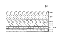
- FIG. 10 is a cross-sectional view schematically showing an organic EL display device 550 obtained by the manufacturing method according to Embodiment 7 of the present invention.
- the organic EL display device 550 has two substrates 510 and 520, a light emitting layer 530 positioned therebetween, and a polarizing plate 120 disposed on the outer side (lower side in the drawing) of the lower substrate 510.
- the polarizing plate 120 is the polarizing plate of the second embodiment. As shown in FIG. 10, the polarizing plate 120 is laminated such that the base film 112 is disposed between the polarizer material film 111 and the light emitting layer 530.
- the present embodiment it is possible to provide a display device provided with the polarizing plate of the present invention, which can be used as a protective film and can be efficiently manufactured even if the thickness is thin.
- the polarizing plate of the first embodiment is used as each of the light source side polarizing plate and the viewing side polarizing plate.
- any one of the polarizing plates is the polarizing plate of the second or third embodiment.
- two polarizing plates of Embodiment 2 or 3 may be used.
- the polarizing plate of the second embodiment is used as one of the light source side polarizing plate and the viewing side polarizing plate, but the polarizing plate of the first or third embodiment may be used.
- the polarizing plate of Embodiment 3 may be used for the inorganic EL display device.
- the hydrogenation rate of the block copolymer hydride was calculated by 1 H-NMR spectrum or GPC analysis.
- the region having a hydrogenation rate of 99% or less was calculated by measuring 1 H-NMR spectrum, and the region exceeding 99% was calculated by GPC analysis from the ratio of peak areas by a UV detector and an RI detector.
- Re and Rth were measured using a retardation measurement apparatus (product name “Axoscan” manufactured by Axometric Corporation) at a wavelength of 590 nm, and the Nz coefficient was determined based on them.
- the thickness before and after stretching of the raw film, the thickness of the base film, and the thickness of each layer contained in the polarizing plate were measured by the following methods. After cutting the polarizing plate using a microtome, its cross section was observed using a TEM. The size in the thickness direction was measured at five locations, and the average of the measured values was adopted as the thickness.
- Ts The single transmittance (Ts), the parallel transmittance (Tp) and the orthogonal transmittance (Tc) of the polarizing plate were measured using an ultraviolet-visible spectrophotometer (product name "V7100" manufactured by JASCO Corporation), and the degree of polarization (P) was determined by the following equation.
- Ts, Tp, and Tc are Y values which were measured by the visual field (C light source) of JIS Z 8701 and subjected to the visual sensitivity correction.
- Degree of polarization (P) (%) ⁇ (Tp-Tc) / (Tp + Tc) ⁇ 1/2 ⁇ 100 The measurement was performed so that the polarizer material film side of the polarizing plate was on the light incident side.
- Example 1 (1-1) Production of Substrate Film (1-1-1) Production of Polymer X
- 25 parts of styrene monomer is polymerized in the first step
- 30 parts of styrene monomer and 25 parts of isoprene monomer are polymerized in the second step
- 20 parts of styrene monomer is polymerized in the third step to obtain a block copolymer [D1], and then the block copolymer is obtained.
- the coalesced was hydrogenated to synthesize block copolymer hydride [E1].
- Mw of the block copolymer hydride [E1] was 84,500, Mw / Mn was 1.20, and the hydrogenation rate of the main chain and the aromatic ring was almost 100%.
- 100 parts of block copolymer hydride [E1], pentaerythrityl tetrakis [3- (3,5-di-t-butyl-4-hydroxyphenyl) propionate] (manufactured by Matsubara Sangyo Co., Ltd.) as an antioxidant
- 0.1 parts of the name "Songnox 1010” was melt-kneaded and blended, it was pelletized to obtain a polymer X for molding.
- the polymer X produced in (1-1-1) was supplied to a hot melt extruded film molding machine equipped with a T-die.
- the polymer X was formed into a film by extruding the polymer X from the T die and winding it on a roll at a take-up speed of 4 m / min. Thereby, the elongate base film A (20 micrometers in thickness) which consists of the polymer X was obtained.
- Step (a) As a raw film, an unstretched polyvinyl alcohol film (average polymerization degree about 2400, saponification degree 99.9 mol%, thickness 20 ⁇ m, hereinafter referred to as “PVA 20”) was used. The raw film was dry stretched at a stretching temperature of 130 ° C. in the longitudinal direction at a stretching ratio of 3.0 using a longitudinal uniaxial stretching machine to obtain a polarizer material film.
- the thickness T1 of the polarizer material film was 12 ⁇ m, the in-plane retardation Re1 was 345 nm, and the Nz coefficient was 1.0.
- Step (b) 100 parts by weight of water, 3 parts by weight of a polyvinyl alcohol-based adhesive ("Z-200" manufactured by Nippon Synthetic Chemical Co., Ltd.), and 0.3 parts by weight of a crosslinking agent ("SPM-01” manufactured by Japan Synthetic Chemical Co., Ltd.)
- the adhesive composition was obtained.
- One surface of the substrate film A obtained in (1-1-2) was subjected to corona treatment, the adhesive composition was coated thereon, and it was bonded to one surface of the polarizer material film. In this state, the adhesive composition was dried by heating at 70 ° C. for 5 minutes.
- a laminate [A] having a layer structure of “polarizer material film” / “adhesive layer” / “base film A” was obtained.
- the thickness of the adhesive layer was 1 ⁇ m.
- the base film A in the said laminated body [A] is an unstretched film.
- the bonding surface state of the obtained laminate [A] was evaluated. The results are shown in Table 1.
- step (1-4) Production of polarizing plate (wet process) (step (d), step (c))
- the following operation was performed while continuously conveying the laminate [A] obtained in (1-3) in the longitudinal direction via a guide roll.
- stretches the laminated body after a dyeing process were performed.
- the laminate after the first stretching was subjected to a second stretching in a 65 ° C. acid bath containing boric acid and potassium iodide.
- the total draw ratio represented by the product of the draw ratio in the first drawing process and the draw ratio in the second drawing process was set to be 2.0.
- the stretched laminate after the second stretching treatment was dried at 70 ° C. for 5 minutes in a drier to obtain a polarizing plate. Thickness of polarizing plate (total thickness), thickness of substrate film (substrate thickness) and retardation Re (substrate Re) of polarizing plate, thickness T of polarizer material film, and polarization at single transmittance 42.8%
- the degree (%) was measured, and is shown in Table 1 together with the evaluation result of the stretchability.
- Example 2 A polarizing plate was manufactured in the same manner as in Example 1 except that the polarizer material film obtained in (2-2) below was used instead of the polarizer material film obtained in (1-2). The evaluation was carried out in the same manner as in Example 1, and the results are shown in Table 1.
- An unstretched polyvinyl alcohol film (average polymerization degree about 2400, saponification degree 99.9 mol%, thickness 30 ⁇ m, hereinafter also referred to as “PVA 30”) is used as a raw film. It was.
- the raw film (PVA 30) was stretched at a stretching temperature of 130 ° C. in the longitudinal direction at a stretching ratio of 3.0 using a longitudinal uniaxial stretching machine to obtain a polarizer material film.
- the thickness T1 of the polarizer material film was 17 ⁇ m, and Re1 was 520 nm.
- Example 3 Instead of the polarizer material film obtained in (1-2), a laminate [A] was produced using the polarizer material film obtained in (3-2) below, and (1-4 The polarizing plate was manufactured in the same manner as in Example 1 except that the drawing ratio was changed to thereby change the total drawing ratio to 3.0, and the evaluation was carried out in the same manner as in Example 1. Shown in 1.
- Example 4 Using the polarizer material film obtained in the following (4-2) instead of the polarizer material film obtained in (1-2), the following method (4-3) and (4-4) A polarizing plate was produced by the method of 1. and evaluated in the same manner as in Example 1. The results are shown in Table 1.
- Example 5 Using the polarizer material film obtained in the following (5-2) instead of the polarizer material film obtained in (1-2), the following method (5-3) and (5-4) A polarizing plate was produced by the method of 1. and evaluated in the same manner as in Example 1. The results are shown in Table 1.
- Example 6 Using the polarizer material film obtained in the following (6-2) instead of the polarizer material film obtained in (1-2), the following method (6-3) and (6-4) A polarizing plate was produced by the method of 1. and evaluated in the same manner as in Example 1. The results are shown in Table 1.
- Example 7 Using the laminate [A] obtained in (1-3), a polarizing plate was produced by the method of (7-4) below, evaluated in the same manner as in Example 1 and the results are shown in Table 2 .
- Example 8 A polarizing plate is manufactured in the same manner as Example 1, except that the polarizer material film obtained in (8-2) below is used instead of the polarizer material film obtained in (1-2) The evaluation was performed in the same manner as in Example 1. The results are shown in Table 2.
- the thickness T1 of the polarizer material film was 7 ⁇ m, and Re1 was 310 nm.
- Example 9 Using the polarizer material film obtained in the following (9-2) instead of the polarizer material film obtained in (1-2), the following method (9-3) and (9-4) A polarizing plate was produced by the method of 1. and evaluated in the same manner as in Example 1. The results are shown in Table 2.
- Example 10 (10-1) Production of Substrate Film B The same as (1-1) except that the conditions for extruding the polymer X in (1-1-2) were changed to obtain a thickness of 25 ⁇ m. Thus, a long base film B (thickness 25 ⁇ m) made of the polymer X was obtained.
- Laminate [A] The substrate film obtained in (10-1) in place of the substrate film A using the polarizer material film obtained in (11-2) instead of the polarizer material film obtained in (1-2) A laminate [A] having a layer structure of “polarizer material film” / “adhesive layer” / “base film B” was obtained in the same manner as (1-3) except that B was used.
- Example 12 (12-2) Production of Polarizer Material Film A polarizer material film was obtained in the same manner as (1-2) except that the raw film (PVA 20) was drawn at a draw ratio of 3.5.
- the thickness T1 of the polarizer material film was 11 ⁇ m, and Re1 was 340 nm.
- Laminate [A] A substrate film B obtained in (10-1) in place of the substrate film A using the polarizer material film obtained in (12-2) instead of the polarizer material film obtained in (1-2)
- a laminate [A] having a layer structure of “polarizer material film” / “adhesive layer” / “base film B” was obtained in the same manner as (1-3) except using.
- Laminate [A] A substrate film B obtained in (10-1) in place of the substrate film A using the polarizer material film obtained in (13-2) instead of the polarizer material film obtained in (1-2) A laminate [A] having a layer structure of “polarizer material film” / “adhesive layer” / “base film B” was obtained in the same manner as (1-3) except using.
- Example 14 A polarizing plate was manufactured in the same manner as in Example 1, except that the base film D obtained in (14-1) below was used instead of the base film A obtained in (1-1). The evaluation was carried out in the same manner as in Example 1, and the results are shown in Table 3.
- Example 15 A polarizing plate is manufactured by the method of the following (15-4) using the laminate [A] obtained in the following (15-3), evaluated in the same manner as in Example 1, and the results are shown in Table 3. Indicated.
- Example 16 A polarizing plate was manufactured by the following method (16-4) using the laminate [A] obtained in (16-3), and evaluated in the same manner as in Example 1. The results are shown in Table 3 .
- the laminate [A] obtained in (16-3) is dyed by immersing it in a dyeing solution containing CI Direct Red 81, sodium tripolyphosphate, and anhydrous sodium sulfate. Done and dried in the dryer at 70 ° C. for 5 minutes.
- the processed product of the obtained laminate [A] was stretched at a stretching temperature of 110 ° C. in the longitudinal direction at a stretching ratio of 2.0 using a longitudinal uniaxial stretching machine. Subsequently, the resultant was dipped in an acid bath containing boric acid and crosslinked, and dried at 70 ° C. for 5 minutes to obtain a polarizing plate.
- the thickness of the base film was 18 ⁇ m, and the retardation was 1 nm.
- the thickness of the polarizer material film of the stretched laminate was 8 ⁇ m.
- Example 17 A polarizing plate was manufactured by the following method, evaluated in the same manner as in Example 1, and the results are shown in Table 3.
- Example 18 A polarizing plate was manufactured by the following method (18-4) using the laminate [A] obtained in (18-3), and evaluated in the same manner as in Example 1. The results are shown in Table 3 .
- Comparative Example 2 (C2-2) Production of Polarizer Material Film A polarizer material film was obtained in the same manner as (1-2) except that the stretching ratio was changed to 5.7.
- the thickness T1 of the polarizer material film was 8 ⁇ m, and Re1 was 320 nm.
- a polyvinyl alcohol (PVA) layer was formed on the surface of a base film C4 according to the following procedure to produce a laminate [A].
- a base film C4 a base film (200 ⁇ m thick) of a continuous web of amorphous polyethylene terephthalate (amorphous PET, glass transition temperature: 75 ° C.) obtained by copolymerizing 6 mol% of isophthalic acid was used.
- the PVA aqueous solution is applied to one surface of the base film C4 and dried at a temperature of 50 to 60 ° C. to form a PVA layer on the surface of the base film C4 to form a layer structure of PVA layer / base film C4.
- a laminate [A] having the In this comparative example, the PVA layer is formed by applying and drying a PVA aqueous solution, but the thickness and the phase difference in the in-plane direction of the layer can be determined by comparing “thickness T1 after stretching” and “position after stretching”. Each is described in the column of "Retardation Re1".
- (C4-4) Production of Polarizing Plate The laminate [A] obtained in (C4-3) was subjected to a stretching apparatus installed in an oven set to a stretching temperature environment of 130 ° C., and the stretching ratio was 1.8 times. The free end uniaxial stretching was performed so as to be (1st stretching processing).
- the laminate [A] after the first stretching treatment was subjected to a dyeing treatment in which the laminate [A] was immersed in a dyeing solution containing iodine and potassium iodide.
- the laminate [A] after the dyeing process is subjected to a stretching apparatus installed in a processing apparatus set to a boric acid aqueous solution containing boric acid and potassium iodide at 65 ° C., and the draw ratio becomes 3.3 times
- the stretching process was performed on the free end uniaxially (second stretching process).
- the stretching direction was the longitudinal direction in both the first stretching process and the second stretching process.
- the laminate [A] after the second stretching treatment is taken out from the aqueous boric acid solution, and the boric acid attached to the surface of the 3 ⁇ m-thick PVA layer formed on the amorphous PET substrate is washed with an aqueous potassium iodide solution
- the sheet was dried by a drying process with warm air at 60 ° C. to obtain a polarizing plate.
- the thickness of the base film and the retardation Re (base Re) of the polarizing plate, the thickness T of the PVA layer, the overall thickness, and the degree of polarization were measured, and are shown in Table 4 together with the evaluation results of stretchability.
Landscapes
- Physics & Mathematics (AREA)
- General Physics & Mathematics (AREA)
- Engineering & Computer Science (AREA)
- Optics & Photonics (AREA)
- Nonlinear Science (AREA)
- Theoretical Computer Science (AREA)
- Mechanical Engineering (AREA)
- Chemical & Material Sciences (AREA)
- Crystallography & Structural Chemistry (AREA)
- Mathematical Physics (AREA)
- Manufacturing & Machinery (AREA)
- Polarising Elements (AREA)
- Devices For Indicating Variable Information By Combining Individual Elements (AREA)
- Liquid Crystal (AREA)
- Shaping By String And By Release Of Stress In Plastics And The Like (AREA)
Abstract
偏光板の製造方法であって、偏光子の材料を含む原反フィルムを一以上の方向に延伸倍率Xで延伸して偏光子材料フィルムを得る工程(a)、前記偏光子材料フィルム上に基材フィルムを設けて積層体[A]を得る工程(b)、前記積層体[A]を一以上の方向に延伸倍率Zで延伸する工程(c)をこの順で含み、Xが1.5以上5.5以下、Zが1.2以上5.0以下、X*Zが5.1以上9.0以下であり、工程(c)を経た後の偏光子材料フィルムの厚みTが20μm以下である、偏光板の製造方法。
Description
本発明は、偏光板の製造方法及び表示装置の製造方法に関する。
液晶表示装置及び有機エレクトロルミネッセンス(EL)表示装置等の表示装置としては、従来から、表示面積が大きく、重量が軽く、且つ厚みが薄いものが求められている。そのため、表示装置を構成するパネルも、従来から薄いものが求められている。
表示装置には、偏光子及び偏光子を保護する保護フィルムを備える偏光板が一般的に用いられる。厚みの薄い表示装置を構成するために、偏光板も、より薄いものが求められている。特に、偏光子として一般的に用いられるポリビニルアルコール等の材料は、表示装置の使用環境において収縮することがあるため、薄く面積が大きい表示装置においては、そのような収縮による反りが問題となりうる。したがって、厚み10μm以下といった薄い偏光子を採用することにより、偏光子の厚みの低減自体による表示装置の厚みの低減に加え、前述のような反りの発生の低減も期待できる。
ところが、従来の製造方法により、そのような厚みの薄いポリビニルアルコールの偏光子を製造しようとした場合、偏光子の溶断が頻発する。このような、偏光子の溶断を防ぎ、且つ薄い偏光子を含む偏光板を製造する方法として、いくつかの方法が提案されている。例えば特許文献1では、未延伸高密度ポリエチレン製の基材フィルムに未延伸ポリビニルアルコール系フィルムを貼りつけて積層体とし、当該積層体を延伸処理した後に、基材フィルムを剥離して、ポリビニルアルコール系フィルムを得る方法が提案されている。
また、特許文献2では、非晶質エステル系熱可塑性樹脂基材に、ポリビニルアルコール系樹脂を含む水溶液を塗布することによりポリビニルアルコール系樹脂層を製膜して積層体とし、当該積層体を延伸処理した後、二色性物質を配向させて着色積層体とし、当該着色積層体を延伸処理して光学フィルムを得る方法が提案されている。
また、特許文献2では、非晶質エステル系熱可塑性樹脂基材に、ポリビニルアルコール系樹脂を含む水溶液を塗布することによりポリビニルアルコール系樹脂層を製膜して積層体とし、当該積層体を延伸処理した後、二色性物質を配向させて着色積層体とし、当該着色積層体を延伸処理して光学フィルムを得る方法が提案されている。
特許文献1および2に記載の方法により薄い偏光板を製造する場合、積層体を高い延伸倍率で延伸することに起因して、延伸処理後の基材フィルムにおいて位相差が発生することがある。そのような場合に、基材フィルムをそのまま偏光板保護フィルムとして使用することは難しく、剥離して廃棄することになるため、無駄になる材料が発生する。さらに、偏光板を保護するための保護フィルムを別途用意して、偏光板に貼り付ける作業が生じうる。
また、十分な幅の薄型の偏光板を得るには、幅寸法のきわめて広い基材フィルムを用意して、偏光子の材料(例えばポリビニルアルコール材料)を塗布又は貼り付けることが考えられるが、基材フィルムの幅寸法が大きくなりすぎると、生産が困難であるという問題がある。
従って、本発明は、基材フィルムを保護フィルムとしても用いることができ、厚みが薄くても効率的に製造することができる偏光板の製造方法、及び前記の偏光板を備えた表示装置の製造方法を提供することを目的とする。
上記課題を解決するために検討を行った結果、本発明者は、所定の延伸倍率で延伸した偏光子材料フィルムを含む積層体を、所定の延伸倍率で延伸することにより、上記課題を解決しうることを見出し、本発明を完成した。
従って、本発明によれば、下記〔1〕~〔22〕が提供される。
〔1〕 偏光板の製造方法であって、
偏光子の材料を含む原反フィルムを一以上の方向に延伸倍率Xで延伸して偏光子材料フィルムを得る工程(a)、
前記偏光子材料フィルム上に基材フィルムを設けて積層体[A]を得る工程(b)、
前記積層体[A]を一以上の方向に延伸倍率Zで延伸する工程(c)をこの順で含み、
XおよびZが下記式(1)~(3)の関係を満たし、
工程(c)を経た後の偏光子材料フィルムの厚みTが20μm以下である、偏光板の製造方法。
1.5≦X≦5.5…(1)
1.2≦Z≦5.0…(2)
5.1≦X*Z≦9.0…(3)
〔2〕 前記工程(b)の後に、前記偏光子材料フィルムを二色性物質で染色する工程(d)を含む、〔1〕に記載の偏光板の製造方法。
〔3〕 前記工程(c)を、50℃~160℃の温度条件下において行う、〔1〕または〔2〕に記載の偏光板の製造方法。
〔4〕 前記偏光子材料フィルムが、ポリビニルアルコール樹脂からなる、〔1〕~〔3〕のいずれか1項に記載の偏光板の製造方法。
〔5〕 前記工程(c)を経た後の基材フィルムの面内方向の位相差が20nm以下である、〔1〕~〔4〕のいずれか一項に記載の偏光板の製造方法。
〔6〕 前記工程(c)の後に、前記積層体[A]の偏光子材料フィルムに、直接または接着剤を介して保護フィルムを貼合する工程(e1)、または前記偏光子材料フィルムに粘着剤層を設ける工程(e2)を含む、〔1〕~〔5〕のいずれか一項に記載の偏光板の製造方法。
〔7〕 前記基材フィルム層が、シクロオレフィン樹脂、非晶質ポリエステル樹脂、ポリオレフィン樹脂、アクリル樹脂から選ばれる少なくとも1種からなるフィルムである、〔1〕~〔6〕のいずれか一項に記載の偏光板の製造方法。
〔8〕 前記基材フィルムがシクロオレフィン樹脂からなるフィルムであり、
前記シクロオレフィン樹脂が、シクロオレフィン系ポリマーを含み、
前記シクロオレフィン系ポリマーが、ノルボルネン系モノマーの開環重合体の水素化物、ノルボルネン系モノマーとα-オレフィンとの付加共重合体及びその水素化物から選ばれる少なくとも1種からなる、〔1〕~〔7〕のいずれか一項に記載の偏光板の製造方法。
〔9〕 前記基材フィルムがシクロオレフィン樹脂からなるフィルムであり、
前記シクロオレフィン樹脂が、シクロオレフィン系ポリマーを含み、
前記シクロオレフィン系ポリマーが、芳香族ビニル化合物由来の繰り返し単位[I]を主成分とする重合体ブロック[A]と、
芳香族ビニル化合物由来の繰り返し単位[I]及び鎖状共役ジエン化合物由来の繰り返し単位[II]を主成分とする重合体ブロック[B]又は、
鎖状共役ジエン化合物由来の繰り返し単位[II]を主成分とする重合体ブロック[C]と、
からなるブロック共重合体[D]を、
水素化したブロック共重合体水素化物からなる、〔1〕~〔7〕のいずれか一項に記載の偏光板の製造方法。
〔10〕 前記基材フィルム層が、可塑剤及び/又は軟化剤を含有する、〔1〕~〔9〕のいずれか一項に記載の偏光板の製造方法。
〔11〕 前記可塑剤及び/又は軟化剤が、エステル系可塑剤、脂肪族炭化水素ポリマー又はこれらの混合物である、〔10〕に記載の偏光板の製造方法。
〔12〕 前記工程(a)の延伸方向と偏光子材料フィルムの幅方向とのなす角θ1が90°で、前記工程(c)の延伸方向と積層体[A]の幅方向とのなす角θ2が90°である、〔1〕~〔11〕のいずれか一項に記載の偏光板の製造方法。
〔13〕 前記工程(a)の延伸方向と偏光子材料フィルムの幅方向とのなす角θ1が0°で、前記工程(c)の延伸方向と積層体[A]の幅方向とのなす角θ2が0°である、〔1〕~〔11〕のいずれか一項に記載の偏光板の製造方法。
〔14〕 前記工程(a)の延伸方向と偏光子材料フィルムの幅方向とのなす角θ1、及び、前記工程(c)の延伸方向と積層体[A]の幅方向とのなす角θ2のうち、いずれか一方が90°で、他方が0°である、〔1〕~〔11〕のいずれか一項に記載の偏光板の製造方法。
〔15〕 前記工程(a)の延伸方向と偏光子材料フィルムの幅方向とのなす角θ1が90°で、前記工程(c)の延伸方向と積層体[A]の幅方向とのなす角θ2(°)が下記式(4)を満たす、〔1〕~〔11〕のいずれか一項に記載の偏光板の製造方法。
θ2≠90…(4)
〔16〕 前記工程(a)の延伸方向と偏光子材料フィルムの幅方向とのなす角θ1(°)が下記式(5)を満たし、
前記工程(c)の延伸方向と積層体[A]の幅方向とのなす角θ2が90°である、〔1〕~〔11〕のいずれか一項に記載の偏光板の製造方法。
θ1≠90…(5)
〔17〕 前記工程(a)の延伸方向と偏光子材料フィルムの幅方向とのなす角θ1(°)、及び前記工程(c)の延伸方向と積層体[A]の幅方向とのなす角θ2(°)が、下記式(6)および下記式(7)を満たす、〔1〕~〔11〕のいずれか一項に記載の偏光板の製造方法。
θ1≠90…(6)
θ2≠90…(7)
〔18〕 前記θ1と前記θ2の差の絶対値が50以下である、〔15〕~〔17〕のいずれか一項に記載の偏光板の製造方法。
〔19〕 前記二色性物質が有機染料である、〔2〕~〔18〕のいずれか一項に記載の偏光板の製造方法。
〔20〕 〔12〕~〔14〕のいずれか一項に記載の製造方法により得られた偏光板を液晶パネルに積層する、表示装置の製造方法。
〔21〕 〔15〕~〔17〕のいずれか一項に記載の製造方法により得られた偏光板を有機ELパネルまたは無機ELパネルに積層する、表示装置の製造方法。
〔22〕 〔19〕に記載の製造方法により得られた偏光板を車載用表示パネルに積層する、表示装置の製造方法。
従って、本発明によれば、下記〔1〕~〔22〕が提供される。
〔1〕 偏光板の製造方法であって、
偏光子の材料を含む原反フィルムを一以上の方向に延伸倍率Xで延伸して偏光子材料フィルムを得る工程(a)、
前記偏光子材料フィルム上に基材フィルムを設けて積層体[A]を得る工程(b)、
前記積層体[A]を一以上の方向に延伸倍率Zで延伸する工程(c)をこの順で含み、
XおよびZが下記式(1)~(3)の関係を満たし、
工程(c)を経た後の偏光子材料フィルムの厚みTが20μm以下である、偏光板の製造方法。
1.5≦X≦5.5…(1)
1.2≦Z≦5.0…(2)
5.1≦X*Z≦9.0…(3)
〔2〕 前記工程(b)の後に、前記偏光子材料フィルムを二色性物質で染色する工程(d)を含む、〔1〕に記載の偏光板の製造方法。
〔3〕 前記工程(c)を、50℃~160℃の温度条件下において行う、〔1〕または〔2〕に記載の偏光板の製造方法。
〔4〕 前記偏光子材料フィルムが、ポリビニルアルコール樹脂からなる、〔1〕~〔3〕のいずれか1項に記載の偏光板の製造方法。
〔5〕 前記工程(c)を経た後の基材フィルムの面内方向の位相差が20nm以下である、〔1〕~〔4〕のいずれか一項に記載の偏光板の製造方法。
〔6〕 前記工程(c)の後に、前記積層体[A]の偏光子材料フィルムに、直接または接着剤を介して保護フィルムを貼合する工程(e1)、または前記偏光子材料フィルムに粘着剤層を設ける工程(e2)を含む、〔1〕~〔5〕のいずれか一項に記載の偏光板の製造方法。
〔7〕 前記基材フィルム層が、シクロオレフィン樹脂、非晶質ポリエステル樹脂、ポリオレフィン樹脂、アクリル樹脂から選ばれる少なくとも1種からなるフィルムである、〔1〕~〔6〕のいずれか一項に記載の偏光板の製造方法。
〔8〕 前記基材フィルムがシクロオレフィン樹脂からなるフィルムであり、
前記シクロオレフィン樹脂が、シクロオレフィン系ポリマーを含み、
前記シクロオレフィン系ポリマーが、ノルボルネン系モノマーの開環重合体の水素化物、ノルボルネン系モノマーとα-オレフィンとの付加共重合体及びその水素化物から選ばれる少なくとも1種からなる、〔1〕~〔7〕のいずれか一項に記載の偏光板の製造方法。
〔9〕 前記基材フィルムがシクロオレフィン樹脂からなるフィルムであり、
前記シクロオレフィン樹脂が、シクロオレフィン系ポリマーを含み、
前記シクロオレフィン系ポリマーが、芳香族ビニル化合物由来の繰り返し単位[I]を主成分とする重合体ブロック[A]と、
芳香族ビニル化合物由来の繰り返し単位[I]及び鎖状共役ジエン化合物由来の繰り返し単位[II]を主成分とする重合体ブロック[B]又は、
鎖状共役ジエン化合物由来の繰り返し単位[II]を主成分とする重合体ブロック[C]と、
からなるブロック共重合体[D]を、
水素化したブロック共重合体水素化物からなる、〔1〕~〔7〕のいずれか一項に記載の偏光板の製造方法。
〔10〕 前記基材フィルム層が、可塑剤及び/又は軟化剤を含有する、〔1〕~〔9〕のいずれか一項に記載の偏光板の製造方法。
〔11〕 前記可塑剤及び/又は軟化剤が、エステル系可塑剤、脂肪族炭化水素ポリマー又はこれらの混合物である、〔10〕に記載の偏光板の製造方法。
〔12〕 前記工程(a)の延伸方向と偏光子材料フィルムの幅方向とのなす角θ1が90°で、前記工程(c)の延伸方向と積層体[A]の幅方向とのなす角θ2が90°である、〔1〕~〔11〕のいずれか一項に記載の偏光板の製造方法。
〔13〕 前記工程(a)の延伸方向と偏光子材料フィルムの幅方向とのなす角θ1が0°で、前記工程(c)の延伸方向と積層体[A]の幅方向とのなす角θ2が0°である、〔1〕~〔11〕のいずれか一項に記載の偏光板の製造方法。
〔14〕 前記工程(a)の延伸方向と偏光子材料フィルムの幅方向とのなす角θ1、及び、前記工程(c)の延伸方向と積層体[A]の幅方向とのなす角θ2のうち、いずれか一方が90°で、他方が0°である、〔1〕~〔11〕のいずれか一項に記載の偏光板の製造方法。
〔15〕 前記工程(a)の延伸方向と偏光子材料フィルムの幅方向とのなす角θ1が90°で、前記工程(c)の延伸方向と積層体[A]の幅方向とのなす角θ2(°)が下記式(4)を満たす、〔1〕~〔11〕のいずれか一項に記載の偏光板の製造方法。
θ2≠90…(4)
〔16〕 前記工程(a)の延伸方向と偏光子材料フィルムの幅方向とのなす角θ1(°)が下記式(5)を満たし、
前記工程(c)の延伸方向と積層体[A]の幅方向とのなす角θ2が90°である、〔1〕~〔11〕のいずれか一項に記載の偏光板の製造方法。
θ1≠90…(5)
〔17〕 前記工程(a)の延伸方向と偏光子材料フィルムの幅方向とのなす角θ1(°)、及び前記工程(c)の延伸方向と積層体[A]の幅方向とのなす角θ2(°)が、下記式(6)および下記式(7)を満たす、〔1〕~〔11〕のいずれか一項に記載の偏光板の製造方法。
θ1≠90…(6)
θ2≠90…(7)
〔18〕 前記θ1と前記θ2の差の絶対値が50以下である、〔15〕~〔17〕のいずれか一項に記載の偏光板の製造方法。
〔19〕 前記二色性物質が有機染料である、〔2〕~〔18〕のいずれか一項に記載の偏光板の製造方法。
〔20〕 〔12〕~〔14〕のいずれか一項に記載の製造方法により得られた偏光板を液晶パネルに積層する、表示装置の製造方法。
〔21〕 〔15〕~〔17〕のいずれか一項に記載の製造方法により得られた偏光板を有機ELパネルまたは無機ELパネルに積層する、表示装置の製造方法。
〔22〕 〔19〕に記載の製造方法により得られた偏光板を車載用表示パネルに積層する、表示装置の製造方法。
本発明によれば、積層体を延伸する工程を経た後でも基材フィルムに発現する位相差を小さくしうるので、基材フィルムを保護フィルムとしても用いることができ、厚みが薄くても効率的に製造することができる偏光板の製造方法、及び前記の偏光板を備えた表示装置の製造方法を提供することができる。
以下、本発明について実施形態及び例示物を示して詳細に説明する。ただし、本発明は以下に説明する実施形態及び例示物に限定されるものではなく、本発明の請求の範囲及びその均等の範囲を逸脱しない範囲において任意に変更して実施してもよい。
本願において、「長尺状」のフィルムとは、フィルムの幅に対して、5倍以上の長さを有するものをいい、好ましくは10倍若しくはそれ以上の長さを有し、具体的にはロール状に巻き取られて保管又は運搬される程度の長さを有するものをいう。フィルムの幅に対する長さの割合の上限は、特に限定されないが、例えば100,000倍以下としうる。
本願において、フィルムの面内方向の位相差Re及び厚み方向の位相差Rthは、式Re=(nx-ny)×d、及びRth=[{(nx+ny)/2}-nz]×dに従って算出する。またフィルムのNz係数は、[(nx-nz)/(nx-ny)]で表される値であり、[(Rth/Re)+0.5]とも表しうる。ここで、nxは、フィルムの面内の遅相軸方向の屈折率(面内の最大屈折率)であり、nyは、フィルムの面内の遅相軸に垂直な方向の屈折率であり、nzは、フィルムの厚み方向の屈折率であり、dは、フィルムの厚み(nm)である。測定波長は、別に断らない限り、可視光領域の代表的な波長である590nmとする。
〔実施形態1:偏光板の製造方法〕
〔1.偏光板の製造方法の概要〕
本発明の実施形態1に係る偏光板の製造方法について図1~4を参照しつつ説明する。
図1は本実施形態の製造方法により得られる偏光板100を模式的に示した断面図である。偏光板100においては、図1に示すように、偏光子材料フィルム111の一方の面(図示上側面)の上に基材フィルム112が積層されている。図1中、113は接着剤層である。本実施形態の製造方法により得られる偏光板100には接着剤層113が含まれるが、本発明の製造方法により得られる偏光板は接着剤層を含まない構成であってもよい。
〔1.偏光板の製造方法の概要〕
本発明の実施形態1に係る偏光板の製造方法について図1~4を参照しつつ説明する。
図1は本実施形態の製造方法により得られる偏光板100を模式的に示した断面図である。偏光板100においては、図1に示すように、偏光子材料フィルム111の一方の面(図示上側面)の上に基材フィルム112が積層されている。図1中、113は接着剤層である。本実施形態の製造方法により得られる偏光板100には接着剤層113が含まれるが、本発明の製造方法により得られる偏光板は接着剤層を含まない構成であってもよい。
本実施形態の偏光板の製造方法は、偏光子の材料を含む原反フィルムを一以上の方向に延伸倍率Xで延伸して偏光子材料フィルムを得る工程(a)、偏光子材料フィルム上に基材フィルムを設けて積層体[A]を得る工程(b)、及び、積層体[A]を一以上の方向に延伸倍率Zで延伸する工程(c)をこの順で含む。本実施形態の偏光板の製造方法は、工程(b)の後に偏光子材料フィルムを二色性物質で染色する工程(d)を含む。
図2は、工程(a)と工程(b)とを経て得られる積層体[A]を製造する製造装置200の一例を模式的に示す概略図である。製造装置200は、繰り出し装置201,202、延伸装置204、貼り合わせ装置205、及び巻取り装置203を備える。
図2に示すように、繰り出し装置201から繰り出された原反フィルム1を、延伸装置204に搬送し、延伸装置204にて延伸処理することにより偏光子材料フィルム11が得られる(工程(a))。このようにして得られた偏光子材料フィルム11を、貼り合わせ装置205に搬送し、貼り合わせ装置205にて接着剤を塗布し、繰り出し装置202から繰り出された基材フィルム12と貼り合わせることにより積層体10が得られる(工程(b))。製造された積層体10は、巻取り装置203により巻き取られ、ロールの形状とし、さらなる工程に供することができる。
図4は、工程(c)及び工程(d)を経て本実施形態の偏光板100を製造する製造装置300の一例を模式的に示した概略図である。製造装置300は、繰り出し装置301,307、処理装置302~305、乾燥装置306,309、貼り合わせ装置308、及び巻取り装置310を備える。
図4に示すように、繰り出し装置301から繰り出された積層体10を、処理装置302~305に搬送し、二色性物質で染色する染色処理(工程(d))、積層体を延伸する延伸処理(工程(c))等の処理をおこなう。これらの処理を行った後の積層体を乾燥装置306にて乾燥すると、偏光板100が得られる。
以下、各工程について詳しく説明する。
以下、各工程について詳しく説明する。
〔2.工程(a)〕
工程(a)は偏光子の材料を含む原反フィルムを一以上の方向に延伸倍率Xで延伸して偏光子材料フィルムを得る工程である。
工程(a)は偏光子の材料を含む原反フィルムを一以上の方向に延伸倍率Xで延伸して偏光子材料フィルムを得る工程である。
〔2.1.原反フィルム〕
本発明において、原反フィルムとは、偏光子材料フィルムを得るためのフィルムであって、延伸処理に供していないもの(偏光子の材料を含む未延伸のフィルム)をいう。
本発明において、原反フィルムとは、偏光子材料フィルムを得るためのフィルムであって、延伸処理に供していないもの(偏光子の材料を含む未延伸のフィルム)をいう。
本発明において原反フィルムは、本発明の目的を達成し得るものであれば必ずしも限定されないが、コストパフォーマンスの高さより、ポリビニルアルコール樹脂のフィルムが好ましい。
本発明において、ポリビニルアルコール樹脂(以下、PVAと略称する事がある。)は必ずしも限定されないが、入手性などより、酢酸ビニルを重合して得られるポリ酢酸ビニルをけん化することにより製造されたものを使用するのが好ましい。PVAは、延伸性や得られるフィルムの偏光性能などが優れるという観点より、重合度は500~8000の範囲にあることが好ましく、けん化度は90モル%以上であることが好ましい。ここで重合度とは、JIS K6726-1994の記載に準じて測定される平均重合度であり、けん化度とは、JIS K6726-1994の記載に準じて測定した値である。重合度のより好ましい範囲は1000~6000、さらに好ましくは1500~4000である。けん化度のより好ましい範囲は95モル%以上、さらに好ましくは99モル%以上である。PVAは、本発明の効果に悪影響がない限り、酢酸ビニルと共重合可能な他のモノマーとの共重合体、あるいはグラフト重合体であってもよい。
本発明において、PVAの原反フィルムの製法は特に限定されず、公知の方法により製造することができ、例えば、PVAを溶剤に溶解したPVA溶液を製膜原液として使用して、流延製膜法、湿式製膜法(貧溶媒中への吐出)、乾湿式製膜法、ゲル製膜法(PVA水溶液を一旦冷却ゲル化した後、溶媒を抽出除去し、PVAの原反フィルムを得る方法)、およびこれらの組み合わせによる方法や、溶剤を含有するPVAを溶融したものを製膜原液として行う溶融押出製膜法など、任意の方法を採用することができる。これらの中でも、流延製膜法、および溶融押出製膜法が、透明性が高く着色の少ないPVAの原反フィルムが得られることから好ましく、溶融押出製膜法がより好ましい。
本発明において、PVAの原反フィルムは、機械的物性や二次加工時の工程通過性などを改善するために、グリセリン等の多価アルコールなどの可塑剤を、PVAに対して0.01~1質量%含有する事が好ましく、また取り扱い性やフィルム外観などを改善するため、アニオン系界面活性剤、ノニオン系界面活性剤などの界面活性剤を、PVAに対して0.01~30質量%含有することが好ましい。
PVAの原反フィルムは、本発明の効果を妨げない範囲で必要に応じて、酸化防止剤、紫外線吸収剤、滑剤、pH調整剤、無機物微粒子、着色剤、防腐剤、防黴剤、上記した成分以外の他の高分子化合物、水分などの他の成分を更に含んでいてもよい。PVAの原反フィルムはこれらの他の成分の1種または2種以上を含むことができる。
本発明において、ポリビニルアルコール樹脂(以下、PVAと略称する事がある。)は必ずしも限定されないが、入手性などより、酢酸ビニルを重合して得られるポリ酢酸ビニルをけん化することにより製造されたものを使用するのが好ましい。PVAは、延伸性や得られるフィルムの偏光性能などが優れるという観点より、重合度は500~8000の範囲にあることが好ましく、けん化度は90モル%以上であることが好ましい。ここで重合度とは、JIS K6726-1994の記載に準じて測定される平均重合度であり、けん化度とは、JIS K6726-1994の記載に準じて測定した値である。重合度のより好ましい範囲は1000~6000、さらに好ましくは1500~4000である。けん化度のより好ましい範囲は95モル%以上、さらに好ましくは99モル%以上である。PVAは、本発明の効果に悪影響がない限り、酢酸ビニルと共重合可能な他のモノマーとの共重合体、あるいはグラフト重合体であってもよい。
本発明において、PVAの原反フィルムの製法は特に限定されず、公知の方法により製造することができ、例えば、PVAを溶剤に溶解したPVA溶液を製膜原液として使用して、流延製膜法、湿式製膜法(貧溶媒中への吐出)、乾湿式製膜法、ゲル製膜法(PVA水溶液を一旦冷却ゲル化した後、溶媒を抽出除去し、PVAの原反フィルムを得る方法)、およびこれらの組み合わせによる方法や、溶剤を含有するPVAを溶融したものを製膜原液として行う溶融押出製膜法など、任意の方法を採用することができる。これらの中でも、流延製膜法、および溶融押出製膜法が、透明性が高く着色の少ないPVAの原反フィルムが得られることから好ましく、溶融押出製膜法がより好ましい。
本発明において、PVAの原反フィルムは、機械的物性や二次加工時の工程通過性などを改善するために、グリセリン等の多価アルコールなどの可塑剤を、PVAに対して0.01~1質量%含有する事が好ましく、また取り扱い性やフィルム外観などを改善するため、アニオン系界面活性剤、ノニオン系界面活性剤などの界面活性剤を、PVAに対して0.01~30質量%含有することが好ましい。
PVAの原反フィルムは、本発明の効果を妨げない範囲で必要に応じて、酸化防止剤、紫外線吸収剤、滑剤、pH調整剤、無機物微粒子、着色剤、防腐剤、防黴剤、上記した成分以外の他の高分子化合物、水分などの他の成分を更に含んでいてもよい。PVAの原反フィルムはこれらの他の成分の1種または2種以上を含むことができる。
原反フィルムの厚みは、好ましくは50μm以下、より好ましくは40μm以下、更に好ましくは30μm以下であり、好ましくは5μm以上、より好ましくは10μm以上、更に好ましくは15μm以上である。原反フィルムの厚みが、前記範囲の下限値以上であることにより十分に高い偏光度を有する偏光板を得ることができ、前記範囲の上限値以下であることにより偏光板の曲げに対する耐性を効果的に高めることができる。
〔2.2.偏光子材料フィルム〕
偏光子材料フィルムは、偏光子を製造するためのフィルム(偏光子用フィルム)である。偏光子材料フィルムは、原反フィルムを、一以上の方向に延伸倍率Xで延伸することにより得られる。偏光子材料フィルムは偏光子の材料を含む(延伸)フィルムである。
偏光子材料フィルムは、偏光子を製造するためのフィルム(偏光子用フィルム)である。偏光子材料フィルムは、原反フィルムを、一以上の方向に延伸倍率Xで延伸することにより得られる。偏光子材料フィルムは偏光子の材料を含む(延伸)フィルムである。
原反フィルムを延伸する方法としては、乾式延伸、及び湿式延伸等が挙げられる。乾式延伸は湿式延伸に比べ設備や工程が簡素であるため、原反フィルムの延伸処理の方法は、乾式延伸が好ましい。乾式延伸としては、テンター延伸、フロート延伸、熱ロール延伸などの延伸方法を用いることが出来る。乾式延伸とは、高温(例えば100℃以上)の気体雰囲気下で延伸する延伸処理の方法をいう。乾式延伸で用いる気体としては空気が挙げられる。
原反フィルムを延伸して偏光子材料フィルムとする際の延伸の条件は、所望の偏光子材料フィルムが得られるよう適宜選択しうる。例えば、原反フィルムを延伸して偏光子材料フィルムとする際の延伸の態様は、一軸延伸、二軸延伸等の任意の態様としうる。また、原反フィルムが長尺状のフィルムである場合、延伸の方向は、縦方向(長尺状のフィルムの長手方向に平行な方向)、横方向(長尺状のフィルムの幅方向に平行な方向)、及び斜め方向(縦方向でも横方向でも無い方向)のいずれであってもよい。工程(a)における延伸方向と工程(c)における延伸方向との関係については、工程(c)についての説明のところで説明する。
原反フィルムを延伸して偏光子材料フィルムとする際の延伸倍率Xは、1.5以上、5.5以下であり、上述の(1)式(1.5≦X≦5.5)を満たす。延伸倍率Xは、好ましくは2.0以上、より好ましくは2.5以上であり、一方好ましくは4.5以下、より好ましくは3.5以下である。つまり、偏光子材料フィルムは2.0以上4.5以下の延伸倍率Xで延伸されたフィルムであるのが好ましく、2.5以上3.5以下の延伸倍率Xで延伸されたフィルムであるのがより好ましい。延伸倍率Xを前記範囲の上限値以下とすると、原反フィルムを延伸して偏光子材料フィルムとするときに破断の発生を防止することができる。また、延伸倍率Xを前記範囲の下限値以上とすると、積層体を延伸して偏光板を得るときの延伸倍率を低くすることができる。原反フィルムの延伸を、二軸延伸等の二以上の方向への延伸により行う場合、延伸倍率Xは、各延伸の倍率の積である。
原反フィルムを乾式延伸して偏光子材料フィルムとする際の延伸温度は、好ましくは100℃以上、より好ましくは110℃以上であり、一方好ましくは150℃以下、より好ましくは140℃以下である。乾式延伸の温度が前記範囲であることにより均一な膜厚の偏光子材料フィルムが得られる。
偏光子材料フィルムの厚みT1は、好ましくは40μm以下、より好ましくは30μm以下、さらに好ましくは20μm以下であり、好ましくは3μm以上、より好ましくは5μm以上である。偏光子材料フィルムの厚みT1が、前記範囲の下限値以上であることにより十分に高い偏光度を有する偏光板を得ることができ、前記範囲の上限値以下であることにより偏光板の曲げに対する耐性を効果的に高めることができる。
偏光子材料フィルムの面内方向の位相差Re1は、好ましくは10nm以上、より好ましくは50nm以上、さらに好ましくは100nm以上であり、好ましくは500nm以下、より好ましくは400nm以下である。偏光子材料フィルムの面内方向の位相差Re1が上記範囲の下限値以上であることにより、積層体を延伸処理して偏光板とするときの延伸倍率を低く抑えて、延伸処理後の基材の位相差を低くキープすることができる。偏光子材料フィルムの面内方向の位相差Re1が上記範囲の上限値以下であることにより、原反フィルムを延伸して偏光子材料フィルムとするときの延伸倍率を低くすることができ、原反フィルムを単独で延伸する際のしわの発生などの問題を回避することができる。
偏光子材料フィルムのNz係数は好ましくは0.95以上、より好ましくは0.99以上、好ましくは1.5以下、より好ましくは1.4以下である。Nz係数が前記範囲内であることにより、十分な偏光度を持つ偏光子を得ることができる。
偏光子材料フィルムの形状及び寸法は、所望の用途に応じたものに適宜調整しうる。製造の効率上、偏光子材料フィルムは長尺状のフィルムであることが好ましい。
〔3.工程(b)〕
工程(b)は、偏光子材料フィルム上に基材フィルムを設けて積層体[A]を得る工程である。工程(b)では、偏光子材料フィルムと基材フィルムとを接着剤で貼り合わせて偏光子材料フィルムの上に基材フィルムの層を設けることができる。本実施形態の製造方法では、工程(b)において、接着剤を用いるが、本発明の製造方法において、接着剤は任意成分である。偏光子材料フィルムと基材フィルムとの間に接着剤を塗布すると、両フィルム間の剥離などの問題を防止することができるという点で好ましいが、接着剤を用いなくても偏光子材料フィルムと基材フィルムとの間で十分な接着力を得られる場合は、接着剤を使用しなくても良い。
工程(b)は、偏光子材料フィルム上に基材フィルムを設けて積層体[A]を得る工程である。工程(b)では、偏光子材料フィルムと基材フィルムとを接着剤で貼り合わせて偏光子材料フィルムの上に基材フィルムの層を設けることができる。本実施形態の製造方法では、工程(b)において、接着剤を用いるが、本発明の製造方法において、接着剤は任意成分である。偏光子材料フィルムと基材フィルムとの間に接着剤を塗布すると、両フィルム間の剥離などの問題を防止することができるという点で好ましいが、接着剤を用いなくても偏光子材料フィルムと基材フィルムとの間で十分な接着力を得られる場合は、接着剤を使用しなくても良い。
[3.1.接着剤]
偏光子材料フィルムと基材フィルムとを貼り合わせる接着剤としては、特段の制限は無く、例えば、アクリル系接着剤、ウレタン系接着剤、ポリエステル系接着剤、ポリビニルアルコール系接着剤、ポリオレフィン系接着剤、変性ポリオレフィン系接着剤、ポリビニルアルキルエーテル系接着剤、ゴム系接着剤、塩化ビニル-酢酸ビニル系接着剤、SEBS(スチレン-エチレン-ブチレン-スチレン共重合体)系接着剤、エチレン-スチレン共重合体などのエチレン系接着剤、エチレン-(メタ)アクリル酸メチル共重合体、エチレン-(メタ)アクリル酸エチル共重合体などのアクリル酸エステル系接着剤などを用いうる。
偏光子材料フィルムと基材フィルムとを貼り合わせる接着剤としては、特段の制限は無く、例えば、アクリル系接着剤、ウレタン系接着剤、ポリエステル系接着剤、ポリビニルアルコール系接着剤、ポリオレフィン系接着剤、変性ポリオレフィン系接着剤、ポリビニルアルキルエーテル系接着剤、ゴム系接着剤、塩化ビニル-酢酸ビニル系接着剤、SEBS(スチレン-エチレン-ブチレン-スチレン共重合体)系接着剤、エチレン-スチレン共重合体などのエチレン系接着剤、エチレン-(メタ)アクリル酸メチル共重合体、エチレン-(メタ)アクリル酸エチル共重合体などのアクリル酸エステル系接着剤などを用いうる。
基材フィルムの、偏光子材料フィルムに貼り付けられる面には、コロナ処理、ケン化処理、プライマー処理、アンカーコーティング処理などの易接着処理が施されてもよい。
〔3.2.基材フィルム〕
基材フィルムは樹脂により形成される。基材フィルムを形成する樹脂としては特に限定はない。基材フィルムは、シクロオレフィン樹脂、非晶質ポリエステル樹脂、ポリオレフィン樹脂、及びアクリル樹脂から選ばれる少なくとも1種からなるフィルムであることが好ましく、シクロオレフィン樹脂からなるフィルムであることがより好ましい。
基材フィルムは樹脂により形成される。基材フィルムを形成する樹脂としては特に限定はない。基材フィルムは、シクロオレフィン樹脂、非晶質ポリエステル樹脂、ポリオレフィン樹脂、及びアクリル樹脂から選ばれる少なくとも1種からなるフィルムであることが好ましく、シクロオレフィン樹脂からなるフィルムであることがより好ましい。
基材フィルムを形成するシクロオレフィン樹脂としては、シクロオレフィン系ポリマーを含み、シクロオレフィン系ポリマーが、ノルボルネン系モノマーの開環重合体の水素化物、ノルボルネン系モノマーとα-オレフィンとの付加共重合体、及びその水素化物であるのが好ましい。これらのうちシクロオレフィン系ポリマーとしては、延伸した場合にも位相差が発現し難い観点からノルボルネン系モノマーとα-オレフィンとの付加共重合体、及びその水素化物が好ましい。ノルボルネン系モノマーの開環重合体の水素化物、ノルボルネン系モノマーとα-オレフィンの付加共重合体及び/又はその水素化物としては、特開平2-180976号公報、特開平3-109418号公報、特開平3-223328号公報、特開平4-301415号公報、特開平5-212828号公報、特開平7-145213号公報、等に記載の高分子化合物が挙げられる。
また、基材フィルムを形成するシクロオレフィン樹脂としては、シクロオレフィン系ポリマーを含み、シクロオレフィン系ポリマーが、芳香族ビニル化合物由来の繰り返し単位[I]を主成分とする重合体ブロック[A]と、芳香族ビニル化合物由来の繰り返し単位[I]及び鎖状共役ジエン化合物由来の繰り返し単位[II]を主成分とする重合体ブロック[B]、または鎖状共役ジエン化合物由来の繰り返し単位[II]を主成分とする重合体ブロック[C]と、からなるブロック共重合体[D]の主鎖及び側鎖の炭素‐炭素不飽和結合、並びに、芳香環の炭素-炭素不飽和結合を、水素化したブロック共重合体水素化物等からなるものが好ましい。このようなブロック共重合体水素化物としては、国際公開第2000/32646号、国際公開第2001/081957号、特開2002-105151号公報、特開2006-195242号公報、特開2011-13378号公報、国際公開第2015/002020号、等に記載の高分子化合物が挙げられる。
〔3.2.1.可塑剤、及び軟化剤〕
本発明において、基材フィルムは、可塑剤及び/又は軟化剤(可塑剤及び軟化剤のうちのいずれか一方、又は双方)を含有することが好ましい。可塑剤及び/又は軟化剤を含有することにより、積層体を延伸して偏光板を得た際に基材フィルムに発生する位相差を小さくすることが出来る。
本発明において、基材フィルムは、可塑剤及び/又は軟化剤(可塑剤及び軟化剤のうちのいずれか一方、又は双方)を含有することが好ましい。可塑剤及び/又は軟化剤を含有することにより、積層体を延伸して偏光板を得た際に基材フィルムに発生する位相差を小さくすることが出来る。
可塑剤及び軟化剤としては、基材フィルムを形成する樹脂に均一に溶解ないし分散できるものを用いうる。可塑剤及び軟化剤の具体例としては、多価アルコールと1価のカルボン酸からなるエステル系可塑剤(以下において「多価アルコールエステル系可塑剤」という。)、及び多価カルボン酸と1価のアルコールからなるエステル系可塑剤(以下において「多価カルボン酸エステル系可塑剤」という。)等のエステル系可塑剤、並びに燐酸エステル系可塑剤、炭水化物エステル系可塑剤、及びその他のポリマー軟化剤が挙げられる。
本発明において好ましく用いられるエステル系可塑剤の原料である多価アルコールの例としては、特に限定されないが、エチレングリコール、グリセリン、トリメチロールプロパンが好ましい。
多価アルコールエステル系可塑剤の例としては、エチレングリコールエステル系可塑剤、グリセリンエステル系可塑剤、及びその他の多価アルコールエステル系可塑剤が挙げられる。
多価カルボン酸エステル系可塑剤の例としては、ジカルボン酸エステル系可塑剤、及びその他の多価カルボン酸エステル系可塑剤が挙げられる。
燐酸エステル系可塑剤の例としては、具体的には、トリアセチルホスフェート、トリブチルホスフェート等の燐酸アルキルエステル;トリシクロベンチルホスフェート、シクロヘキシルホスフェート等の燐酸シクロアルキルエステル;トリフェニルホスフェート、トリクレジルホスフェート等の燐酸アリールエステルが挙げられる。
炭水化物エステル系可塑剤として、具体的には、グルコースペンタアセテート、グルコースペンタプロピオネート、グルコースペンタブチレート、サッカロースオクタアセテート、サッカロースオクタベンゾエート等を好ましく挙げることができ、この内、サッカロースオクタアセテートがより好ましい。
ポリマー軟化剤としては、具体的には、脂肪族炭化水素系ポリマー、脂環式炭化水素系ポリマー、ポリアクリル酸エチル、ポリメタクリル酸メチル、メタクリル酸メチルとメタクリル酸-2-ヒドロキシエチルとの共重合体、メタクリル酸メチルとアクリル酸メチルとメタクリル酸-2-ヒドロキシエチルとの共重合体、等のアクリル系ポリマー;ポリビニルイソブチルエーテル、ポリN-ビニルピロリドン等のビニル系ポリマー;ポリスチレン、ポリ4-ヒドロキシスチレン等のスチレン系ポリマー;ポリブチレンサクシネート、ポリエチレンテレフタレート、ポリエチレンナフタレート等のポリエステル;ポリエチレンオキシド、ポリプロピレンオキシド等のポリエーテル;ポリアミド、ポリウレタン、ポリウレア等が挙げられる。
脂肪族炭化水素系ポリマーの具体例としては、ポリイソブチレン、ポリブテン、ポリ-4-メチルペンテン、ポリ-1-オクテン、エチレン・α-オレフィン共重合体等の低分子量体及びその水素化物;ポリイソプレン、ポリイソプレン-ブタジエン共重合体等の低分子量体及びその水素化物等が挙げられる。シクロオレフィン樹脂に均一に溶解ないし分散し易い観点から脂肪族炭化水素系ポリマーは、数平均分子量300~5,000であることが好ましい。
これらポリマー軟化剤は1種の繰り返し単位からなる単独重合体でも、複数の繰り返し構造体を有する共重合体でもよい。また、上記ポリマーを2種以上併用して用いてもよい。
本発明において、可塑剤及び/又は軟化剤としては、エステル系可塑剤、脂肪族炭化水素系ポリマー及びこれらの混合物が好ましい。
基材フィルムにおける可塑剤及び/又は軟化剤(以下「可塑剤等」ともいう)の割合は、基材フィルムを形成する樹脂100重量部に対して、好ましくは0.2重量部以上、より好ましくは0.5重量部以上、さらにより好ましくは1.0重量部以上であり、一方好ましくは40重量部以下、より好ましくは30重量部以下である。可塑剤等の割合を前記範囲内とすることにより、基材フィルムを、延伸処理を含む偏光板の製造工程を経ても、位相差の発現性が充分に低いものとすることができる。
〔3.2.2.任意成分〕
基材フィルムは、樹脂及び可塑剤等の他に任意成分を含みうる。任意成分の例としては、酸化防止剤、紫外線吸収剤、光安定剤などの安定剤;滑剤などの樹脂改質剤;染料や顔料などの着色剤;及び帯電防止剤が挙げられる。これらの配合剤は1種単独で、あるいは2種以上を組み合わせて用いることができ、その配合量は本発明の目的を損なわない範囲で適宜選択される。
基材フィルムは、樹脂及び可塑剤等の他に任意成分を含みうる。任意成分の例としては、酸化防止剤、紫外線吸収剤、光安定剤などの安定剤;滑剤などの樹脂改質剤;染料や顔料などの着色剤;及び帯電防止剤が挙げられる。これらの配合剤は1種単独で、あるいは2種以上を組み合わせて用いることができ、その配合量は本発明の目的を損なわない範囲で適宜選択される。
〔3.3.基材フィルムの製造方法〕
基材フィルムは、基材フィルムを形成するための成分(樹脂及び必要に応じ添加される成分)を含む組成物(以下、「樹脂組成物」ともいう)を、任意の成形方法によりフィルム状に成形することにより製造しうる。
基材フィルムは、基材フィルムを形成するための成分(樹脂及び必要に応じ添加される成分)を含む組成物(以下、「樹脂組成物」ともいう)を、任意の成形方法によりフィルム状に成形することにより製造しうる。
樹脂組成物をフィルム状に成形する方法の例としては、溶融押出成形が挙げられる。溶融押出工程は、樹脂組成物を押出機によって溶融させ、当該押出機に取り付けられたTダイからフィルム状に押出し、押出されたフィルムを1つ以上の冷却ロールに密着させて成形して引き取る方法により行いうる。溶融押出成形での成形条件は、使用する樹脂組成物の組成及び分子量等の条件に合わせて適宜設定しうる。
基材フィルムの厚みは5μm以上が好ましく、10μm以上がより好ましく、50μm以下が好ましく、30μm以下がより好ましい。基材フィルムの厚みが前記範囲の下限値以上であることにより、良好な貼り合わせ面状の積層体を得ることができ、前記範囲の上限値以下であることにより、積層体を延伸して偏光板を得た際に基材フィルムに発生する位相差を小さくすることができる。
〔3.4.積層体[A]〕
図3は、工程(b)を経て得られる積層体[A]を模式的に示す断面図である。図3に示すように、本実施形態において、積層体10は、延伸した偏光子材料フィルム11と、接着剤層13、及び基材フィルム12と、を含む。本発明の製造方法においては工程(b)を経て得られる積層体は、接着剤層を含まない構成であってもよい。本願においては、偏光板を製造する工程において延伸処理を行う前の積層体[A]と、偏光板を製造する工程において延伸処理を行った後の積層体とを区別するために、後者を「延伸積層体」と呼ぶことがある。
図3は、工程(b)を経て得られる積層体[A]を模式的に示す断面図である。図3に示すように、本実施形態において、積層体10は、延伸した偏光子材料フィルム11と、接着剤層13、及び基材フィルム12と、を含む。本発明の製造方法においては工程(b)を経て得られる積層体は、接着剤層を含まない構成であってもよい。本願においては、偏光板を製造する工程において延伸処理を行う前の積層体[A]と、偏光板を製造する工程において延伸処理を行った後の積層体とを区別するために、後者を「延伸積層体」と呼ぶことがある。
〔4.工程(c)〕
工程(c)は工程(b)を経て得られた積層体[A]を一以上の方向に延伸倍率Zで延伸する工程である。積層体[A]を延伸する方法としては特に限定されないが、湿式延伸が好ましい。
工程(c)は工程(b)を経て得られた積層体[A]を一以上の方向に延伸倍率Zで延伸する工程である。積層体[A]を延伸する方法としては特に限定されないが、湿式延伸が好ましい。
工程(c)における積層体[A]の延伸倍率Zは、1.2以上5.0以下であり、上述の(2)式(1.2≦Z≦5.0)を満たす。延伸倍率Zは、好ましくは1.5以上、より好ましくは2.0以上であり、好ましくは4.5以下、より好ましくは4.0以下である。積層体[A]の延伸倍率を前記範囲の上限値以下とすると、延伸処理を含む偏光板の製造工程を経てもなお、基材フィルムの位相差の発現を低くし、偏光板の破断の発生を防止することができ、延伸倍率を前記範囲の下限値以上とすると十分な偏光性能を持つ偏光板を得ることができる。
また、本発明において、工程(a)における延伸倍率Xと工程(c)における積層体の延伸倍率Zとの積(以下、「延伸倍率の積」ともいう)は5.1以上9.0以下であり、上述の(3)式(5.1≦X*Z≦9.0)を満たす。延伸倍率の積(X*Z)は、好ましくは5.5以上、より好ましくは6.0以上であり、好ましくは8.0以下、より好ましくは7.0以下である。延伸倍率の積を前記範囲の上限値以下とすると、延伸処理を含む偏光板の製造工程を経てもなお、基材フィルムの位相差の発現を低くし、偏光板の破断の発生を防止することができ、延伸倍率を前記範囲の下限値以上とすると十分な偏光性能を持つ偏光板を得ることができる。
工程(c)における積層体[A]の延伸温度は、特段の制限は無い。例えば、偏光子の材料としてポリビニルアルコール系樹脂を用いる場合、具体的な延伸温度は、好ましくは50℃以上、より好ましくは55℃以上、特に好ましくは60℃以上であり、好ましくは160℃以下、より好ましくは120℃以下、特に好ましくは110℃以下である。延伸温度が、前記範囲の下限値以上であることにより延伸を円滑に行うことができ、また、前記範囲の上限値以下であることにより延伸によって効果的な配向を行うことができる。前記延伸温度の範囲は乾式延伸及び湿式延伸のいずれの方法であっても好ましいが、湿式延伸の場合に特に好ましい。
工程(c)における積層体[A]の延伸処理は、少なくとも一方向への延伸を含む処理であり、一方向の延伸のみを含んでいてもよく、二以上の方向への延伸を含んでいてもよい。積層体[A]の延伸処理としては、一軸延伸を行うことが好ましく、自由端一軸延伸がさらに好ましく、縦方向の自由端一軸延伸が特に好ましい。一方向の延伸のみを含む延伸処理においては、その延伸の延伸倍率が、前記の所定の延伸倍率の範囲に収まるように、延伸を行う。また、二以上の方向への延伸を含む延伸処理においては、各延伸の延伸倍率の積が、前記の所定の延伸倍率の範囲に収まるように、延伸を行う。二以上の方向への延伸を含む延伸処理において、それらの延伸は、同時に行ってもよく、順次行ってもよい。
工程(a)における延伸方向と、工程(c)における延伸方向との関係について説明する。工程(a)における原反フィルムの延伸方向及び、工程(c)における積層体[A]の延伸方向は、特に限定はないが、以下の(1)~(6)に示す態様とすることができる。本願において、下記θ1とθ2の算出にあたり、1つの工程において2以上の方向に延伸する場合、延伸倍率が大きい方の延伸方向を、その工程における延伸方向とする。また、θ1及びθ2は本発明の効果を損ねない範囲内での許容誤差を含みうる。例えば、θ1及びθ2が0°の場合や90°の場合には、±0.5°の許容誤差を含みうる。
工程(a)の延伸方向と偏光子材料フィルムの幅方向とのなす角θ1、及び工程(c)の延伸方向と積層体[A]の幅方向とのなす角θ2は、以下の態様とすることができる。
(1)θ1が90°で、θ2が90°である。
(2)θ1が0°で、θ2が0°である。
(3)θ1及びθ2のうち、いずれか一方が90°で、他方が0°である。
(4)θ1が90°で、θ2(°)が下記式(4)を満たす。
θ2≠90…(4)
(5)θ1(°)が下記式(5)を満たし、θ2が90°である。
θ1≠90…(5)
(6)θ1(°)及びθ2(°)が、下記式(6)および下記式(7)を満たす。
θ1≠90…(6)
θ2≠90…(7)
(1)θ1が90°で、θ2が90°である。
(2)θ1が0°で、θ2が0°である。
(3)θ1及びθ2のうち、いずれか一方が90°で、他方が0°である。
(4)θ1が90°で、θ2(°)が下記式(4)を満たす。
θ2≠90…(4)
(5)θ1(°)が下記式(5)を満たし、θ2が90°である。
θ1≠90…(5)
(6)θ1(°)及びθ2(°)が、下記式(6)および下記式(7)を満たす。
θ1≠90…(6)
θ2≠90…(7)
上記態様(1)は偏光板の用途が液晶表示装置用の偏光板である場合に好ましく、(4)~(6)はEL表示装置用の偏光板である場合に好ましい。
また態様(4)~(6)においては、θ1とθ2の差の絶対値が50以下であることが好ましく、30以下であることがより好ましく、10以下であることがさらに好ましい。
〔5.工程(d)〕
工程(d)は、偏光子材料フィルムを二色性物質で染色する工程である。本実施形態の製造方法は工程(d)を含むが、本発明の製造方法においては任意の工程である。工程(d)は工程(b)の後であればよく前記工程(c)の前に行ってもよい。また、偏光子材料フィルムの染色は、積層体[A]を形成する前の偏光子材料フィルムについて行ってもよい。工程(c)及び工程(d)を経ることにより、偏光子材料フィルムは、延伸され、さらに任意に染色され、その結果偏光子として機能しうるフィルムとなる。
工程(d)は、偏光子材料フィルムを二色性物質で染色する工程である。本実施形態の製造方法は工程(d)を含むが、本発明の製造方法においては任意の工程である。工程(d)は工程(b)の後であればよく前記工程(c)の前に行ってもよい。また、偏光子材料フィルムの染色は、積層体[A]を形成する前の偏光子材料フィルムについて行ってもよい。工程(c)及び工程(d)を経ることにより、偏光子材料フィルムは、延伸され、さらに任意に染色され、その結果偏光子として機能しうるフィルムとなる。
工程(d)における偏光子材料フィルムを染色する二色性物質としては、ヨウ素、有機染料などが挙げられる。これらの二色性物質を用いた染色方法は、任意である。例えば、二色性物質を含む染色溶液に、偏光子材料フィルムの層を浸漬することにより、染色を行ってもよい。また、二色性物質としてヨウ素を用いる場合、染色効率を高める観点から、染色溶液はヨウ化カリウム等のヨウ化物を含んでいてもよい。
二色性物質に特に制限はないが、偏光板を車載用の表示装置において用いる場合、二色性物質としては、有機染料が好ましい。
〔6.偏光板における各層の特性〕
工程(a)~工程(d)を経ると本実施形態の偏光板が得られる。
工程(c)を経た後(積層体延伸後)の偏光子材料フィルムの厚みTは、20μm以下である。偏光子材料フィルムの厚みTは、15μm以下が好ましく、10μm以下がより好ましく、1μm以上が好ましく、3μm以上がより好ましい。厚みTが上限値以下であることにより、偏光板の厚みを小さくすることができ、厚みTが下限値以上であることにより、十分に高い偏光度を有する偏光板を得ることが出来る。
工程(a)~工程(d)を経ると本実施形態の偏光板が得られる。
工程(c)を経た後(積層体延伸後)の偏光子材料フィルムの厚みTは、20μm以下である。偏光子材料フィルムの厚みTは、15μm以下が好ましく、10μm以下がより好ましく、1μm以上が好ましく、3μm以上がより好ましい。厚みTが上限値以下であることにより、偏光板の厚みを小さくすることができ、厚みTが下限値以上であることにより、十分に高い偏光度を有する偏光板を得ることが出来る。
工程(c)を経た後の、基材フィルムの面内方向の位相差Reは、20nm以下であるのが好ましい。基材フィルムの面内方向の位相差Reは、15nm以下がより好ましく、10nm以下がさらに好ましく、0nm以上が好ましい。基材フィルムの前記面内方向の位相差Reが上記範囲内であることにより、基材フィルムを、延伸処理を含む偏光板の製造工程を経ても、位相差の発現性が充分に低いものとすることができる。
[7.本実施形態の効果]
本実施形態によれば、工程(a)により得られる、あらかじめ延伸された偏光子材料フィルムを含む積層体[A]を延伸することにより偏光板を製造するので、該積層体[A]を延伸して偏光板を製造するときの延伸倍率を低くすることができる。これにより、積層体[A]を延伸処理した後の基材フィルムにおける位相差の発現を抑えることができるので、基材フィルムを剥離せずにそのまま偏光子材料フィルムの一方の面の保護フィルムとして用いることができ、かつ無駄になる材料を減らすことができる。また、本実施形態においては、工程(a)により得られる、あらかじめ延伸された偏光子材料フィルムを用いるので、偏光子材料フィルムに基材フィルムを積層して積層体[A]とする際に、未延伸の偏光子材料フィルムを用いるときのように幅寸法のきわめて広い基材フィルムは不要であり、偏光板の製造を効率的に行いうる。以上より、本実施形態によれば、基材フィルムを保護フィルムとしても用いることができ、厚みが薄くても効率的に製造することができる偏光板の製造方法を提供することができる。
本実施形態によれば、工程(a)により得られる、あらかじめ延伸された偏光子材料フィルムを含む積層体[A]を延伸することにより偏光板を製造するので、該積層体[A]を延伸して偏光板を製造するときの延伸倍率を低くすることができる。これにより、積層体[A]を延伸処理した後の基材フィルムにおける位相差の発現を抑えることができるので、基材フィルムを剥離せずにそのまま偏光子材料フィルムの一方の面の保護フィルムとして用いることができ、かつ無駄になる材料を減らすことができる。また、本実施形態においては、工程(a)により得られる、あらかじめ延伸された偏光子材料フィルムを用いるので、偏光子材料フィルムに基材フィルムを積層して積層体[A]とする際に、未延伸の偏光子材料フィルムを用いるときのように幅寸法のきわめて広い基材フィルムは不要であり、偏光板の製造を効率的に行いうる。以上より、本実施形態によれば、基材フィルムを保護フィルムとしても用いることができ、厚みが薄くても効率的に製造することができる偏光板の製造方法を提供することができる。
〔実施形態2:偏光板の製造方法〕
本発明の実施形態2に係る偏光板の製造方法について図5を参照しつつ説明する。
図5は本発明の実施形態2に係る偏光板の製造方法により得られた偏光板120を模式的に示した断面図である。この偏光板120においては、図5に示すように、偏光子材料フィルム111の一方の面(図示上側面)の上に基材フィルム112が積層され、偏光子材料フィルム111の他方の面側(図示下側面)に保護フィルム115が積層されている。図5中、113,114は接着剤層である。保護フィルムを偏光子材料フィルムに貼り合わせるための接着剤は、偏光子材料フィルムに基材フィルムを貼り合わせる接着剤と同様のものを用いることができる。
本発明の実施形態2に係る偏光板の製造方法について図5を参照しつつ説明する。
図5は本発明の実施形態2に係る偏光板の製造方法により得られた偏光板120を模式的に示した断面図である。この偏光板120においては、図5に示すように、偏光子材料フィルム111の一方の面(図示上側面)の上に基材フィルム112が積層され、偏光子材料フィルム111の他方の面側(図示下側面)に保護フィルム115が積層されている。図5中、113,114は接着剤層である。保護フィルムを偏光子材料フィルムに貼り合わせるための接着剤は、偏光子材料フィルムに基材フィルムを貼り合わせる接着剤と同様のものを用いることができる。
本実施形態に係る偏光板120の製造方法は、上述の工程(a)、工程(b)、工程(d)及び工程(c)と、工程(c)の後の延伸積層体の偏光子材料フィルムに、直接または接着剤を介して保護フィルムを貼合する工程(e1)と、を含む。
具体的には、図4に示すように、実施形態1の偏光板100を貼り合わせ装置308に搬送し、偏光子材料フィルム111の基材フィルム112の積層されていない側の面に接着剤を塗布し、繰り出し装置307から繰り出された保護フィルム115と貼り合わせることにより、保護フィルム115を備える偏光板120が得られる(工程(e1))。製造された偏光板120は、巻取り装置310により巻き取られ、ロールの形状とし、さらなる工程に供することができる。
本実施形態の製造方法により得られる偏光板も、実施形態1の製造方法と同様に、工程(a)により得られる、あらかじめ延伸された偏光子材料フィルムを含む積層体を延伸することにより偏光板を製造するので、実施形態1と同様の作用効果を有する。
〔実施形態3:偏光板の製造方法〕
本発明の実施形態3に係る偏光板の製造方法について図6を参照しつつ説明する。
図6は本発明の実施形態3に係る偏光板の製造方法により得られた偏光板130を模式的に示した断面図である。この偏光板130においては、図6に示すように、偏光子材料フィルム111の一方の面(図示上側面)の上に基材フィルム112が積層され、偏光子材料フィルム111の他方の面側(図示下側面)に粘着剤層116が積層されている。
本発明の実施形態3に係る偏光板の製造方法について図6を参照しつつ説明する。
図6は本発明の実施形態3に係る偏光板の製造方法により得られた偏光板130を模式的に示した断面図である。この偏光板130においては、図6に示すように、偏光子材料フィルム111の一方の面(図示上側面)の上に基材フィルム112が積層され、偏光子材料フィルム111の他方の面側(図示下側面)に粘着剤層116が積層されている。
本実施形態の偏光板の製造方法は、上述の工程(a)、工程(b)、工程(d)及び工程(c)と、工程(c)の後の延伸積層体の偏光子材料フィルムに粘着剤層を設ける工程(e2)を含んでいる。
粘着剤層を形成する粘着剤としては、市販の各種の粘着剤、例えば、主成分たる重合体として、アクリル重合体を含む粘着剤を用いうる。
実施形態3に係る偏光板130は、例えば、実施形態1の偏光板100の、偏光子材料フィルム111の基材フィルム112の積層されていない側の面に、市販の粘着剤層を有するフィルム(例えば藤森工業製「マスタックシリーズ」)から粘着剤層を転写して、粘着剤層を形成することにより得られる。
実施形態3に係る偏光板130は、例えば、実施形態1の偏光板100の、偏光子材料フィルム111の基材フィルム112の積層されていない側の面に、市販の粘着剤層を有するフィルム(例えば藤森工業製「マスタックシリーズ」)から粘着剤層を転写して、粘着剤層を形成することにより得られる。
本実施形態の製造方法により得られる偏光板も、実施形態1の製造方法と同様に、工程(a)により得られる、あらかじめ延伸された偏光子材料フィルムを含む積層体を延伸することにより偏光板を製造するので、実施形態1と同様の作用効果を有する。
[液晶表示装置]
本発明の偏光板の製造方法により得られた偏光板は液晶表示装置の材料となりうる。
通常、液晶表示装置は、光源、光源側偏光板、液晶セル及び視認側偏光板を、この順に備えるが、本発明により得られた偏光板は、光源側偏光板及び視認側偏光板のいずれに用いてもよい。
本発明の偏光板の製造方法により得られた偏光板は液晶表示装置の材料となりうる。
通常、液晶表示装置は、光源、光源側偏光板、液晶セル及び視認側偏光板を、この順に備えるが、本発明により得られた偏光板は、光源側偏光板及び視認側偏光板のいずれに用いてもよい。
液晶セルの駆動方式としては、例えば、インプレーンスイッチング(IPS)モード、バーチカルアラインメント(VA)モード、マルチドメインバーチカルアラインメント(MVA)モード、コンティニュアスピンホイールアラインメント(CPA)モード、ハイブリッドアラインメントネマチック(HAN)モード、ツイステッドネマチック(TN)モード、スーパーツイステッドネマチック(STN)モード、オプチカルコンペンセイテッドベンド(OCB)モードなどが挙げられる。
[実施形態4:液晶表示装置の製造方法]
本発明の製造方法により得られた偏光板を備える実施形態4に係る表示装置の製造方法について図7を参照しつつ説明する。本実施形態では、本発明の偏光板を光源側偏光板及び視認側偏光板としてそれぞれ液晶パネルに積層することにより表示装置を製造する。
本発明の製造方法により得られた偏光板を備える実施形態4に係る表示装置の製造方法について図7を参照しつつ説明する。本実施形態では、本発明の偏光板を光源側偏光板及び視認側偏光板としてそれぞれ液晶パネルに積層することにより表示装置を製造する。
図7は実施形態4に係る製造方法により得られた液晶表示装置400を模式的に示した断面図である。液晶表示装置400は図7に示すように、2枚の基板410,420とその間に位置する液晶層430と、2枚の基板410,420の外側にそれぞれ配される偏光板100,100と、を有する。2枚の偏光板100は実施形態1の偏光板である。図7に示すように、2枚の偏光板100は、それぞれ、基材フィルム112が、図7に示すように、偏光子材料フィルム111と液晶層430との間に配されるように積層されている。
本実施形態によれば、基材フィルムを保護フィルムとしても用いることができ、厚みが薄くても効率的に製造することができる本発明の偏光板を備えた表示装置の製造方法を提供することができる。
[実施形態5:液晶表示装置の製造方法]
本発明の製造方法により得られた偏光板を備える実施形態5に係る表示装置の製造方法について図8を参照しつつ説明する。本実施形態では、光源側偏光板及び視認側偏光板のうちの一方の偏光板として本発明の偏光板を用い、当該偏光板を液晶パネルに積層することにより表示装置を製造する。
図8は本発明の実施形態5に係る製造方法により得られた液晶表示装置450を模式的に示した断面図である。液晶表示装置450は図8に示すように、2枚の基板410,420とその間に位置する液晶層430と、下側の基板410の外側(図示下側)に配される偏光板120と、を有する。偏光板120は実施形態2の偏光板である。図8に示すように、偏光板120は、基材フィルム112が、偏光子材料フィルム111と液晶層430との間に配されるように積層されている。
本発明の製造方法により得られた偏光板を備える実施形態5に係る表示装置の製造方法について図8を参照しつつ説明する。本実施形態では、光源側偏光板及び視認側偏光板のうちの一方の偏光板として本発明の偏光板を用い、当該偏光板を液晶パネルに積層することにより表示装置を製造する。
図8は本発明の実施形態5に係る製造方法により得られた液晶表示装置450を模式的に示した断面図である。液晶表示装置450は図8に示すように、2枚の基板410,420とその間に位置する液晶層430と、下側の基板410の外側(図示下側)に配される偏光板120と、を有する。偏光板120は実施形態2の偏光板である。図8に示すように、偏光板120は、基材フィルム112が、偏光子材料フィルム111と液晶層430との間に配されるように積層されている。
本実施形態によれば、基材フィルムを保護フィルムとしても用いることができ、厚みが薄くても効率的に製造することができる本発明の偏光板を備えた表示装置の製造方法を提供することができる。
[EL表示装置]
本発明の偏光板の製造方法により得られた偏光板はEL表示装置の材料となりうる。
通常、有機EL表示装置は、光出射側から順に、基板、透明電極、発光層及び金属電極層を備えるが、本発明の製造方法により得られた偏光板は、基板の光出射側に配される。
EL表示装置は、2枚の基板とその間に位置する発光層と、2枚の基板のうち一方の基板の外側に配される偏光板とを有する。当該表示装置は本発明の偏光板を有機ELパネルまたは無機ELパネルに積層することにより製造することができる。
本発明の偏光板の製造方法により得られた偏光板はEL表示装置の材料となりうる。
通常、有機EL表示装置は、光出射側から順に、基板、透明電極、発光層及び金属電極層を備えるが、本発明の製造方法により得られた偏光板は、基板の光出射側に配される。
EL表示装置は、2枚の基板とその間に位置する発光層と、2枚の基板のうち一方の基板の外側に配される偏光板とを有する。当該表示装置は本発明の偏光板を有機ELパネルまたは無機ELパネルに積層することにより製造することができる。
[実施形態6:有機EL表示装置の製造方法]
本発明の製造方法により得られた偏光板を備える実施形態6に係る表示装置の製造方法について図9を参照しつつ説明する。本実施形態では、本発明の偏光板を、有機ELパネルに積層することにより表示装置を製造する。
図9は本発明の実施形態6に係る製造方法により得られた有機EL表示装置500を模式的に示した断面図である。有機EL表示装置500は、2枚の基板510,520とその間に位置する発光層530と、下側の基板510の外側(図示下側)に配される偏光板100と、を有する。偏光板100は実施形態1の偏光板である。図9に示すように、偏光板100は、基材フィルム112が、偏光子材料フィルム111と発光層530との間に配されるように積層されている。
本発明の製造方法により得られた偏光板を備える実施形態6に係る表示装置の製造方法について図9を参照しつつ説明する。本実施形態では、本発明の偏光板を、有機ELパネルに積層することにより表示装置を製造する。
図9は本発明の実施形態6に係る製造方法により得られた有機EL表示装置500を模式的に示した断面図である。有機EL表示装置500は、2枚の基板510,520とその間に位置する発光層530と、下側の基板510の外側(図示下側)に配される偏光板100と、を有する。偏光板100は実施形態1の偏光板である。図9に示すように、偏光板100は、基材フィルム112が、偏光子材料フィルム111と発光層530との間に配されるように積層されている。
本実施形態によれば、基材フィルムを保護フィルムとしても用いることができ、厚みが薄くても効率的に製造することができる本発明の偏光板を備えた表示装置を提供することができる。
[実施形態7:有機EL表示装置の製造方法]
本発明の製造方法により得られた偏光板を備える実施形態7に係る表示装置の製造方法について図10を参照しつつ説明する。本実施形態では、本発明の偏光板を、有機ELパネルに積層することにより表示装置を製造する。
図10は本発明の実施形態7に係る製造方法により得られた有機EL表示装置550を模式的に示した断面図である。有機EL表示装置550は、2枚の基板510,520とその間に位置する発光層530と、下側の基板510の外側(図示下側)に配される偏光板120と、を有する。偏光板120は実施形態2の偏光板である。図10に示すように、偏光板120は、基材フィルム112が、偏光子材料フィルム111と発光層530との間に配されるように積層されている。
本発明の製造方法により得られた偏光板を備える実施形態7に係る表示装置の製造方法について図10を参照しつつ説明する。本実施形態では、本発明の偏光板を、有機ELパネルに積層することにより表示装置を製造する。
図10は本発明の実施形態7に係る製造方法により得られた有機EL表示装置550を模式的に示した断面図である。有機EL表示装置550は、2枚の基板510,520とその間に位置する発光層530と、下側の基板510の外側(図示下側)に配される偏光板120と、を有する。偏光板120は実施形態2の偏光板である。図10に示すように、偏光板120は、基材フィルム112が、偏光子材料フィルム111と発光層530との間に配されるように積層されている。
本実施形態によれば、基材フィルムを保護フィルムとしても用いることができ、厚みが薄くても効率的に製造することができる本発明の偏光板を備えた表示装置を提供することができる。
[他の実施形態]
(1)実施形態4では、実施形態1の偏光板を、光源側偏光板及び視認側偏光板にそれぞれ用いたものを示したが、いずれか一方の偏光板を実施形態2または3の偏光板で構成してもよいし、実施形態2または3の偏光板を2枚使用してもよい。
(2)実施形態5では、実施形態2の偏光板を光源側偏光板及び視認側偏光板のうちの一方に用いているが、実施形態1または3の偏光板を用いてもよい。
(3)実施形態6及び7では有機EL表示装置に、実施形態1の偏光板と実施形態2の偏光板をそれぞれ用いた例を示したが、これに限定されない。例えば、無機EL表示装置に、実施形態3の偏光板を用いてもよい。
(1)実施形態4では、実施形態1の偏光板を、光源側偏光板及び視認側偏光板にそれぞれ用いたものを示したが、いずれか一方の偏光板を実施形態2または3の偏光板で構成してもよいし、実施形態2または3の偏光板を2枚使用してもよい。
(2)実施形態5では、実施形態2の偏光板を光源側偏光板及び視認側偏光板のうちの一方に用いているが、実施形態1または3の偏光板を用いてもよい。
(3)実施形態6及び7では有機EL表示装置に、実施形態1の偏光板と実施形態2の偏光板をそれぞれ用いた例を示したが、これに限定されない。例えば、無機EL表示装置に、実施形態3の偏光板を用いてもよい。
以下、実施例及び比較例を参照して、本発明をさらに詳細に説明するが、本発明は下記実施例に限定されるものではない。以下において、成分の量比に関する「部」及び「%」は、別に断らない限り重量部を表す。
〔評価方法〕
〔重量平均分子量(Mw)及び分子量分布(Mw/Mn〕
ブロック共重合体及びブロック共重合体水素化物の分子量は、THFを溶離液とするGPCによる標準ポリスチレン換算値として、38℃において測定した。測定装置として、東ソー社製、HLC8020GPCを用いた。
〔重量平均分子量(Mw)及び分子量分布(Mw/Mn〕
ブロック共重合体及びブロック共重合体水素化物の分子量は、THFを溶離液とするGPCによる標準ポリスチレン換算値として、38℃において測定した。測定装置として、東ソー社製、HLC8020GPCを用いた。
〔水素化率〕
ブロック共重合体水素化物の水素化率は、1H-NMRスペクトル又はGPC分析により算出した。水素化率99%以下の領域は、1H-NMRスペクトルを測定して算出し、99%を超える領域は、GPC分析により、UV検出器及びRI検出器によるピーク面積の比率から算出した。
ブロック共重合体水素化物の水素化率は、1H-NMRスペクトル又はGPC分析により算出した。水素化率99%以下の領域は、1H-NMRスペクトルを測定して算出し、99%を超える領域は、GPC分析により、UV検出器及びRI検出器によるピーク面積の比率から算出した。
〔面内位相差ReとNz係数の測定方法〕
波長590nmで位相差測定装置(Axometric社製 製品名「Axoscan」)を用いて、Re及びRthを測定し、それらに基づいてNz係数を求めた。
波長590nmで位相差測定装置(Axometric社製 製品名「Axoscan」)を用いて、Re及びRthを測定し、それらに基づいてNz係数を求めた。
〔厚みの測定方法〕
原反フィルムの延伸前と延伸後の厚み、基材フィルムの厚み、偏光板に含まれる各層の厚みは、下記の方法で測定した。
ミクロトームを用いて偏光板を切断した後に、その断面をTEMを用いて観察した。5箇所において厚み方向のサイズを測定し、その測定値の平均を厚みとして採用した。
原反フィルムの延伸前と延伸後の厚み、基材フィルムの厚み、偏光板に含まれる各層の厚みは、下記の方法で測定した。
ミクロトームを用いて偏光板を切断した後に、その断面をTEMを用いて観察した。5箇所において厚み方向のサイズを測定し、その測定値の平均を厚みとして採用した。
〔積層体の貼合面状の評価〕
積層体を目視にて観察し、スジやボイドの発生が無いものを「良」、発生のあるものを「不良」とした。
積層体を目視にて観察し、スジやボイドの発生が無いものを「良」、発生のあるものを「不良」とした。
〔偏光度の測定〕
紫外可視分光光度計(日本分光社製、製品名「V7100」)を用いて、偏光板の単体透過率(Ts)、平行透過率(Tp)および直交透過率(Tc)を測定し、偏光度(P)を次式により求めた。なお、Ts、TpおよびTcは、JIS Z 8701の2度視野(C光源)により測定し、視感度補正を行ったY値である。
偏光度(P)(%)={(Tp-Tc)/(Tp+Tc)}1/2×100
なお、測定は偏光板の偏光子材料フィルム側が入光側となるように配置して行った。
紫外可視分光光度計(日本分光社製、製品名「V7100」)を用いて、偏光板の単体透過率(Ts)、平行透過率(Tp)および直交透過率(Tc)を測定し、偏光度(P)を次式により求めた。なお、Ts、TpおよびTcは、JIS Z 8701の2度視野(C光源)により測定し、視感度補正を行ったY値である。
偏光度(P)(%)={(Tp-Tc)/(Tp+Tc)}1/2×100
なお、測定は偏光板の偏光子材料フィルム側が入光側となるように配置して行った。
〔延伸性の評価〕
積層体を延伸して偏光板を製造する工程における工程安定性を以下の基準により評価した。
A…破断が発生しない(10回通紙して0回破断)。
B…破断がほとんど発生しない(10回通紙して1回破断)。
C…破断が頻発し偏光板化できない。
積層体を延伸して偏光板を製造する工程における工程安定性を以下の基準により評価した。
A…破断が発生しない(10回通紙して0回破断)。
B…破断がほとんど発生しない(10回通紙して1回破断)。
C…破断が頻発し偏光板化できない。
〔実施例1〕
(1-1)基材フィルムの製造
(1-1-1)重合体Xの作製
特開2002-105151号公報に記載の製造例を参照して、第1段階でスチレンモノマー25部を重合させた後、第2段階でスチレンモノマー30部及びイソプレンモノマー25部を重合させ、その後に第3段階でスチレンモノマー20部を重合させてブロック共重合体[D1]を得た後、該ブロック共重合体を水素化してブロック共重合体水素化物[E1]を合成した。ブロック共重合体水素化物[E1]のMwは84,500、Mw/Mnは1.20、主鎖及び芳香環の水素化率はほぼ100%であった。
ブロック共重合体水素化物[E1]100部に、酸化防止剤としてペンタエリスリチル・テトラキス[3-(3,5-ジ-t-ブチル-4-ヒドロキシフェニル)プロピオネート](松原産業社製、製品名「Songnox1010」)0.1部を溶融混練して配合した後、ペレット状にして、成形用の重合体Xを得た。
(1-1)基材フィルムの製造
(1-1-1)重合体Xの作製
特開2002-105151号公報に記載の製造例を参照して、第1段階でスチレンモノマー25部を重合させた後、第2段階でスチレンモノマー30部及びイソプレンモノマー25部を重合させ、その後に第3段階でスチレンモノマー20部を重合させてブロック共重合体[D1]を得た後、該ブロック共重合体を水素化してブロック共重合体水素化物[E1]を合成した。ブロック共重合体水素化物[E1]のMwは84,500、Mw/Mnは1.20、主鎖及び芳香環の水素化率はほぼ100%であった。
ブロック共重合体水素化物[E1]100部に、酸化防止剤としてペンタエリスリチル・テトラキス[3-(3,5-ジ-t-ブチル-4-ヒドロキシフェニル)プロピオネート](松原産業社製、製品名「Songnox1010」)0.1部を溶融混練して配合した後、ペレット状にして、成形用の重合体Xを得た。
(1-1-2)基材フィルムAの製造
(1-1-1)で製造した重合体Xを、Tダイを備える熱溶融押出フィルム成形機に供給した。Tダイから重合体Xを押し出し、4m/分の引き取り速度でロールに巻き取ることにより、重合体Xをフィルム状に成形した。これにより、重合体Xからなる長尺の基材フィルムA(厚み20μm)を得た。
(1-1-1)で製造した重合体Xを、Tダイを備える熱溶融押出フィルム成形機に供給した。Tダイから重合体Xを押し出し、4m/分の引き取り速度でロールに巻き取ることにより、重合体Xをフィルム状に成形した。これにより、重合体Xからなる長尺の基材フィルムA(厚み20μm)を得た。
(1-2)偏光子材料フィルムの製造(工程(a))
原反フィルムとして、未延伸ポリビニルアルコールフィルム(平均重合度約2400、ケン化度99.9モル%、厚み20μm、以下において「PVA20」ともいう)を用いた。
原反フィルムを、縦一軸延伸機を用いて、延伸温度130℃で長手方向に延伸倍率3.0で乾式延伸し、偏光子材料フィルムを得た。偏光子材料フィルムの厚みT1は12μm、面内方向の位相差Re1は345nm、Nz係数は1.0であった。
原反フィルムとして、未延伸ポリビニルアルコールフィルム(平均重合度約2400、ケン化度99.9モル%、厚み20μm、以下において「PVA20」ともいう)を用いた。
原反フィルムを、縦一軸延伸機を用いて、延伸温度130℃で長手方向に延伸倍率3.0で乾式延伸し、偏光子材料フィルムを得た。偏光子材料フィルムの厚みT1は12μm、面内方向の位相差Re1は345nm、Nz係数は1.0であった。
(1-3)積層体の製造(工程(b))
水100重量部、ポリビニルアルコール系接着剤(日本合成化学社製「Z-200」)3重量部、及び架橋剤(日本合成化学社製「SPM-01」)0.3重量部を混合して、接着剤組成物を得た。(1-1-2)で得た基材フィルムAの片面にコロナ処理を施して、その上にこの接着剤組成物を塗工し、偏光子材料フィルムの一方の面に貼り合わせた。この状態で、接着剤組成物を70℃において5分加熱乾燥させた。これにより、「偏光子材料フィルム」/「接着剤層」/「基材フィルムA」の層構造を有する積層体[A]を得た。接着剤層の厚みは1μmであった。当該積層体[A]において基材フィルムAは未延伸のフィルムである。
得られた積層体[A]の貼合面状を評価した。結果を表1に示した。
水100重量部、ポリビニルアルコール系接着剤(日本合成化学社製「Z-200」)3重量部、及び架橋剤(日本合成化学社製「SPM-01」)0.3重量部を混合して、接着剤組成物を得た。(1-1-2)で得た基材フィルムAの片面にコロナ処理を施して、その上にこの接着剤組成物を塗工し、偏光子材料フィルムの一方の面に貼り合わせた。この状態で、接着剤組成物を70℃において5分加熱乾燥させた。これにより、「偏光子材料フィルム」/「接着剤層」/「基材フィルムA」の層構造を有する積層体[A]を得た。接着剤層の厚みは1μmであった。当該積層体[A]において基材フィルムAは未延伸のフィルムである。
得られた積層体[A]の貼合面状を評価した。結果を表1に示した。
(1-4)偏光板の製造(湿式)(工程(d)、工程(c))
(1-3)で得た積層体[A]を、ガイドロールを介して長手方向に連続搬送しながら、下記の操作を行った。
前記の積層体[A]を、ヨウ素及びヨウ化カリウムを含む染色溶液に浸漬する染色処理と、染色処理後の積層体を延伸する第一延伸処理とを行った。次いで、第一延伸処理後の積層体を、ホウ酸及びヨウ化カリウムを含む65℃の酸性浴中で延伸する第二延伸処理を行った。第一延伸処理での延伸倍率と第二延伸処理での延伸倍率との積で表されるトータルの延伸倍率が2.0となるように設定した。第一延伸処理及び第二処理における延伸方向は、いずれも、長手方向(縦一軸延伸、θ2=90°)とした。
第二延伸処理後の延伸積層体を乾燥機中で、70℃で5分間乾燥し偏光板を得た。偏光板の厚み(全体厚み)、偏光板における基材フィルムの厚み(基材厚み)及び位相差Re(基材Re)、偏光子材料フィルムの厚みT、並びに単体透過率42.8%における偏光度(%)を測定し、延伸性の評価結果とともに表1に示した。
(1-3)で得た積層体[A]を、ガイドロールを介して長手方向に連続搬送しながら、下記の操作を行った。
前記の積層体[A]を、ヨウ素及びヨウ化カリウムを含む染色溶液に浸漬する染色処理と、染色処理後の積層体を延伸する第一延伸処理とを行った。次いで、第一延伸処理後の積層体を、ホウ酸及びヨウ化カリウムを含む65℃の酸性浴中で延伸する第二延伸処理を行った。第一延伸処理での延伸倍率と第二延伸処理での延伸倍率との積で表されるトータルの延伸倍率が2.0となるように設定した。第一延伸処理及び第二処理における延伸方向は、いずれも、長手方向(縦一軸延伸、θ2=90°)とした。
第二延伸処理後の延伸積層体を乾燥機中で、70℃で5分間乾燥し偏光板を得た。偏光板の厚み(全体厚み)、偏光板における基材フィルムの厚み(基材厚み)及び位相差Re(基材Re)、偏光子材料フィルムの厚みT、並びに単体透過率42.8%における偏光度(%)を測定し、延伸性の評価結果とともに表1に示した。
〔実施例2〕
(1-2)で得られた偏光子材料フィルムに代えて、以下の(2-2)で得られた偏光子材料フィルムを用いたこと以外は実施例1と同様にして偏光板を製造し、実施例1と同様に評価を行い、結果を表1に示した。
(1-2)で得られた偏光子材料フィルムに代えて、以下の(2-2)で得られた偏光子材料フィルムを用いたこと以外は実施例1と同様にして偏光板を製造し、実施例1と同様に評価を行い、結果を表1に示した。
(2-2)偏光子材料フィルムの製造
原反フィルムとして、未延伸ポリビニルアルコールフィルム(平均重合度約2400、ケン化度99.9モル%、厚み30μm、以下において「PVA30」ともいう)を用いた。
原反フィルム(PVA30)を、縦一軸延伸機を用いて、延伸温度130℃で長手方向に延伸倍率3.0で延伸し、偏光子材料フィルムを得た。偏光子材料フィルムの厚みT1は17μm、Re1は520nmであった。
原反フィルムとして、未延伸ポリビニルアルコールフィルム(平均重合度約2400、ケン化度99.9モル%、厚み30μm、以下において「PVA30」ともいう)を用いた。
原反フィルム(PVA30)を、縦一軸延伸機を用いて、延伸温度130℃で長手方向に延伸倍率3.0で延伸し、偏光子材料フィルムを得た。偏光子材料フィルムの厚みT1は17μm、Re1は520nmであった。
〔実施例3〕
(1-2)で得られた偏光子材料フィルムに代えて、以下の(3-2)で得られた偏光子材料フィルムを用いて積層体[A]を製造したこと、及び(1-4)において延伸倍率を変更し、それによりトータルの延伸倍率を3.0に変更したこと以外は実施例1と同様にして偏光板を製造し、実施例1と同様に評価を行い、結果を表1に示した。
(1-2)で得られた偏光子材料フィルムに代えて、以下の(3-2)で得られた偏光子材料フィルムを用いて積層体[A]を製造したこと、及び(1-4)において延伸倍率を変更し、それによりトータルの延伸倍率を3.0に変更したこと以外は実施例1と同様にして偏光板を製造し、実施例1と同様に評価を行い、結果を表1に示した。
(3-2)偏光子材料フィルムの製造
原反フィルム(PVA20)を、テンター延伸機を用いて、延伸温度130℃で長手方向に延伸倍率2.0で固定端延伸し、偏光子材料フィルムを得た。偏光子材料フィルムの厚みT1は10μm、Re1は280nmであった。(二軸縦延伸)
原反フィルム(PVA20)を、テンター延伸機を用いて、延伸温度130℃で長手方向に延伸倍率2.0で固定端延伸し、偏光子材料フィルムを得た。偏光子材料フィルムの厚みT1は10μm、Re1は280nmであった。(二軸縦延伸)
〔実施例4〕
(1-2)で得られた偏光子材料フィルムに代えて、以下の(4-2)で得られた偏光子材料フィルムを用いて、下記(4-3)の方法および(4-4)の方法により偏光板を製造し、実施例1と同様に評価を行い、結果を表1に示した。
(1-2)で得られた偏光子材料フィルムに代えて、以下の(4-2)で得られた偏光子材料フィルムを用いて、下記(4-3)の方法および(4-4)の方法により偏光板を製造し、実施例1と同様に評価を行い、結果を表1に示した。
(4-2)偏光子材料フィルムの製造
原反フィルム(PVA20)を、テンター延伸機を用いて、延伸温度130℃で幅方向に延伸倍率3.0で延伸し、偏光子材料フィルムを得た。偏光子材料フィルムの厚みT1は7μm、Re1は240nmであった。(横一軸延伸)
原反フィルム(PVA20)を、テンター延伸機を用いて、延伸温度130℃で幅方向に延伸倍率3.0で延伸し、偏光子材料フィルムを得た。偏光子材料フィルムの厚みT1は7μm、Re1は240nmであった。(横一軸延伸)
(4-3)積層体[A]の製造
(1-2)で得た偏光子材料フィルムに代えて(4-2)で得られた偏光子材料フィルムを用いたこと以外は(1-3)と同様にして、「偏光子材料フィルム」/「接着剤層」/「基材フィルムA」の層構造を有する積層体[A]を得た。
(1-2)で得た偏光子材料フィルムに代えて(4-2)で得られた偏光子材料フィルムを用いたこと以外は(1-3)と同様にして、「偏光子材料フィルム」/「接着剤層」/「基材フィルムA」の層構造を有する積層体[A]を得た。
(4-4)偏光板の製造
(1-3)で得た積層体[A]に代えて(4-3)で得た積層体[A]を用いたこと、及び延伸倍率及び延伸方向を変更しそれによりトータルの延伸倍率を2.0に変更し延伸方向を横一軸延伸(θ2=0°)に変更したこと以外は(1-4)と同様にして偏光板を製造した。
(1-3)で得た積層体[A]に代えて(4-3)で得た積層体[A]を用いたこと、及び延伸倍率及び延伸方向を変更しそれによりトータルの延伸倍率を2.0に変更し延伸方向を横一軸延伸(θ2=0°)に変更したこと以外は(1-4)と同様にして偏光板を製造した。
〔実施例5〕
(1-2)で得られた偏光子材料フィルムに代えて、以下の(5-2)で得られた偏光子材料フィルムを用いて、下記(5-3)の方法および(5-4)の方法により偏光板を製造し、実施例1と同様に評価を行い、結果を表1に示した。
(1-2)で得られた偏光子材料フィルムに代えて、以下の(5-2)で得られた偏光子材料フィルムを用いて、下記(5-3)の方法および(5-4)の方法により偏光板を製造し、実施例1と同様に評価を行い、結果を表1に示した。
(5-2)偏光子材料フィルムの製造
原反フィルム(PVA20)を、テンター延伸機を用いて、延伸温度130℃で幅方向に延伸倍率1.5で延伸し、偏光子材料フィルムを得た。偏光子材料フィルムの厚みT1は13μm、Re1は250nmであった。(横一軸延伸)
原反フィルム(PVA20)を、テンター延伸機を用いて、延伸温度130℃で幅方向に延伸倍率1.5で延伸し、偏光子材料フィルムを得た。偏光子材料フィルムの厚みT1は13μm、Re1は250nmであった。(横一軸延伸)
(5-3)積層体[A]の製造
(1-2)で得た偏光子材料フィルムに代えて(5-2)で得られた偏光子材料フィルムを用いたこと以外は(1-3)と同様にして、「偏光子材料フィルム」/「接着剤層」/「基材フィルムA」の層構造を有する積層体[A]を得た。
(1-2)で得た偏光子材料フィルムに代えて(5-2)で得られた偏光子材料フィルムを用いたこと以外は(1-3)と同様にして、「偏光子材料フィルム」/「接着剤層」/「基材フィルムA」の層構造を有する積層体[A]を得た。
(5-4)偏光板の製造
(1-3)で得た積層体[A]に代えて(5-3)で得た積層体[A]を用いたこと、及び延伸倍率を変更しそれによりトータルの延伸倍率を5.0に変更したこと以外は(1-4)と同様にして偏光板を製造した。
(1-3)で得た積層体[A]に代えて(5-3)で得た積層体[A]を用いたこと、及び延伸倍率を変更しそれによりトータルの延伸倍率を5.0に変更したこと以外は(1-4)と同様にして偏光板を製造した。
〔実施例6〕
(1-2)で得られた偏光子材料フィルムに代えて、以下の(6-2)で得られた偏光子材料フィルムを用いて、下記(6-3)の方法および(6-4)の方法により偏光板を製造し、実施例1と同様に評価を行い、結果を表1に示した。
(1-2)で得られた偏光子材料フィルムに代えて、以下の(6-2)で得られた偏光子材料フィルムを用いて、下記(6-3)の方法および(6-4)の方法により偏光板を製造し、実施例1と同様に評価を行い、結果を表1に示した。
(6-2)偏光子材料フィルムの製造
原反フィルム(PVA20)を、延伸倍率1.5で延伸したこと以外は(1-2)と同様にして、偏光子材料フィルムを得た。偏光子材料フィルムの厚みT1は16μm、Re1は345nmであった。
原反フィルム(PVA20)を、延伸倍率1.5で延伸したこと以外は(1-2)と同様にして、偏光子材料フィルムを得た。偏光子材料フィルムの厚みT1は16μm、Re1は345nmであった。
(6-3)積層体[A]の製造
(1-2)で得た偏光子材料フィルムに代えて(6-2)で得られた偏光子材料フィルムを用いたこと以外は(1-3)と同様にして、「偏光子材料フィルム」/「接着剤層」/「基材フィルムA」の層構造を有する積層体[A]を得た。
(1-2)で得た偏光子材料フィルムに代えて(6-2)で得られた偏光子材料フィルムを用いたこと以外は(1-3)と同様にして、「偏光子材料フィルム」/「接着剤層」/「基材フィルムA」の層構造を有する積層体[A]を得た。
(6-4)偏光板の製造
(1-3)で得た積層体[A]に代えて(6-3)で得た積層体[A]を用いたこと、及び延伸倍率及び延伸方向を変更しそれによりトータルの延伸倍率を5.0に変更し延伸方向を横一軸延伸(θ2=0°)に変更したこと以外は(1-4)と同様にして偏光板を製造した。
(1-3)で得た積層体[A]に代えて(6-3)で得た積層体[A]を用いたこと、及び延伸倍率及び延伸方向を変更しそれによりトータルの延伸倍率を5.0に変更し延伸方向を横一軸延伸(θ2=0°)に変更したこと以外は(1-4)と同様にして偏光板を製造した。
〔実施例7〕
(1-3)で得た積層体[A]を用いて、以下の(7-4)の方法より偏光板を製造し、実施例1と同様に評価を行い、結果を表2に示した。
(1-3)で得た積層体[A]を用いて、以下の(7-4)の方法より偏光板を製造し、実施例1と同様に評価を行い、結果を表2に示した。
(7-4)偏光板の製造
(1-3)で得た積層体[A]を、延伸倍率が1.8となるように、延伸温度110℃で斜め方向(θ2=45°)に延伸した。延伸した積層体をヨウ素、ヨウ化カリウム及びホウ酸を含む染色溶液に浸漬して染色し60℃の温風で乾燥した。次いで、染色した積層体を、延伸倍率が1.1となるように、延伸温度90℃で斜め方向(θ2=45°)に延伸して偏光板を得た(乾式斜め延伸)。
(1-3)で得た積層体[A]を、延伸倍率が1.8となるように、延伸温度110℃で斜め方向(θ2=45°)に延伸した。延伸した積層体をヨウ素、ヨウ化カリウム及びホウ酸を含む染色溶液に浸漬して染色し60℃の温風で乾燥した。次いで、染色した積層体を、延伸倍率が1.1となるように、延伸温度90℃で斜め方向(θ2=45°)に延伸して偏光板を得た(乾式斜め延伸)。
〔実施例8〕
(1-2)で得られた偏光子材料フィルムに代えて、以下の(8-2)で得られた偏光子材料フィルムを用いたこと以外は、実施例1と同様にして偏光板を製造し、実施例1と同様に評価を行い、結果を表2に示した。
(1-2)で得られた偏光子材料フィルムに代えて、以下の(8-2)で得られた偏光子材料フィルムを用いたこと以外は、実施例1と同様にして偏光板を製造し、実施例1と同様に評価を行い、結果を表2に示した。
(8-2)偏光子材料フィルムの製造
原反フィルム(PVA20)を、斜め延伸用テンター延伸機を用いて、延伸温度130℃で延伸倍率3.0で斜め方向(θ1=45°)に延伸し、偏光子材料フィルムを得た。偏光子材料フィルムの厚みT1は7μm、Re1は310nmであった。
原反フィルム(PVA20)を、斜め延伸用テンター延伸機を用いて、延伸温度130℃で延伸倍率3.0で斜め方向(θ1=45°)に延伸し、偏光子材料フィルムを得た。偏光子材料フィルムの厚みT1は7μm、Re1は310nmであった。
〔実施例9〕
(1-2)で得られた偏光子材料フィルムに代えて、以下の(9-2)で得られた偏光子材料フィルムを用いて、下記(9-3)の方法および(9-4)の方法により偏光板を製造し、実施例1と同様に評価を行い、結果を表2に示した。
(1-2)で得られた偏光子材料フィルムに代えて、以下の(9-2)で得られた偏光子材料フィルムを用いて、下記(9-3)の方法および(9-4)の方法により偏光板を製造し、実施例1と同様に評価を行い、結果を表2に示した。
(9-2)偏光子材料フィルムの製造
原反フィルム(PVA20)を、斜め延伸用テンター延伸機を用いて、延伸温度130℃で、延伸倍率3.0で斜め方向(θ1=45°)に延伸し、偏光子材料フィルムを得た。偏光子材料フィルムの厚みT1は7μm、Re1は310nmであった。
原反フィルム(PVA20)を、斜め延伸用テンター延伸機を用いて、延伸温度130℃で、延伸倍率3.0で斜め方向(θ1=45°)に延伸し、偏光子材料フィルムを得た。偏光子材料フィルムの厚みT1は7μm、Re1は310nmであった。
(9-3)積層体[A]の製造
(1-2)で得た偏光子材料フィルムに代えて(9-2)で得られた偏光子材料フィルムを用いたこと以外は(1-3)と同様にして、「偏光子材料フィルム」/「接着剤層」/「基材フィルムA」の層構造を有する積層体[A]を得た。
(1-2)で得た偏光子材料フィルムに代えて(9-2)で得られた偏光子材料フィルムを用いたこと以外は(1-3)と同様にして、「偏光子材料フィルム」/「接着剤層」/「基材フィルムA」の層構造を有する積層体[A]を得た。
(9-4)偏光板の製造
(1-3)で得た積層体[A]に代えて(9-3)で得た積層体[A]を用い、延伸倍率が1.8となるように、延伸温度110℃で斜め方向(θ2=45°)に延伸した。延伸した積層体をヨウ素、ヨウ化カリウム及びホウ酸を含む染色溶液に浸漬して染色し60℃の温風で乾燥した。次いで、染色した積層体を、延伸倍率が1.1となるように、延伸温度90℃で斜め方向(θ2=45°)に延伸して偏光板を得た(乾式斜め延伸)。
(1-3)で得た積層体[A]に代えて(9-3)で得た積層体[A]を用い、延伸倍率が1.8となるように、延伸温度110℃で斜め方向(θ2=45°)に延伸した。延伸した積層体をヨウ素、ヨウ化カリウム及びホウ酸を含む染色溶液に浸漬して染色し60℃の温風で乾燥した。次いで、染色した積層体を、延伸倍率が1.1となるように、延伸温度90℃で斜め方向(θ2=45°)に延伸して偏光板を得た(乾式斜め延伸)。
〔実施例10〕
(10-1)基材フィルムBの製造
(1-1-2)において、重合体Xを押し出し成形する条件を変更し、厚み25μmとなるようにしたこと以外は、(1-1)と同様にして、重合体Xからなる長尺の基材フィルムB(厚み25μm)を得た。
(10-1)基材フィルムBの製造
(1-1-2)において、重合体Xを押し出し成形する条件を変更し、厚み25μmとなるようにしたこと以外は、(1-1)と同様にして、重合体Xからなる長尺の基材フィルムB(厚み25μm)を得た。
(10-2)偏光子材料フィルムの製造
延伸倍率を1.5に変更したこと以外は実施例1の(1-2)と同様にして、偏光子材料フィルムを得た。偏光子材料フィルムの厚みT1は16μm、Re1は230nmであった。
延伸倍率を1.5に変更したこと以外は実施例1の(1-2)と同様にして、偏光子材料フィルムを得た。偏光子材料フィルムの厚みT1は16μm、Re1は230nmであった。
(10-3)積層体[A]
(1-2)で得た原反フィルムに代えて(10-2)で得られた偏光子材料フィルムを用い、基材フィルムAに代えて(10-1)で得られた基材フィルムBを用いたこと以外は(1-3)と同様にして、「偏光子材料フィルム」/「接着剤層」/「基材フィルムB」の層構造を有する積層体[A]を得た。
(1-2)で得た原反フィルムに代えて(10-2)で得られた偏光子材料フィルムを用い、基材フィルムAに代えて(10-1)で得られた基材フィルムBを用いたこと以外は(1-3)と同様にして、「偏光子材料フィルム」/「接着剤層」/「基材フィルムB」の層構造を有する積層体[A]を得た。
(10-4)偏光板の製造
(1-3)で得た積層体[A]に代えて(10-3)で得た積層体[A]を用いたこと、及び延伸倍率を変更してそれによりトータルの延伸倍率を4.5に変更したこと以外は実施例1の(1-4)と同様にして偏光板を製造し、実施例1と同様に評価を行い、結果を表2に示した。
(1-3)で得た積層体[A]に代えて(10-3)で得た積層体[A]を用いたこと、及び延伸倍率を変更してそれによりトータルの延伸倍率を4.5に変更したこと以外は実施例1の(1-4)と同様にして偏光板を製造し、実施例1と同様に評価を行い、結果を表2に示した。
〔実施例11〕
(11-2)偏光子材料フィルムの製造
延伸倍率を5.5に変更したこと以外は(1-2)と同様にして、偏光子材料フィルムを得た。偏光子材料フィルムの厚みT1は9μm、Re1は325nmであった。
(11-2)偏光子材料フィルムの製造
延伸倍率を5.5に変更したこと以外は(1-2)と同様にして、偏光子材料フィルムを得た。偏光子材料フィルムの厚みT1は9μm、Re1は325nmであった。
(11-3)積層体[A]
(1-2)で得た偏光子材料フィルムに代えて(11-2)で得られた偏光子材料フィルムを用い、基材フィルムAに代えて(10-1)で得られた基材フィルムBを用いたこと以外は(1-3)と同様にして、「偏光子材料フィルム」/「接着剤層」/「基材フィルムB」の層構造を有する積層体[A]を得た。
(1-2)で得た偏光子材料フィルムに代えて(11-2)で得られた偏光子材料フィルムを用い、基材フィルムAに代えて(10-1)で得られた基材フィルムBを用いたこと以外は(1-3)と同様にして、「偏光子材料フィルム」/「接着剤層」/「基材フィルムB」の層構造を有する積層体[A]を得た。
(11-4)偏光板の製造
(1-3)で得た積層体[A]に代えて(11-3)で得た積層体[A]を用いたこと、及び延伸倍率を変更してそれによりトータルの延伸倍率を1.2に変更したこと以外は実施例1の(1-4)と同様にして偏光板を製造し、実施例1と同様に評価を行い、結果を表2に示した。
(1-3)で得た積層体[A]に代えて(11-3)で得た積層体[A]を用いたこと、及び延伸倍率を変更してそれによりトータルの延伸倍率を1.2に変更したこと以外は実施例1の(1-4)と同様にして偏光板を製造し、実施例1と同様に評価を行い、結果を表2に示した。
〔実施例12〕
(12-2)偏光子材料フィルムの製造
原反フィルム(PVA20)を、延伸倍率3.5で延伸したこと以外は(1-2)と同様にして、偏光子材料フィルムを得た。偏光子材料フィルムの厚みT1は11μm、Re1は340nmであった。
(12-2)偏光子材料フィルムの製造
原反フィルム(PVA20)を、延伸倍率3.5で延伸したこと以外は(1-2)と同様にして、偏光子材料フィルムを得た。偏光子材料フィルムの厚みT1は11μm、Re1は340nmであった。
(12-3)積層体[A]
(1-2)で得た偏光子材料フィルムに代えて(12-2)で得られた偏光子材料フィルムを用い、基材フィルムAに代えて(10-1)で得た基材フィルムBを用いたこと以外は(1-3)と同様にして、「偏光子材料フィルム」/「接着剤層」/「基材フィルムB」の層構造を有する積層体[A]を得た。
(1-2)で得た偏光子材料フィルムに代えて(12-2)で得られた偏光子材料フィルムを用い、基材フィルムAに代えて(10-1)で得た基材フィルムBを用いたこと以外は(1-3)と同様にして、「偏光子材料フィルム」/「接着剤層」/「基材フィルムB」の層構造を有する積層体[A]を得た。
(12-4)偏光板の製造
(1-3)で得た積層体[A]に代えて(12-3)で得た積層体[A]を用いたこと、及び延伸倍率を変更してそれによりトータルの延伸倍率を2.5に変更したこと以外は実施例1と同様にして偏光板を製造し、実施例1と同様に評価を行い、結果を表2に示した。
(1-3)で得た積層体[A]に代えて(12-3)で得た積層体[A]を用いたこと、及び延伸倍率を変更してそれによりトータルの延伸倍率を2.5に変更したこと以外は実施例1と同様にして偏光板を製造し、実施例1と同様に評価を行い、結果を表2に示した。
〔実施例13〕
(13-2)偏光子材料フィルムの製造
延伸倍率を2.6に変更したこと以外は(1-2)と同様にして、偏光子材料フィルムを得た。偏光子材料フィルムの厚みT1は12μm、Re1は335nmであった。
(13-2)偏光子材料フィルムの製造
延伸倍率を2.6に変更したこと以外は(1-2)と同様にして、偏光子材料フィルムを得た。偏光子材料フィルムの厚みT1は12μm、Re1は335nmであった。
(13-3)積層体[A]
(1-2)で得た偏光子材料フィルムに代えて(13-2)で得られた偏光子材料フィルムを用い、基材フィルムAに代えて(10-1)で得た基材フィルムBを用いたこと以外は(1-3)と同様にして、「偏光子材料フィルム」/「接着剤層」/「基材フィルムB」の層構造を有する積層体[A]を得た。
(1-2)で得た偏光子材料フィルムに代えて(13-2)で得られた偏光子材料フィルムを用い、基材フィルムAに代えて(10-1)で得た基材フィルムBを用いたこと以外は(1-3)と同様にして、「偏光子材料フィルム」/「接着剤層」/「基材フィルムB」の層構造を有する積層体[A]を得た。
(13-4)偏光板の製造
(1-3)で得た積層体[A]に代えて(13-3)で得た積層体[A]を用いたこと以外は実施例1と同様にして偏光板を製造し、実施例1と同様に評価を行い、結果を表3に示した。
(1-3)で得た積層体[A]に代えて(13-3)で得た積層体[A]を用いたこと以外は実施例1と同様にして偏光板を製造し、実施例1と同様に評価を行い、結果を表3に示した。
〔実施例14〕
(1-1)で得られた基材フィルムAに代えて、以下の(14-1)で得られた基材フィルムDを用いたこと以外は実施例1と同様にして偏光板を製造し、実施例1と同様に評価を行い、結果を表3に示した。
(1-1)で得られた基材フィルムAに代えて、以下の(14-1)で得られた基材フィルムDを用いたこと以外は実施例1と同様にして偏光板を製造し、実施例1と同様に評価を行い、結果を表3に示した。
(14-1)基材フィルムDの製造
(1-1-1)で製造した重合体Xと、重合体X100重量部に対して20重量部の割合で添加したポリイソブテン(JX日鉱日石エネルギー社製「日石ポリブテン HV-300」、数平均分子量1,400)との混合物を、Tダイを備える熱溶融押出フィルム成形機に供給した。Tダイから重合体X及びポリイソブテンの混合物を押し出し、4m/分の引き取り速度でロールに巻き取ることにより、フィルム状で長尺状をなす基材フィルムDを得た(厚み25μm)。
(1-1-1)で製造した重合体Xと、重合体X100重量部に対して20重量部の割合で添加したポリイソブテン(JX日鉱日石エネルギー社製「日石ポリブテン HV-300」、数平均分子量1,400)との混合物を、Tダイを備える熱溶融押出フィルム成形機に供給した。Tダイから重合体X及びポリイソブテンの混合物を押し出し、4m/分の引き取り速度でロールに巻き取ることにより、フィルム状で長尺状をなす基材フィルムDを得た(厚み25μm)。
〔実施例15〕
以下の(15-3)で得られた積層体[A]を用いて以下の(15-4)の方法により偏光板を製造し、実施例1と同様に評価を行い、結果を表3に示した。
以下の(15-3)で得られた積層体[A]を用いて以下の(15-4)の方法により偏光板を製造し、実施例1と同様に評価を行い、結果を表3に示した。
(15-3)積層体[A]の製造
基材フィルムAに代えて基材フィルムBを用いたこと以外は(1-3)と同様にして、「偏光子材料フィルム」/「接着剤層」/「基材フィルムB」の層構造を有する積層体[A]を得た。
基材フィルムAに代えて基材フィルムBを用いたこと以外は(1-3)と同様にして、「偏光子材料フィルム」/「接着剤層」/「基材フィルムB」の層構造を有する積層体[A]を得た。
(15-4)偏光板の製造
(15-3)で得た積層体[A]を、ガイドロールを介して長手方向に連続搬送しながら、下記の操作を行った。
前記積層体[A]を、シー・アイ・ダイレクトレッド81、トリポリ燐酸ナトリウム、及び無水芒硝を含む染色溶液に浸漬する染色処理と、染色処理を施された積層体[A]を延伸する第一延伸処理とを行った。次いで、延伸された積層体[A]を、ホウ酸を含む65℃の酸性浴中で延伸する第二延伸処理を行った。第一延伸処理での延伸倍率と第二延伸処理での延伸倍率との積で表されるトータルの延伸倍率は2.0倍となるように設定した。その後、延伸された積層体[A]を乾燥機中で、70℃で5分間乾燥し偏光板を得た。
(15-3)で得た積層体[A]を、ガイドロールを介して長手方向に連続搬送しながら、下記の操作を行った。
前記積層体[A]を、シー・アイ・ダイレクトレッド81、トリポリ燐酸ナトリウム、及び無水芒硝を含む染色溶液に浸漬する染色処理と、染色処理を施された積層体[A]を延伸する第一延伸処理とを行った。次いで、延伸された積層体[A]を、ホウ酸を含む65℃の酸性浴中で延伸する第二延伸処理を行った。第一延伸処理での延伸倍率と第二延伸処理での延伸倍率との積で表されるトータルの延伸倍率は2.0倍となるように設定した。その後、延伸された積層体[A]を乾燥機中で、70℃で5分間乾燥し偏光板を得た。
〔実施例16〕
(16-3)で得られた積層体[A]を用いて以下の(16-4)の方法により偏光板を製造し、実施例1と同様に評価を行い、結果を表3に示した。
(16-3)で得られた積層体[A]を用いて以下の(16-4)の方法により偏光板を製造し、実施例1と同様に評価を行い、結果を表3に示した。
(16-3)積層体[A]の製造
基材フィルムAに代えて基材フィルムBを用いたこと以外は(1-3)と同様にして、「偏光子材料フィルム」/「接着剤層」/「基材フィルムB」の層構造を有する積層体[A]を得た。
基材フィルムAに代えて基材フィルムBを用いたこと以外は(1-3)と同様にして、「偏光子材料フィルム」/「接着剤層」/「基材フィルムB」の層構造を有する積層体[A]を得た。
(16-4)偏光板の製造
(16-3)で得られた積層体[A]を、シー・アイ・ダイレクトレッド81、トリポリ燐酸ナトリウム、及び無水芒硝を含む染色溶液に浸漬する染色処理を行って、乾燥機中で、70℃で5分間乾燥した。得られた積層体[A]の処理物を、縦一軸延伸機を用いて、延伸温度110℃で長手方向に延伸倍率2.0倍に延伸した。続いて、ホウ酸を含む酸性浴に漬け架橋処理を行い、70℃で5分間乾燥して偏光板を得た。基材フィルムの厚みは18μm、位相差は1nmであった。また、延伸積層体の偏光子材料フィルムの厚みは8μmであった。
(16-3)で得られた積層体[A]を、シー・アイ・ダイレクトレッド81、トリポリ燐酸ナトリウム、及び無水芒硝を含む染色溶液に浸漬する染色処理を行って、乾燥機中で、70℃で5分間乾燥した。得られた積層体[A]の処理物を、縦一軸延伸機を用いて、延伸温度110℃で長手方向に延伸倍率2.0倍に延伸した。続いて、ホウ酸を含む酸性浴に漬け架橋処理を行い、70℃で5分間乾燥して偏光板を得た。基材フィルムの厚みは18μm、位相差は1nmであった。また、延伸積層体の偏光子材料フィルムの厚みは8μmであった。
〔実施例17〕
以下の方法により偏光板を製造し、実施例1と同様に評価を行い、結果を表3に示した。
以下の方法により偏光板を製造し、実施例1と同様に評価を行い、結果を表3に示した。
(17-1)基材フィルムEの製造
アクリル樹脂(住友化学社製、スミペックスHT55X)を、Tダイを備える熱溶融押出フィルム成形機に供給した。Tダイからアクリル樹脂を押し出し、4m/分の引き取り速度でロールに巻き取ることにより、アクリル樹脂をフィルム状に成形した。これにより、アクリル樹脂からなる長尺の基材フィルムE(厚み25μm)を得た。
アクリル樹脂(住友化学社製、スミペックスHT55X)を、Tダイを備える熱溶融押出フィルム成形機に供給した。Tダイからアクリル樹脂を押し出し、4m/分の引き取り速度でロールに巻き取ることにより、アクリル樹脂をフィルム状に成形した。これにより、アクリル樹脂からなる長尺の基材フィルムE(厚み25μm)を得た。
(17-3)積層体[A]の製造
(1-3)において、基材フィルムAに代えて(17-1)で製造した基材フィルムEを用いたこと以外は実施例1の(1-3)と同様にして、偏光子材料フィルム/接着層/基材フィルムEの層構造を有する積層体[A]を得た。
(1-3)において、基材フィルムAに代えて(17-1)で製造した基材フィルムEを用いたこと以外は実施例1の(1-3)と同様にして、偏光子材料フィルム/接着層/基材フィルムEの層構造を有する積層体[A]を得た。
(17-4)偏光板の製造
(17-3)で得た積層体[A]を、縦一軸延伸機を用いて、延伸倍率が1.8となるように、延伸温度110℃で延伸した。延伸した積層体をヨウ素、ヨウ化カリウム及びホウ酸を含む染色溶液に浸漬して染色し60℃の温風で乾燥した。次いで、縦一軸延伸機を用いて染色した積層体を、延伸温度90℃で延伸倍率が1.1となるように延伸して偏光板を得た。
(17-3)で得た積層体[A]を、縦一軸延伸機を用いて、延伸倍率が1.8となるように、延伸温度110℃で延伸した。延伸した積層体をヨウ素、ヨウ化カリウム及びホウ酸を含む染色溶液に浸漬して染色し60℃の温風で乾燥した。次いで、縦一軸延伸機を用いて染色した積層体を、延伸温度90℃で延伸倍率が1.1となるように延伸して偏光板を得た。
〔実施例18〕
(18-3)で得られた積層体[A]を用いて以下の(18-4)の方法により偏光板を製造し、実施例1と同様に評価を行い、結果を表3に示した。
(18-3)で得られた積層体[A]を用いて以下の(18-4)の方法により偏光板を製造し、実施例1と同様に評価を行い、結果を表3に示した。
(18-3)積層体[A]の製造
基材フィルムAに代えて基材フィルムBを用いたこと以外は(1-3)と同様にして、「偏光子材料フィルム」/「接着剤層」/「基材フィルムB」の層構造を有する積層体[A]を得た。
基材フィルムAに代えて基材フィルムBを用いたこと以外は(1-3)と同様にして、「偏光子材料フィルム」/「接着剤層」/「基材フィルムB」の層構造を有する積層体[A]を得た。
(18-4)偏光板の製造
(18-3)で得た積層体[A]を、延伸倍率が1.8となるように、延伸温度110℃で延伸した。延伸した積層体をヨウ素、ヨウ化カリウム及びホウ酸を含む染色溶液に浸漬して染色し60℃の温風で乾燥した。次いで、縦一軸延伸機を用いて染色した積層体を、延伸温度90℃で延伸倍率が1.1となるように延伸して偏光板を得た。
(18-3)で得た積層体[A]を、延伸倍率が1.8となるように、延伸温度110℃で延伸した。延伸した積層体をヨウ素、ヨウ化カリウム及びホウ酸を含む染色溶液に浸漬して染色し60℃の温風で乾燥した。次いで、縦一軸延伸機を用いて染色した積層体を、延伸温度90℃で延伸倍率が1.1となるように延伸して偏光板を得た。
〔比較例1〕
(C1-2)偏光子材料フィルムの製造
延伸倍率を1.2に変更したこと以外は(1-2)と同様にして、偏光子材料フィルムを得た。偏光子材料フィルムの厚みT1は18μm、Re1は200nmであった。
(C1-2)偏光子材料フィルムの製造
延伸倍率を1.2に変更したこと以外は(1-2)と同様にして、偏光子材料フィルムを得た。偏光子材料フィルムの厚みT1は18μm、Re1は200nmであった。
(C1-3)積層体[A]の製造
(1-2)で得た偏光子材料フィルムに代えて(C1-2)で得られた偏光子材料フィルムを用い、基材フィルムAに代えて基材フィルムBを用いたこと以外は(1-3)と同様にして、「偏光子材料フィルム」/「接着剤層」/「基材フィルムB」の層構造を有する積層体[A]を得た。
(1-2)で得た偏光子材料フィルムに代えて(C1-2)で得られた偏光子材料フィルムを用い、基材フィルムAに代えて基材フィルムBを用いたこと以外は(1-3)と同様にして、「偏光子材料フィルム」/「接着剤層」/「基材フィルムB」の層構造を有する積層体[A]を得た。
(C1-4)偏光板の製造
(1-3)で得た積層体[A]に代えて(C1-3)で得た積層体[A]を用いたこと、及び延伸倍率を変更してそれによりトータルの延伸倍率を5.1に変更したこと以外は実施例1の(1-4)と同様して偏光板を製造し、実施例1と同様に評価を行い、結果を表4に示した。偏光子材料フィルムに比べて基材フィルムが伸びにくく、基材フィルムに破断が生じ、安定的な偏光板の製造が行えなかった。
(1-3)で得た積層体[A]に代えて(C1-3)で得た積層体[A]を用いたこと、及び延伸倍率を変更してそれによりトータルの延伸倍率を5.1に変更したこと以外は実施例1の(1-4)と同様して偏光板を製造し、実施例1と同様に評価を行い、結果を表4に示した。偏光子材料フィルムに比べて基材フィルムが伸びにくく、基材フィルムに破断が生じ、安定的な偏光板の製造が行えなかった。
〔比較例2〕
(C2-2)偏光子材料フィルムの製造
延伸倍率を5.7に変更したこと以外は(1-2)と同様にして、偏光子材料フィルムを得た。偏光子材料フィルムの厚みT1は8μm、Re1は320nmであった。
(C2-2)偏光子材料フィルムの製造
延伸倍率を5.7に変更したこと以外は(1-2)と同様にして、偏光子材料フィルムを得た。偏光子材料フィルムの厚みT1は8μm、Re1は320nmであった。
(C2-3)積層体[A]の製造
(1-2)で得た偏光子材料フィルムに代えて(C2-2)で得られた偏光子材料フィルムを用い、基材フィルムAに代えて基材フィルムBを用いたこと以外は(1-3)と同様にして、「偏光子材料フィルム」/「接着剤層」/「基材フィルムB」の層構造を有する積層体[A]を得た。
(1-2)で得た偏光子材料フィルムに代えて(C2-2)で得られた偏光子材料フィルムを用い、基材フィルムAに代えて基材フィルムBを用いたこと以外は(1-3)と同様にして、「偏光子材料フィルム」/「接着剤層」/「基材フィルムB」の層構造を有する積層体[A]を得た。
(C2-4)偏光板の製造
(1-3)で得た積層体[A]に代えて(C2-3)で得た積層体[A]を用いたこと、及び延伸倍率を変更してそれによりトータルの延伸倍率を1.2に変更したこと以外は実施例1の(1-4)と同様にして偏光板を製造し、実施例1と同様に評価を行い、結果を表4に示した。工程におけるフィルムの走行性が悪く破断が多発して、安定的な偏光板の製造が行えなかった。
(1-3)で得た積層体[A]に代えて(C2-3)で得た積層体[A]を用いたこと、及び延伸倍率を変更してそれによりトータルの延伸倍率を1.2に変更したこと以外は実施例1の(1-4)と同様にして偏光板を製造し、実施例1と同様に評価を行い、結果を表4に示した。工程におけるフィルムの走行性が悪く破断が多発して、安定的な偏光板の製造が行えなかった。
〔比較例3〕
(C3-3)積層体[A]の製造
(1-3)において、偏光子材料フィルムに代えて、原反フィルム(PVA20:未延伸のポリビニルアルコールフィルム)を用い、基材フィルムAに代えて基材フィルムBを用いたこと以外は(1-3)と同様にして「原反フィルム」/「接着剤層」/「基材フィルムB」の層構造を有する積層体[A]を得た。
(C3-3)積層体[A]の製造
(1-3)において、偏光子材料フィルムに代えて、原反フィルム(PVA20:未延伸のポリビニルアルコールフィルム)を用い、基材フィルムAに代えて基材フィルムBを用いたこと以外は(1-3)と同様にして「原反フィルム」/「接着剤層」/「基材フィルムB」の層構造を有する積層体[A]を得た。
(C3-4)偏光板の製造
(1-3)で得た積層体[A]に代えて(C3-3)で得た積層体[A]を用いたこと、トータルの延伸倍率が6.0となるように延伸処理を行ったこと以外は(1-4)と同様にして偏光板を製造し、実施例1と同様に評価を行い、結果を表4に示した。偏光子材料フィルムに比べて基材フィルムが伸びにくく、基材フィルムに破断が生じ、安定的な偏光板の製造が行えなかった。
(1-3)で得た積層体[A]に代えて(C3-3)で得た積層体[A]を用いたこと、トータルの延伸倍率が6.0となるように延伸処理を行ったこと以外は(1-4)と同様にして偏光板を製造し、実施例1と同様に評価を行い、結果を表4に示した。偏光子材料フィルムに比べて基材フィルムが伸びにくく、基材フィルムに破断が生じ、安定的な偏光板の製造が行えなかった。
〔比較例4〕
(C4-3)積層体[A]の製造
以下の手順により、基材フィルムC4の表面にポリビニルアルコール(PVA)層を製膜し積層体[A]を製造した。
基材フィルムC4として、イソフタル酸6mol%を共重合させた非晶質ポリエチレンテレフタレート(非晶質PET、ガラス転移温度は75℃)の連続ウェブの基材フィルム(厚み200μm)を用いた。PVA層を形成するPVA水溶液としては重合度1000以上、ケン化度99%以上、ガラス転移温度80℃のPVA粉末を濃度が4~5重量%となるように水に溶解して得られる水溶液を用いた。
基材フィルムC4の一方の面にPVA水溶液を塗布し、50~60℃の温度で乾燥することにより基材フィルムC4の表面にPVA層を製膜してPVA層/基材フィルムC4の層構造を有する積層体[A]を得た。本比較例においてPVA層はPVA水溶液の塗布・乾燥により形成されるものではあるが、層の厚みと面内方向の位相差を、表4の「延伸後の厚みT1」と「延伸後の位相差Re1」の欄にそれぞれ記載した。
(C4-3)積層体[A]の製造
以下の手順により、基材フィルムC4の表面にポリビニルアルコール(PVA)層を製膜し積層体[A]を製造した。
基材フィルムC4として、イソフタル酸6mol%を共重合させた非晶質ポリエチレンテレフタレート(非晶質PET、ガラス転移温度は75℃)の連続ウェブの基材フィルム(厚み200μm)を用いた。PVA層を形成するPVA水溶液としては重合度1000以上、ケン化度99%以上、ガラス転移温度80℃のPVA粉末を濃度が4~5重量%となるように水に溶解して得られる水溶液を用いた。
基材フィルムC4の一方の面にPVA水溶液を塗布し、50~60℃の温度で乾燥することにより基材フィルムC4の表面にPVA層を製膜してPVA層/基材フィルムC4の層構造を有する積層体[A]を得た。本比較例においてPVA層はPVA水溶液の塗布・乾燥により形成されるものではあるが、層の厚みと面内方向の位相差を、表4の「延伸後の厚みT1」と「延伸後の位相差Re1」の欄にそれぞれ記載した。
(C4-4)偏光板の製造
(C4-3)で得た積層体[A]を、130℃の延伸温度環境に設定されたオーブンに配備された延伸装置にかけ、延伸倍率が1.8倍になるように自由端一軸延伸を行った(第一延伸処理)。
第一延伸処理後の積層体[A]をヨウ素及びヨウ化カリウムを含む染色溶液に浸漬する染色処理を行った。次いで、染色処理後の積層体[A]を、ホウ酸及びヨウ化カリウムを含む65℃のホウ酸水溶液に設定された処理装置に配備された延伸装置にかけ、延伸倍率が3.3倍になるように自由端一軸に延伸処理を行った(第二延伸処理)。延伸方向は、第一延伸処理及び第二延伸処理共に、長手方向とした。
第二延伸処理後の積層体[A]をホウ酸水溶液から取り出し、非晶性PET基材に製膜された3μm厚のPVA層の表面に付着したホウ酸をヨウ化カリウム水溶液で洗浄した後、60℃の温風による乾燥工程によって乾燥し偏光板を得た。偏光板における基材フィルムの厚み及び位相差Re(基材Re)、PVA層の厚みT、全体厚み、並びに偏光度を測定し、延伸性の評価結果とともに表4に示した。
(C4-3)で得た積層体[A]を、130℃の延伸温度環境に設定されたオーブンに配備された延伸装置にかけ、延伸倍率が1.8倍になるように自由端一軸延伸を行った(第一延伸処理)。
第一延伸処理後の積層体[A]をヨウ素及びヨウ化カリウムを含む染色溶液に浸漬する染色処理を行った。次いで、染色処理後の積層体[A]を、ホウ酸及びヨウ化カリウムを含む65℃のホウ酸水溶液に設定された処理装置に配備された延伸装置にかけ、延伸倍率が3.3倍になるように自由端一軸に延伸処理を行った(第二延伸処理)。延伸方向は、第一延伸処理及び第二延伸処理共に、長手方向とした。
第二延伸処理後の積層体[A]をホウ酸水溶液から取り出し、非晶性PET基材に製膜された3μm厚のPVA層の表面に付着したホウ酸をヨウ化カリウム水溶液で洗浄した後、60℃の温風による乾燥工程によって乾燥し偏光板を得た。偏光板における基材フィルムの厚み及び位相差Re(基材Re)、PVA層の厚みT、全体厚み、並びに偏光度を測定し、延伸性の評価結果とともに表4に示した。
実施例及び比較例の結果を、表1~4に示す。
表中、Acrylとはアクリル樹脂を意味する。
表中、延伸方向(°)はフィルムの幅方向を0°としたときの角度である。
表中、非晶質PETとは非晶質ポリエチレンテレフタレートを意味する。
表中、Acrylとはアクリル樹脂を意味する。
表中、延伸方向(°)はフィルムの幅方向を0°としたときの角度である。
表中、非晶質PETとは非晶質ポリエチレンテレフタレートを意味する。

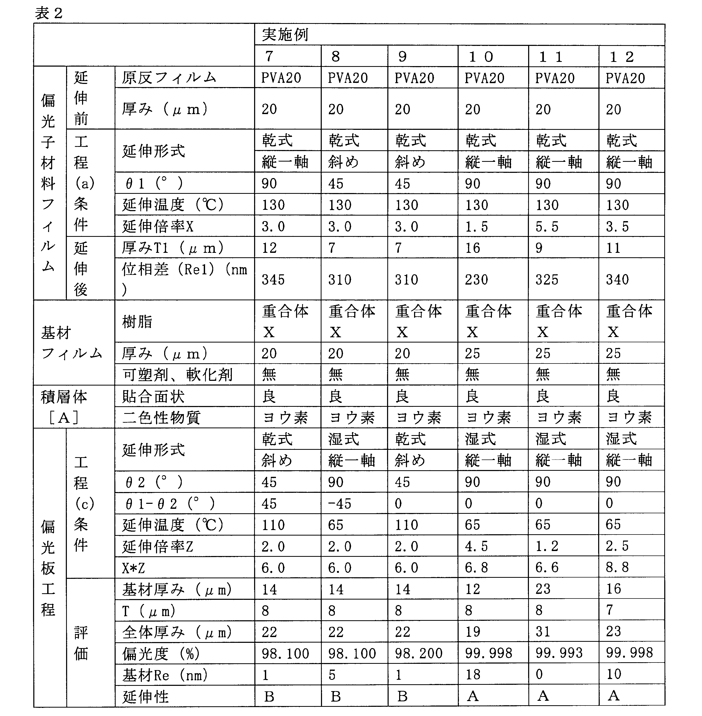
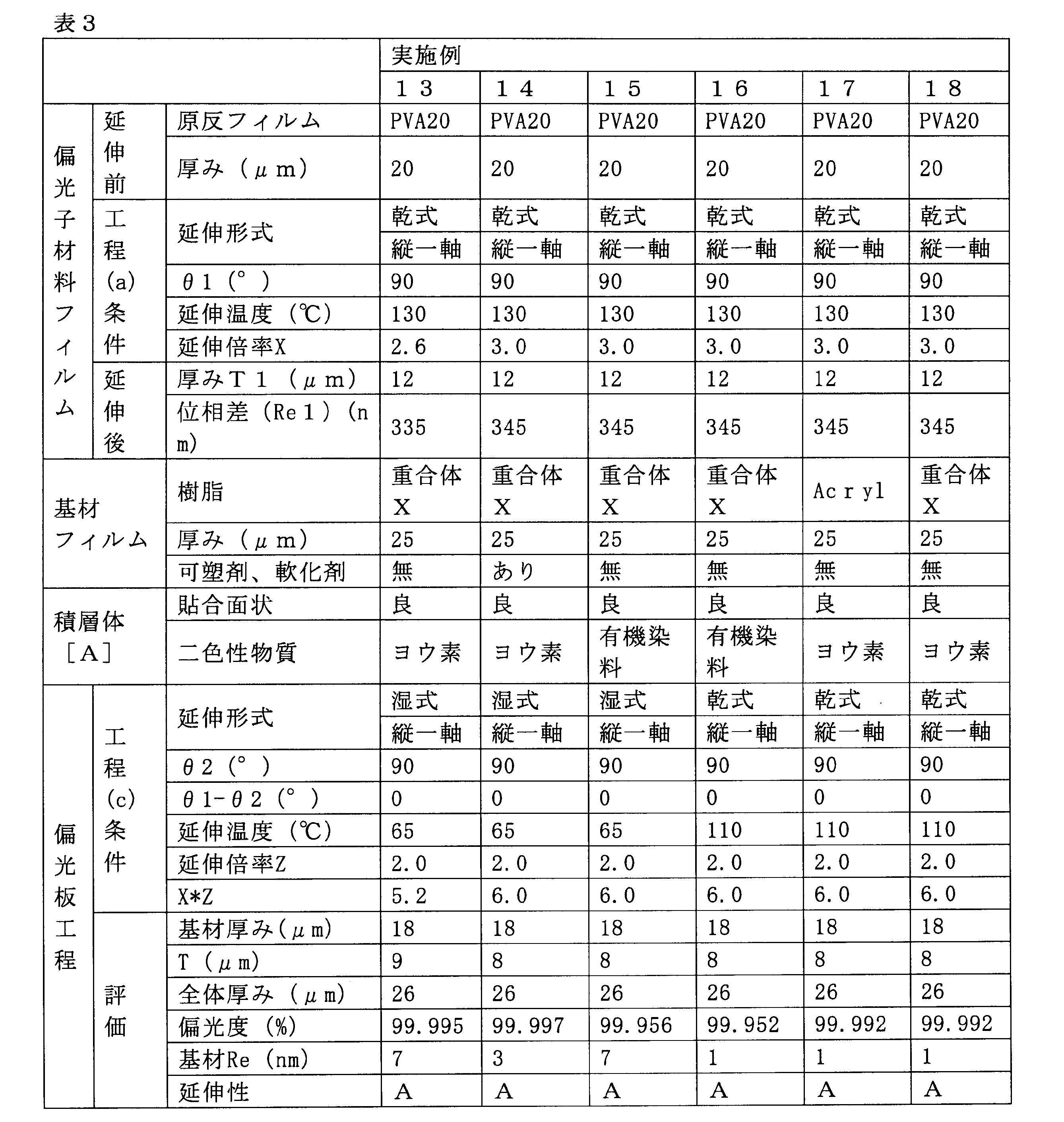

表1~4の結果から、本発明によれば、積層体を延伸する工程を経た後の基材フィルムに発現する位相差を小さくすることができ、これにより基材フィルムを保護フィルムとしても用いることができ、厚みが薄くても効率的に製造することができる偏光板の製造方法を提供しうることが分かる。
1…原反フィルム
10…積層体
11…偏光子材料フィルム
12…基材フィルム
13…接着剤層
100,120,130…偏光板
111…偏光子材料フィルム
112…基材フィルム
113,114…接着剤層
115…保護フィルム
116…粘着剤層
200…製造装置
201,202…繰り出し装置
203…巻き取り装置
204…延伸装置
205…貼り合わせ装置
300…製造装置
301,307…繰り出し装置
302~305…処理装置
306,309…乾燥装置
308…貼り合わせ装置
310…巻き取り装置
400,450…液晶表示装置(表示装置)
410,420…基板
430…液晶層
500,550…有機EL表示装置(表示装置)
510,520…基板
530…発光層
10…積層体
11…偏光子材料フィルム
12…基材フィルム
13…接着剤層
100,120,130…偏光板
111…偏光子材料フィルム
112…基材フィルム
113,114…接着剤層
115…保護フィルム
116…粘着剤層
200…製造装置
201,202…繰り出し装置
203…巻き取り装置
204…延伸装置
205…貼り合わせ装置
300…製造装置
301,307…繰り出し装置
302~305…処理装置
306,309…乾燥装置
308…貼り合わせ装置
310…巻き取り装置
400,450…液晶表示装置(表示装置)
410,420…基板
430…液晶層
500,550…有機EL表示装置(表示装置)
510,520…基板
530…発光層
Claims (22)
- 偏光板の製造方法であって、
偏光子の材料を含む原反フィルムを一以上の方向に延伸倍率Xで延伸して偏光子材料フィルムを得る工程(a)、
前記偏光子材料フィルム上に基材フィルムを設けて積層体[A]を得る工程(b)、
前記積層体[A]を一以上の方向に延伸倍率Zで延伸する工程(c)をこの順で含み、
XおよびZが下記式(1)~(3)の関係を満たし、
工程(c)を経た後の偏光子材料フィルムの厚みTが20μm以下である、偏光板の製造方法。
1.5≦X≦5.5…(1)
1.2≦Z≦5.0…(2)
5.1≦X*Z≦9.0…(3) - 前記工程(b)の後に、前記偏光子材料フィルムを二色性物質で染色する工程(d)を含む、請求項1に記載の偏光板の製造方法。
- 前記工程(c)を、50℃~160℃の温度条件下において行う、請求項1または2に記載の偏光板の製造方法。
- 前記偏光子材料フィルムが、ポリビニルアルコール樹脂からなる、請求項1~3のいずれか1項に記載の偏光板の製造方法。
- 前記工程(c)を経た後の基材フィルムの面内方向の位相差が20nm以下である、請求項1~4のいずれか一項に記載の偏光板の製造方法。
- 前記工程(c)の後に、前記積層体[A]の偏光子材料フィルムに、直接または接着剤を介して保護フィルムを貼合する工程(e1)、または前記偏光子材料フィルムに粘着剤層を設ける工程(e2)を含む、請求項1~5のいずれか一項に記載の偏光板の製造方法。
- 前記基材フィルム層が、シクロオレフィン樹脂、非晶質ポリエステル樹脂、ポリオレフィン樹脂、アクリル樹脂から選ばれる少なくとも1種からなるフィルムである、請求項1~6のいずれか一項に記載の偏光板の製造方法。
- 前記基材フィルムがシクロオレフィン樹脂からなるフィルムであり、
前記シクロオレフィン樹脂が、シクロオレフィン系ポリマーを含み、
前記シクロオレフィン系ポリマーが、ノルボルネン系モノマーの開環重合体の水素化物、ノルボルネン系モノマーとα-オレフィンとの付加共重合体及びその水素化物から選ばれる少なくとも1種からなる、請求項1~7のいずれか一項に記載の偏光板の製造方法。 - 前記基材フィルムがシクロオレフィン樹脂からなるフィルムであり、
前記シクロオレフィン樹脂が、シクロオレフィン系ポリマーを含み、
前記シクロオレフィン系ポリマーが、芳香族ビニル化合物由来の繰り返し単位[I]を主成分とする重合体ブロック[A]と、
芳香族ビニル化合物由来の繰り返し単位[I]及び鎖状共役ジエン化合物由来の繰り返し単位[II]を主成分とする重合体ブロック[B]又は、
鎖状共役ジエン化合物由来の繰り返し単位[II]を主成分とする重合体ブロック[C]と、
からなるブロック共重合体[D]を、
水素化したブロック共重合体水素化物からなる、請求項1~7のいずれか一項に記載の偏光板の製造方法。 - 前記基材フィルム層が、可塑剤及び/又は軟化剤を含有する、請求項1~9のいずれか一項に記載の偏光板の製造方法。
- 前記可塑剤及び/又は軟化剤が、エステル系可塑剤、脂肪族炭化水素ポリマー又はこれらの混合物である、請求項10に記載の偏光板の製造方法。
- 前記工程(a)の延伸方向と偏光子材料フィルムの幅方向とのなす角θ1が90°で、前記工程(c)の延伸方向と積層体[A]の幅方向とのなす角θ2が90°である、請求項1~11のいずれか一項に記載の偏光板の製造方法。
- 前記工程(a)の延伸方向と偏光子材料フィルムの幅方向とのなす角θ1が0°で、前記工程(c)の延伸方向と積層体[A]の幅方向とのなす角θ2が0°である、請求項1~11のいずれか一項に記載の偏光板の製造方法。
- 前記工程(a)の延伸方向と偏光子材料フィルムの幅方向とのなす角θ1、及び、前記工程(c)の延伸方向と積層体[A]の幅方向とのなす角θ2のうち、いずれか一方が90°で、他方が0°である、請求項1~11のいずれか一項に記載の偏光板の製造方法。
- 前記工程(a)の延伸方向と偏光子材料フィルムの幅方向とのなす角θ1が90°で、前記工程(c)の延伸方向と積層体[A]の幅方向とのなす角θ2(°)が下記式(4)を満たす、請求項1~11のいずれか一項に記載の偏光板の製造方法。
θ2≠90…(4) - 前記工程(a)の延伸方向と偏光子材料フィルムの幅方向とのなす角θ1(°)が下記式(5)を満たし、
前記工程(c)の延伸方向と積層体[A]の幅方向とのなす角θ2が90°である、請求項1~11のいずれか一項に記載の偏光板の製造方法。
θ1≠90…(5) - 前記工程(a)の延伸方向と偏光子材料フィルムの幅方向とのなす角θ1(°)、及び前記工程(c)の延伸方向と積層体[A]の幅方向とのなす角θ2(°)が、下記式(6)および下記式(7)を満たす、請求項1~11のいずれか一項に記載の偏光板の製造方法。
θ1≠90…(6)
θ2≠90…(7) - 前記θ1と前記θ2の差の絶対値が50以下である、請求項15~17のいずれか一項に記載の偏光板の製造方法。
- 前記二色性物質が有機染料である、請求項2~18のいずれか一項に記載の偏光板の製造方法。
- 請求項12~14のいずれか一項に記載の製造方法により得られた偏光板を液晶パネルに積層する、表示装置の製造方法。
- 請求項15~17のいずれか一項に記載の製造方法により得られた偏光板を有機ELパネルまたは無機ELパネルに積層する、表示装置の製造方法。
- 請求項19に記載の製造方法により得られた偏光板を車載用表示パネルに積層する、表示装置の製造方法。
Priority Applications (3)
| Application Number | Priority Date | Filing Date | Title |
|---|---|---|---|
| JP2019532607A JP7107316B2 (ja) | 2017-07-25 | 2018-07-23 | 偏光板の製造方法及び表示装置の製造方法 |
| KR1020207001905A KR102530378B1 (ko) | 2017-07-25 | 2018-07-23 | 편광판의 제조 방법 및 표시 장치의 제조 방법 |
| CN201880048316.4A CN110998379B (zh) | 2017-07-25 | 2018-07-23 | 偏振片的制造方法和显示装置的制造方法 |
Applications Claiming Priority (2)
| Application Number | Priority Date | Filing Date | Title |
|---|---|---|---|
| JP2017-143265 | 2017-07-25 | ||
| JP2017143265 | 2017-07-25 |
Publications (1)
| Publication Number | Publication Date |
|---|---|
| WO2019022024A1 true WO2019022024A1 (ja) | 2019-01-31 |
Family
ID=65039722
Family Applications (1)
| Application Number | Title | Priority Date | Filing Date |
|---|---|---|---|
| PCT/JP2018/027549 Ceased WO2019022024A1 (ja) | 2017-07-25 | 2018-07-23 | 偏光板の製造方法及び表示装置の製造方法 |
Country Status (5)
| Country | Link |
|---|---|
| JP (1) | JP7107316B2 (ja) |
| KR (1) | KR102530378B1 (ja) |
| CN (1) | CN110998379B (ja) |
| TW (1) | TWI767034B (ja) |
| WO (1) | WO2019022024A1 (ja) |
Cited By (1)
| Publication number | Priority date | Publication date | Assignee | Title |
|---|---|---|---|---|
| WO2020153233A1 (ja) * | 2019-01-23 | 2020-07-30 | 日本ゼオン株式会社 | 積層体、偏光板、積層体の製造方法、偏光板の製造方法及び表示装置の製造方法 |
Citations (5)
| Publication number | Priority date | Publication date | Assignee | Title |
|---|---|---|---|---|
| JP2015055705A (ja) * | 2013-09-11 | 2015-03-23 | 日東電工株式会社 | 光学フィルム積層体の製造方法 |
| JP2015191224A (ja) * | 2014-03-31 | 2015-11-02 | 日東電工株式会社 | 延伸積層体の製造方法および延伸積層体、ならびに偏光膜の製造方法および偏光膜 |
| JP2015203828A (ja) * | 2014-04-16 | 2015-11-16 | 日東電工株式会社 | 延伸積層体およびその製造方法 |
| JP2017097048A (ja) * | 2015-11-19 | 2017-06-01 | 日本合成化学工業株式会社 | 偏光板用積層体および偏光板 |
| JP2017102439A (ja) * | 2015-11-19 | 2017-06-08 | 日本合成化学工業株式会社 | 偏光膜製造用ポリビニルアルコール系フィルム、およびそれを用いた偏光膜、偏光板、ならびに偏光膜製造用ポリビニルアルコール系フィルムの製造方法 |
Family Cites Families (9)
| Publication number | Priority date | Publication date | Assignee | Title |
|---|---|---|---|---|
| JP4691205B1 (ja) | 2010-09-03 | 2011-06-01 | 日東電工株式会社 | 薄型高機能偏光膜を含む光学フィルム積層体の製造方法 |
| KR101740763B1 (ko) * | 2010-11-10 | 2017-05-26 | 스미또모 가가꾸 가부시키가이샤 | 편광성 적층 필름 및 편광판의 제조 방법 |
| JP5969180B2 (ja) * | 2011-08-02 | 2016-08-17 | 日東電工株式会社 | 処理フィルムの製造方法及びその製造装置 |
| JP5607673B2 (ja) * | 2012-03-09 | 2014-10-15 | 日東電工株式会社 | 光学的表示装置 |
| KR101578610B1 (ko) | 2013-06-18 | 2015-12-17 | 주식회사 엘지화학 | 연신 적층체, 박형 편광자의 제조 방법, 이를 이용하여 제조되는 박형 편광자 및 이를 포함하는 편광판 |
| CN105359011A (zh) * | 2013-07-01 | 2016-02-24 | 日本瑞翁株式会社 | 光学用膜及其制造方法 |
| JP6363344B2 (ja) * | 2014-01-07 | 2018-07-25 | 日東電工株式会社 | 粘着剤層付き片保護偏光フィルムの製造方法 |
| WO2015159679A1 (ja) * | 2014-04-16 | 2015-10-22 | コニカミノルタ株式会社 | 偏光板、偏光板の製造方法、液晶表示装置及び有機エレクトロルミネッセンス表示装置 |
| JP2016200709A (ja) * | 2015-04-10 | 2016-12-01 | コニカミノルタ株式会社 | 偏光板保護フィルム、それが具備された偏光板及び偏光板保護フィルムの製造方法 |
-
2018
- 2018-07-23 WO PCT/JP2018/027549 patent/WO2019022024A1/ja not_active Ceased
- 2018-07-23 JP JP2019532607A patent/JP7107316B2/ja active Active
- 2018-07-23 CN CN201880048316.4A patent/CN110998379B/zh active Active
- 2018-07-23 KR KR1020207001905A patent/KR102530378B1/ko active Active
- 2018-07-24 TW TW107125487A patent/TWI767034B/zh active
Patent Citations (5)
| Publication number | Priority date | Publication date | Assignee | Title |
|---|---|---|---|---|
| JP2015055705A (ja) * | 2013-09-11 | 2015-03-23 | 日東電工株式会社 | 光学フィルム積層体の製造方法 |
| JP2015191224A (ja) * | 2014-03-31 | 2015-11-02 | 日東電工株式会社 | 延伸積層体の製造方法および延伸積層体、ならびに偏光膜の製造方法および偏光膜 |
| JP2015203828A (ja) * | 2014-04-16 | 2015-11-16 | 日東電工株式会社 | 延伸積層体およびその製造方法 |
| JP2017097048A (ja) * | 2015-11-19 | 2017-06-01 | 日本合成化学工業株式会社 | 偏光板用積層体および偏光板 |
| JP2017102439A (ja) * | 2015-11-19 | 2017-06-08 | 日本合成化学工業株式会社 | 偏光膜製造用ポリビニルアルコール系フィルム、およびそれを用いた偏光膜、偏光板、ならびに偏光膜製造用ポリビニルアルコール系フィルムの製造方法 |
Cited By (1)
| Publication number | Priority date | Publication date | Assignee | Title |
|---|---|---|---|---|
| WO2020153233A1 (ja) * | 2019-01-23 | 2020-07-30 | 日本ゼオン株式会社 | 積層体、偏光板、積層体の製造方法、偏光板の製造方法及び表示装置の製造方法 |
Also Published As
| Publication number | Publication date |
|---|---|
| CN110998379A (zh) | 2020-04-10 |
| TW201908785A (zh) | 2019-03-01 |
| KR20200035260A (ko) | 2020-04-02 |
| KR102530378B1 (ko) | 2023-05-09 |
| JPWO2019022024A1 (ja) | 2020-05-28 |
| JP7107316B2 (ja) | 2022-07-27 |
| TWI767034B (zh) | 2022-06-11 |
| CN110998379B (zh) | 2021-12-31 |
Similar Documents
| Publication | Publication Date | Title |
|---|---|---|
| US11573359B2 (en) | Method for producing a polarizing plate | |
| JP7140122B2 (ja) | 積層体及び偏光板の製造方法 | |
| CN111480100B (zh) | 偏振片用层叠体、偏振片、层叠体膜卷、及其制造方法 | |
| JP7140121B2 (ja) | 積層体及び偏光板の製造方法 | |
| JP7107316B2 (ja) | 偏光板の製造方法及び表示装置の製造方法 | |
| JP7124829B2 (ja) | 積層体及び偏光板の製造方法 | |
| JP7294142B2 (ja) | 偏光板用積層体、偏光板、表示装置、及び偏光板の製造方法 | |
| WO2019131666A1 (ja) | 偏光板用積層体、偏光板、偏光板用積層体フィルムロール、偏光板用積層体の製造方法及び偏光板の製造方法 |
Legal Events
| Date | Code | Title | Description |
|---|---|---|---|
| 121 | Ep: the epo has been informed by wipo that ep was designated in this application |
Ref document number: 18838698 Country of ref document: EP Kind code of ref document: A1 |
|
| ENP | Entry into the national phase |
Ref document number: 2019532607 Country of ref document: JP Kind code of ref document: A |
|
| NENP | Non-entry into the national phase |
Ref country code: DE |
|
| 122 | Ep: pct application non-entry in european phase |
Ref document number: 18838698 Country of ref document: EP Kind code of ref document: A1 |