WO2019022084A1 - Système de surveillance d'égout et son procédé de mise en œuvre - Google Patents
Système de surveillance d'égout et son procédé de mise en œuvre Download PDFInfo
- Publication number
- WO2019022084A1 WO2019022084A1 PCT/JP2018/027730 JP2018027730W WO2019022084A1 WO 2019022084 A1 WO2019022084 A1 WO 2019022084A1 JP 2018027730 W JP2018027730 W JP 2018027730W WO 2019022084 A1 WO2019022084 A1 WO 2019022084A1
- Authority
- WO
- WIPO (PCT)
- Prior art keywords
- optical fiber
- sewage
- light
- monitoring system
- sewer
- Prior art date
- Legal status (The legal status is an assumption and is not a legal conclusion. Google has not performed a legal analysis and makes no representation as to the accuracy of the status listed.)
- Ceased
Links
Images





Classifications
-
- G—PHYSICS
- G01—MEASURING; TESTING
- G01D—MEASURING NOT SPECIALLY ADAPTED FOR A SPECIFIC VARIABLE; ARRANGEMENTS FOR MEASURING TWO OR MORE VARIABLES NOT COVERED IN A SINGLE OTHER SUBCLASS; TARIFF METERING APPARATUS; MEASURING OR TESTING NOT OTHERWISE PROVIDED FOR
- G01D5/00—Mechanical means for transferring the output of a sensing member; Means for converting the output of a sensing member to another variable where the form or nature of the sensing member does not constrain the means for converting; Transducers not specially adapted for a specific variable
- G01D5/26—Mechanical means for transferring the output of a sensing member; Means for converting the output of a sensing member to another variable where the form or nature of the sensing member does not constrain the means for converting; Transducers not specially adapted for a specific variable characterised by optical transfer means, i.e. using infrared, visible, or ultraviolet light
- G01D5/32—Mechanical means for transferring the output of a sensing member; Means for converting the output of a sensing member to another variable where the form or nature of the sensing member does not constrain the means for converting; Transducers not specially adapted for a specific variable characterised by optical transfer means, i.e. using infrared, visible, or ultraviolet light with attenuation or whole or partial obturation of beams of light
- G01D5/34—Mechanical means for transferring the output of a sensing member; Means for converting the output of a sensing member to another variable where the form or nature of the sensing member does not constrain the means for converting; Transducers not specially adapted for a specific variable characterised by optical transfer means, i.e. using infrared, visible, or ultraviolet light with attenuation or whole or partial obturation of beams of light the beams of light being detected by photocells
- G01D5/353—Mechanical means for transferring the output of a sensing member; Means for converting the output of a sensing member to another variable where the form or nature of the sensing member does not constrain the means for converting; Transducers not specially adapted for a specific variable characterised by optical transfer means, i.e. using infrared, visible, or ultraviolet light with attenuation or whole or partial obturation of beams of light the beams of light being detected by photocells influencing the transmission properties of an optical fibre
-
- G—PHYSICS
- G01—MEASURING; TESTING
- G01H—MEASUREMENT OF MECHANICAL VIBRATIONS OR ULTRASONIC, SONIC OR INFRASONIC WAVES
- G01H17/00—Measuring mechanical vibrations or ultrasonic, sonic or infrasonic waves, not provided for in the other groups of this subclass
-
- G—PHYSICS
- G01—MEASURING; TESTING
- G01H—MEASUREMENT OF MECHANICAL VIBRATIONS OR ULTRASONIC, SONIC OR INFRASONIC WAVES
- G01H3/00—Measuring characteristics of vibrations by using a detector in a fluid
-
- G—PHYSICS
- G01—MEASURING; TESTING
- G01H—MEASUREMENT OF MECHANICAL VIBRATIONS OR ULTRASONIC, SONIC OR INFRASONIC WAVES
- G01H9/00—Measuring mechanical vibrations or ultrasonic, sonic or infrasonic waves by using radiation-sensitive means, e.g. optical means
-
- G—PHYSICS
- G01—MEASURING; TESTING
- G01B—MEASURING LENGTH, THICKNESS OR SIMILAR LINEAR DIMENSIONS; MEASURING ANGLES; MEASURING AREAS; MEASURING IRREGULARITIES OF SURFACES OR CONTOURS
- G01B11/00—Measuring arrangements characterised by the use of optical techniques
- G01B11/16—Measuring arrangements characterised by the use of optical techniques for measuring the deformation in a solid, e.g. optical strain gauge
Definitions
- the present invention relates to a sewer monitoring system and a method of constructing the same.
- Sewer pipes are buried underground not only in large cities but also in local cities. Sewerage pipes are monitored because they are used for a long time.
- an optical fiber is placed at the bottom of the pipe to check if there is any damage to the sewer due to long-term fatigue, large earthquakes, etc., and an optical fiber acoustic distribution sensor (A system in which a DAS is connected is known (Patent Document 1).
- a first measurement point is installed on the upstream side of a sewer overflow pipe, a second measurement point is installed on the downstream side, and an optical fiber path is directly connected to each of these measurement points.
- a detection device that connects the optical transmission characteristic measurement device to the optical fiber path and obtains the flow velocity or flow rate of sewage from the difference in detection time between the first measurement location and the second measurement location using the optical transmission characteristic measurement device Is known (Patent Document 2).
- Patent Document 3 a remote monitoring system in which a plurality of FBG sensors are provided on an optical fiber and the reflected light from the optical fiber is analyzed by a monitoring device in order to prepare for the overflow of sewage in the sewerage system.
- the conventional example of patent document 2 calculates
- the first measurement point and the second measurement point are probes connected in series to the optical fiber path, respectively, and the probes are installed at preset places. If the dimensions between adjacent probes are long, it is not possible to sufficiently detect the change in the physical quantity of sewage generated at the intermediate position of these probes.
- the conventional example of Patent Document 3 monitors the water level in preparation for the overflow, and does not monitor changes in the sewer pipe itself or the surroundings of the sewer pipe. Moreover, it has a plurality of FBG sensors, and these FBG sensors are provided at preset positions. If the dimensions between adjacent FBG sensors are long, it is not possible to sufficiently detect the change in the physical quantity of sewage generated at the middle position of these probes.
- An object of the present invention is to provide a sewer monitoring system and a construction method thereof, which can perform sewer monitoring accurately and whose optical fiber structure is simple.
- an optical fiber is disposed extending in an axial direction in a portion of a pipe having a sewage flow passage through which sewage flows, which is located above a preset normal water level of the sewage flow passage.
- a light transmitting unit for transmitting pulsed light inside the optical fiber, and a light detecting unit having a light detecting unit for detecting scattered light generated inside the optical fiber due to a change in the environment outside the optical fiber And a detector.
- a sensor is composed of an optical fiber and an optical detector.
- the sewer pipe through which the sewage flows but also the sewage channel that functions as a sewer pipe, the electric cable, the gas pipe, the communication cable, and the water pipe above the sewage channel
- co-grooves in which the stored storage space is arranged in one tube.
- the normal water level is the upper limit position of the sewage that circulates in a normal state, and when the water level rises above this upper limit position, the sewage does not circulate sufficiently, or the sewage flow path itself is damaged. Inconvenient occurs.
- the normal water level is preset.
- the specific position of the optical fiber is not limited as long as it is a portion of the sewage flow path located above the normal water level, and may be the upper portion or the side of the inner circumferential surface of the sewage flow path. It may be a storage space in which an electric cable or the like in the common groove is stored.
- the sensor transmits pulsed light to the optical fiber from the light transmitter of the photodetector. Of the pulsed light sent to the optical fiber, a small amount of light enters the photodetector. In this state, if damage such as a crack occurs in the pipe having the sewage flow passage or the upper part of the pipe is sunk, the environment such as sound, vibration, temperature, strain transmitted to the optical fiber will be changed. Changes in the environment transmitted to the optical fiber result in changes in scattered light. The change in the scattered light is detected by the light detection unit. The light detection unit receives the scattered light signal as a time-series signal. A signal close to the photodetector is received earlier, and a signal farther from the photodetector is received later.
- the reflected light from each position of the optical fiber can be detected.
- monitoring of the tube may be performed using statistical data or AI (Artificial Intelligence) based on data such as sound, vibration, temperature, distortion and the like.
- AI Artificial Intelligence
- the photodetector has a storage unit in which data such as sound is stored in advance as a spectrum pattern, and is created based on the spectrum pattern stored in the storage and data such as sound transmitted from the light detection unit. It is also possible to monitor tube defects, such as damage and depressions, in
- the optical fiber is disposed in a portion of the pipe which is located above the normal water level, sound, vibration, etc. associated with damage or the like caused in the upper part of the sewage flow path or the upper part of the pipe itself. Temperature and the like are transmitted directly to the optical fiber without passing through the sewage. Moreover, in the optical fiber, the place where the change of the scattered light is large is the place closest to the generation source of the environmental change such as sound, vibration, and temperature. Therefore, accurate monitoring can be performed.
- the scattered light detected by the light detector may be at least one of the incident light associated with Rayleigh scattering, the incident light associated with Raman scattering, and the incident light associated with Brillouin scattering.
- Rayleigh scattering occurs due to fluctuations in density in the medium of the optical fiber, and is backscattered light returning at the same frequency as incident light.
- the light intensity of the scattered light changes with the fluctuation of the loss of the optical fiber at the place where the scattered light is generated.
- Raman scattering is generated by the interaction of molecular vibrations in the medium of an optical fiber, and there are both backscattered light and forward scattered light. In Raman scattering, the light intensity of the scattered light changes with the change in temperature of the generated place.
- Brillouin scattering is backscattered light generated by an interaction with a sound wave in the medium of an optical fiber, and its frequency changes with distortion or temperature change in the place where the scattered light is generated.
- the scattered light is one associated with Rayleigh scattering, one associated with Raman scattering, one associated with Brillouin scattering, or a combination thereof.
- the temperature changes before and after the optical fiber is immersed in the sewage the temperature changes before and after the optical fiber is immersed in the sewage.
- the vibration such as sound changes
- the scattered light accompanying the Rayleigh scattering changes
- the temperature changes the scattered light accompanying the Raman scattering changes.
- the temperature changes and the optical fiber is pulled to cause distortion the scattered light associated with Brillouin scattering changes.
- the time domain light detector detects at least one of the scattered light associated with Rayleigh scattering, Raman scattering, and Brillouin scattering, damage to the pipe or damage to the pipe at a specific location in the sewer Detect the inflow of earth and sand, the inundation of the optical fiber with the inflow of earth and sand, the falling off of a part of the optical fiber, the intrusion of human or animal into the inside of the pipe, the collapse or crack of the pipe, the elongation of the pipe, etc. be able to.
- a plurality of vibration sensors are disposed in an axial direction in a portion of the pipe having a sewage flow passage through which the sewage flows and which is located above the preset normal water level of the sewage flow passage.
- the pipe when the pipe having the sewage flow path is damaged such as a crack or the upper part of the pipe is depressed, the pipe vibrates.
- the vibration includes not only sound but also vibration without sound.
- Vibration is detected by a plurality of vibration sensors constituting a vibration sensor array.
- Vibration data is sent from the vibration sensor array to the monitor, and the monitor monitors the pipe using statistical data and AI (Artificial Intelligence) based on the vibration data.
- AI Artificial Intelligence
- the monitor has a storage unit in which data of vibration at normal time is stored in advance as a spectrum pattern, and the monitor is created based on the spectrum pattern stored in this storage unit and the data of vibration sent to the monitor from the vibration sensor array.
- the vibration sensor array detects the vibration generated with damage or depression such as a crack and the like, and the pipe is monitored by the monitor based on the detected vibration.
- the vibration sensor is a microphone
- the vibration sensor array is a microphone array in which a plurality of the microphones are arranged in the lengthwise direction of the sewage flow path.
- a configuration having a sound source floating on the sewage flowing through the sewage flow path is preferable.
- the sound source travels with the flow of sewage in the sewage flow path.
- the vibration sensor array includes an acceleration sensor array that detects vibrations by acceleration.
- the rolling elements it is preferable to have a rolling element that rolls with the sewage flowing through the sewage flow path, and when the rolling element rolls, transmits vibration to a pipe that constitutes the sewage flow path.
- the rolling elements roll with the flow of sewage in the sewage flow path.
- the rolling elements it is possible to measure the flow velocity of the sewage by detecting the vibration transmitted to the pipe constituting the sewage flow path by the light detection unit or the vibration sensor array.
- the pipe having the sewage flow passage through which the sewage flows is axially extended in the portion of the pipe located above the preset normal water level of the sewage flow passage.
- a time domain optical detector is connected which transmits pulsed light inside the optical fiber and detects scattered light generated inside the optical fiber due to a change in the environment outside the optical fiber.
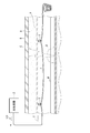
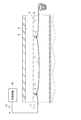
- BRIEF DESCRIPTION OF THE DRAWINGS The schematic block diagram of the sewer monitoring system concerning 1st Embodiment of this invention.
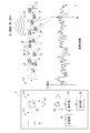
- BRIEF DESCRIPTION OF THE DRAWINGS It is the schematic explaining the basic composition of a sewer monitoring system, Comprising: The schematic structure of a photodetector, and the graph of the relationship of the scattered light which generate
- FIG. 1 The schematic block diagram explaining the condition where a sewer monitoring system is used.
- the Raman scattering LR has a Stokes component RA whose frequency is larger than that of the incident light LO, that is, shifted by several THz than the frequency of the incident light LO, and smaller than that of the incident light LO.
- THz-shifted anti-Stokes component RB There is a THz-shifted anti-Stokes component RB, and the scattered light has extremely smaller light intensity than the scattered light of the Rayleigh scattering LL.
- the light intensity PR of the scattered light accompanying the Raman scattering LR corresponds to the change in temperature of the place where the scattered light is generated. That is, the light intensity of the Stokes component RA increases as the temperature increases, and decreases as the temperature decreases.
- the example of the backscattered light of Raman scattering LR is shown in FIG. 1, there exist forward scattered light other than backscattered light in Raman scattering LR.
- the Brillouin scattering LB has a frequency higher than that of the incident light LO, that is, a Stokes component shifted by several GHz from the frequency of the incident light LO, and a smaller frequency, that is, shifted several GHz than the frequency of the incident light LO There is an anti-Stokes ingredient.
- the light intensity PR of these scattered light is smaller than the light intensity PL of the scattered light accompanying the Rayleigh scattering LL.
- the frequency shift amount TB of the Brillouin scattering LB depends on the distortion and temperature change of the place where the scattered light is generated.
- FIGS. 2 to 4 The schematic structure of the sewer monitoring system of 1st Embodiment is shown by FIG.
- the sewerage monitoring system according to the first embodiment monitors the sewerage pipe P using sound and vibration generated at the upper part of the sewerage pipe P, and the optical fiber 1 and the photodetector 2 are It is an optical fiber acoustic distribution sensor (DAS: Distributed Acoustic Sensing) which it has.
- DAS Distributed Acoustic Sensing
- the optical fiber 1 is disposed at the upper portion of the inner periphery of the sewer pipe P in FIG. 2, but in the first embodiment, a portion positioned above the preset normal water level of the inner periphery of the sewer pipe P If it is, it may be the side part of the inner circumference of sewer pipe P.
- the normal water level is the upper limit position of the sewage that circulates in a normal state, and when the water level rises above this upper limit position, the sewage does not circulate sufficiently, the sewer pipe P itself is damaged, etc. When it happens, it causes inconvenience. The installer of the sewer pipe P previously sets the water level at this normal time.
- the optical fiber 1 is a single mode optical fiber, and the photodetector 2 can detect sound in a frequency band of 0 to 20 kHz with a position resolution of 10 m in a 50 Km section when using a commercially available product.
- the detectable distance is 50 km.
- the sewer pipe P is buried in the underground layer A, and a road B is constructed on the underground layer A.
- a part of the sewer pipe P may not be in the ground, but may be exposed to the ground above the river or the like.
- the inside of the sewer pipe P is open to the atmosphere, and the sewage W discharged from each home, office, etc. is fed through the sewage introduction pipe (not shown).
- the optical fiber 1 is locked at a predetermined position on the upper portion of the inner circumferential surface of the sewer pipe P via the locking member 3.
- the locking member 3 can use a suitable metal fitting, for example, a ring-like metal fitting or a hook-like metal fitting.
- the optical fiber 1 is connected to the light detector 2 at one end side of a line through which light passes.
- a member indicated by reference numeral T is a terminal block.
- FIG. 3 shows a schematic configuration of the light detector 2 and a graph of the relationship between the scattered light generated in the optical fiber 1 and the distance between the optical fiber 1 and the light intensity of the scattered light.
- FIG. 3 shows a schematic configuration of the light detector 2 and a graph of the relationship between the scattered light generated in the optical fiber 1 and the distance between the optical fiber 1 and the light intensity of the scattered light.
- FIG. 3 shows a schematic configuration of the light detector 2 and a graph of the relationship between the scattered light generated in the optical fiber 1 and the distance between the optical fiber 1 and the light intensity of the scattered light.
- the inside of the optical fiber 1 is irradiated with the incident light LO of the laser, it is reflected by a minute structural defect S inside the optical fiber 1 to generate Rayleigh scattering LL. Due to an external factor, the light intensity of the scattered light accompanying the Rayleigh scattering LL changes with the change of the sound and the vibration transmitted to the optical fiber 1.
- the light intensity of the scattered light accompanying the Raman scattering LR changes.
- the light intensity of the scattered light due to the Brillouin scattering LB changes.
- the optical detector 2 transmits the incident light LO to the inside of the optical fiber 1 and the inside of the optical fiber 1 due to the change of the environment outside the optical fiber 1.
- Light detector 22 which detects the scattered light produced
- circulator 23 which sends the pulsed light transmitted by light transmitter 21 to optical fiber 1 and which transmits the scattered light sent from optical fiber 1 to light detector 22, circulator 23 And a light detection unit 22.
- the amplifier 24 amplifies scattered light sent from the circulator 23.
- the storage unit 51 stores an abnormal pattern such as inflow of sediment generated from the sewer or water immersion, and the light detection unit 22.
- the light transmission unit 21 is a light source that emits pulsed light of a predetermined wavelength, or another device.
- the light detection unit 22 receives, as time-series signals, scattered light associated with Rayleigh scattering LL, Raman scattering LR, and Brillouin scattering LB generated inside the optical fiber 1, and has a waveform of the relationship between time and light intensity. Output.
- the light detection unit 22 measures an area of 2 km of the optical fiber 1 in 20 ⁇ s.
- the waveform shown in FIG. 4 is a simplification of the waveform of FIG. 3, and both are substantially the same.
- the scattered light accompanying the Rayleigh scattering LL has a light intensity larger than the scattered light of the Raman scattering LR and the Brillouin scattering LB (see FIG. 1). It can be regarded as only the scattered light accompanying LL. It is to be noted that even if a filter (not shown) for cutting scattered light in a frequency range corresponding to the Raman scattering LR and Brillouin scattering LB and acquiring data of scattered light associated with only Rayleigh scattering LL is used for the light detection unit 22. Good.
- the left and right positions of the waveform are in linear proportion to time.
- lv is the speed of light
- n is the refractive index of the optical fiber 1 and is about 1.41.
- Equation 1 the horizontal axes of the graphs showing the waveforms of FIGS. 3 and 4 are replaced from time to distance. In the graphs of these figures, the distance from the photodetector 2 is long on the right side in the figure, and the distance from the photodetector 2 is short on the left side.
- the position where the scattered light accompanying the Rayleigh scattering LL changes in the optical fiber 1 is the position which is the outside of the optical fiber 1 and closest to the position where the sound and the vibration occur.
- the position at which the scattered light changes with the Raman scattering LR is the position closest to the position outside the optical fiber 1 where the temperature change occurs, and the position at which the scattered light with Brillouin scattering LB changes is This is the position closest to the position where the temperature change and distortion of the optical fiber 1 occur.
- the analysis unit 50 if the statistical data is used and the spectrum pattern of the change NL of the light intensity sent from the amplifier 24 matches the spectrum pattern of the acoustic signal or vibration signal at the abnormal time stored in the storage unit 51, the abnormality is generated. Then, the position of the optical fiber 1 corresponding to the position DL of the spectral pattern determined to be abnormal is determined.
- the agreement is set for each sewer pipe P depending on the size, strength, and other conditions of the sewer pipe P, and is stored in advance in the storage unit 51 or adjusted at the time of setting.
- the result calculated by the analysis unit 50 is displayed on the display unit 25 together with the graph of FIG. 3.
- the map information in which the optical fiber 1 is installed is displayed, and the location where the abnormality of the optical fiber 1 has occurred is displayed on the map information.
- the light detector 2 is connected to one end of the sewer pipe P in which the optical fiber 1 for communication is already installed on the upper part of the inner circumferential surface, and the sewer monitoring system is constructed.
- the sewer pipe P is already buried in the ground.
- the light transmitter 21 of the photodetector 2 is connected to a terminal block T to which one end of the optical fiber 1 already installed in the sewer pipe P is connected.
- the incident light LO is transmitted from the light transmitter 21 of the photodetector 2 to the optical fiber 1.
- the incident light LO sent to the optical fiber 1 a small amount of light is sent to the light detection unit 22 via the circulator 23 and the amplifier 24 as scattered light accompanying Rayleigh scattering LL, Raman scattering LR and Brillouin scattering LB.
- the light detection unit 22 outputs a waveform of the distance and the light intensity, and the waveform is displayed on the display unit 25.
- the analysis unit 50 determines that it is not abnormal in the state where abnormal sound or vibration is not transmitted to the optical fiber 1, and the display unit 25 displays that effect.
- the light detection unit 22 determines that the sewerage is normal, and the display unit 25 does not display a message indicating the abnormality.
- the first embodiment it is possible to detect the noise generated when removing the asphalt of the road B and the vibration of the vehicle passing the road B using an asphalt cutter or a heavy machine, but the magnitudes of these sounds and vibrations Is not displayed as abnormal if it is set below the reference value.
- a portion of the sewer pipe P which is located above the water level in the normal time and extends in the axial direction and the optical fiber 1 is disposed. Therefore, sound, vibration, temperature, etc. accompanying damage etc. generated at the upper part of the pipe itself Since the light is transmitted directly to the optical fiber 1 and detected by the photodetector 2 without passing through the sewage, accurate monitoring can be performed. Moreover, in the optical fiber 1, the place where the change of the scattered light is large is the place closest to the generation source of the environmental change such as the sound, the vibration, the temperature and the like.
- the light detector 2 is detected by the light detection unit 22 that detects scattered light accompanying Rayleigh scattering LL that is generated inside the optical fiber 1 due to changes in sound or vibration outside the optical fiber 1, and the light detection unit 22 Since it has an analysis unit 50 that converts the sound spectrum and vibration spectrum by converting it into sound and vibration based on the results and judges the abnormality of the sewer pipe P, damage to the sewer pipe P at a specific location of the sewer etc. It can be detected.
- the second embodiment is provided with a configuration for detecting scattered light accompanying the Raman scattering LR in order to detect a change in temperature, and the other configurations are the same as the first embodiment.
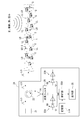
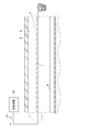
- the whole structure of the sewer monitoring of 2nd Embodiment is shown by FIG.5 and FIG.6. 5 and 6, the sewer monitoring system according to the second embodiment includes the optical fiber 1 installed along the axial direction and the light connected to one end of the optical fiber 1 at the upper portion of the inner circumference of the sewer pipe P. It is an optical fiber temperature distribution sensor (DTS: Distributed Temperature Sensing) having a detector 2A.
- DTS Distributed Temperature Sensing
- the photodetector 2A includes a wavelength filter 26 for passing light of a wavelength (frequency) of a predetermined range among scattered light amplified by the amplifier 24, light detectors 22A and 22B for receiving a signal from the wavelength filter 26, and light An analysis unit 50A that converts data detected by the detection units 22A and 22B into temperature and analyzes whether the temperature is abnormal, a storage unit 51A that stores an abnormal pattern of the temperature generated in the sewer, and a light detection unit 22A, And a display unit 25 for displaying the detection result of 22B.
- the wavelength filter 26 cuts the scattered light in the frequency range corresponding to the Rayleigh scattering LL and the Brillouin scattering LB, and a filter unit for acquiring the scattered light associated with only the Raman scattering LR, and the scattered light associated with the Raman scattered LR as the incident light LO It has a filter section that separates a Stokes component with a higher frequency and an Anti-Stokes component with a lower frequency.
- the light detection units 22A and 22B detect scattered light generated inside the optical fiber 1 due to a change in the environment outside the optical fiber 1.
- the light detection unit 22A receives the Stokes component RA of the scattered light of the Raman scattering LR as a time-series signal, and outputs it as a waveform of the relationship between time and light intensity.
- the light detection unit 22B receives the anti-Stokes component RB of the scattered light of the Raman scattering LR as a time-series signal, and outputs it as a wavelength having a relationship between time and light intensity.
- the analysis unit 50A for the anti-Stokes component RB, from the time-series distribution (see FIG. 6) showing the relationship between the light intensity and the distance (time) between the Stokes component RA and the Anti-Stokes component RB among the scattered light of the Raman scattering LR.
- the ratio of the Stokes component RA is determined.
- the anti-Stokes component RB is higher than the Stokes component RA in the high temperature region DH
- the Stokes component RA is higher than the anti-Stokes component RB in the low temperature region DL. That is, the ratio of the Stokes component RA to the anti-Stokes component RB (RA / RB) is proportional to the temperature.
- the analysis unit 50A determines the ratio (RA / RB) of the Stokes component RA to the anti-Stokes component RB, and this ratio (RA / RB) is the Stokes component to the anti-Stokes component RB at the time of abnormality stored in the storage unit 51A. It is determined whether it is included in the range of the ratio of RA.
- the analysis unit 50A determines the position of the optical fiber 1 when it determines that it is abnormal.
- the result calculated by the analysis unit 50A is displayed on the display unit 25.
- the photodetector 2A is not limited to the above-described configuration, and a known configuration can be employed.
- the incident light LO is periodically transmitted to the optical fiber 1 from the light transmitter 21 of the photodetector 2A.
- the incident light LO sent to the optical fiber 1 a small amount of light is sent to the wavelength filter 26 as scattered light in which the Rayleigh scattering LL, the Raman scattering LR, and the Brillouin scattering LB are mixed.
- the scattered light associated with only the Raman scattering LR among the scattered light is divided into the Stokes component RA and the anti-Stokes component RB, the Stokes component RA is sent to the light detection unit 22A, and the Anti-Stokes component RB is It is sent to the light detection unit 22B.
- the light detection unit 22A detects the Stokes component RA of the scattered light accompanying the Raman scattering LR
- the light detection unit 22B detects the anti-Stokes component RB of the scattered light accompanying the Raman scattering LR.
- the analysis unit 50A the time series distribution showing the relationship between the light intensity and the distance (time) between the Stokes component RA of the scattered light of the Raman scattering LR output from the light detection units 22A and 22B and the anti-Stokes component RB
- the ratio of the Stokes component RA to the Stokes component RB is determined, and it is determined whether this ratio is abnormal.
- the analysis unit 50A determines that it is not abnormal. The result is displayed on the display unit 25.
- the analysis unit 50A obtains the ratio (RA / RB) of the Stokes component RA to the anti-Stokes component RB, and this ratio (RA / RB) is the range of the ratio at the time of abnormality stored in the storage unit 51A. If there is no abnormality associated with the temperature in the sewer pipe P or the optical fiber 1, the analysis unit 50A determines that the abnormality is not present, and this is continuously displayed on the display unit 25. On the other hand, when it is determined that the position is abnormal, the position of the optical fiber 1 is estimated and displayed on the display unit 25 together with the position information.
- the light detection units 22A and 22B detect the scattered light accompanying the Raman scattering LR generated inside the optical fiber 1 due to the temperature change outside the optical fiber 1. The absence of air in the sensor or the dropout of the optical fiber 1 can be detected.
- the sewerage monitoring system according to the third embodiment has a configuration for detecting scattered light accompanying Brillouin scattering LB and Rayleigh scattering LL in order to detect distortion of sewer pipe P and vibrations including temperature and sound.
- the other structure is the same as that of the first embodiment.
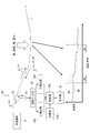
- the sewer monitoring system comprises an optical fiber 1 fixed along the axial direction and an optical detector 2 B connected to one end of the optical fiber 1 at the upper part of the inner circumference of the sewer pipe P; Temperature distribution strain distribution sensor (BOTDR: Brillouin Optical-fiber Time Domain Reflectometer).
- the optical fiber 1 is adhesively fixed along the axial direction at the upper portion of the inner circumferential surface of the sewer pipe P.
- the optical fiber 1 may be locked to the upper part of the inner peripheral surface of the sewer pipe P via the locking member 3 as in the first embodiment, but the inner peripheral surface of the sewer pipe P
- the structure is fixed along the axial direction.
- the photodetector 2B separates the scattered light sent from the circulator 23 into scattered light associated with the Rayleigh scattering LL and scattered light associated with the Brillouin scattering LB, and scattered light associated with the Rayleigh scattering LL separated by the filter 27.
- Scattering signal processing unit 28 processing the signal of Brillouin
- Brillouin scattering signal processing unit 29 processing the scattering light signal accompanying Brillouin scattering LB separated by the filter 27, Rayleigh scattering signal processing unit 28 and Brillouin scattering signal processing
- And an arithmetic unit 30 for calculating distortion by receiving a signal from the unit 29.
- the filter 27 can use a known technique provided with a first Mach-Zehnder interferometer 271 and a second Mach-Zehnder interferometer 272 (author “An Introduction to Distributed Optical Fiber Sensors” author “Arthur H. Hartog "Publisher: see CRC Press, 2017).
- the first Mach-Zehnder interferometer 271 has an optical path difference ⁇ L, and includes a heater 271A that controls the optical path length and an input coupler 271B.
- the second Mach-Zehnder interferometer 272 is provided with an optical isolator 272A and an output coupler 272B that transmit in one direction scattered light associated with Rayleigh scattering LL and scattered light associated with Brillouin scattering LB. In the present embodiment, only one Mach-Zehnder interferometer may be provided.
- the Rayleigh scattering signal processing unit 28 includes a Rayleigh scattering receiving unit 281 that receives the signal output from the output coupler 272B, and a Rayleigh scattering measuring unit 282 that detects Rayleigh scattering based on the signal received by the Rayleigh scattering receiving unit 281.
- the Brillouin scattering signal processing unit 29 includes a Brillouin scattering reception unit 291 received through the input coupler 271B, and a Brillouin scattering measurement unit 292 detecting Brillouin scattering based on a signal received by the Brillouin scattering reception unit 291.
- the computing unit 30 calculates the time (distance) at which the signals greatly change and the time (distance) at that time.
- the ratio of the scattered light of the Rayleigh scattering LL and the Brillouin scattering LB is calculated to determine the distortion of the optical fiber 1, and it is determined whether the distortion is within a prestored tolerance.
- the determination result is displayed on a display unit (not shown) together with the position information. Since the light intensity of the scattered light accompanying the Brillouin scattering LB affects the temperature, a correction means for temperature correction is separately provided.
- a configuration may be employed in which the temperature is detected based on the scattered light accompanying the Raman scattering LR, and the distortion of the optical fiber 1 is corrected based on the detected temperature.
- another distortion detection system for example, the technology described in Japanese Patent No. 6308184 may be used.
- the optical fiber 1 is distorted, and the external sound and vibration change. Then, they propagate inside the optical fiber 1.
- the scattered light accompanying the Rayleigh scattering LL and the Brillouin scattering LB changed inside the optical fiber 1 is sent to the photodetector 2B.
- the filter 27 separates the scattered light associated with the Rayleigh scattering LL and the scattered light associated with the Brillouin scattering LB, and the signal of the scattered light associated with the Rayleigh scattering LL is processed by the Rayleigh scattering signal processing unit 28.
- the signal of the scattered light accompanying the Brillouin scattering LB is processed by the Brillouin scattering signal processing unit 29. Further, the signals from the Rayleigh scattering signal processing unit 28 and the Brillouin scattering signal processing unit 29 are sent to the computing unit 30, and the computing unit 30 obtains distortion of the optical fiber 1, and determines whether this distortion is within an allowable range. Be done. If it is not within the allowable range, a display indicating that it is abnormal is displayed on the display unit together with the position information.
- the photodetector 2B processes the signal of the scattered light accompanying the Rayleigh scattering LL separated by the filter 27 and the filter 27 that separates the scattered light accompanying the Rayleigh scattering LL and the scattered light following the Brillouin scattering LB Signals from the Rayleigh scattering signal processing unit 28, the Brillouin scattering signal processing unit 29, which processes the scattered light signal accompanying the Brillouin scattering LB separated by the filter 27, the Rayleigh scattering signal processing unit 28, and the Brillouin scattering signal processing unit 29 Since the operation unit 30 receives the signal to calculate the distortion, when a tensile force acts on the sewer pipe P due to an earthquake or the like, the abnormality of the sewer pipe P can be determined from the distortion generated in the optical fiber 1.
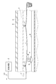
- the fourth embodiment is different from the first embodiment in that the sound source M floating on the sewage W is used to measure the flow velocity of the sewage W, and the other configuration is the first embodiment. It is the same as the form.
- the sound source M floating on the sewage W is installed on the ship Q.
- the sound source M may be a speaker, a bell, a radio, or the like.
- the incident light LO is transmitted from the light transmitter 21 of the photodetector 2 to the optical fiber 1.
- a small amount of light is sent to the light detection unit 22 as scattered light accompanying Rayleigh scattering LL or Raman scattering LR.
- the light detection unit 22 outputs waveforms of distance (time) and light intensity. Due to the sound emitted from the sound source M floating on the sewage W, a portion where the change NL in light intensity is large occurs. Since the sound source M moves with the flow of the sewage W, the portion where the change NL in light intensity is large also moves. Therefore, the flow velocity of the sewage W can be obtained by obtaining the time and distance for the change NL of the light intensity to move in the analysis unit 50. The flow velocity is displayed on the display unit 25.
- the sound source M floats on the sewage flowing through the inside of the sewer pipe P, the sound source M moves along with the flow of the sewage W in the sewer pipe P, and this is detected by the photodetector 2. Flow rate can be measured.
- the rolling element N rolls with the sewage flowing through the sewer pipe P to transmit vibration to the sewer pipe P, and can be, for example, a stone, a block or the like.
- the rolling elements N have a plurality of corner portions on the outer surface and have a weight not to float on the sewage W.
- the flow velocity of the sewage W is determined in the same manner as in the fourth embodiment.
- the incident light LO is transmitted from the light transmitter 21 of the photodetector 2 to the optical fiber 1
- a small amount of the incident light LO is scattered due to the Rayleigh scattering LL or the Raman scattering LR.
- the light is sent to the light detection unit 22 as light.
- the analysis unit 50 obtains the time and distance for the change NL in light intensity to move.
- the flow velocity of W can be determined.
- the flow velocity of the sewage can be measured by detecting the vibration transmitted to the sewer pipe P by the photodetector 2 when the rolling element N rolls with the sewage W.
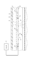
- the sewerage monitoring system includes the vibration sensor array 4 installed along the axial direction and the vibration information detected by the vibration sensor array 4 in the upper part of the inner circumferential surface of the sewer pipe P in a local range. And a monitor 5 for monitoring the sewer pipe P based on The sewerage monitoring system of the sixth embodiment detects sound as vibration generated in the sewer pipe P.
- the vibration sensor 41 is a microphone
- the vibration sensor array 4 is a microphone array in which a plurality of vibration sensors 41 arranged side by side along the axial direction of the sewer pipe P are attached to the sewer pipe P via the support fitting 42 It is.
- the monitor 5 is created based on a storage unit (not shown) in which sound data is stored in advance as a spectrum pattern, the spectrum pattern stored in the storage unit, and data of sound sent from the vibration sensor array 4 to the monitor 5 And a determination unit (not shown) for determining damage, depression, and other inconveniences in the sewer pipe P in comparison with the spectral pattern to be detected.
- monitoring may be performed using AI (Artificial Intelligence).
- the sewer pipe P is installed based on the sound detected by the vibration sensor array 4 installed along the axial direction and having a plurality of vibration sensors 41 and the vibration sensor array 4 Since the monitor 5 to be monitored is provided, the position where the sound is generated can be estimated by contrasting the amount of sound collected by the adjacent vibration sensor 41, and accurate monitoring can be performed visually. it can.
- the vibration sensor 41 is a microphone and the vibration sensor array 4 is a microphone array.
- the vibration sensor 41 is limited to a microphone. Absent.
- a strain gauge type sensor may be used as the vibration sensor 41 in order to detect vibration without sound.
- the vibration sensor array includes an acceleration sensor array having a plurality of acceleration sensors.
- the present invention is not limited to the above-described embodiments, and modifications, improvements, and the like in the range in which the object of the present invention can be achieved are included in the present invention.
- the photodetectors 2, 2A, 2B may have a transmission function of transmitting the results analyzed by the analysis units 50, 50A, 50B to a terminal such as a smartphone.
- the sewer pipe P is already buried in the ground, but in the present invention, if the optical fiber 1 is already installed, the newly manufactured sewer pipe It may be used for P.
- the sewer pipe P of this invention may be arrange
- a sewage channel functioning as a sewer pipe and a storage space in which an electric cable, a gas pipe, a communication cable, and a water pipe above the sewage channel are arranged are disposed in one pipe.
- the optical fiber 1 and the vibration sensor array 4 may be disposed in the storage space above the sewage flow path.
- the abnormality in the sewer pipe P or the like is detected, and the abnormality is displayed on the display unit 25.
- the detection of the abnormality is not displayed on the display unit 25, but the display unit The operator who looks at 25 may judge from the waveform of the distance and the light intensity.
- the analysis units 50, 50A, and 50B use statistical data, but in the present invention, the scattered light output from the optical fiber 1 is used. Based on the signal, the relationship between frequency and time may be displayed as a color map, and the color map may recognize the magnitude of the change in the scattered light based on the color changing with the passage of time.
- the sound source M in the fourth embodiment and the rolling elements N in the fifth embodiment may be moved together with the sewage W inside the sewer pipe P, and the noise and vibration generated at this time may be detected by the vibration sensor array 4 .
- SYMBOLS 1 Optical fiber, 2, 2A, 2B ... Photodetector, 21 ... Light transmission part, 22, 22A, 22B ... Light detection part, 4 ... Vibration sensor array (microphone array), 41 ... Vibration sensor (microphone), 5 ... Monitor, 50, 50A, 50B ... Analysis unit, M ... Sound source, N ... Rolling element
Landscapes
- Physics & Mathematics (AREA)
- General Physics & Mathematics (AREA)
- Measurement Of Mechanical Vibrations Or Ultrasonic Waves (AREA)
- Sewage (AREA)
- Length Measuring Devices Characterised By Use Of Acoustic Means (AREA)
- Testing Or Calibration Of Command Recording Devices (AREA)
- Optical Transform (AREA)
- Measuring Temperature Or Quantity Of Heat (AREA)
Abstract
La présente invention comprend : une fibre optique (1) disposée dans un tuyau (P) comportant un trajet d'écoulement d'eaux usées à travers lequel des eaux usées (W) s'écoulent, la fibre optique (1) étant disposée de façon à s'étendre axialement dans une partie du trajet d'écoulement d'eaux usées positionnée au-dessus d'un niveau d'eau normal prédéfini ; et un photodétecteur (2) qui fonctionne selon un schéma principal temporisé, le photodétecteur (2) comportant un émetteur de lumière (21) qui transmet une lumière pulsée dans la fibre optique (1) et un détecteur de lumière (22) qui détecte la lumière diffusée générée dans la fibre optique (1) en raison d'un changement dans l'environnement à l'extérieur de la fibre optique (1).
Applications Claiming Priority (2)
| Application Number | Priority Date | Filing Date | Title |
|---|---|---|---|
| JP2017-146173 | 2017-07-28 | ||
| JP2017146173A JP2020186911A (ja) | 2017-07-28 | 2017-07-28 | 下水道モニタリングシステム及びその施工方法 |
Publications (1)
| Publication Number | Publication Date |
|---|---|
| WO2019022084A1 true WO2019022084A1 (fr) | 2019-01-31 |
Family
ID=65041438
Family Applications (1)
| Application Number | Title | Priority Date | Filing Date |
|---|---|---|---|
| PCT/JP2018/027730 Ceased WO2019022084A1 (fr) | 2017-07-28 | 2018-07-24 | Système de surveillance d'égout et son procédé de mise en œuvre |
Country Status (2)
| Country | Link |
|---|---|
| JP (1) | JP2020186911A (fr) |
| WO (1) | WO2019022084A1 (fr) |
Cited By (13)
| Publication number | Priority date | Publication date | Assignee | Title |
|---|---|---|---|---|
| JPWO2020213060A1 (fr) * | 2019-04-16 | 2020-10-22 | ||
| WO2021010251A1 (fr) * | 2019-07-17 | 2021-01-21 | 日本電気株式会社 | Système de détection à fibres optiques, équipement de détection à fibres optiques et procédé d'évaluation d'anomalie |
| AU2016303356B2 (en) * | 2015-07-31 | 2021-06-17 | Nuron Limited | Monitoring of fluid flow in an open channel using an optical fibre sensor |
| JPWO2021117749A1 (fr) * | 2019-12-13 | 2021-06-17 | ||
| WO2021256478A1 (fr) * | 2020-06-17 | 2021-12-23 | 日本電気株式会社 | Système de surveillance de protection de câbles d'état de travail, procédé de surveillance de protection de câbles d'état de travail et support de stockage dans lequel est stocké un programme de surveillance de protection de câbles d'état de travail |
| CN114127519A (zh) * | 2019-07-16 | 2022-03-01 | 日本电气株式会社 | 光纤感测系统、光纤感测装置和用于检测管道劣化的方法 |
| CZ309382B6 (cs) * | 2021-07-19 | 2022-10-26 | SATTURN HOLEŠOV spol. s r. o. | Soustava k monitoringu úniku odpadních vod z dvouplášťové kanalizační stoky v reálném čase |
| US20230085614A1 (en) * | 2020-02-13 | 2023-03-16 | Nippon Telegraph And Telephone Corporation | Device and method for detecting inundation of optical fiber |
| US20230088679A1 (en) * | 2020-02-13 | 2023-03-23 | Nippon Telegraph And Telephone Corporation | Device and method for detecting microbend in optical fiber |
| NO20211153A1 (en) * | 2021-09-27 | 2023-03-28 | Leak Detector As | Flexible elongate members in sewage pipelines or channels |
| CN116677944A (zh) * | 2023-05-31 | 2023-09-01 | 才展照明(深圳)有限公司 | 一种雨天具有防护功能的井篦灯及其防护系统 |
| EP4390302A4 (fr) * | 2021-08-16 | 2025-06-25 | Nippon Telegraph And Telephone Corporation | Système de référence d'emplacement d'équipement souterrain de communication optique, procédé de référence d'emplacement d'équipement souterrain de communication optique et dispositif de référence d'emplacement d'équipement souterrain de communication optique |
| CN120313648A (zh) * | 2025-04-07 | 2025-07-15 | 北京联广通网络科技有限公司 | 一种基于多模态散射的融合型光纤扰动检测系统及方法 |
Families Citing this family (1)
| Publication number | Priority date | Publication date | Assignee | Title |
|---|---|---|---|---|
| US11736867B2 (en) * | 2021-01-20 | 2023-08-22 | Nec Corporation | Active microphone for increased DAS acoustic sensing capability |
Citations (9)
| Publication number | Priority date | Publication date | Assignee | Title |
|---|---|---|---|---|
| JP2001084268A (ja) * | 1999-09-16 | 2001-03-30 | Hitachi Ltd | 図面管理装置 |
| JP2002318333A (ja) * | 2001-04-20 | 2002-10-31 | Mole Kogyo:Kk | 下水管内における光ファイバケーブルの敷設方法、及び、光ファイバケーブル保持用鞘管 |
| JP2003304615A (ja) * | 2002-04-10 | 2003-10-24 | Kana Flex Corporation Kk | 通信線用防護管 |
| JP2005346105A (ja) * | 2000-08-07 | 2005-12-15 | Ashimori Ind Co Ltd | 光ファイバーケーブルの敷設方法 |
| JP2005345376A (ja) * | 2004-06-04 | 2005-12-15 | Rikogaku Shinkokai | 変位測定システム及び方法 |
| JP2006183457A (ja) * | 2006-03-02 | 2006-07-13 | Yamaguchi Univ | 下水管損傷予測方法 |
| JP2011128791A (ja) * | 2009-12-16 | 2011-06-30 | Toshiba Corp | 管内計測システムおよび計測装置 |
| US20130021874A1 (en) * | 2008-11-06 | 2013-01-24 | Schlumberger Technology Corporation | Methods for Locating A Cement Sheath in A Cased Wellbore |
| JP2016166839A (ja) * | 2015-03-10 | 2016-09-15 | 日本電気株式会社 | 検出装置及び検出方法 |
-
2017
- 2017-07-28 JP JP2017146173A patent/JP2020186911A/ja active Pending
-
2018
- 2018-07-24 WO PCT/JP2018/027730 patent/WO2019022084A1/fr not_active Ceased
Patent Citations (9)
| Publication number | Priority date | Publication date | Assignee | Title |
|---|---|---|---|---|
| JP2001084268A (ja) * | 1999-09-16 | 2001-03-30 | Hitachi Ltd | 図面管理装置 |
| JP2005346105A (ja) * | 2000-08-07 | 2005-12-15 | Ashimori Ind Co Ltd | 光ファイバーケーブルの敷設方法 |
| JP2002318333A (ja) * | 2001-04-20 | 2002-10-31 | Mole Kogyo:Kk | 下水管内における光ファイバケーブルの敷設方法、及び、光ファイバケーブル保持用鞘管 |
| JP2003304615A (ja) * | 2002-04-10 | 2003-10-24 | Kana Flex Corporation Kk | 通信線用防護管 |
| JP2005345376A (ja) * | 2004-06-04 | 2005-12-15 | Rikogaku Shinkokai | 変位測定システム及び方法 |
| JP2006183457A (ja) * | 2006-03-02 | 2006-07-13 | Yamaguchi Univ | 下水管損傷予測方法 |
| US20130021874A1 (en) * | 2008-11-06 | 2013-01-24 | Schlumberger Technology Corporation | Methods for Locating A Cement Sheath in A Cased Wellbore |
| JP2011128791A (ja) * | 2009-12-16 | 2011-06-30 | Toshiba Corp | 管内計測システムおよび計測装置 |
| JP2016166839A (ja) * | 2015-03-10 | 2016-09-15 | 日本電気株式会社 | 検出装置及び検出方法 |
Cited By (32)
| Publication number | Priority date | Publication date | Assignee | Title |
|---|---|---|---|---|
| AU2016303356B2 (en) * | 2015-07-31 | 2021-06-17 | Nuron Limited | Monitoring of fluid flow in an open channel using an optical fibre sensor |
| US12025477B2 (en) | 2019-04-16 | 2024-07-02 | Nec Corporation | Optical fiber sensor, and monitoring system |
| JPWO2020213060A1 (fr) * | 2019-04-16 | 2020-10-22 | ||
| JP7164027B2 (ja) | 2019-04-16 | 2022-11-01 | 日本電気株式会社 | 光ファイバセンサ、監視システム、センシング位置補正方法、及び、センシング位置補正プログラム |
| CN114127519A (zh) * | 2019-07-16 | 2022-03-01 | 日本电气株式会社 | 光纤感测系统、光纤感测装置和用于检测管道劣化的方法 |
| US12092514B2 (en) | 2019-07-16 | 2024-09-17 | Nec Corporation | Optical fiber sensing system, optical fiber sensing device, and method for detecting pipe deterioration |
| EP4001863A4 (fr) * | 2019-07-16 | 2022-08-17 | NEC Corporation | Système de détection de fibre optique, dispositif de détection de fibre optique et procédé de détection de détérioration de tuyau |
| JP7235115B2 (ja) | 2019-07-17 | 2023-03-08 | 日本電気株式会社 | 光ファイバセンシングシステム、光ファイバセンシング機器、及び異常判断方法 |
| CN114127518A (zh) * | 2019-07-17 | 2022-03-01 | 日本电气株式会社 | 光纤感测系统、光纤感测设备和异常判断方法 |
| US12104947B2 (en) | 2019-07-17 | 2024-10-01 | Nec Corporation | Abnormality assessment device using optical fiber sensing system |
| EP4001862A4 (fr) * | 2019-07-17 | 2022-08-17 | NEC Corporation | Système de détection à fibres optiques, équipement de détection à fibres optiques et procédé d'évaluation d'anomalie |
| WO2021010251A1 (fr) * | 2019-07-17 | 2021-01-21 | 日本電気株式会社 | Système de détection à fibres optiques, équipement de détection à fibres optiques et procédé d'évaluation d'anomalie |
| US20220276089A1 (en) * | 2019-07-17 | 2022-09-01 | Nec Corporation | Optical fiber sensing system, optical fiber sensing equipment, and abnormality assessment method |
| JPWO2021010251A1 (fr) * | 2019-07-17 | 2021-01-21 | ||
| WO2021117749A1 (fr) * | 2019-12-13 | 2021-06-17 | 日本電気株式会社 | Système, dispositif, et procédé de détection |
| JPWO2021117749A1 (fr) * | 2019-12-13 | 2021-06-17 | ||
| US12292325B2 (en) * | 2019-12-13 | 2025-05-06 | Nec Corporation | Detection system, detection device, and detection method |
| JP7315027B2 (ja) | 2019-12-13 | 2023-07-26 | 日本電気株式会社 | 検出システム、検出装置及び検出方法 |
| US20230010341A1 (en) * | 2019-12-13 | 2023-01-12 | Nec Corporation | Detection system, detection device, and detection method |
| US11747294B2 (en) * | 2020-02-13 | 2023-09-05 | Nippon Telegraph And Telephone Corporation | Water immersion detection device and water immersion detection method for detecting inundation of optical fiber |
| US20230085614A1 (en) * | 2020-02-13 | 2023-03-16 | Nippon Telegraph And Telephone Corporation | Device and method for detecting inundation of optical fiber |
| US20230088679A1 (en) * | 2020-02-13 | 2023-03-23 | Nippon Telegraph And Telephone Corporation | Device and method for detecting microbend in optical fiber |
| JPWO2021256478A1 (fr) * | 2020-06-17 | 2021-12-23 | ||
| JP7424487B2 (ja) | 2020-06-17 | 2024-01-30 | 日本電気株式会社 | 作業中ケーブルの保護監視システム、作業中ケーブルの保護監視方法及び作業中ケーブルの保護監視プログラム |
| WO2021256478A1 (fr) * | 2020-06-17 | 2021-12-23 | 日本電気株式会社 | Système de surveillance de protection de câbles d'état de travail, procédé de surveillance de protection de câbles d'état de travail et support de stockage dans lequel est stocké un programme de surveillance de protection de câbles d'état de travail |
| US12455210B2 (en) | 2020-06-17 | 2025-10-28 | Nec Corporation | Working-state cable protection monitoring system, working-state cable protection monitoring method, and storage medium having stored therein working-state cable protection monitoring program |
| CZ309382B6 (cs) * | 2021-07-19 | 2022-10-26 | SATTURN HOLEŠOV spol. s r. o. | Soustava k monitoringu úniku odpadních vod z dvouplášťové kanalizační stoky v reálném čase |
| EP4390302A4 (fr) * | 2021-08-16 | 2025-06-25 | Nippon Telegraph And Telephone Corporation | Système de référence d'emplacement d'équipement souterrain de communication optique, procédé de référence d'emplacement d'équipement souterrain de communication optique et dispositif de référence d'emplacement d'équipement souterrain de communication optique |
| NO347738B1 (en) * | 2021-09-27 | 2024-03-11 | Leak Detector As | Method of obtaining distributed sensor measurement data along a sewage pipeline or channel |
| NO20211153A1 (en) * | 2021-09-27 | 2023-03-28 | Leak Detector As | Flexible elongate members in sewage pipelines or channels |
| CN116677944A (zh) * | 2023-05-31 | 2023-09-01 | 才展照明(深圳)有限公司 | 一种雨天具有防护功能的井篦灯及其防护系统 |
| CN120313648A (zh) * | 2025-04-07 | 2025-07-15 | 北京联广通网络科技有限公司 | 一种基于多模态散射的融合型光纤扰动检测系统及方法 |
Also Published As
| Publication number | Publication date |
|---|---|
| JP2020186911A (ja) | 2020-11-19 |
Similar Documents
| Publication | Publication Date | Title |
|---|---|---|
| WO2019022084A1 (fr) | Système de surveillance d'égout et son procédé de mise en œuvre | |
| Wang et al. | Novel negative pressure wave-based pipeline leak detection system using fiber Bragg grating-based pressure sensors | |
| CN205209700U (zh) | 一种管道全光纤分布式测温监控系统 | |
| KR100803377B1 (ko) | 광섬유 센서를 이용한 분포 개념의 온도 및 변형률 측정을통한 상수도관 누수 및 파손 감시 시스템 | |
| US9594002B2 (en) | Conduit monitoring | |
| CN102197294B (zh) | 管道监控 | |
| US10656041B2 (en) | Detection of leaks from a pipeline using a distributed temperature sensor | |
| CA2567551A1 (fr) | Procede et appareil de detection par fibre optique | |
| CN115371794B (zh) | 基于分布式光纤传感器的地下管廊地表施工事件定位方法 | |
| CN102080954B (zh) | 超远程100km全分布式光纤瑞利与拉曼散射传感器 | |
| KR101956160B1 (ko) | 누수 탐지 장치 | |
| CN113375879B (zh) | 一种多参量多模态高精度管道泄漏监控与定位系统 | |
| CN109210385A (zh) | 一种基于Phase-OTDR的分布式光纤传感系统及方法 | |
| CN107664515B (zh) | 一种光纤周界传感定位系统及入侵扰动点位置的判定方法 | |
| CN115950461A (zh) | 基于光纤传感技术建筑安全监测系统及其监测方法 | |
| CN201935670U (zh) | 一种超远程100km全分布式光纤瑞利与拉曼散射传感器 | |
| CN102997056A (zh) | 一种天然气管道泄漏检测传感器间隔测定方法 | |
| CN101392869A (zh) | 管道安全预警与泄漏报警方法 | |
| KR101607667B1 (ko) | 광섬유를 이용한 지중관로 침하위치 검출시스템 | |
| US20190086243A1 (en) | Fiber optic polarization modulated event monitor | |
| CN204461469U (zh) | 一种光纤温度传感和振动传感共线融合系统 | |
| KR20160005847A (ko) | 변형률과 온도를 동시 측정하기 위한 광섬유 브래그 격자가 통합된 라만 광섬유 시간영역반사계 센서 및 그 센싱 방법 | |
| KR100620868B1 (ko) | 산사태의 발생 위치를 검출하기 위한 otdr 계측 시스템 | |
| CN104236750A (zh) | 油气管道的安全监测系统、方法及分布式远程监控系统 | |
| CN102353339A (zh) | 一种单光纤单端结构的otdr-fbg结构损伤检测系统 |
Legal Events
| Date | Code | Title | Description |
|---|---|---|---|
| 121 | Ep: the epo has been informed by wipo that ep was designated in this application |
Ref document number: 18837524 Country of ref document: EP Kind code of ref document: A1 |
|
| NENP | Non-entry into the national phase |
Ref country code: DE |
|
| 122 | Ep: pct application non-entry in european phase |
Ref document number: 18837524 Country of ref document: EP Kind code of ref document: A1 |
|
| NENP | Non-entry into the national phase |
Ref country code: JP |