WO2019022576A1 - 관 소제 장치 - Google Patents
관 소제 장치 Download PDFInfo
- Publication number
- WO2019022576A1 WO2019022576A1 PCT/KR2018/008576 KR2018008576W WO2019022576A1 WO 2019022576 A1 WO2019022576 A1 WO 2019022576A1 KR 2018008576 W KR2018008576 W KR 2018008576W WO 2019022576 A1 WO2019022576 A1 WO 2019022576A1
- Authority
- WO
- WIPO (PCT)
- Prior art keywords
- tube
- spacer ring
- cleaning
- scavenging
- ring
- Prior art date
- Legal status (The legal status is an assumption and is not a legal conclusion. Google has not performed a legal analysis and makes no representation as to the accuracy of the status listed.)
- Ceased
Links
Images


Classifications
-
- B—PERFORMING OPERATIONS; TRANSPORTING
- B08—CLEANING
- B08B—CLEANING IN GENERAL; PREVENTION OF FOULING IN GENERAL
- B08B9/00—Cleaning hollow articles by methods or apparatus specially adapted thereto
- B08B9/02—Cleaning pipes or tubes or systems of pipes or tubes
- B08B9/027—Cleaning the internal surfaces; Removal of blockages
- B08B9/04—Cleaning the internal surfaces; Removal of blockages using cleaning devices introduced into and moved along the pipes
- B08B9/043—Cleaning the internal surfaces; Removal of blockages using cleaning devices introduced into and moved along the pipes moved by externally powered mechanical linkage, e.g. pushed or drawn through the pipes
- B08B9/0436—Cleaning the internal surfaces; Removal of blockages using cleaning devices introduced into and moved along the pipes moved by externally powered mechanical linkage, e.g. pushed or drawn through the pipes provided with mechanical cleaning tools, e.g. scrapers, with or without additional fluid jets
-
- B—PERFORMING OPERATIONS; TRANSPORTING
- B05—SPRAYING OR ATOMISING IN GENERAL; APPLYING FLUENT MATERIALS TO SURFACES, IN GENERAL
- B05B—SPRAYING APPARATUS; ATOMISING APPARATUS; NOZZLES
- B05B13/00—Machines or plants for applying liquids or other fluent materials to surfaces of objects or other work by spraying, not covered by groups B05B1/00 - B05B11/00
- B05B13/02—Means for supporting work; Arrangement or mounting of spray heads; Adaptation or arrangement of means for feeding work
- B05B13/0278—Arrangement or mounting of spray heads
-
- B—PERFORMING OPERATIONS; TRANSPORTING
- B05—SPRAYING OR ATOMISING IN GENERAL; APPLYING FLUENT MATERIALS TO SURFACES, IN GENERAL
- B05B—SPRAYING APPARATUS; ATOMISING APPARATUS; NOZZLES
- B05B13/00—Machines or plants for applying liquids or other fluent materials to surfaces of objects or other work by spraying, not covered by groups B05B1/00 - B05B11/00
- B05B13/06—Machines or plants for applying liquids or other fluent materials to surfaces of objects or other work by spraying, not covered by groups B05B1/00 - B05B11/00 specially designed for treating the inside of hollow bodies
- B05B13/0627—Arrangements of nozzles or spray heads specially adapted for treating the inside of hollow bodies
-
- B—PERFORMING OPERATIONS; TRANSPORTING
- B08—CLEANING
- B08B—CLEANING IN GENERAL; PREVENTION OF FOULING IN GENERAL
- B08B3/00—Cleaning by methods involving the use or presence of liquid or steam
- B08B3/04—Cleaning involving contact with liquid
- B08B3/08—Cleaning involving contact with liquid the liquid having chemical or dissolving effect
-
- B—PERFORMING OPERATIONS; TRANSPORTING
- B08—CLEANING
- B08B—CLEANING IN GENERAL; PREVENTION OF FOULING IN GENERAL
- B08B9/00—Cleaning hollow articles by methods or apparatus specially adapted thereto
- B08B9/02—Cleaning pipes or tubes or systems of pipes or tubes
- B08B9/027—Cleaning the internal surfaces; Removal of blockages
- B08B9/032—Cleaning the internal surfaces; Removal of blockages by the mechanical action of a moving fluid, e.g. by flushing
- B08B9/035—Cleaning the internal surfaces; Removal of blockages by the mechanical action of a moving fluid, e.g. by flushing by suction
-
- B—PERFORMING OPERATIONS; TRANSPORTING
- B08—CLEANING
- B08B—CLEANING IN GENERAL; PREVENTION OF FOULING IN GENERAL
- B08B9/00—Cleaning hollow articles by methods or apparatus specially adapted thereto
- B08B9/02—Cleaning pipes or tubes or systems of pipes or tubes
- B08B9/027—Cleaning the internal surfaces; Removal of blockages
- B08B9/04—Cleaning the internal surfaces; Removal of blockages using cleaning devices introduced into and moved along the pipes
- B08B9/043—Cleaning the internal surfaces; Removal of blockages using cleaning devices introduced into and moved along the pipes moved by externally powered mechanical linkage, e.g. pushed or drawn through the pipes
-
- F—MECHANICAL ENGINEERING; LIGHTING; HEATING; WEAPONS; BLASTING
- F28—HEAT EXCHANGE IN GENERAL
- F28G—CLEANING OF INTERNAL OR EXTERNAL SURFACES OF HEAT-EXCHANGE OR HEAT-TRANSFER CONDUITS, e.g. WATER TUBES OR BOILERS
- F28G1/00—Non-rotary, e.g. reciprocated, appliances
- F28G1/16—Non-rotary, e.g. reciprocated, appliances using jets of fluid for removing debris
- F28G1/163—Non-rotary, e.g. reciprocated, appliances using jets of fluid for removing debris from internal surfaces of heat exchange conduits
-
- F—MECHANICAL ENGINEERING; LIGHTING; HEATING; WEAPONS; BLASTING
- F28—HEAT EXCHANGE IN GENERAL
- F28G—CLEANING OF INTERNAL OR EXTERNAL SURFACES OF HEAT-EXCHANGE OR HEAT-TRANSFER CONDUITS, e.g. WATER TUBES OR BOILERS
- F28G15/00—Details
-
- F—MECHANICAL ENGINEERING; LIGHTING; HEATING; WEAPONS; BLASTING
- F28—HEAT EXCHANGE IN GENERAL
- F28G—CLEANING OF INTERNAL OR EXTERNAL SURFACES OF HEAT-EXCHANGE OR HEAT-TRANSFER CONDUITS, e.g. WATER TUBES OR BOILERS
- F28G15/00—Details
- F28G15/003—Control arrangements
-
- F—MECHANICAL ENGINEERING; LIGHTING; HEATING; WEAPONS; BLASTING
- F28—HEAT EXCHANGE IN GENERAL
- F28G—CLEANING OF INTERNAL OR EXTERNAL SURFACES OF HEAT-EXCHANGE OR HEAT-TRANSFER CONDUITS, e.g. WATER TUBES OR BOILERS
- F28G15/00—Details
- F28G15/04—Feeding and driving arrangements, e.g. power operation
-
- H—ELECTRICITY
- H02—GENERATION; CONVERSION OR DISTRIBUTION OF ELECTRIC POWER
- H02K—DYNAMO-ELECTRIC MACHINES
- H02K11/00—Structural association of dynamo-electric machines with electric components or with devices for shielding, monitoring or protection
- H02K11/20—Structural association of dynamo-electric machines with electric components or with devices for shielding, monitoring or protection for measuring, monitoring, testing, protecting or switching
Definitions
- the present invention relates to a pipe cleaning apparatus, and more particularly, to a pipe cleaning apparatus capable of easily removing foreign matters in a pipe.
- Pipes are used in a variety of industries.
- the pipe is disposed inside the ondol.
- the hot water flows along the pipe, and the heat is transferred from the hot water to the ondol.
- the tube can be used in a heat exchanger installed in an automobile, an air conditioner, an electric battery or the like.
- the tube used for the heat exchanger (hereinafter referred to as "tube for heat exchanger") has a very long length.
- such a tube can be folded several times due to space problems and heat exchange efficiency problems. That is, the tube for a heat exchanger has a very complicated shape extending while bending several times.
- the tube for a heat exchanger may be manufactured by combining a plurality of straight tubes and a plurality of bent tubes or the like. Further, the tube for the heat exchanger can be integrally manufactured through die casting.
- the tube for the heat exchanger may contain foreign matter therein. Therefore, after manufacturing the tube for the heat exchanger, foreign substances inside the tube must be removed.
- the heat exchanger tube has a very long length and a complicated shape. Therefore, it is important to be able to easily remove foreign substances inside the tube having a very long length and a complicated shape.
- An embodiment of the present invention can provide a pipe cleaning apparatus capable of cleaning the inside of a pipe having a complicated shape.
- the pipe cleaning apparatus includes a flexible cleaning tube 100 having an internal flow path 110; And a spacer ring (200) disposed on an outer circumferential surface of the scavenging tube (100), the spacer ring (200) comprising: a first spacer ring (210) disposed at an end of the scavenging tube (100); And at least one second spacer ring (230) spaced apart from the first spacer ring (210).
- the scavenging tube 100 comprises a polytetrafluoroethylene (PTFE) tube.
- PTFE polytetrafluoroethylene
- the scavenging tube 100 includes at least one first tube protrusion 131 protruding radially from the outer circumferential surface of the scavenging tube 100.
- the first tube protrusions 131 are spaced along the longitudinal direction of the scavenging tube 100.
- the spacer ring 200 has a first receiving groove 200a into which the first tube projection 131 is inserted.
- the spacer ring 200 includes at least one ring protrusion 250 that protrudes radially from the outer circumferential surface of the spacer ring 200.
- the ring protrusions 250 are circumferentially spaced.
- the ring protrusion 250 has a hemispherical shape that is convex in the radial direction.
- the scavenging tube 100 further includes a circular second tube protrusion 133 protruding from the end of the scavenging tube 100 in the longitudinal direction of the scavenging tube 100.
- the first spacer ring 210 has a second receiving groove 211 into which the second tube projection 133 is inserted and a convex curved surface 142 protruding in the projecting direction of the second tube projection 133.
- a circular spacer end 213 having a first end 212a and a second end 213b.
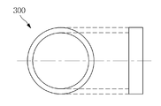
- it further includes an auxiliary ring 300 disposed between the spacer rings 300.
- a small-bodied fluid supply pipe 400 disposed inside the scavenging tube 100 for supplying bodily fluid; And a small bore liquid suction pipe 500 disposed inside the cleaning tube 100 and spaced apart from the baffle liquid supply pipe 400.
- the cleaning solution supply unit 600 supplies the cleaning solution to the cleaning tube 100 or the cleaning solution supply pipe 400.
- the decant solution supply unit 600 includes a hoisting drum 610 on which the cleaning tube 100 is wound; A driving motor 630 connected to the hoisting drum 610; A torque sensor (650) connected to the hoisting drum; And a controller 670 for controlling the operation of the driving motor 630.
- the controller 670 controls the operation of the drive motor 630 in accordance with a signal from the torque sensor 650.
- a tube 700 into which the scavenging tube 100 is inserted into which the scavenging tube 100 is inserted; And a guiding part 800 disposed between the hoisting drum 610 and the pipe 700 to guide the cleaning tube 100.
- the apparatus further includes a blocking member 900 that shields one end of the tube 700, and the guide unit 800 at least partially shields the other end of the tube 700.
- One embodiment of the present invention comprises a flexible cleansing tube inserted into a tube having a complicated shape and at least one spacer ring disposed on an outer circumferential surface of the cleansing tube.
- the scavenging tube can easily bend depending on the shape of the tube inside the tube. Further, the spacer ring maintains a gap between the cleaning tube and the inner circumferential surface of the tube. Bleed solution discharged from the end of the cleaning tube may be discharged from the tube through the tube between the cleaning tube and the tube.
- an embodiment of the present invention may further include an auxiliary ring.
- the auxiliary ring is disposed between the spacer rings.
- the auxiliary ring may be at least partially in contact with the spacer ring disposed in front of and behind the auxiliary ring. At this time, the auxiliary ring presses the spacer ring. Thereby, the scavenging tube can be easily advanced inside the tube.
- FIG. 1 is a view schematically showing a pipe cleaning apparatus according to an embodiment of the present invention.
- FIG. 2 is a perspective view showing the scouring tube shown in FIG. 1.
- FIG. 2 is a perspective view showing the scouring tube shown in FIG. 1.
- FIG. 3 is a cross-sectional view of the scouring tube shown in Fig.
- FIG. 4 is a cross-sectional view taken along line I-I 'of FIG. 2;
- FIGS. 5-7 illustrate various embodiments of the cleaning tube shown in FIG.
- FIG. 8 is a view showing one embodiment of the first spacer ring shown in FIG. 1; FIG.
- FIG. 9 is a cross-sectional view of the first spacer ring shown in Fig.
- FIG. 10 is a view showing an embodiment of the second spacer ring shown in Fig.
- FIG. 11 is a cross-sectional view of the second spacer ring shown in Fig.
- Fig. 12 is a view showing another embodiment of the piping system shown in Fig. 1. Fig.
- FIG. 13 is a view showing an embodiment of the auxiliary ring shown in Fig.
- FIG. 14 is a view showing another embodiment of the pipe cleaning apparatus shown in Fig.
- 15 and 16 are perspective views illustrating a tube according to an embodiment of the present invention.
- 17 is a view showing an embodiment of a decant solution supply unit according to the present invention.
- FIG. 18 and 19 are views for explaining the operation of the pipe cleaning apparatus shown in Fig.
- FIG. 20 is a view for explaining the operation of the pipe cleaning apparatus shown in Fig.
- first, second, third, etc. in this specification may be used to describe various components, but such components are not limited by these terms. The terms are used for the purpose of distinguishing one element from another.
- first component may be referred to as a second or third component, and similarly, the second or third component may be alternately named.
- FIG. 2 is a perspective view showing the cleaning tube 100 shown in FIG. 1
- FIG. 3 is a cross-sectional view taken along the line II-II of FIG. Sectional view of the cleaning tube 100 shown.
- a tubing device 10 may include a scavenging tube 100 and a spacer ring 200.
- the cleaning tube 100 has a very long length. Further, the cleaning tube 100 has an internal flow path 110.
- the cleaning tube 100 may be inserted into a tube to be described later to remove foreign matter inside the tube.
- the scavenging tube 100 may comprise a polytetrafluoroethylene (PTFE) tube.
- PTFE tubes are very stable due to strong chemical bonding of fluorine and carbon.
- the PTFE tube is chemically inert.
- the PTFE tube has properties such as heat resistance, non-stickiness, excellent insulation stability, and low coefficient of friction.
- the PTFE tube has flexibility. That is, the PTFE tube has a good bending property.
- the scavenging tube 100 has a cylindrical shape. That is, the cleaning tube 100 has the internal flow path 110. So that a blanket solution for removing foreign matter in the tube can flow through the inner flow path 110. Meanwhile, the cleaning tube 100 may include the tube protrusion 130.
- FIG. 4 is a cross-sectional view taken along line I-I 'of FIG. 2
- FIGS. 5 to 7 are views showing various embodiments of the scavenging tube 100 shown in FIG.
- the tube protrusion 130 may include a first tube protrusion 131 and a second tube protrusion 133.
- the first tube projection 131 protrudes in the radial direction from the outer peripheral surface of the cleaning tube 100.
- the first tube protrusion 131 may extend in the circumferential direction along the outer circumferential surface of the scavenging tube 100.
- the first tube projection part 131 can be inserted into a spacer ring 200 to be described later.
- the first tube projection 131 may have a constant width.
- the cleaning tube 100 may include a plurality of first tube protrusions 131 disposed on the same circumference.
- the plurality of first tube projection parts 131 are disposed apart from each other on the same circumference.
- the cleaning tube 100 may include two first tube projection parts 131 disposed on the same circumference.
- the two first tube protrusions 131 may be disposed to face each other on the outer circumferential surface of the scavenging tube 100.
- the cleaning tube 100 may include four first tube protrusions 131 disposed on the same circumference.
- the four first tube projection parts 131 may be disposed at an angle of 90 degrees with respect to each other on the outer peripheral surface of the cleaning agent tube 100.
- the first tube protrusion 131 may have a curved surface that is convex in the radial direction. Particularly, at least a part of the first tube projection 131 may have a hemispherical shape which is convex in the radial direction. Meanwhile, the cleaning tube 100 may have eight first tube projection parts 131 arranged on the same circumference. The eight first tube projection parts 131 may be disposed at an angle of 45 degrees with respect to each other on the outer peripheral surface of the cleaning agent tube 100.
- the second tube projection 133 is disposed at the end of the cleaning tube 100.
- the second tube protrusion 133 may protrude in the longitudinal direction of the scavenging tube 100. That is, the second tube protrusion 133 can protrude from the end of the scavenging tube 100 in a circular shape.
- the spacer ring 200 may be disposed on the outer circumferential surface of the scavenging tube 100.
- the plurality of spacer rings 200 are spaced apart from each other along the longitudinal direction of the scavenging tube 100.
- the spacer ring 200 may have a first receiving groove 200a into which the first tube projection 131 is inserted.
- the spacer ring 200 is not moved along the longitudinal direction of the scavenging tube 100 by the first tube projection part 131.
- the spacer ring 200 may include a first spacer ring 210 and a second spacer ring 230.
- the spacer ring 200 can maintain a gap between the tube 700 to be described later and the cleaning tube 100 inserted in the tube 700.
- the spacer ring 200 can facilitate the movement of the cleaning tube 100 inserted into the tube 700.
- the spacer ring 200 can be rotatably disposed in the scavenging tube 100.
- FIG. 8 is a view showing one embodiment of the first spacer ring 210 shown in FIG. 1
- FIG. 9 is a sectional view of the first spacer ring 210 shown in FIG.
- the end of the scavenging tube 100 may be inserted into the first spacer ring 210.
- the first spacer ring 210 may have a first receiving groove 200a.
- the first tube protrusion 131 can be inserted into the first receiving groove 200a.
- the first spacer ring 210 may include a circular spacer end 213.
- the circular spacer end 213 may have a second receiving groove 211.
- the second tube projection 133 can be inserted into the second receiving groove 211.
- the circular spacer end 213 protrudes from the end of the scavenging tube 100 in the longitudinal direction of the scavenging tube 100.
- the circular spacer end 213 protrudes in a circular shape.
- the circular spacer end portion 213 has a convex curved surface in the protruding direction of the second tube projection portion 133.
- the first spacer ring 210 may have a first inner diameter d1 corresponding to the inner diameter of the scavenging tube 100.
- the first spacer ring 210 may include at least one ring protrusion 250.
- the ring protrusions 250 are spaced apart from each other along the outer peripheral surface of the first spacer ring 210.
- the ring protrusion 250 may protrude radially from the outer circumferential surface of the first spacer ring 210.
- the ring protrusion 250 may have a curved surface that is convex in the radial direction.
- at least a part of the ring protrusion 250 may have a hemispherical shape that is convex in the radial direction.
- the first spacer ring 210 may have eight ring protrusions 250.
- the eight ring protrusions 250 may be disposed at an angle of 45 degrees on the outer circumferential surface of the first spacer ring 210.
- FIG. 10 shows one embodiment of the second spacer ring 230 shown in FIG. 1
- FIG. 11 is a cross-sectional view of the second spacer ring 230 shown in FIG.
- the second spacer rings 230 may be disposed in plural along the longitudinal direction of the scavenging tube 100.
- the second spacer ring 230 may have a first receiving groove 200a.
- the first tube protrusion 131 may be inserted into the first receiving groove 200a.
- the second spacer ring 230 may have a second inner diameter d2 corresponding to the outer diameter of the scavenging tube 100.
- the second spacer ring 230 may include at least one ring protrusion 250.
- the ring protrusions 250 are spaced apart from each other in the circumferential direction along the outer circumferential surface of the second spacer ring 230.
- the ring protrusion 250 may project radially from the outer peripheral surface of the second spacer ring 230.
- the ring protrusion 250 may have a curved surface that is convex in the radial direction.
- at least a part of the ring protrusion 250 may have a hemispherical shape that is convex in the radial direction.
- the second spacer ring 230 may have eight ring protrusions 250.
- the eight ring protrusions 250 may be disposed at an angle of 45 degrees on the outer circumferential surface of the second spacer ring 230.
- Fig. 12 is a view showing another embodiment of the piping apparatus 10 shown in Fig. 1
- Fig. 13 is a view showing an embodiment of the auxiliary ring 300 shown in Fig.
- the pipe cleaning apparatus 10 may further include an auxiliary ring 300.
- the auxiliary ring 300 may be disposed on the outer circumferential surface of the scavenging tube 100.
- the auxiliary ring 300 may be disposed between the spacer rings 200.
- the auxiliary ring 300 may have a ring shape.
- the cleaning tube 100 may be inserted into the auxiliary ring 300.
- the auxiliary ring 300 can be rotated on the scavenging tube 100 or moved along the longitudinal direction of the scavenging tube 100.
- the movement of the auxiliary ring 300 can be limited by the spacer ring 200 arranged before and after the auxiliary ring 300.
- the auxiliary ring 300 can press the spacer ring 200 in the advancing direction of the cleaning tube 100 while the cleaning tube 100 passes through the inside of the bent tube. As a result, the cleaning tube 100 can easily pass through the inside of the bent tube.
- Fig. 14 is a view showing another embodiment of the piping system 10 shown in Fig.
- the pipe cleaning apparatus 10 may further include a baffle solution supply pipe 400 and a baffle solution suction pipe 500.
- the submerged solution supply pipe 400 and the submerged solution suction pipe 500 may be disposed inside the scavenging tube 100. Therefore, the bodily fluid supply tube 400 and the bodily fluid suction tube 500 may have an outer diameter smaller than the inner diameter of the scavenging tube 100.
- the submerged solution supply pipe 400 and the submerged solution suction pipe 500 may include the same material as the scavenging tube 100.
- the blanket solution supply pipe 400 may be connected to a blanket solution supply unit 600, which will be described later.
- the bovine fluid suction tube 500 may be connected to the bovine fluid suction unit 510.
- the blanket liquid supply unit 600 may supply the blanket liquid to the blanket liquid supply pipe 400.
- the blanket liquid supply unit 600 can supply the blanket liquid directly to the cleaning tube 100. A detailed description thereof will be described later.
- the small fluid suction portion 510 may include a vacuum pump (not shown).
- the submerged liquid suction pipe (500) connected to the vacuum pump can suck the submerged liquid discharged from the submerged liquid supply pipe (400).
- 15 and 16 are perspective views illustrating a tube 700 according to an embodiment of the present invention.
- the pipe cleaning apparatus 10 may further include a pipe 700.
- the tube 700 may include foreign substances in the manufacturing process.
- the tube 700 may have a very long length.
- the tube 700 may have multiple bends. Because of spatial constraints, the tube 700 can have a very long length with multiple bends. That is, the tube 700 can have a very complicated shape. Therefore, it may be difficult to remove the foreign matter in the tube 700 having a complicated shape.
- a pipe cleaning apparatus 10 according to an embodiment of the present invention is required.
- 17 is a view showing an embodiment of the decant solution supply unit 600 according to the present invention.
- the pipe cleaning apparatus 10 may further include a blanket liquid supply unit 600.
- the submerged solution supply unit 600 may include a hoisting drum 610, a driving motor 630 for driving the hoisting drum 610, a torque sensor 650 connected to the hoisting drum 610, and a control unit 670.
- the scavenging tube 100 may be wound at least partially on the hoisting drum 610.
- the hoisting drum 610 may be connected to the drive motor 630.
- the torque sensor 650 may be connected to the hoisting drum 610. In one embodiment, the torque sensor 650 may be coupled to the shaft of the hoisting drum 610.
- the driving motor 630 and the torque sensor 650 may be connected to the controller 670.
- the control unit 670 can control the operation of the driving motor 630 according to the signal from the torque sensor 650.
- the cleaning tube 100 may be connected to the high-pressure pump 690.
- the high-pressure pump 690 compresses the decant fluid supplied from the decant fluid reservoir (not shown) to a high pressure.
- the blanket liquid supply unit 600 may further include a blanket liquid heating unit (not shown).
- the blanket solution heating section can be disposed before and after the high-pressure pump 690 to heat the blanket solution to a high temperature.
- the tube cleaning apparatus 10 includes a shielding member 900 shielding one end of the tube 700 and a guide unit 800 shielding at least a portion of the other end of the tube 700 .
- the guide unit 800 may be disposed between the hoisting drum 610 and the pipe 700.
- the guide portion 800 may have a tubular shape.
- the guide portion 800 may have a plurality of rod shapes.
- the plurality of rods may be disposed apart from each other.
- the cleaning tube 100 may be inserted into the guide portion 800. Accordingly, the guide part 800 can guide the movement of the cleaning agent tube 100 inserted into the tube 700.
- the blocking member 900 may be disposed at one end of the tube 700.
- the guide part 800 may be disposed at the other end of the pipe 700.
- the blocking member 900 may shield one end of the tube 700.
- the guide portion 800 can shield at least a part of the other end of the tube 700.
- the blocking member 900 and the guide portion 800 may be at least partially inserted into the tube 700.
- one end of the tube 700 may be inserted into the blocking member 900 and the other end thereof may be inserted into the guide portion 800.
- the tube 700 and the blocking member 900 can be screwed together.
- the tube 700 and the guide portion 800 can be screwed together.
- Figs. 18 and 19 are diagrams for explaining the operation of the piping system 10 shown in Fig. 12, and Fig. 20 is a diagram for explaining the operation of the piping system 10 shown in Fig.
- the scavenging tube 100 can be inserted into the tube 700.
- the scavenging tube 100 may be connected to the scavenging solution supply unit 600. Therefore, the decant solution supply unit 600 can supply the decant solution directly to the inside of the scavenging tube 100. At this time, the blanket liquid supply unit 600 can supply the blanket liquid of high temperature and high pressure to the cleaning tube 100.
- the driving motor 630 rotates the hoisting drum 610 in one direction.
- the scavenging tube 100 can be advanced inside the tube 700.
- the high-temperature and high-pressure liquor supplied from the liquor solution supply unit (600) is discharged from the end of the cleaning tube (100).
- the blanket solution is sprayed toward the foreign material 710 inside the pipe 700.
- the foreign matter 710 may be dissolved by the injected decant solution, or may be pushed toward the inner surface of the pipe 700.
- the spacer ring 200 can maintain the gap between the cleaning tube 100 and the tube 700. Therefore, the injected blanket solution can be discharged to the outside of the tube 700 through the gap between the cleaning tube 100 and the tube 700.
- the tube 700 may have a complex shape. That is, the tube 700 has a very long length and may have a plurality of bent portions 730.
- the cleaning tube 100 may be bent according to the shape of the tube 700.
- the auxiliary ring 300 may be at least partially in contact with the spacer ring 200. That is, the auxiliary ring 300 can press the spacer ring 200 in the advancing direction of the scavenging tube 100. Thereby, the cleaning tube 100 can be easily moved according to the shape of the tube 700.
- the controller 670 may be connected to the drive motor 630 and the torque sensor 650.
- the control unit 670 controls the operation of the drive motor 630. That is, the driving motor 630 rotates the hoisting drum 610 according to the driving signal of the control unit 670. In one embodiment, the drive motor 630 may rotate the hoisting drum 610 in one direction.
- the scavenging tube 100 can be inserted into the tube 700 by the rotation of the hoisting drum 610. At this time, the high-pressure purge solution is injected from the end of the cleaning tube 100 by the high-pressure pump 690.
- the injected decontamination solution can dissolve the foreign matter 710 or push the foreign matter 710 to the inner peripheral surface of the pipe 700.
- the foreign matter 710 inside the pipe 700 may be difficult to be removed. That is, when the foreign matter 710 is firmly fixed, it may take time to remove the foreign matter 710 with the sprayed banishment solution.
- the hoisting drum 610 is continuously rotated by the driving motor 630, the scavenging tube 100 or the like may be broken.
- the torque sensor 650 connected to the shaft of the hoisting drum 610 can sense the torque signal applied to the hoisting drum 610. [ The torque sensor 650 may provide the sensed torque signal to the controller 670.
- the control unit 670 can stop the operation of the drive motor 630 or rotate the drive motor 630 in the other direction according to the torque signal. For example, when the torque signal is equal to or greater than the predetermined value, the controller 670 may rotate the drive motor 630 in the other direction for a predetermined time. When the drive motor 630 rotates in the other direction, the torque signal may fall below a predetermined value. If the torque signal is lower than the predetermined value, the controller 670 rotates the drive motor 630 in one direction again. Thereby, the scavenging tube 100 can advance inside the pipe 700 again.
- the bodily fluid supply pipe 400 and the bodily fluid suction pipe 500 may be disposed inside the scavenging tube 100.
- the submerged solution supply pipe 400 may be connected to the submerged solution supply part 600.
- the bovine fluid suction tube 500 may be connected to the bovine fluid suction unit 510.
- the blanket liquid supplied from the blanket liquid supply unit (600) is injected at the end of the blanket liquid supply pipe (400).
- the injected decontamination solution can dissolve the foreign matter 710 in the pipe 700. Further, the injected decant solution can push the foreign matter 710 toward the inner circumferential surface of the pipe 700.
- the bovine fluid and foreign matter 710 injected from the bovine fluid supply tube 400 may be introduced into the bovine fluid suction tube 500.
- the small fluid suction pipe 500 can suck the small fluid and the foreign matter 710 by the small fluid suction part 510 including a vacuum pump (not shown). Meanwhile, a part of the cleaning solution and foreign matter 710 may be discharged to the outside of the tube 700 through the gap between the cleaning tube 100 and the tube 700.
- the cleaning tube 100 inserted into the tube 700 can be discharged from the tube 700 using a high-pressure cleaning solution.
- the blocking member 900 may shield one end of the pipe 700.
- the guide portion 800 can at least partially shield the other end of the pipe 700.
- the blocking member 900 and the guide portion 800 may be at least partially inserted into the tube 700.
- the ingestion solution may be injected from the cleaning tube 100 or the submerged solution supply tube 400 in a state where both ends of the tube 700 are shielded by the blocking member 900 and the guide portion 800.
- the scum solution is sprayed, one end of the pipe 700 is filled with the high-pressure scum solution by the blocking member 900.
- the cleaning tube 100 can be pushed from one end to the other end of the tube 700 by a high-pressure cleaning solution. That is, the cleaning tube 100 can be easily recovered from the tube 700.
Landscapes
- Engineering & Computer Science (AREA)
- Mechanical Engineering (AREA)
- Chemical & Material Sciences (AREA)
- Combustion & Propulsion (AREA)
- General Engineering & Computer Science (AREA)
- Chemical Kinetics & Catalysis (AREA)
- General Chemical & Material Sciences (AREA)
- Microelectronics & Electronic Packaging (AREA)
- Power Engineering (AREA)
- Cleaning In General (AREA)
Abstract
Description
Claims (17)
- 내부 유로(110)를 가지며, 유연한 소제 튜브(100);상기 소제 튜브(100)의 외주면에 배치된 스페이서 링(200)을 포함하며,상기 스페이서 링(200)은,상기 소제 튜브(100)의 단부에 배치된 제 1 스페이서 링(210); 및상기 제 1 스페이서 링(210)과 이격된 적어도 하나의 제 2 스페이서 링(230)을 포함하는 관 소제 장치.
- 제 1 항에 있어서,상기 소제 튜브(100)는 PTFE(poly tetra fluoro ethylene) 튜브를 포함하는 관 소제 장치.
- 제 1 항에 있어서,상기 소제 튜브(100)는,상기 소제 튜브(100)의 외주면으로부터 반경 방향으로 돌출된 적어도 하나의 제 1 튜브 돌기부(131)를 포함하는 관 소제 장치.
- 제 3 항에 있어서,상기 제 1 튜브 돌기부(131)는 상기 소제 튜브(100)의 길이 방향을 따라 이격된 관 소제 장치.
- 제 4 항에 있어서,상기 스페이서 링(200)은, 상기 제 1 튜브 돌기부(131)가 삽입되는 제 1 수용홈(200a)을 가지는 관 소제 장치.
- 제 5 항에 있어서,상기 스페이서 링(200)은,상기 스페이서 링(200)의 외주면으로부터 반경 방향으로 돌출된 적어도 하나의 링 돌기부(250)를 포함하는 관 소제 장치.
- 제 6 항에 있어서,상기 링 돌기부(250)는 원주 방향을 따라 이격된 관 소제 장치.
- 제 7 항에 있어서,상기 링 돌기부(250)는 반경 방향으로 볼록한 반구 형상을 가지는 관 소제 장치.
- 제 8 항에 있어서,상기 소제 튜브(100)는,상기 소제 튜브(100)의 단부로부터 상기 소제 튜브(100)의 길이 방향으로 돌출된 원형의 제 2 튜브 돌기부(133)를 더 포함하는 관 소제 장치.
- 제 9 항에 있어서,상기 제 1 스페이서 링(210)은,상기 제 2 튜브 돌기부(133)가 삽입되는 제 2 수용홈(211)을 가지며, 상기 제 2 튜브 돌기부(133)의 돌출 방향으로 볼록한 곡면을 가지는 원형 스페이서 단부(213)를 포함하는 관 소제 장치.
- 제 1 항에 있어서,상기 스페이서 링(300)들 사이에 배치된 보조링(300)을 더 포함하는 관 소제 장치.
- 제 1 항에 있어서,상기 소제 튜브(100)의 내부에 배치되며, 소제액을 공급하는 소제액 공급관(400); 및상기 소제 튜브(100)의 내부에 배치되며, 상기 소제액 공급관(400)과 이격된 소제액 흡입관(500)을 더 포함하는 관 소제 장치.
- 제 12 항에 있어서,상기 소제 튜브(100) 또는 상기 소제액 공급관(400)으로 소제액을 공급하는 소제액 공급부(600)를 더 포함하는 관 소제 장치.
- 제 13 항에 있어서,상기 소제액 공급부(600)는,상기 소제 튜브(100)가 감겨진 권상 드럼(610);상기 권상 드럼(610)에 연결된 구동 모터(630);상기 권상 드럼에 연결된 토크 센서(650); 및상기 구동 모터(630)의 동작을 제어하는 제어부(670)를 포함하는 관 소제 장치.
- 제 14 항에 있어서,상기 제어부(670)는 상기 토크 센서(650)의 신호에 따라 상기 구동 모터(630)의 동작을 제어하는 관 소제 장치.
- 제 14 항에 있어서,상기 소제 튜브(100)가 삽입되는 관(700); 및상기 권상 드럼(610)과 상기 관(700)의 사이에 배치되어 상기 소제 튜브(100)를 안내하는 가이드부(800)를 더 포함하는 관 소제 장치.
- 제 16 항에 있어서,상기 관(700)의 일단을 차폐하는 차단 부재(900)를 더 포함하며,상기 가이드부(800)는 상기 관(700)의 타단을 적어도 일부 차폐하는 관 소제 장치.
Applications Claiming Priority (2)
| Application Number | Priority Date | Filing Date | Title |
|---|---|---|---|
| KR1020170095989A KR20190012662A (ko) | 2017-07-28 | 2017-07-28 | 관 소제 장치 |
| KR10-2017-0095989 | 2017-07-28 |
Publications (1)
| Publication Number | Publication Date |
|---|---|
| WO2019022576A1 true WO2019022576A1 (ko) | 2019-01-31 |
Family
ID=65039806
Family Applications (1)
| Application Number | Title | Priority Date | Filing Date |
|---|---|---|---|
| PCT/KR2018/008576 Ceased WO2019022576A1 (ko) | 2017-07-28 | 2018-07-27 | 관 소제 장치 |
Country Status (2)
| Country | Link |
|---|---|
| KR (1) | KR20190012662A (ko) |
| WO (1) | WO2019022576A1 (ko) |
Citations (5)
| Publication number | Priority date | Publication date | Assignee | Title |
|---|---|---|---|---|
| JPH03123588U (ko) * | 1990-03-27 | 1991-12-16 | ||
| US5199129A (en) * | 1992-03-24 | 1993-04-06 | Spartan Tool, A Div. Of Heico, Inc. | Torque monitoring system for rotary drain and sewer cleaning apparatus |
| JPH08187478A (ja) * | 1995-01-09 | 1996-07-23 | Kazuo Takeda | 排水管清掃用具 |
| JPH11169808A (ja) * | 1997-12-10 | 1999-06-29 | Nippon Kansen Kogyo Kk | 管内面を局部的に洗浄する工法 |
| JP2002192094A (ja) * | 2000-12-26 | 2002-07-10 | Tomoaki Oura | 深井戸管内の洗浄方法及び洗浄装置 |
-
2017
- 2017-07-28 KR KR1020170095989A patent/KR20190012662A/ko not_active Withdrawn
-
2018
- 2018-07-27 WO PCT/KR2018/008576 patent/WO2019022576A1/ko not_active Ceased
Patent Citations (5)
| Publication number | Priority date | Publication date | Assignee | Title |
|---|---|---|---|---|
| JPH03123588U (ko) * | 1990-03-27 | 1991-12-16 | ||
| US5199129A (en) * | 1992-03-24 | 1993-04-06 | Spartan Tool, A Div. Of Heico, Inc. | Torque monitoring system for rotary drain and sewer cleaning apparatus |
| JPH08187478A (ja) * | 1995-01-09 | 1996-07-23 | Kazuo Takeda | 排水管清掃用具 |
| JPH11169808A (ja) * | 1997-12-10 | 1999-06-29 | Nippon Kansen Kogyo Kk | 管内面を局部的に洗浄する工法 |
| JP2002192094A (ja) * | 2000-12-26 | 2002-07-10 | Tomoaki Oura | 深井戸管内の洗浄方法及び洗浄装置 |
Also Published As
| Publication number | Publication date |
|---|---|
| KR20190012662A (ko) | 2019-02-11 |
Similar Documents
| Publication | Publication Date | Title |
|---|---|---|
| WO2021256772A1 (ko) | 회전축 밀폐장치 및 이를 이용하는 반도체 기판처리장치 | |
| WO2017135621A2 (ko) | 내부보호관을 갖는 금속파이프와 이의 제조방법 | |
| WO2011034254A1 (en) | Spiral-type flexible pipe connector | |
| WO2019093657A1 (ko) | 마운트, 상기 마운트를 포함하는 히터 및 상기 히터를 포함하는 증착 장치 | |
| WO2017213361A1 (ko) | 차량용 액주입 시스템 및 그 제어 방법 | |
| WO2019022576A1 (ko) | 관 소제 장치 | |
| WO2019177329A1 (ko) | 회전운동 밀폐장치 | |
| WO2021071265A1 (ko) | 플렉시블 파이프 및 그의 제조방법 | |
| WO2016108591A1 (ko) | 구동축용 밀폐장치 | |
| WO2013187648A1 (ko) | 배관 연결 장치 | |
| WO2018008790A2 (ko) | 육플루오르화우라늄(uf6) 누출 감지 시스템 및 방법 | |
| WO2020013374A1 (ko) | 휴대용 표준 절연유 보관 및 공급 장치, 및 이 장치를 이용한 유중가스 센서의 검증 및 변압기의 고장유형 진단 방법 | |
| WO2021261911A1 (ko) | 모터 | |
| WO2024228558A1 (ko) | 내열 클램핑 장치 | |
| WO2021137315A1 (ko) | 고온, 고압 적용을 위한 정지 씰 | |
| WO2014098501A1 (ko) | 원유 탈염 시스템 | |
| WO2010120151A2 (ko) | 2중 구조 호스 및 그 단말장치 | |
| WO2025014017A1 (ko) | 선재 증착 장치 | |
| WO2023219338A1 (ko) | 로터리 킬른 | |
| WO2019107672A1 (ko) | 연결장치 | |
| WO2021006412A1 (ko) | 산업용 내시경 | |
| WO2021230625A1 (ko) | 진공 청소기용 텔레스코픽 연장관 제조장치 및 제조방법 | |
| WO2023008657A1 (ko) | 다기능 파이프 피막 제거 장치 | |
| WO2021167351A1 (ko) | 파이프 분기용 커플링 어셈블리 | |
| WO2026029424A1 (ko) | 열교환부 및 그를 갖는 기판 처리 장치 |
Legal Events
| Date | Code | Title | Description |
|---|---|---|---|
| 121 | Ep: the epo has been informed by wipo that ep was designated in this application |
Ref document number: 18837365 Country of ref document: EP Kind code of ref document: A1 |
|
| NENP | Non-entry into the national phase |
Ref country code: DE |
|
| 122 | Ep: pct application non-entry in european phase |
Ref document number: 18837365 Country of ref document: EP Kind code of ref document: A1 |
|
| 32PN | Ep: public notification in the ep bulletin as address of the adressee cannot be established |
Free format text: NOTING OF LOSS OF RIGHTS PURSUANT TO RULE 112(1) EPC (EPO FORM 1205N DATED 20/03/20) |
|
| 122 | Ep: pct application non-entry in european phase |
Ref document number: 18837365 Country of ref document: EP Kind code of ref document: A1 |