WO2019026802A1 - Excavatrice - Google Patents
Excavatrice Download PDFInfo
- Publication number
- WO2019026802A1 WO2019026802A1 PCT/JP2018/028304 JP2018028304W WO2019026802A1 WO 2019026802 A1 WO2019026802 A1 WO 2019026802A1 JP 2018028304 W JP2018028304 W JP 2018028304W WO 2019026802 A1 WO2019026802 A1 WO 2019026802A1
- Authority
- WO
- WIPO (PCT)
- Prior art keywords
- shovel
- information
- predetermined
- control device
- movement
- Prior art date
- Legal status (The legal status is an assumption and is not a legal conclusion. Google has not performed a legal analysis and makes no representation as to the accuracy of the status listed.)
- Ceased
Links
Images





Classifications
-
- E—FIXED CONSTRUCTIONS
- E02—HYDRAULIC ENGINEERING; FOUNDATIONS; SOIL SHIFTING
- E02F—DREDGING; SOIL-SHIFTING
- E02F9/00—Component parts of dredgers or soil-shifting machines, not restricted to one of the kinds covered by groups E02F3/00 - E02F7/00
- E02F9/26—Indicating devices
- E02F9/261—Surveying the work-site to be treated
- E02F9/262—Surveying the work-site to be treated with follow-up actions to control the work tool, e.g. controller
-
- E—FIXED CONSTRUCTIONS
- E02—HYDRAULIC ENGINEERING; FOUNDATIONS; SOIL SHIFTING
- E02F—DREDGING; SOIL-SHIFTING
- E02F3/00—Dredgers; Soil-shifting machines
- E02F3/04—Dredgers; Soil-shifting machines mechanically-driven
- E02F3/64—Buckets cars, i.e. having scraper bowls
- E02F3/65—Component parts, e.g. drives, control devices
- E02F3/651—Hydraulic or pneumatic drives; Electric or electro-mechanical control devices
-
- E—FIXED CONSTRUCTIONS
- E02—HYDRAULIC ENGINEERING; FOUNDATIONS; SOIL SHIFTING
- E02F—DREDGING; SOIL-SHIFTING
- E02F9/00—Component parts of dredgers or soil-shifting machines, not restricted to one of the kinds covered by groups E02F3/00 - E02F7/00
- E02F9/20—Drives; Control devices
- E02F9/2025—Particular purposes of control systems not otherwise provided for
- E02F9/2033—Limiting the movement of frames or implements, e.g. to avoid collision between implements and the cabin
-
- E—FIXED CONSTRUCTIONS
- E02—HYDRAULIC ENGINEERING; FOUNDATIONS; SOIL SHIFTING
- E02F—DREDGING; SOIL-SHIFTING
- E02F9/00—Component parts of dredgers or soil-shifting machines, not restricted to one of the kinds covered by groups E02F3/00 - E02F7/00
- E02F9/20—Drives; Control devices
- E02F9/2025—Particular purposes of control systems not otherwise provided for
- E02F9/2041—Automatic repositioning of implements, i.e. memorising determined positions of the implement
-
- E—FIXED CONSTRUCTIONS
- E02—HYDRAULIC ENGINEERING; FOUNDATIONS; SOIL SHIFTING
- E02F—DREDGING; SOIL-SHIFTING
- E02F9/00—Component parts of dredgers or soil-shifting machines, not restricted to one of the kinds covered by groups E02F3/00 - E02F7/00
- E02F9/24—Safety devices, e.g. for preventing overload
-
- E—FIXED CONSTRUCTIONS
- E02—HYDRAULIC ENGINEERING; FOUNDATIONS; SOIL SHIFTING
- E02F—DREDGING; SOIL-SHIFTING
- E02F9/00—Component parts of dredgers or soil-shifting machines, not restricted to one of the kinds covered by groups E02F3/00 - E02F7/00
- E02F9/26—Indicating devices
- E02F9/264—Sensors and their calibration for indicating the position of the work tool
- E02F9/265—Sensors and their calibration for indicating the position of the work tool with follow-up actions (e.g. control signals sent to actuate the work tool)
Definitions
- the present disclosure relates to a shovel provided with a lower traveling body.
- the shovel provided with the measuring device which measures the topography around a top turning body based on the stereo pair image which the camera attached to the top turning body imaged (refer patent document 1).
- the measuring device can generate and display the topography data of the work site in real time.
- the operator of the shovel may forget the direction of the lower traveling body when the traveling operation, the turning operation, and the attachment operation are repeated in order to perform the digging operation. Then, the lower traveling body may be moved in the opposite direction to the intended direction.
- the above-described measuring device only generates and displays the terrain data based on the stereo pair image, so even if there is a hole in the moving direction of the shovel, I can not stop moving. As a result, the body of the shovel may be unstable.
- a shovel includes a lower traveling body, an upper revolving superstructure equipped with an attachment mounted on the lower traveling body, and a control device installed on the upper revolving superstructure.
- the device limits the movement of the undercarriage based on information about the terrain around the upper slewing body.
- a shovel is provided that can prevent the vehicle from becoming unstable.
- 5 is a flowchart of travel restriction processing. It is sectional drawing of the operation target ground. It is sectional drawing of the operation target ground. It is sectional drawing of the operation target ground. It is sectional drawing of the operation target ground. It is a top view of a work site. It is a top view of a work site. It is a top view of a work site. It is a top view of a work site. It is a top view of a work site. It
- FIG. 1 is a side view of a shovel according to an embodiment of the present invention.
- An upper swing body 3 is mounted on the lower traveling body 1 of the shovel via a turning mechanism 2.
- a boom 4 is attached to the upper swing body 3.
- An arm 5 is attached to the tip of the boom 4, and a bucket 6 is attached to the tip of the arm 5.
- the boom 4 as a working element, the arm 5 and the bucket 6 constitute a digging attachment which is an example of an attachment.
- the boom 4 is driven by a boom cylinder 7.
- the arm 5 is driven by an arm cylinder 8.
- the bucket 6 is driven by a bucket cylinder 9.
- a cabin 10 is provided in the upper revolving superstructure 3 and a power source such as an engine 11 is mounted.
- a communication device M1, a positioning device M2, and a posture detection device M3 are attached to the upper swing body 3.
- the communication device M1 is configured to control communication between the shovel and the outside.
- the communication device M1 controls wireless communication between a Global Navigation Satellite System (GNSS) surveying system and a shovel.
- GNSS Global Navigation Satellite System
- the communication device M1 acquires topographical information of the work site when starting the work of the shovel, for example, once a day.
- the GNSS surveying system adopts, for example, a network type RTK-GNSS positioning method.
- the positioning device M2 is configured to measure the position of the shovel.
- the positioning device M2 may be configured to measure the direction of the shovel.
- the positioning device M2 is a GNSS receiver incorporating an electronic compass, and is attached to the upper swing body 3. Then, the latitude, longitude, and altitude of the existing position of the shovel are measured, and the direction of the shovel (the upper swing body 3) is measured.
- the positioning device M2 may include a turning angle detection device that detects the turning angle of the upper swing body 3 with respect to the lower traveling body 1. With this configuration, the positioning device M2 can measure the direction of the lower traveling body 1 from the direction of the shovel (the upper swing body 3). However, the orientation of the undercarriage 1 may be measured based on another GNSS receiver.
- the posture detection device M3 is configured to detect the posture of the attachment.
- the posture detection device M3 can acquire, for example, the trajectory of the movement of the attachment according to the operation.
- the posture detection device M3 detects the posture of the digging attachment.
- FIG. 2 is a side view of the shovel showing a configuration example of various sensors constituting the posture detection device M3 mounted on the shovel of FIG.
- the posture detection device M3 includes a boom angle sensor M3a, an arm angle sensor M3b, a bucket angle sensor M3c, and a vehicle body inclination sensor M3d.
- the boom angle sensor M3a is configured to acquire the boom angle ⁇ 1.
- the boom angle ⁇ 1 is, for example, an angle with respect to a horizontal line of a line connecting the boom foot pin position P1 and the arm connecting pin position P2 in the XZ plane.
- the arm angle sensor M3b is configured to acquire an arm angle ⁇ 2.
- the arm angle ⁇ 2 is, for example, an angle with respect to a horizontal line of a line connecting the arm connection pin position P2 and the bucket connection pin position P3 in the XZ plane.
- the bucket angle sensor M3c is configured to acquire a bucket angle ⁇ 3.
- the bucket angle ⁇ 3 is, for example, an angle with respect to a horizontal line of a line connecting the bucket connecting pin position P3 and the bucket tip position P4 in the XZ plane.
- the boom angle sensor M3a is configured by a combination of an acceleration sensor and a gyro sensor.
- a rotation angle sensor for detecting the rotation angle of the boom foot pin a stroke sensor for detecting the stroke amount of the boom cylinder 7, or an inclination sensor for detecting the inclination angle of the boom 4 may be used.
- the vehicle body inclination sensor M3d is configured to acquire an inclination angle ⁇ 4 around the Y axis of the shovel and an inclination angle ⁇ 5 (not shown) around the X axis of the shovel.
- the vehicle body inclination sensor M3d includes, for example, a two-axis inclination (acceleration) sensor or a three-axis inclination (acceleration) sensor.
- the XY plane in FIG. 2 is a horizontal plane.
- FIG. 3 is a view showing a configuration example of a basic system of the shovel, and the mechanical power transmission line, the hydraulic oil line and the pilot line are respectively shown by a double line, a solid line and a broken line.
- the basic system of the shovel mainly includes an engine 11, a main pump 14, a pilot pump 15, a control valve 17, an operating device 26, a controller 30, an engine control unit (ECU) 74, and the like.
- ECU engine control unit
- the engine 11 is a driving source of a shovel, and is, for example, a diesel engine that operates to maintain a predetermined rotational speed.
- An output shaft of the engine 11 is connected to respective input shafts of the main pump 14 and the pilot pump 15.
- the main pump 14 is a hydraulic pump that supplies hydraulic fluid to the control valve 17 via a hydraulic fluid line 16, and is, for example, a swash plate type variable displacement hydraulic pump.
- the main pump 14 can adjust the stroke length of the piston by changing the angle of the swash plate (swash plate tilt angle), and can change the discharge amount, that is, the pump output.
- the swash plate tilt angle of the main pump 14 is controlled by the regulator 14a.
- the regulator 14a changes the swash plate tilt angle according to the change of the control current received by the attached solenoid valve (not shown). For example, when the control current increases, the regulator 14a increases the swash plate tilting angle to increase the discharge amount of the main pump 14. In addition, when the control current decreases, the regulator 14a reduces the swash plate tilt angle to reduce the discharge amount of the main pump 14.
- the pilot pump 15 is a hydraulic pump for supplying hydraulic fluid to various hydraulic control devices via the pilot line 25 and is, for example, a fixed displacement hydraulic pump.
- the control valve 17 is a set of hydraulic control valves that control a hydraulic system mounted on the shovel. In the present embodiment, a plurality of flow control valves are included.
- the control valve 17 selectively supplies, for example, the hydraulic oil supplied from the main pump 14 through the hydraulic oil line 16 to one or more hydraulic actuators in accordance with the operating direction and the operating amount of the operating device 26.
- the hydraulic actuator includes, for example, a boom cylinder 7, an arm cylinder 8, a bucket cylinder 9, a left traveling hydraulic motor 1A, a right traveling hydraulic motor 1B, and a turning hydraulic motor 2A.
- the left traveling hydraulic motor 1A, the right traveling hydraulic motor 1B, and the turning hydraulic motor 2A may be configured by electric motors.
- the operating device 26 is a device used by the operator for operating the hydraulic actuator, and includes a lever or a pedal.
- the operating device 26 receives the supply of hydraulic oil from the pilot pump 15 via the pilot line 25. Then, hydraulic fluid is supplied to the pilot port of the flow control valve corresponding to each of the hydraulic actuators through the pilot lines 25a, 25b.
- the pressure of the hydraulic oil supplied to the pilot port is a pressure corresponding to the operating direction and the operating amount of the operating device 26 corresponding to each of the hydraulic actuators.
- the controller 30 is a control device for controlling a shovel, and is configured of, for example, a computer including a CPU, a RAM, a ROM, and the like.
- the controller 30 executes programs corresponding to various functions to realize various functions.
- the various functions include the function of controlling the discharge amount of the main pump 14 by changing the magnitude of the control current to the solenoid valve of the regulator 14a.
- An engine control unit (ECU) 74 is configured to control the engine 11.
- the ECU 74 controls the number of rotations of the engine 11 based on, for example, a command from the controller 30.
- the operator sets the engine rotational speed using, for example, the engine rotational speed adjustment dial 75.
- the ECU 74 controls the fuel injection amount and the like so as to realize the set engine rotational speed.
- the engine rotation number adjustment dial 75 is a dial for adjusting the rotation number of the engine 11 and is provided in the cabin 10.
- the engine speed can be switched in five steps.
- the operator can switch the engine speed in five steps of Rmax, R4, R3, R2 and R1 by operating the engine speed adjustment dial 75.
- FIG. 3 shows a state where R4 is selected by the engine speed adjustment dial 75.
- the image display device 40 is a device for displaying various information, and is provided in the cabin 10.
- the image display device 40 includes an image display unit 41 and an input unit 42.
- the operator can view the image display unit 41 and confirm the operating condition or control information of the shovel.
- the operator can input various information to the controller 30 using the input unit 42.
- the image display device 40 is connected to the controller 30 via a communication network such as CAN or LIN.
- the image display device 40 may be connected to the controller 30 via a dedicated line.
- the image display device 40 includes a conversion processing unit 40a that generates an image for display.
- the conversion processing unit 40a generates a camera image for display based on the output of the imaging device M5 which is a device for acquiring the surface state of the feature.
- the imaging device M5 is, for example, a monocular camera connected to the image display device 40 via a dedicated line.
- the imaging device M5 may be a stereo camera, a distance image camera (distance image sensor), an infrared camera, an infrared thermography camera, or the like.
- the conversion processing unit 40 a may generate an image for display based on the output of the controller 30.
- the conversion processing unit 40a may be realized not as a function of the image display device 40 but as a function of the controller 30.
- the imaging device M5 is connected not to the image display device 40 but to the controller 30.
- Image display device 40 operates by receiving power supply from storage battery 70.
- the storage battery 70 is charged with the power generated by the alternator 11 a (generator) of the engine 11.
- the electric power of the storage battery 70 is supplied to the controller 30, the image display device 40, the electrical component 72 of the shovel, and the like.
- the starter 11 b is driven by the power from the storage battery 70 to start the engine 11.
- the ECU 74 transmits various data indicating the state of the engine 11 to the controller 30.
- Various data include, for example, data indicating the cooling water temperature output by the water temperature sensor 11c, data indicating the swash plate tilt angle of the main pump 14 output by the regulator 14a, and the discharge pressure of the main pump 14 output by the discharge pressure sensor 14b.
- the controller 30 can store data in the temporary storage unit 30a and can transmit the data to the image display device 40 when necessary.
- the external computing device 30E is a control device that performs various computations based on the output of at least one of the communication device M1, the positioning device M2, the posture detection device M3, the imaging device M5, etc., and outputs the computation result to the controller 30. .
- the external computing device 30E operates by receiving the supply of power from the storage battery 70.
- FIG. 4 is a view showing a configuration example of a hydraulic system mounted on a shovel.
- the hydraulic system mainly includes main pumps 14L and 14R, a pilot pump 15, a control valve 17, an operating device 26, a switching valve 50, and the like.
- the main pumps 14L, 14R correspond to the main pump 14 of FIG.
- the control valve 17 includes flow control valves 171 to 176 for controlling the flow of hydraulic fluid discharged by the main pumps 14L, 14R.
- the control valve 17 passes through the flow control valves 171 to 176, and among the boom cylinder 7, the arm cylinder 8, the bucket cylinder 9, the left traveling hydraulic motor 1A, the right traveling hydraulic motor 1B, and the turning hydraulic motor 2A.
- the hydraulic fluid discharged by the main pumps 14L, 14R is selectively supplied to one or more of the above.
- the operation content detection device 29 is configured to detect the content of the operation of the operation device 26 by the operator.
- the operation content detection device 29 includes operation pressure sensors 29a and 29b that detect the operation direction and the operation amount of the operation device 26 corresponding to each of the hydraulic actuators in the form of pressure.
- the operation content detection device 29 may be configured by another sensor other than the pressure sensor, such as a potentiometer.
- the main pumps 14L, 14R driven by the engine 11 circulate the hydraulic oil to the hydraulic oil tank through the center bypass lines 40L, 40R respectively.
- the center bypass line 40L is a hydraulic oil line passing through the flow control valves 171, 173 and 175 disposed in the control valve 17.
- the center bypass line 40 ⁇ / b> R is a hydraulic oil line passing through the flow control valves 172, 174 and 176 disposed in the control valve 17.
- the flow control valves 171, 172, and 173 are spool valves that control the flow rate and flow direction of hydraulic fluid flowing into and out of the left traveling hydraulic motor 1A, the right traveling hydraulic motor 1B, and the turning hydraulic motor 2A.
- the flow control valves 174, 175, and 176 are spool valves that control the flow rate and flow direction of hydraulic fluid flowing into and out of the bucket cylinder 9, the arm cylinder 8, and the boom cylinder 7.
- the left traveling hydraulic motor 1A and the right traveling hydraulic motor 1B are traveling hydraulic motors for driving the lower traveling body 1.
- the swash plate type variable displacement hydraulic motor is configured to be able to switch the traveling mode between a high speed and low torque high speed traveling mode and a low speed and high torque low speed traveling mode.
- the switching of the traveling mode is performed by a motor regulator attached to a traveling hydraulic motor.
- the motor regulator can switch the traveling mode of the traveling hydraulic motor according to at least one of a command from the controller 30, a traveling load (pressure of hydraulic fluid flowing through the traveling hydraulic motor), and the like.
- the swash plate tilt angle is small, and the displacement (motor volume) per one rotation of the hydraulic motor is small.
- the swash plate tilt angle is large and the motor volume is large.
- the switching valve 50 is a valve that switches communication / disconnection between the operating device 26 and the pilot ports of the flow control valves 171 to 176.
- the switching valve 50 is an electromagnetic valve that switches the valve position in accordance with a control command from the controller 30. Specifically, when the switching valve 50 receives a shutoff command from the controller 30, the communication between the controller device 26 and each pilot port is partially or completely shut off, and the switching valve 50 is operated when a communication command is received. Release the blocking between the device 26 and each pilot port.
- the switching valve 50 may be an electromagnetic proportional valve capable of flow control.
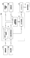
- FIG. 5 is a functional block diagram showing a configuration example of the external arithmetic device 30E.
- the external processing device 30E receives the outputs of the communication device M1, the positioning device M2, and the posture detection device M3, executes various calculations, and outputs the calculation results to the controller 30.
- the controller 30 outputs, for example, a control command according to the calculation result to the operation limiting unit E1.
- the operation restriction unit E1 is a functional element for restricting the movement of the shovel, and is, for example, a pressure reducing valve that adjusts a pilot pressure, or a switching valve that can shut off the flow of hydraulic fluid from the main pump 14 to the control valve 17 including.
- the switching valve 50 is employed as the operation limiting unit E1.
- the operation limiting unit E1 may include a warning output device that outputs a warning to the operator of the shovel.
- the warning output device is, for example, an audio output device or a warning lamp.
- the external arithmetic unit 30E mainly includes a terrain database update unit 31, a position coordinate update unit 32, a ground shape information acquisition unit 33, and a travel restriction unit 34.
- the terrain database update unit 31 is a functional element that updates a terrain database that systematically stores the terrain information of the work site so as to be referable.
- the terrain database updating unit 31 acquires terrain information of the work site through the communication device M1, for example, when the shovel is activated, and updates the terrain database.
- the topography database is stored in a non-volatile memory or the like. Terrain information of the work site is described, for example, by a three-dimensional terrain model based on the world positioning system.
- the position coordinate updating unit 32 is a functional element that updates the coordinates and the direction representing the current position of the shovel.
- the position coordinate updating unit 32 acquires the position coordinates and direction of the shovel in the world positioning system based on the output of the positioning device M2, and coordinates indicating the current position of the shovel stored in the non-volatile memory or the like. And update data on orientation.
- the position coordinate updating unit 32 may acquire the position coordinate and the direction of the shovel based on dead reckoning using an output of a gyro sensor, an acceleration sensor or the like.
- the ground shape information acquisition unit 33 is a functional element that acquires information on the current shape of the work target ground.
- the ground shape information acquisition unit 33 detects the terrain information updated by the terrain database update unit 31, the coordinates and direction indicating the current position of the shovel updated by the position coordinate update unit 32, and the posture detection device M3.
- Information on the current shape of the work target ground is acquired based on the past transition (operation history) of the posture of the excavation attachment. Therefore, the ground shape information acquisition unit 33 can acquire information on the change of the topography around the upper swing body 3 including the information on the change of the topography due to the excavation work.
- the operation history which is the transition of the posture of the excavation attachment, is, for example, boom angle ⁇ 1, arm angle ⁇ 2, bucket angle ⁇ 3, tilt angle ⁇ 4 around the Y axis of the shovel, tilt angle ⁇ 5 around the X axis of the shovel, etc. And at least one of the time series data stored in the volatile memory or the non-volatile memory.
- the ground shape information acquisition unit 33 may delete the operation history up to that point.
- the ground shape information acquisition unit 33 is based on the coordinates and direction indicating the current position of the shovel updated by the position coordinate update unit 32, and the past transition (operation history) of the posture of the excavation attachment detected by the posture detection device M3. Information on the current shape of the work target ground may be obtained.
- the travel limiting unit 34 is a functional element that limits travel of the shovel.
- the travel limiting unit 34 coordinates and indicates the current position of the shovel updated by the position coordinate updating unit 32, and information on the current shape of the work target ground acquired by the ground shape information acquisition unit 33.
- the movement of the undercarriage 1 is limited based on For example, when it is determined that the predetermined feature is present within a predetermined distance in the forward direction of the lower traveling body 1, the travel limiting unit 34 limits the forward movement of the lower traveling body 1 and the backward traveling direction of the lower traveling body 1 When it is determined that the predetermined feature is present within the predetermined distance, the reverse traveling of the lower traveling body 1 is limited.
- the predetermined feature is, for example, a feature that satisfies a predetermined condition among features such as a hole or a fill formed by an excavation operation.
- the predetermined feature is a hole having a depth greater than a predetermined depth, a hole having an inclination angle of a side surface (inclined surface) larger than a predetermined angle, an embankment having a height greater than a predetermined height, and an inclination angle of a side surface (inclined surface) Includes larger embankments etc.
- the posture of the shovel becomes extremely unstable if the lower traveling body 1 passes a predetermined feature.
- the forward direction and reverse direction of the undercarriage 1 are determined, for example, based on the output of the positioning device M2.
- the travel limiting unit 34 excludes holes having a side surface inclination angle of a predetermined angle or more as a predetermined feature and a hole whose inclination angle is less than a predetermined angle from the predetermined feature Do.
- a hole whose depth is equal to or greater than a predetermined depth may be set as a predetermined feature, and a hole whose depth is less than the predetermined depth may be excluded from the predetermined feature.
- the travel limiting unit 34 sets, for example, an embankment with an inclination angle of a side surface of a predetermined angle or more among the embankments formed in the excavation work as a predetermined feature, and an embankment with an inclination angle of less than the predetermined angle Exclude from things.
- the embankment whose height is equal to or more than a predetermined height may be set as a predetermined feature, and the embankment whose height is less than a predetermined height may be excluded from the predetermined features.
- the travel limitation of the shovel includes at least one of the limitation of the maximum moving speed of the undercarriage 1, the limitation of the maximum moving acceleration, the limitation of the maximum moving distance, and the prohibition of the movement.
- the travel limiting unit 34 when it is determined that the predetermined feature is present within the predetermined distance in the forward direction of the lower traveling body 1, the travel limiting unit 34 outputs the determination result to the controller 30.
- the controller 30 receiving the determination result outputs a shutoff command to the switching valve 50 as the operation limiting unit E1.
- the switching valve 50 that has received the shutoff command shuts off the communication between the traveling operation device as the operation device 26 and the right pilot port of each of the flow control valve 171 and the flow control valve 172 to inhibit the forward movement of the shovel.
- the travel operation device includes a travel lever and a travel pedal.
- the upper limit of the pilot pressure acting on the right pilot port of each of the flow control valve 171 and the flow control valve 172 may be lowered to limit the maximum forward speed.
- the forward movement of the shovel may be stopped when the distance to the predetermined feature becomes less than the predetermined value.
- the controller 30 may output a command to the motor regulator as the operation limiting unit E1, and may limit the moving speed of the lower traveling body 1 by fixing the traveling mode of the traveling hydraulic motor to the low speed traveling mode.
- the lower traveling body 1 includes a left crawler and a right crawler.
- the controller 30 may simultaneously restrict the movement of the left crawler and the right crawler, or may individually restrict them.
- the controller 30 can prevent the shovel from being stuck in the hole as the predetermined feature or running on the fill as the predetermined feature due to the operator's erroneous operation.
- the operator's erroneous operation includes a reverse operation performed with the intention to move the lower traveling body 1 forward and an advancing operation performed with the intention to move the lower traveling body 1 backward.
- the external calculation device 30E of FIG. 6 is different from the external calculation device 30E of FIG. 5 in that the ground shape information acquisition unit 33 can acquire information on the current shape of the work ground based on the output of the imaging device M5. , In all other respects. Therefore, the description of the common parts is omitted, and the different parts will be described in detail.
- the imaging device M5 may be attached to the excavation attachment or may be attached to the cabin 10. This is in order to be able to take an image of the surrounding terrain by turning along with the turning of the upper turning body 3.
- the imaging device M5 may be attached to a pole or the like installed at a work site, or may be attached to a flying object flying around the shovel.
- the flying object includes, for example, a multicopter or an airship.
- the ground shape information acquisition unit 33 can acquire information related to the current shape of the work target ground based on the distance image output by the imaging device M5, which is, for example, a stereo camera or a distance image camera.
- the imaging device M5 is attached to the excavation attachment
- the distance image is converted into a distance image based on the positioning device M2 (excavator) based on the relative positional relationship between the positioning device M2 and the imaging device M5.
- the imaging device M5 is attached to the pole
- the distance image is converted into a distance image based on the positioning device M2 (excavator) based on the previously measured attachment position (latitude, longitude, altitude) of the imaging device M5 Be done.
- the distance image is a distance image based on the output of the positioning device mounted on the flying object and the output of the positioning device M2 based on the positioning device M2 (excavator) Converted to
- the ground shape information acquisition unit 33 acquires information on the current shape of the work target ground based on the output of a distance measuring device which is a device for acquiring the surface state of a feature such as a lidar or a laser range finder. Good.
- the distance measuring device may be attached to the digging attachment as in the case of the imaging device M5, or may be attached to a pole or the like installed at the work site, and an aircraft flying around the shovel It may be attached to The conversion from the distance information measured by the distance measuring device to the distance information based on the shovel is performed in the same manner as described above.
- the imaging device M5 may be independent of the shovel.
- the controller 30 may acquire terrain information output by the imaging device M5 via the communication device M1.
- the imaging device M5 is attached to a multi-copter for aerial photography or a steel tower installed at a work site, and acquires topographical information of the work site based on an image of the work site viewed from above Good.
- the imaging device M5 may be an imaging device M5 provided in another shovel.
- the imaging device M5 may transmit data directly to the shovel, or may transmit data to the shovel via the management device.
- the management apparatus is, for example, a computer installed in an external facility such as a management center.
- the terrain database updating unit 31 acquires terrain information from the external imaging device M5 or terrain information from the management device through the communication device M1. . Then, the terrain database updating unit 31 updates the terrain information around the shovel based on the acquired terrain information, and the ground shape information acquiring unit 33 changes the terrain based on the terrain information updated by the terrain database updating unit 31. You can get information about
- the controller 30 can more reliably prevent the shovel from being stuck in the hole as the predetermined feature or running on the fill as the predetermined feature due to the operator's erroneous operation.
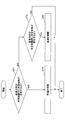
- FIG. 7 is a flowchart of the travel restriction process.
- the controller 30 repeatedly executes this traveling restriction process at a predetermined control cycle.
- the ground shape information acquisition unit 33 of the controller 30 acquires information on the current shape of the work target ground in parallel with the travel restriction process.
- the ground shape information acquisition unit 33 detects the terrain information updated by the terrain database update unit 31, the coordinates and direction indicating the current position of the shovel updated by the position coordinate update unit 32, and the posture detection device M3.
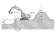
- FIGS. 8A-8C are cross-sectional views of the work target ground, showing how the shapes change in the order of FIG. 8A, FIG. 8B and FIG. 8C.
- the dashed-dotted line in each of FIGS. 8A-8C represents the target topography (the topography to be realized by the digging operation).
- the shovel acquires data on the target topography through the communication device M1.
- the travel limiting unit 34 of the controller 30 determines whether a predetermined feature exists within a predetermined distance in the forward direction (step ST1).
- the predetermined feature is a hole having a depth greater than the predetermined depth TH1 and a side inclination angle greater than the predetermined angle TH2, and a height higher than the predetermined height TH3, and an inclination angle of the side greater than the predetermined angle TH4. Includes large fill.
- the travel limiting unit 34 grasps the shape of the predetermined feature and the distance to the predetermined feature, and determines whether or not the predetermined feature is present within the predetermined distance in the forward direction.
- the predetermined distance in the forward direction is, for example, the horizontal distance from the front end of the undercarriage 1.
- the travel limiting unit 34 limits the forward (step ST2).
- the travel limiting unit 34 determines whether the predetermined feature is present within the predetermined distance in the reverse direction (Ste ST3).
- the travel limiting unit 34 limits the reverse (step ST4).
- the predetermined distance in the reverse direction is, for example, the horizontal distance from the rear end of the lower traveling body 1.
- the travel limiting unit 34 Ends the current travel restriction process without restricting either forward or reverse.
- the travel limiting unit 34 determines that the predetermined feature does not exist within the predetermined distance in the forward direction, and then determines whether the predetermined feature exists within the predetermined distance in the reverse direction. There is. However, after determining that the predetermined feature does not exist within the predetermined distance in the reverse direction, the travel limiting unit 34 may determine whether the predetermined feature exists within the predetermined distance in the forward direction. Alternatively, two determinations may be performed in parallel.
- the travel restriction unit 34 has predetermined features in the forward direction. It determines that it does not exist.
- This hole has a side surface with an inclination angle ⁇ 1 larger than the predetermined angle TH2, but is not determined to be the predetermined feature because the depth D1 is less than the predetermined depth TH1. Therefore, the travel limiting unit 34 does not limit the forward travel.
- the hole having the depth D1 may be determined to be a predetermined feature because it has a side surface having an inclination angle ⁇ 1 larger than the predetermined angle TH2. In this case, the travel limiting unit 34 limits the forward travel.
- the travel limiting unit 34 determines that the predetermined feature does not exist in the reverse direction. .
- this embankment has the side surface of inclination angle ⁇ 1 larger than predetermined angle TH4, since height H1 is less than predetermined height TH3, it is not determined as a predetermined feature. Therefore, the travel limiting unit 34 does not limit reverse travel.
- the embankment of the height H1 may be determined to be a predetermined feature because it has a side surface of the inclination angle ⁇ 1 larger than the predetermined angle TH4. In this case, the travel limiting unit 34 limits reverse travel.
- the travel limiting unit 34 determines that the predetermined feature does not exist in the forward direction. Further, within the predetermined distance R in the reverse direction, the embankment continuing to the height H2 which is the predetermined height TH3 or more exists, but since the inclination angle ⁇ 2 of the side is less than the predetermined angle TH4, the travel limiting portion 34 It is determined that a predetermined feature does not exist behind. Therefore, the travel limiting unit 34 does not limit either forward or reverse.
- the travel limiting unit 34 may determine that the hole existing in the predetermined distance F in the forward direction is the predetermined feature because the hole continues to the depth D2. Also, the embankment may be determined as the predetermined feature because the embankment existing within the predetermined distance R in the reverse direction continues up to the height H2.
- the ground shape information acquisition unit 33 sets a range of a distance L equal to the depth D3 of the hole from the edge of the hole determined to be a predetermined feature as the limit range, and travels the lower part so that the shovel does not enter the limit range.
- the movement of the body 1 may be restricted.
- the ground shape information acquisition unit 33 can suppress the approach of the shovel from the predetermined feature and can further enhance the safety.
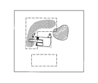
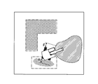
- FIGS. 9A to 9C are top views of the work site, showing how the digging operation proceeds in the order of FIGS. 9A, 9B and 9C.
- the dashed dotted line in each of FIGS. 9A to 9C represents the position of the hole that constitutes the target topography.
- the dot pattern represents the position of a hole as a predetermined feature.
- the hatching pattern represents the position of the fill as a predetermined feature.
- FIG. 9A shows the state of the work site before the digging operation is performed.
- An alternate long and short dash line indicates that a hole is to be formed in two places.
- the travel limiting unit 34 does not limit traveling of the shovel.
- FIG. 9B shows the state of the work site when the shovel is digging the first hole of the two holes.
- the dot pattern represents that a hole as a predetermined feature is formed within the range corresponding to the first hole.
- the hatching pattern indicates that the earth and sand excavated to form the first hole has formed an embankment as a predetermined feature.
- the travel limiting unit 34 limits the forward movement of the shovel. This is because a hole as a predetermined feature exists within a predetermined distance F in the forward direction of the lower traveling body 1.
- the travel limiting unit 34 does not limit the reverse travel of the shovel. This is because the predetermined feature is not present within the predetermined distance R in the reverse traveling direction of the lower traveling body 1.
- FIG. 9C represents the state of the work site when the shovel is drilling a second hole after completing the formation of the first of the two holes.
- the dot pattern represents that a hole as a predetermined feature is formed in the range corresponding to the first hole and in the range corresponding to the second hole.
- the hatching pattern indicates that the earth and sand excavated to form the first hole and the second hole form a deposit as a predetermined feature.
- the travel limiting unit 34 limits the reverse travel of the shovel. This is because a hole (second hole) as a predetermined feature exists within a predetermined distance R in the reverse traveling direction of the lower traveling body 1.
- the travel limiting unit 34 does not limit the forward movement of the shovel. This is because the predetermined feature is not present within the predetermined distance F in the forward direction of the lower traveling body 1.
- the controller 30 restricts the movement of the undercarriage 1 when the predetermined feature is present within the predetermined distance in the movement direction. Therefore, it is possible to prevent the shovel from falling in the hole excavated by the shovel and preventing the shovel from riding on the embankment made by the shovel.
- This limitation is particularly effective in a situation where the operator causes the undercarriage 1 to move in the opposite direction to the intended direction. Such a situation occurs, for example, when the operator concentrates too much on the operation of the attachment and misinterprets the forward direction of the lower traveling vehicle 1 as the reverse direction. However, it is also effective when the operator advances the lower traveling body 1 in the intended direction. This is because the predetermined features such as the holes and the fillings are difficult to see from the cabin 10, and it is difficult for the operator to notice the existence or to easily forget the existence.
- the shovel according to the embodiment of the present invention is configured such that the controller 30 restricts the movement of the lower traveling body 1 based on the information on the topography of the upper swing body 3.
- the shovel is configured such that the controller 30 restricts the movement of the undercarriage 1 based on the information on the change in topography around the upper swing body 3. Therefore, the shovel according to the embodiment of the present invention is, for example, stuck in a hole excavated by its own machine or another machine, or runs over an embankment made by its own machine or another machine, resulting in an unstable state of its own machine. Can be prevented in advance.
- the controller 30 desirably limits the movement of the undercarriage 1 based on the information on the change in topography due to the digging operation.
- the movement of the undercarriage 1 is limited based on the information on the change in topography due to the excavation work of the own aircraft. Therefore, the shovel mounted with the controller 30 can prevent the self-machine from becoming unstable due to being stuck in the hole excavated by the self-machine or riding on the embankment made by the self-machine.
- the controller 30 desirably acquires information on the change in topography due to the digging operation based on the operation history of the attachment including the detection value of the posture detection device M3. Therefore, the shovel mounted with the controller 30 can reliably and accurately acquire information on a hole excavated by the own machine, information on a deposit made by the own machine, and the like.
- the controller 30 is an upper part based on an output of a device (for example, an imaging device M5 or a distance measuring device) for acquiring the surface state of a feature or a device (for example, a posture detection device M3) for acquiring a locus of movement of an attachment.
- a device for example, an imaging device M5 or a distance measuring device
- a device for example, a posture detection device M3
- a device for example, an imaging device M5 or a distance measuring device for acquiring the surface state of a feature or a device (for example, a posture detection device M3) for acquiring a locus of movement of an attachment is desirably attached to the attachment There is. Therefore, a device (for example, an imaging device M5 or a distance measuring device) for acquiring the surface state of a feature or a device for acquiring a locus of movement of an attachment (for example, a posture detection device M3) Since the imaging direction or the measurement direction or the digging position changes according to, surrounding terrain can be imaged or measured over a wide range or can be derived.
- the undercarriage 1 is typically driven by a variable displacement hydraulic motor.
- the controller 30 can restrict the movement of the lower traveling body 1 by fixing the traveling mode of the hydraulic motor to the low speed traveling mode, that is, by not switching to the high speed traveling mode. Therefore, the controller 30 can restrict the movement of the undercarriage 1 simply and quickly.
- the controller 30 desirably limits at least one of the moving direction and the moving speed of the undercarriage 1. Therefore, the controller 30 can prevent the lower traveling body 1 from invading the predetermined feature without restricting the movement of the lower traveling body 1 in the direction away from the predetermined feature.
- the controller 30 may set a range of a predetermined distance from the predetermined feature as the limit range. With this configuration, the controller 30 can more reliably prevent the shovel from approaching the predetermined feature, and can further enhance the safety.
- the controller 30 may be configured to acquire information on the topography of the periphery of the upper swing body 3 from the imaging device M5 outside the shovel. With this configuration, the controller 30 can more easily acquire the work site terrain information.
- the external computing device 30E may be integrated into the controller 30. Further, the external computing device 30E may not be mounted on a shovel.
- the external computing device 30E may be provided in an external management facility such as a management center.
- the external computing device 30E may receive data acquired by at least one of the positioning device M2, the posture detection device M3, the imaging device M5, etc. via the network, and may calculate information related to topography, such as finished information . And you may transmit the information regarding the calculated topography to a shovel.
- the shovel may limit the movement of the undercarriage 1 based on the received information on the topography.
- the data acquired by the positioning device and the imaging device mounted on the aircraft may be transmitted from the aircraft to the external computing device E.
- the external computing device E may calculate information on the terrain based on the received data, and transmit the information on the terrain to the shovel.
- the vehicle may calculate the information on the terrain and transmit the information on the terrain directly to the shovel.
- Communication device M2 ... Positioning device M3 ... Posture detection device M3 a ... Boom angle sensor M3 b ... Arm angle sensor M3 c Bucket angle sensor M3d ⁇ ⁇ ⁇ vehicle body inclination sensor M5 ⁇ ⁇ ⁇ imaging apparatus
Landscapes
- Engineering & Computer Science (AREA)
- Mining & Mineral Resources (AREA)
- Civil Engineering (AREA)
- General Engineering & Computer Science (AREA)
- Structural Engineering (AREA)
- Mechanical Engineering (AREA)
- Operation Control Of Excavators (AREA)
- Component Parts Of Construction Machinery (AREA)
Abstract
L'excavatrice décrite par la présente invention comprend un corps mobile inférieur (1), un corps rotatif supérieur (3) qui est monté sur le corps mobile inférieur (1) et comprend un accessoire et un dispositif de commande (30) qui est monté sur le corps rotatif supérieur (3). Le dispositif de commande (30) limite le mouvement du corps mobile inférieur (1) sur la base d'informations relatives à des changements de la topographie autour du corps rotatif supérieur (3). Le dispositif de commande (30) limite par exemple le mouvement du corps mobile inférieur (1) sur la base d'informations relatives à la topographie provoquées par le travail d'excavation.
Priority Applications (3)
| Application Number | Priority Date | Filing Date | Title |
|---|---|---|---|
| CN201880050344.XA CN110998032A (zh) | 2017-07-31 | 2018-07-27 | 挖土机 |
| JP2019534473A JP7507559B2 (ja) | 2017-07-31 | 2018-07-27 | ショベル及びショベルの制御方法 |
| US16/775,389 US12031302B2 (en) | 2017-07-31 | 2020-01-29 | Excavator |
Applications Claiming Priority (2)
| Application Number | Priority Date | Filing Date | Title |
|---|---|---|---|
| JP2017-147669 | 2017-07-31 | ||
| JP2017147669 | 2017-07-31 |
Related Child Applications (1)
| Application Number | Title | Priority Date | Filing Date |
|---|---|---|---|
| US16/775,389 Continuation US12031302B2 (en) | 2017-07-31 | 2020-01-29 | Excavator |
Publications (1)
| Publication Number | Publication Date |
|---|---|
| WO2019026802A1 true WO2019026802A1 (fr) | 2019-02-07 |
Family
ID=65233902
Family Applications (1)
| Application Number | Title | Priority Date | Filing Date |
|---|---|---|---|
| PCT/JP2018/028304 Ceased WO2019026802A1 (fr) | 2017-07-31 | 2018-07-27 | Excavatrice |
Country Status (4)
| Country | Link |
|---|---|
| US (1) | US12031302B2 (fr) |
| JP (1) | JP7507559B2 (fr) |
| CN (1) | CN110998032A (fr) |
| WO (1) | WO2019026802A1 (fr) |
Cited By (13)
| Publication number | Priority date | Publication date | Assignee | Title |
|---|---|---|---|---|
| WO2020166241A1 (fr) * | 2019-02-14 | 2020-08-20 | コベルコ建機株式会社 | Dispositif de surveillance et engin de chantier |
| JP2020159142A (ja) * | 2019-03-27 | 2020-10-01 | 日立建機株式会社 | 作業機械 |
| WO2020229277A1 (fr) * | 2019-05-16 | 2020-11-19 | Robert Bosch Gmbh | Procédé pour déposer un outil d'un engin de construction |
| US20220010521A1 (en) * | 2019-03-28 | 2022-01-13 | Sumitomo Construction Machinery Co., Ltd. | Shovel and construction system |
| JP2022026596A (ja) * | 2020-07-31 | 2022-02-10 | 日立建機株式会社 | 作業機械および施工支援システム |
| KR20220048084A (ko) * | 2020-10-12 | 2022-04-19 | 현대두산인프라코어(주) | 건설장비의 능동형 험지 이동 시스템 및 그 방법 |
| JP7191183B1 (ja) | 2021-11-05 | 2022-12-16 | 日立建機株式会社 | 作業機械 |
| JP2023047506A (ja) * | 2021-09-27 | 2023-04-06 | ヤンマーホールディングス株式会社 | 作業機械用制御システム、作業機械、作業機械の制御方法及び作業機械用制御プログラム |
| WO2023132321A1 (fr) * | 2022-01-06 | 2023-07-13 | 住友重機械工業株式会社 | Système de surveillance de zone environnante et engin de chantier |
| JP2023133701A (ja) * | 2022-03-14 | 2023-09-27 | 日立建機株式会社 | 作業機械 |
| WO2025126682A1 (fr) * | 2023-12-15 | 2025-06-19 | 川崎重工業株式会社 | Système de reconnaissance de terrain et procédé de reconnaissance de terrain |
| WO2025204157A1 (fr) * | 2024-03-26 | 2025-10-02 | 株式会社小松製作所 | Système d'affichage pour engin de chantier, engin de chantier et procédé d'affichage pour engin de chantier |
| WO2026034023A1 (fr) * | 2024-08-07 | 2026-02-12 | 株式会社小松製作所 | Système de commande d'engin de chantier, engin de chantier, système d'actionnement à distance d'engin de chantier, et procédé de commande d'engin de chantier |
Families Citing this family (7)
| Publication number | Priority date | Publication date | Assignee | Title |
|---|---|---|---|---|
| JP6634363B2 (ja) * | 2016-11-16 | 2020-01-22 | 日立建機株式会社 | 作業機械 |
| JP7418948B2 (ja) * | 2018-03-28 | 2024-01-22 | 株式会社小松製作所 | 作業車両の制御システム、方法、及び作業車両 |
| JP7188941B2 (ja) * | 2018-08-31 | 2022-12-13 | 株式会社小松製作所 | 作業機械の制御装置および制御方法 |
| JP7149205B2 (ja) * | 2019-03-05 | 2022-10-06 | 日立建機株式会社 | 自動運転作業機械 |
| CN112180928B (zh) * | 2020-09-30 | 2023-01-31 | 上海三一重机股份有限公司 | 挖掘机控制方法、挖掘机控制装置及挖掘机 |
| CN113879979A (zh) * | 2021-08-05 | 2022-01-04 | 国家石油天然气管网集团有限公司 | 一种液压挖掘机吊管设备作业防倾翻监测装置及方法 |
| JP2023169512A (ja) | 2022-05-17 | 2023-11-30 | キヤノン株式会社 | 監視システム、監視システムの制御方法およびプログラム |
Citations (3)
| Publication number | Priority date | Publication date | Assignee | Title |
|---|---|---|---|---|
| JP2014006577A (ja) * | 2012-06-21 | 2014-01-16 | Hitachi Constr Mach Co Ltd | 運搬機械の停止位置判定装置およびこの装置を備えた積込機械 |
| JP2016172963A (ja) * | 2015-03-16 | 2016-09-29 | 住友重機械工業株式会社 | ショベル |
| JP2017014726A (ja) * | 2015-06-29 | 2017-01-19 | 日立建機株式会社 | 作業機械の作業支援システム |
Family Cites Families (43)
| Publication number | Priority date | Publication date | Assignee | Title |
|---|---|---|---|---|
| US4465155A (en) * | 1981-06-17 | 1984-08-14 | Collins Marshall S | Automated operatorless vehicles |
| US5720354A (en) * | 1996-01-11 | 1998-02-24 | Vermeer Manufacturing Company | Trenchless underground boring system with boring tool location |
| JP3745484B2 (ja) * | 1997-02-12 | 2006-02-15 | 株式会社小松製作所 | 車両の監視装置 |
| IT1291804B1 (it) * | 1997-03-17 | 1999-01-21 | Miro Cesare Mati | Attrezzatura per la lavorazione di un terreno senza escavazioni demolitive |
| US6252544B1 (en) * | 1998-01-27 | 2001-06-26 | Steven M. Hoffberg | Mobile communication device |
| JPH11222882A (ja) | 1998-02-05 | 1999-08-17 | Komatsu Ltd | 危険領域監視装置 |
| US6363632B1 (en) * | 1998-10-09 | 2002-04-02 | Carnegie Mellon University | System for autonomous excavation and truck loading |
| EP1083076A3 (fr) * | 1999-09-07 | 2005-01-12 | Mazda Motor Corporation | Dispositif afficheur pour véhicule |
| SE526913C2 (sv) * | 2003-01-02 | 2005-11-15 | Arnex Navigation Systems Ab | Förfarande i form av intelligenta funktioner för fordon och automatiska lastmaskiner gällande kartläggning av terräng och materialvolymer, hinderdetektering och styrning av fordon och arbetsredskap |
| JP4436647B2 (ja) * | 2003-09-30 | 2010-03-24 | 日立建機株式会社 | 油圧駆動車両の走行制御装置および油圧駆動車両 |
| US7197871B2 (en) * | 2003-11-14 | 2007-04-03 | Caterpillar Inc | Power system and work machine using same |
| US8364366B2 (en) * | 2005-06-24 | 2013-01-29 | Deere & Company | System and method for providing a safety zone associated with a vehicle |
| US7344465B2 (en) * | 2005-07-28 | 2008-03-18 | Caterpillar Inc. | Drive system for a machine |
| US8315789B2 (en) * | 2007-03-21 | 2012-11-20 | Commonwealth Scientific And Industrial Research Organisation | Method for planning and executing obstacle-free paths for rotating excavation machinery |
| US20090259399A1 (en) * | 2008-04-15 | 2009-10-15 | Caterpillar Inc. | Obstacle detection method and system |
| US8170787B2 (en) * | 2008-04-15 | 2012-05-01 | Caterpillar Inc. | Vehicle collision avoidance system |
| JP5476687B2 (ja) * | 2008-07-24 | 2014-04-23 | 株式会社デンソー | 車両用表示装置 |
| JP5269026B2 (ja) * | 2010-09-29 | 2013-08-21 | 日立建機株式会社 | 作業機械の周囲監視装置 |
| AU2011334609A1 (en) * | 2010-11-25 | 2013-06-27 | Technological Resources Pty. Limited | Apparatus and method for obtaining information from drilled holes for mining |
| US8688332B2 (en) * | 2011-04-20 | 2014-04-01 | Caterpillar Inc. | Management system incorporating performance and detection data |
| AU2012268476B2 (en) * | 2011-06-07 | 2014-05-15 | Komatsu Ltd. | Perimeter monitoring device for work vehicle |
| JP5750344B2 (ja) * | 2011-09-16 | 2015-07-22 | 日立建機株式会社 | 作業機の周囲監視装置 |
| CA2849383C (fr) * | 2013-08-20 | 2016-06-07 | Yasunori Kimura | Controleur de machine de construction |
| EP3041227A4 (fr) * | 2013-08-26 | 2017-05-24 | Hitachi Construction Machinery Co., Ltd. | Dispositif pour surveiller une zone autour d'un engin de chantier |
| CN104563190A (zh) * | 2013-10-24 | 2015-04-29 | 西安众智惠泽光电科技有限公司 | 一种挖掘机监控系统 |
| CN105297817A (zh) * | 2014-07-28 | 2016-02-03 | 西安众智惠泽光电科技有限公司 | 一种对挖掘机进行监控的方法 |
| CN105971050A (zh) * | 2015-03-13 | 2016-09-28 | 住友重机械工业株式会社 | 挖掘机 |
| JPWO2015125979A1 (ja) * | 2015-04-28 | 2018-02-15 | 株式会社小松製作所 | 作業機械の周辺監視装置及び作業機械の周辺監視方法 |
| EP3343171B1 (fr) | 2015-08-26 | 2024-01-17 | Sumitomo (S.H.I.) Construction Machinery Co., Ltd. | Dispositif de mesure pour une pelleteuse |
| DE102015221340B4 (de) * | 2015-10-30 | 2021-02-25 | Conti Temic Microelectronic Gmbh | Vorrichtung und Verfahren zur Bereitstellung einer Fahrzeugumgebungsansicht für ein Fahrzeug |
| US20170307362A1 (en) * | 2016-04-22 | 2017-10-26 | Caterpillar Inc. | System and method for environment recognition |
| US9827678B1 (en) * | 2016-05-16 | 2017-11-28 | X Development Llc | Kinematic design for robotic arm |
| US9827677B1 (en) * | 2016-05-16 | 2017-11-28 | X Development Llc | Robotic device with coordinated sweeping tool and shovel tool |
| JP6729146B2 (ja) * | 2016-08-03 | 2020-07-22 | コベルコ建機株式会社 | 障害物検出装置 |
| JP6805883B2 (ja) * | 2017-02-28 | 2020-12-23 | コベルコ建機株式会社 | 建設機械 |
| JP6760163B2 (ja) * | 2017-03-22 | 2020-09-23 | コベルコ建機株式会社 | 建設機械 |
| JP6819462B2 (ja) * | 2017-05-30 | 2021-01-27 | コベルコ建機株式会社 | 作業機械 |
| US10761537B1 (en) * | 2017-06-02 | 2020-09-01 | Built Robotics Inc. | Obstacle detection and manipulation by a vehicle within a dig site |
| JP6589945B2 (ja) * | 2017-07-14 | 2019-10-16 | コベルコ建機株式会社 | 建設機械 |
| EP3730700B1 (fr) * | 2017-12-21 | 2024-05-22 | Sumitomo (S.H.I.) Construction Machinery Co., Ltd. | Pelle et procédé de gestion de pelle |
| JP6900897B2 (ja) * | 2017-12-25 | 2021-07-07 | コベルコ建機株式会社 | 建設機械の障害物検出装置 |
| WO2021010489A1 (fr) * | 2019-07-17 | 2021-01-21 | 住友建機株式会社 | Engin de chantier et dispositif d'assistance qui aide au travail à l'aide d'un engin de chantier |
| KR102803168B1 (ko) * | 2020-03-27 | 2025-04-30 | 스미도모쥬기가이고교 가부시키가이샤 | 작업기계용 정보처리장치, 정보관리시스템, 작업기계용 정보처리프로그램을 저장한 기억장치 |
-
2018
- 2018-07-27 WO PCT/JP2018/028304 patent/WO2019026802A1/fr not_active Ceased
- 2018-07-27 JP JP2019534473A patent/JP7507559B2/ja active Active
- 2018-07-27 CN CN201880050344.XA patent/CN110998032A/zh active Pending
-
2020
- 2020-01-29 US US16/775,389 patent/US12031302B2/en active Active
Patent Citations (3)
| Publication number | Priority date | Publication date | Assignee | Title |
|---|---|---|---|---|
| JP2014006577A (ja) * | 2012-06-21 | 2014-01-16 | Hitachi Constr Mach Co Ltd | 運搬機械の停止位置判定装置およびこの装置を備えた積込機械 |
| JP2016172963A (ja) * | 2015-03-16 | 2016-09-29 | 住友重機械工業株式会社 | ショベル |
| JP2017014726A (ja) * | 2015-06-29 | 2017-01-19 | 日立建機株式会社 | 作業機械の作業支援システム |
Cited By (24)
| Publication number | Priority date | Publication date | Assignee | Title |
|---|---|---|---|---|
| CN113439144A (zh) * | 2019-02-14 | 2021-09-24 | 神钢建机株式会社 | 监控装置以及工程机械 |
| WO2020166241A1 (fr) * | 2019-02-14 | 2020-08-20 | コベルコ建機株式会社 | Dispositif de surveillance et engin de chantier |
| EP3907336A4 (fr) * | 2019-02-14 | 2022-03-23 | Kobelco Construction Machinery Co., Ltd. | Dispositif de surveillance et engin de chantier |
| JP7003082B2 (ja) | 2019-03-27 | 2022-01-20 | 日立建機株式会社 | 作業機械 |
| JP2020159142A (ja) * | 2019-03-27 | 2020-10-01 | 日立建機株式会社 | 作業機械 |
| US20220010521A1 (en) * | 2019-03-28 | 2022-01-13 | Sumitomo Construction Machinery Co., Ltd. | Shovel and construction system |
| CN113795635A (zh) * | 2019-05-16 | 2021-12-14 | 罗伯特·博世有限公司 | 用于对工程机器的工具进行放置的方法 |
| WO2020229277A1 (fr) * | 2019-05-16 | 2020-11-19 | Robert Bosch Gmbh | Procédé pour déposer un outil d'un engin de construction |
| JP7390991B2 (ja) | 2020-07-31 | 2023-12-04 | 日立建機株式会社 | 作業機械および施工支援システム |
| JP2022026596A (ja) * | 2020-07-31 | 2022-02-10 | 日立建機株式会社 | 作業機械および施工支援システム |
| KR20220048084A (ko) * | 2020-10-12 | 2022-04-19 | 현대두산인프라코어(주) | 건설장비의 능동형 험지 이동 시스템 및 그 방법 |
| KR102897996B1 (ko) * | 2020-10-12 | 2025-12-08 | 에이치디현대인프라코어 주식회사 | 건설장비의 능동형 험지 이동 시스템 및 그 방법 |
| JP2023047506A (ja) * | 2021-09-27 | 2023-04-06 | ヤンマーホールディングス株式会社 | 作業機械用制御システム、作業機械、作業機械の制御方法及び作業機械用制御プログラム |
| JP7667050B2 (ja) | 2021-09-27 | 2025-04-22 | ヤンマーホールディングス株式会社 | 作業機械用制御システム、作業機械、作業機械の制御方法及び作業機械用制御プログラム |
| WO2023080114A1 (fr) * | 2021-11-05 | 2023-05-11 | 日立建機株式会社 | Engin de chantier |
| JP2023069275A (ja) * | 2021-11-05 | 2023-05-18 | 日立建機株式会社 | 作業機械 |
| JP7191183B1 (ja) | 2021-11-05 | 2022-12-16 | 日立建機株式会社 | 作業機械 |
| WO2023132321A1 (fr) * | 2022-01-06 | 2023-07-13 | 住友重機械工業株式会社 | Système de surveillance de zone environnante et engin de chantier |
| US12522143B2 (en) | 2022-01-06 | 2026-01-13 | Sumitomo Heavy Industries, Ltd. | Surround view monitor system, and work machine |
| JP2023133701A (ja) * | 2022-03-14 | 2023-09-27 | 日立建機株式会社 | 作業機械 |
| JP7737330B2 (ja) | 2022-03-14 | 2025-09-10 | 日立建機株式会社 | 作業機械 |
| WO2025126682A1 (fr) * | 2023-12-15 | 2025-06-19 | 川崎重工業株式会社 | Système de reconnaissance de terrain et procédé de reconnaissance de terrain |
| WO2025204157A1 (fr) * | 2024-03-26 | 2025-10-02 | 株式会社小松製作所 | Système d'affichage pour engin de chantier, engin de chantier et procédé d'affichage pour engin de chantier |
| WO2026034023A1 (fr) * | 2024-08-07 | 2026-02-12 | 株式会社小松製作所 | Système de commande d'engin de chantier, engin de chantier, système d'actionnement à distance d'engin de chantier, et procédé de commande d'engin de chantier |
Also Published As
| Publication number | Publication date |
|---|---|
| US20200165799A1 (en) | 2020-05-28 |
| JPWO2019026802A1 (ja) | 2020-07-27 |
| JP7507559B2 (ja) | 2024-06-28 |
| CN110998032A (zh) | 2020-04-10 |
| US12031302B2 (en) | 2024-07-09 |
Similar Documents
| Publication | Publication Date | Title |
|---|---|---|
| JP7507559B2 (ja) | ショベル及びショベルの制御方法 | |
| JP7402736B2 (ja) | ショベル及びその制御方法 | |
| CN108431338B (zh) | 铲土机 | |
| JP6401087B2 (ja) | ショベル及びその制御方法 | |
| JP6672313B2 (ja) | ショベル | |
| KR101821470B1 (ko) | 굴삭 기계의 제어 시스템 및 굴삭 기계 | |
| JP6462435B2 (ja) | ショベル | |
| WO2019009341A1 (fr) | Pelle | |
| CN108699815A (zh) | 挖土机 | |
| CN105971050A (zh) | 挖掘机 | |
| CN107923745A (zh) | 挖土机的测量装置 | |
| JP7354312B2 (ja) | ショベル及びショベルの情報更新方法 | |
| CN103119225A (zh) | 推土铲控制系统及建筑机械 | |
| WO2019117166A1 (fr) | Pelleteuse | |
| JP2016169571A (ja) | ショベル | |
| JP7463158B2 (ja) | 作業管理システム | |
| JP6710442B2 (ja) | ショベル | |
| JP2023041850A (ja) | ショベル及びショベル用のシステム | |
| JP2019148166A (ja) | ショベル | |
| WO2019116855A1 (fr) | Procédé, système de commande d'engin de chantier et engin de chantier | |
| JP6928740B2 (ja) | 施工管理システム、作業機械、及び施工管理方法 |
Legal Events
| Date | Code | Title | Description |
|---|---|---|---|
| 121 | Ep: the epo has been informed by wipo that ep was designated in this application |
Ref document number: 18841223 Country of ref document: EP Kind code of ref document: A1 |
|
| ENP | Entry into the national phase |
Ref document number: 2019534473 Country of ref document: JP Kind code of ref document: A |
|
| NENP | Non-entry into the national phase |
Ref country code: DE |
|
| 122 | Ep: pct application non-entry in european phase |
Ref document number: 18841223 Country of ref document: EP Kind code of ref document: A1 |