WO2019030892A1 - Turbine pour turbocompresseur et turbocompresseur - Google Patents
Turbine pour turbocompresseur et turbocompresseur Download PDFInfo
- Publication number
- WO2019030892A1 WO2019030892A1 PCT/JP2017/029080 JP2017029080W WO2019030892A1 WO 2019030892 A1 WO2019030892 A1 WO 2019030892A1 JP 2017029080 W JP2017029080 W JP 2017029080W WO 2019030892 A1 WO2019030892 A1 WO 2019030892A1
- Authority
- WO
- WIPO (PCT)
- Prior art keywords
- turbine
- impeller
- turbine impeller
- convex portion
- tapered surface
- Prior art date
- Legal status (The legal status is an assumption and is not a legal conclusion. Google has not performed a legal analysis and makes no representation as to the accuracy of the status listed.)
- Ceased
Links
Images







Classifications
-
- F—MECHANICAL ENGINEERING; LIGHTING; HEATING; WEAPONS; BLASTING
- F01—MACHINES OR ENGINES IN GENERAL; ENGINE PLANTS IN GENERAL; STEAM ENGINES
- F01D—NON-POSITIVE DISPLACEMENT MACHINES OR ENGINES, e.g. STEAM TURBINES
- F01D25/00—Component parts, details, or accessories, not provided for in, or of interest apart from, other groups
- F01D25/24—Casings; Casing parts, e.g. diaphragms, casing fastenings
-
- F—MECHANICAL ENGINEERING; LIGHTING; HEATING; WEAPONS; BLASTING
- F04—POSITIVE - DISPLACEMENT MACHINES FOR LIQUIDS; PUMPS FOR LIQUIDS OR ELASTIC FLUIDS
- F04D—NON-POSITIVE-DISPLACEMENT PUMPS
- F04D29/00—Details, component parts, or accessories
- F04D29/40—Casings; Connections of working fluid
- F04D29/42—Casings; Connections of working fluid for radial or helico-centrifugal pumps
- F04D29/4206—Casings; Connections of working fluid for radial or helico-centrifugal pumps especially adapted for elastic fluid pumps
-
- F—MECHANICAL ENGINEERING; LIGHTING; HEATING; WEAPONS; BLASTING
- F01—MACHINES OR ENGINES IN GENERAL; ENGINE PLANTS IN GENERAL; STEAM ENGINES
- F01D—NON-POSITIVE DISPLACEMENT MACHINES OR ENGINES, e.g. STEAM TURBINES
- F01D17/00—Regulating or controlling by varying flow
- F01D17/10—Final actuators
- F01D17/12—Final actuators arranged in stator parts
- F01D17/14—Final actuators arranged in stator parts varying effective cross-sectional area of nozzles or guide conduits
-
- F—MECHANICAL ENGINEERING; LIGHTING; HEATING; WEAPONS; BLASTING
- F01—MACHINES OR ENGINES IN GENERAL; ENGINE PLANTS IN GENERAL; STEAM ENGINES
- F01D—NON-POSITIVE DISPLACEMENT MACHINES OR ENGINES, e.g. STEAM TURBINES
- F01D25/00—Component parts, details, or accessories, not provided for in, or of interest apart from, other groups
- F01D25/24—Casings; Casing parts, e.g. diaphragms, casing fastenings
- F01D25/246—Fastening of diaphragms or stator-rings
-
- F—MECHANICAL ENGINEERING; LIGHTING; HEATING; WEAPONS; BLASTING
- F02—COMBUSTION ENGINES; HOT-GAS OR COMBUSTION-PRODUCT ENGINE PLANTS
- F02B—INTERNAL-COMBUSTION PISTON ENGINES; COMBUSTION ENGINES IN GENERAL
- F02B33/00—Engines characterised by provision of pumps for charging or scavenging
- F02B33/32—Engines with pumps other than of reciprocating-piston type
- F02B33/34—Engines with pumps other than of reciprocating-piston type with rotary pumps
- F02B33/40—Engines with pumps other than of reciprocating-piston type with rotary pumps of non-positive-displacement type
-
- F—MECHANICAL ENGINEERING; LIGHTING; HEATING; WEAPONS; BLASTING
- F02—COMBUSTION ENGINES; HOT-GAS OR COMBUSTION-PRODUCT ENGINE PLANTS
- F02B—INTERNAL-COMBUSTION PISTON ENGINES; COMBUSTION ENGINES IN GENERAL
- F02B39/00—Component parts, details, or accessories relating to, driven charging or scavenging pumps, not provided for in groups F02B33/00 - F02B37/00
Definitions
- the present disclosure relates to a turbine for a turbocharger and a turbocharger.
- turbochargers that are driven by utilizing exhaust energy of marine and automobile internal combustion engines and increase the pressure of the internal combustion engine to increase the output of the internal combustion engine.
- Such a turbocharger comprises a compressor and a turbine arranged across a bearing casing.
- Patent Document 1 discloses a turbocharger in which a compressor impeller and a turbine impeller are connected to each other by a rotating shaft supported by a bearing.
- the compressor impeller tends to be larger in diameter than the turbine impeller.
- the thrust force acting on the back surface of the compressor impeller force generated in the direction from the turbine toward the compressor
- the thrust force exerted on the back surface of the turbine impeller force generated in the direction from the compressor to the turbine
- an object of at least some embodiments of the present invention is to provide a turbocharger turbine effective to reduce mechanical loss that occurs in the entire rotor including a compressor impeller and a turbine impeller while promoting high pressure ratio of the turbocharger. It is providing a turbocharger.
- a turbocharger turbine according to some embodiments of the present invention, A turbine impeller coupled to the compressor impeller via a rotating shaft; A turbine casing including a scroll passage provided so as to cover the turbine impeller, and a scroll outlet provided radially inward of the scroll passage for guiding exhaust gas from the scroll passage to the turbine impeller; , A rear side member provided to face the rear side of the turbine impeller; The rear side member has a convex portion that protrudes toward the rear surface and extends in the circumferential direction on an impeller facing surface facing the rear surface of the turbine impeller.
- the rear surface side member has, on the impeller facing surface facing the rear surface of the turbine impeller, a convex portion that protrudes toward the rear surface and extends in the circumferential direction.
- the exhaust gas flow taken in from the scroll outlet into the gap between the back surface of the turbine impeller and the impeller facing surface is contracted by the convex portion.
- the static pressure applied to the back surface of the turbine impeller rises in the vicinity of the convex portion or on the upstream side of the convex portion, and the flow attempting to bypass the convex portion collides with the back surface of the turbine impeller.
- the acting thrust can be increased.
- the impeller facing surface of the rear side member is A first region located radially outward of the convex portion and extending along the radial direction; A second region extending axially from the first region toward the back surface and forming a part of the outer surface of the convex portion; A third region located radially inward of the second region and forming another part of the outer surface of the convex portion; including.
- the impeller facing surface of the back surface side member extends in the axial direction from the first region toward the back surface, and forms a part of the outer surface of the convex portion. Contains the area. Since the flow path of the exhaust gas sharply narrows in the second region along the axial direction, the exhaust gas flow can be effectively contracted by the second region. Therefore, the static pressure applied to the rear surface of the turbine impeller can be further increased, and the exhaust gas flow toward the rear surface of the turbine impeller can be effectively formed. Thus, the thrust force acting on the back surface of the turbine impeller can be effectively increased.
- the exhaust gas flow taken in from the scroll outlet portion to the back surface has the smallest channel width at the radial position of the tip of the convex portion.
- the static pressure applied to the rear surface of the turbine impeller is increased near or on the upstream side of the radial position of the tip of the convex portion, whereby the thrust force acting on the rear surface of the turbine impeller can be increased.
- the outermost circumferential portion of the convex portion is included in a radial position range of 0.6 r or more and 0.8 r or less, where r is a radius of the turbine impeller.
- the exhaust gas flow introduced from the scroll outlet portion between the back surface of the turbine impeller and the impeller facing surface has a swirl component, so the static pressure acting on the back surface of the turbine impeller is the outer periphery of the turbine impeller. It tends to decrease radially inward in the region.
- the radius of the turbine impeller is r
- by providing the outermost peripheral portion of the convex portion at a radial position of 0.6r or more it is possible to It is possible to effectively suppress the reduction in static pressure in the outer peripheral region of the turbine impeller due to the convex portion, and to effectively increase the thrust force acting on the rear surface of the turbine impeller.
- the rear surface of the turbine impeller is subjected to static pressure increased near the convex portion or on the upstream side of the convex portion by the contraction flow effect of the convex portion. A sufficient area can be secured to effectively increase the thrust force acting on the back of the turbine impeller.
- the back side member is located radially outward of the convex portion, and a first tapered surface is formed obliquely to the radial direction so as to approach the back side of the turbine impeller toward the inside in the radial direction.
- the flow path of the exhaust gas flowing between can be narrowed to the back side.
- the back side member is located radially inward of the first tapered surface and radially outward of the convex portion, with respect to the radial direction so as to be away from the back of the turbine impeller radially inward. It has a second tapered surface formed obliquely.
- the first tapered surface is located radially inward of the convex portion and radially outward of the convex portion, and obliquely inward with respect to the radial direction so as to be away from the back surface of the turbine impeller radially inward. Since the formed second tapered surface is provided, the flow path narrowed by the first tapered surface can be expanded by the second tapered surface. The expanded flow path decelerates the exhaust gas flow, thereby increasing the static pressure acting on the back of the turbine impeller. Therefore, the thrust force acting on the back surface of the turbine impeller can be increased.
- the scroll exit portion is Shroud side wall surface, A hub sidewall surface located on the hub side of the turbine impeller so as to face the shroud sidewall surface;
- the hub side wall surface has a third tapered surface that is obliquely formed with respect to the radial direction so as to be axially separated from the shroud side wall surface toward the inside in the radial direction in at least a part of the radial direction area.
- the hub side wall surface is formed obliquely in the radial direction so as to be axially separated from the shroud side wall surface radially inward in at least a part of the radial direction region Since the third tapered surface is provided, the swirling component of the exhaust gas from the scroll outlet can be weakened to smoothly guide the exhaust gas between the back surface and the back surface member of the turbine impeller. Thereby, the flow rate of the exhaust gas flowing between the back surface and the back surface member can be increased, and the pressure on the back surface can be increased.
- the third tapered surface has an angle of 10 degrees to 40 degrees with respect to the radial direction.
- the rear side member has a first tapered surface formed obliquely with respect to the radial direction so as to approach the rear side of the turbine impeller in the radial inward direction.
- An outermost peripheral portion of the first tapered surface is a first straight line in which a tangent of the hub side wall surface passing through a radially inner end of the third tapered surface is inclined 10 degrees away from the shroud side wall surface in the axial direction
- a second straight line in which a tangent of the third tapered surface is inclined by 10 degrees in a direction approaching the axial direction to the shroud side wall surface.
- the first tapered surface is a flat surface having an angle of 5 degrees to 45 degrees with respect to the radial direction.
- the thrust force acting on the back surface of the turbine impeller by setting the angle formed with respect to the radial direction of the first tapered surface to be a flat surface which is 5 degrees or more and 45 degrees or less.
- the exhaust gas flow path can be narrowed at an angle and guided to the back side.
- the back side member includes a heat shield plate provided opposite to the back side of the turbine impeller.
- the heat shield plate for suppressing heat transfer from the turbine side to the bearing casing side is used as the back side member, and the impeller facing surface described in the above (1) By forming the plate, it is possible to increase the thrust force acting on the back surface of the turbine impeller with a simple configuration.
- a turbocharger according to some embodiments of the present invention
- mechanical loss occurring in the entire rotor including the compressor impeller and the turbine impeller can be effectively reduced while promoting high pressure ratio of the turbocharger.
- FIG. 4A It is a figure which shows static pressure distribution obtained by CFD analysis about the turbine shown to FIG. 4A. It is a figure which shows the CFD analysis result regarding the turbine shown in FIG. It is a figure which shows the CFD analysis result regarding the turbine which concerns on a comparative example. In the turbine concerning some embodiments, it is an enlarged drawing for explaining the physical relationship of a scroll exit part and a back side member. It is a figure which shows the CFD analysis result about the turbine which concerns on embodiment shown in FIG. It is a figure which shows the CFD analysis result about the turbine which concerns on embodiment shown in FIG. It is a figure which shows the CFD analysis result in, when the hub side wall surface of a scroll exit part comprises a 3rd taper surface.
- FIG. 6 is a view showing an exhaust gas flow in the case where the outermost periphery of the first tapered surface is included in a region Z.
- FIG. 6 is a view showing an exhaust gas flow in a case where the outermost periphery of the first tapered surface is the radially outer side of the region Z and the outermost periphery of the first tapered surface is present.
- FIG. 6 is a view showing an exhaust gas flow in the case where the outermost peripheral portion of the first tapered surface is located radially inward of the region Z, and the outermost peripheral portion of the first tapered surface is present.
- FIG. 1 is a diagram showing a schematic configuration of a turbocharger 10 to which a turbine 41 according to an embodiment is applied.
- a turbocharger 10 includes a compressor casing 30 and a turbine casing 40 disposed with a bearing casing 20 interposed therebetween.
- the rotating shaft 22 has a turbine impeller 42 accommodated in the turbine casing 40 at one end, and has a compressor impeller 32 accommodated in the compressor casing 30 at the other end.
- the rotating shaft 22, the turbine impeller 42 and the compressor impeller 32 are integrally provided rotatably.
- the bearing casing 20 is provided with a radial bearing 24 and a thrust bearing 26.
- the radial bearing 24 rotatably supports the rotation shaft 22, and the thrust bearing 26 supports the rotation shaft 22 so as not to move in the axial direction.
- the compressor casing 30 is formed with an air inlet 34 for taking air into the compressor casing 30.
- the air compressed by the rotation of the compressor impeller 32 is boosted through the diffuser flow passage 36 and the compressor scroll flow passage 37, and is discharged to the outside of the compressor casing 30 via the air outlet (not shown).
- a gas inlet 44 for taking in exhaust gas from an engine (not shown) into the turbine casing 40 is formed in the turbine casing 40, and the gas inlet 44 is connected to an exhaust manifold (not shown) of the engine. It is connectable. Further, a spiral scroll passage 46 is provided on the outer peripheral portion of the turbine impeller 42 in the turbine casing 40 so as to cover the turbine impeller 42. The scroll passage 46 is in communication with the gas inlet 44 and is formed so as to take in the exhaust gas. A scroll outlet portion 48 for guiding the exhaust gas from the scroll flow passage 46 to the turbine impeller 42 is provided radially inward of the scroll flow passage 46.
- the scroll outlet portion 48 has a shroud side wall surface 51 and a hub side wall surface 53 positioned on the hub side of the turbine impeller 42 so as to face the shroud side wall surface 51.
- the exhaust gas having passed through the turbine impeller 42 is discharged to the outside of the turbine casing 40 through the gas discharge portion 55.
- the turbocharger 10 rotationally drives the turbine impeller 42 using the exhaust gas of the engine to transmit the rotational force to the compressor impeller 32 via the rotation shaft 22 and centrifuge the air entering the compressor casing 30. It can be compressed by force and supplied to the engine.
- Such a turbocharger 10 receives axial force (thrust force) during operation.
- axial force namely, in the compressor 31 side, the pressure at the outlet side of the air, the rear thrust force F C of the direction from the turbine 41 side to the compressor 31 side (the arrow A direction in FIG. 1) of the compressor impeller 32 39 To work.
- the turbine 41 side the pressure at the inlet side of the gas, a thrust force F T in the direction from the compressor 31 side to the turbine 41 side (the arrow B direction in FIG. 1) is the back of the turbine impeller 42 49 To work. Since these two thrust forces (F C , F T ) are opposite in direction to each other, the thrust bearing 26 which suppresses the axial movement has magnitudes of two thrust forces (F C , F T ).
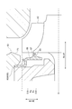
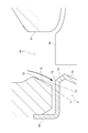
- FIG. 2 is an enlarged view of the vicinity of the back surface 49 and the back surface member 60 of the turbine impeller 42 in FIG. 1.
- FIG. 3 is a view showing a modification of the shape of the back side member 60 according to the modification.
- an annular back side member 60 60A, 60B
- the rear side member 60 60A, 60B
- FIGS. 2 and 3 show that in the turbine casing 40, an annular back side member 60 (60A, 60B) is provided to face the back surface 49 of the turbine impeller 42.
- the rear side member 60 (60A, 60B) is sandwiched between the turbine casing 40 and the bearing casing 20.
- the back side member 60 is configured by a heat shield plate provided to face the back surface 49 of the turbine impeller 42.
- the heat shield plate for suppressing heat transfer from the turbine casing 40 to the bearing casing 20 is used as the back side member 60, and the impeller facing surface 64 having the features described later is the heat shield plate (60) by forming by a thrust force F T acting on the back surface 49 of the turbine impeller 42 can be increased with a simple configuration.
- the back side member 60 protrudes toward the back surface 49 on the impeller facing surface 64 facing the back surface 49 of the turbine impeller 42. It has the convex part 65 extended to the circumferential direction.
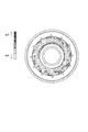
- the convex portion 65 extends in an arc shape along the circumferential direction when viewed from the axial direction of the turbine 41.
- the convex part 65 may be provided only with respect to the circumferential direction range of a part of the back surface side member 60, and may be provided continuously over the entire circumference of the back surface side member 60.
- the exhaust gas flow taken in from the scroll outlet portion 48 into the gap between the back surface 49 of the turbine impeller 42 and the impeller facing surface 64 is contracted by the convex portion 65.
- the static pressure applied to the back surface 49 of the turbine impeller 42 rises near the convex portion 65 or on the upstream side of the convex portion 65 (CFD analysis result of FIG. 5A and FIG.
- the static pressure is rising in the vicinity and on the upstream side of the convex portion 65), and the flow trying to bypass the convex portion 65 is on the back surface 49 of the turbine impeller. collide.
- FIG. 4A is a view showing the shape of a convex portion of a turbine according to a comparative example
- FIGS. 4B to 4D are results of CFD analysis of the turbine shown in FIG. 4A.
- the back side member 600 which opposes a turbine impeller contains several convex part 650 provided in the circumferential direction. Each protrusion 650 is provided along the radial direction so as to protrude toward the turbine impeller.
- the convex portion 650 having such a shape it is possible to reduce the swirling component of the exhaust gas flow which has flowed in between the impeller facing surface 664 of the rear side member 600 and the turbine impeller rear surface.
- the flow is greatly disturbed by the convex portion 650 between the impeller facing surface 664 of the back side member 600 and the turbine impeller back surface.
- the total pressure (see FIG. 4C) and the static pressure (see FIG. 4D) on the impeller rear side can be rather reduced by the convex portion 650.
- the convex portion 65 has a shape extending in the circumferential direction, the turbulence of the exhaust gas flow between the back surface 49 of the turbine impeller 42 and the impeller facing surface 64 The thrust force F T can be effectively increased while suppressing
- the impeller facing surface 64 of the back side member 60 is located radially outward of the convex portion 65 and extends in the radial direction, A second region 62 extending along the axial direction from the first region 61 toward the back surface 49 and forming a part of the outer surface of the convex portion 65, and radially inward of the second region 62, and convex And a third region 63 that forms another part of the outer surface of the portion 65.
- the second region 62 extends along the axial direction, the flow path of the exhaust gas can be narrowed sharply in the second region 62.
- the static pressure applied to the back surface 49 of the turbine impeller 42 can be further increased, and the exhaust gas flow colliding with the back surface 49 can be effectively formed. Therefore, it is possible to increase the thrust force F T acting on the back surface 49 of the turbine impeller 42 efficiently.
- the distance D between the back surface 49 of the turbine impeller 42 and the projection 65 is minimized at the radial position R 1 of the tip 67 of the projection 65. It is formed. According to such a configuration, exhaust gas flow taken in from the scroll outlet section 48 to the back 49, most flow path width is reduced at a radial position R 1 of the tip 67 of the protrusion 65. Thus, in the radial position R 1 or near the upstream side of the distal end 67 of the protruding portion 65 by the static pressure on the back 49 of the turbine impeller 42 is increased, the thrust force F T acting on the back surface 49 of the turbine impeller 42 It can be increased.
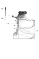
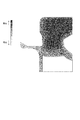
- FIG. 5A is a diagram showing the results of CFD analysis on the turbine 41 shown in FIG.
- FIG. 5B is a diagram showing the results of CFD analysis on a turbine according to a comparative example.
- the turbine 41 flow path width is minimum at the distal end 67 of the projecting portion 65, in the radial position R 1 or near the upstream side of the distal end 67 of the protrusion 65
- the static pressure applied to the back surface 49 of the turbine impeller 42 is higher than that of the comparative example. Therefore, if the turbine 41, a thrust force F T acting on the back surface 49 of the turbine impeller 42 can be said to relatively high.
- the radial position R 2 of the outermost peripheral portion 69 of the convex portion 65 is 0.6 r or more and 0. 6 when the radius of the turbine impeller 42 is r. It is included in the radial position range of 8r or less.
- the outermost peripheral portion 69 of the convex portion 65 at a radial position of 0.8 r or less, the static pressure increased in the vicinity of the convex portion 65 or on the upstream side of the convex portion 65 by the contraction flow effect ensuring a sufficient area of the back surface 49 to receive, it is possible to increase the thrust force F T acting on the back surface 49 of the turbine impeller 42 efficiently.
- the radial positions (R 1 , R 2 ) of the tip end 67 and the outermost peripheral portion 69 of the convex portion 65 coincide with each other. It is not limited. As in the embodiment illustrated in FIG. 3, the tip end 67 of the convex portion 65 may be located radially inward of the outermost peripheral portion 69 of the convex portion 65.
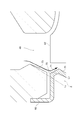
- FIG. 6 is an enlarged view for explaining the shape of the back side member 60 and the positional relationship between the scroll outlet portion 48 and the back side member 60 in the turbine according to some embodiments.
- the back side member 60 is located radially outward of the projection 65 and radially toward the inside of the turbine impeller 42 radially inward. It has a first tapered surface 71 formed diagonally.
- the flow path of the exhaust gas flowing between the back surface 49 of the turbine impeller and the back surface side member 60 can be narrowed to the back surface 49 side by the first tapered surface 71.
- the first tapered surface 71 is a flat surface angle theta 1 is less than or equal to 45 degrees 5 degrees of respect to the radial direction. According to such an embodiment, it is possible to squeeze the flow path of the exhaust gas at a desired angle to obtain the effect of increasing the thrust force F T and guide it to the back surface 49 side.
- the back side member 60 is located radially inward of the first tapered surface 71 and radially outward of the convex portion 65 so as to be separated radially inward from the back surface 49 of the turbine impeller 42. It has a second tapered surface 72 formed obliquely to the radial direction.
- the flow path narrowed by the first tapered surface 71 can be expanded by the second tapered surface 72.
- the expanded flow path can decelerate the exhaust gas flow and increase the static pressure acting on the back surface 49 of the turbine impeller 42.
- the static pressure is increased, it is possible to increase the thrust force F T acting on the back surface 49 of the turbine impeller 42.
- the first tapered surface 71 and the second tapered surface 72 may not be formed continuously.
- another surface formed to keep the channel width constant may be included between the first tapered surface 71 and the second tapered surface 72.
- the first tapered surface 71 may not be formed from the outermost periphery of the back side member 60.
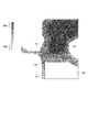
- FIG. 7A is a diagram showing the results of CFD analysis for the turbine according to the embodiment shown in FIG.
- FIG. 7B is a result of CFD analysis on the turbine according to the embodiment shown in FIG. 2 performed under the same analysis conditions as those shown in FIG. 7A.
- the static pressure on the upstream side of the convex portion 65 is greater than in the other case. It's getting higher.
- the hub sidewall surface 53 at the scroll outlet 48 is radially inwardly directed at the shroud sidewall surface 51, at least in part in the radial region.
- a third tapered surface 73 formed obliquely with respect to the radial direction so as to be separated in the axial direction.
- the swirl component of the exhaust gas from the scroll outlet portion 48 can be weakened by the third tapered surface 73 to smoothly guide the exhaust gas between the back surface 49 of the turbine impeller 42 and the back surface member 60 .
- the flow rate of the exhaust gas flowing between the back surface 49 and the back surface member 60 can be increased, and the pressure on the back surface 49 can be increased.
- FIG. 8A is a view showing the result of CFD analysis when the hub side wall surface 53 of the scroll outlet portion 48 includes the third tapered surface 73.
- FIG. 8B is a diagram showing the results of CFD analysis of the comparative example.
- the provision of the third tapered surface 73 weakens the swirling flow of the exhaust gas from the scroll outlet portion 48, and between the back surface 49 and the back surface member 60 of the turbine impeller 42. As a result, the exhaust gas from the scroll outlet portion 48 is smoothly introduced, and the pressure on the impeller rear side becomes high.
- the third tapered surface 73 forms an angle of 10 degrees or more and 40 degrees or less with respect to the radial direction. According to the study results of the present inventors, by a 40 degrees or less than 10 degrees the angle relative to the radial direction of the third tapered surface 73, the effect of a thrust force F T acting on the back surface 49 of the turbine impeller 42 Can be increased. This embodiment is obtained by using the above study results of the present inventors, it is possible to increase the thrust force F T that 49 acting on the back of the turbine impeller 42 efficiently. Furthermore, in one embodiment, the third tapered surface 73 is desirably an angle theta 2 which forms with respect to the radial direction is in the range of 26 degrees from 24 degrees, a large thrust force more by such an angle range F T can be obtained.
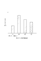
- Figure 9 is a graph showing the relationship between the inclination angle and the thrust force F T in the third tapered surface 73 with respect to the radial direction.
- the thrust force FT is larger in the case where the third tapered surface 73 is provided than in the case where the third tapered surface 73 is not provided.
- the thrust force F T is maximum at the inclination angle of the third tapered surface 73 of 24 degrees. is there.
- the outermost peripheral portion 75 of the first tapered surface 71 has a tangential line of the hub side wall surface 53 passing through the radially inner end of the third tapered surface 73 in a direction axially away from the shroud side wall surface 51.
- a first straight line L 1 is tilted degrees, is included in the region sandwiched between Z in the second linearly L 2 tilted 10 degrees in the direction toward the tangent of the third taper surface 73 in the axial direction to the shroud side wall surface 51.
- FIG. 10A is a view showing the flow of exhaust gas when the outermost peripheral portion 75 of the first tapered surface 71 is included in the region Z.
- FIG. 10B is a view showing the exhaust gas flow in the case where the outermost peripheral portion 75 of the first tapered surface 71 exists radially outward of the region Z with respect to the outermost peripheral portion 75 of the first tapered surface 71.
- FIG. 10C is a view showing the flow of exhaust gas in the case where the outermost peripheral portion 75 of the first tapered surface 71 exists radially inward of the region Z with respect to the outermost peripheral portion 75 of the first tapered surface 71.
- the outermost peripheral portion outermost peripheral portion 75 may on the other side of the region Z (radially inner) across the L 2, which jumped in the flow path of the exhaust gas of the first tapered surface 71
- the 75 prevents the exhaust gas flow and can cause pressure losses.
- the exhaust gas flow from the scroll outlet portion 48 can be smoothly guided to the back surface 49 of the turbine impeller 42.
- the pressure increase effect on the back surface 49 can be effectively enjoyed.
- the line L 3 which extended the tangent of the hub-side wall surface 53 through the radially inner end of the third taper surface 73 is preferably intersects the outermost peripheral portion 75 of the first tapered surface 71. According to such an embodiment, in the exhaust gas flow path from the scroll outlet portion 48 to the back surface 49 side of the turbine impeller 42, the formation of the inhibition structure and the dead area in the exhaust gas flow path can be effectively suppressed. The pressure increase effect can be enhanced.
- a representation representing a relative or absolute arrangement such as “in a direction”, “along a direction”, “parallel”, “orthogonal”, “center”, “concentric” or “coaxial”
- a representation representing a relative or absolute arrangement such as “in a direction”, “along a direction”, “parallel”, “orthogonal”, “center”, “concentric” or “coaxial”
- expressions that indicate that things such as “identical”, “equal” and “homogeneous” are equal states not only represent strictly equal states, but also have tolerances or differences with which the same function can be obtained. It also represents the existing state.
- expressions representing shapes such as a square shape and a cylindrical shape not only indicate shapes such as a square shape and a cylindrical shape in a geometrically strict sense, but also within the range where the same effect can be obtained. Also, the shape including the uneven portion, the chamfered portion, and the like shall be indicated. Moreover, in the present specification, the expressions “comprising”, “including” or “having” one component are not exclusive expressions excluding the presence of other components.
- turbocharger 20 bearing casing 22 rotating shaft 24 radial bearing 26 thrust bearing 30 compressor casing 31 compressor 32 compressor impeller 34 air inlet portion 36 diffuser flow path 37 scroll flow path (compressor) 39 back (compressor) 40 turbine casing 41 turbine 42 turbine impeller 46 scroll passage (turbine) 48 scroll outlet 49 back (turbine) Reference Signs List 51 shroud side wall surface 53 hub side wall surface 55 gas discharge portion 60 back side member 61 first region 62 second region 63 third region 64 impeller facing surface 65 convex portion 67 distal end 69 outermost peripheral portion (convex portion) 71 first tapered surface 72 second tapered surface 73 third tapered surface 75 outermost peripheral portion (first tapered surface)
Landscapes
- Engineering & Computer Science (AREA)
- Mechanical Engineering (AREA)
- General Engineering & Computer Science (AREA)
- Chemical & Material Sciences (AREA)
- Combustion & Propulsion (AREA)
- Supercharger (AREA)
Abstract
L'invention concerne une turbine pour turbocompresseur comprenant : une hélice de turbine raccordée à une hélice de compresseur par l'intermédiaire d'un arbre rotatif ; un carter de turbine disposé de manière à couvrir l'hélice de turbine et comprenant un passage d'écoulement en spirale et une sortie de spirale qui est disposée radialement à l'intérieur du passage d'écoulement en spirale et qui conduit, vers l'hélice de turbine, un gaz d'échappement s'écoulant depuis le passage d'écoulement en spirale ; et un élément côté surface arrière disposé de façon à être tourné vers la surface arrière de l'hélice de turbine. L'élément côté surface arrière comporte, sur sa surface tournée vers l'hélice qui fait face à la surface arrière de la roue, une saillie faisant saillie vers la surface arrière et s'étendant dans une direction circonférentielle.
Priority Applications (5)
| Application Number | Priority Date | Filing Date | Title |
|---|---|---|---|
| CN201780089489.6A CN110546357B (zh) | 2017-08-10 | 2017-08-10 | 涡轮增压器用涡轮机以及涡轮增压器 |
| JP2019535536A JP6759463B2 (ja) | 2017-08-10 | 2017-08-10 | ターボチャージャ用タービン及びターボチャージャ |
| EP17921069.5A EP3617476B1 (fr) | 2017-08-10 | 2017-08-10 | Turbine pour turbocompresseur et turbocompresseur |
| US16/615,588 US11174870B2 (en) | 2017-08-10 | 2017-08-10 | Turbine for turbocharger, and turbocharger |
| PCT/JP2017/029080 WO2019030892A1 (fr) | 2017-08-10 | 2017-08-10 | Turbine pour turbocompresseur et turbocompresseur |
Applications Claiming Priority (1)
| Application Number | Priority Date | Filing Date | Title |
|---|---|---|---|
| PCT/JP2017/029080 WO2019030892A1 (fr) | 2017-08-10 | 2017-08-10 | Turbine pour turbocompresseur et turbocompresseur |
Publications (1)
| Publication Number | Publication Date |
|---|---|
| WO2019030892A1 true WO2019030892A1 (fr) | 2019-02-14 |
Family
ID=65271932
Family Applications (1)
| Application Number | Title | Priority Date | Filing Date |
|---|---|---|---|
| PCT/JP2017/029080 Ceased WO2019030892A1 (fr) | 2017-08-10 | 2017-08-10 | Turbine pour turbocompresseur et turbocompresseur |
Country Status (5)
| Country | Link |
|---|---|
| US (1) | US11174870B2 (fr) |
| EP (1) | EP3617476B1 (fr) |
| JP (1) | JP6759463B2 (fr) |
| CN (1) | CN110546357B (fr) |
| WO (1) | WO2019030892A1 (fr) |
Citations (5)
| Publication number | Priority date | Publication date | Assignee | Title |
|---|---|---|---|---|
| JPS6194242U (fr) * | 1984-11-27 | 1986-06-18 | ||
| WO2011067259A1 (fr) * | 2009-12-02 | 2011-06-09 | Continental Automotive Gmbh | Turbocompresseur |
| JP2013015120A (ja) * | 2011-07-06 | 2013-01-24 | Ihi Corp | ターボチャージャ |
| JP2014234713A (ja) | 2013-05-31 | 2014-12-15 | 株式会社Ihi | ラジアルタービン及び過給機 |
| JP2016020652A (ja) * | 2014-07-14 | 2016-02-04 | 株式会社Ihi | 過給機及び遮熱板の製造方法 |
Family Cites Families (25)
| Publication number | Priority date | Publication date | Assignee | Title |
|---|---|---|---|---|
| US3411706A (en) * | 1966-08-24 | 1968-11-19 | Wallace Murray Corp | Bearing durability enhancement device for turbocharger |
| US4101241A (en) * | 1976-05-19 | 1978-07-18 | Kabushiki Kaisha Komatsu Seisakusho | Super charger with fluid biased heat shroud |
| DE2735034C2 (de) * | 1976-08-19 | 1981-09-24 | Kabushiki Kaisha Komatsu Seisakusho, Tokyo | Abgasturbolader |
| DE2829150A1 (de) * | 1978-07-03 | 1980-01-24 | Barmag Barmer Maschf | Abgasturbolader |
| CH638867A5 (de) * | 1979-03-16 | 1983-10-14 | Bbc Brown Boveri & Cie | Turbolader mit einer einrichtung zur regelung des schluckvermoegens der turbine. |
| JPS56141022A (en) * | 1980-04-07 | 1981-11-04 | Toyota Motor Corp | Fixing mechanism for hermetically fitting of composing member in turbocharger |
| JPS56148620A (en) * | 1980-04-17 | 1981-11-18 | Toyota Motor Corp | Turbo charger |
| US4460284A (en) * | 1981-12-31 | 1984-07-17 | Cummins Engine Company, Inc. | Turbocharger assembly including a flexible anti-friction bearing support |
| US4786238A (en) * | 1984-12-20 | 1988-11-22 | Allied-Signal Inc. | Thermal isolation system for turbochargers and like machines |
| US4725206A (en) * | 1984-12-20 | 1988-02-16 | The Garrett Corporation | Thermal isolation system for turbochargers and like machines |
| JPS62214232A (ja) | 1986-03-17 | 1987-09-21 | Hitachi Ltd | 内燃機関の排気ガスによつて駆動されるタ−ビン |
| JPS62282126A (ja) * | 1986-05-30 | 1987-12-08 | Honda Motor Co Ltd | タ−ビンの可変ノズル構造 |
| US4880351A (en) * | 1986-05-30 | 1989-11-14 | Honda Giken Kogyo Kabushiki Kaisha | Variable capacity turbine |
| US5028208A (en) * | 1989-01-10 | 1991-07-02 | Ishikawajima-Harima Jukogyo Kabushiki Kaisha | Nozzle blade angle adjustment device for variable geometry turbocharger |
| JP4468286B2 (ja) * | 2005-10-21 | 2010-05-26 | 三菱重工業株式会社 | 排気ターボ式過給機 |
| JP4826417B2 (ja) * | 2006-09-29 | 2011-11-30 | 株式会社ジェイテクト | 過給器 |
| JP2010270732A (ja) * | 2009-05-25 | 2010-12-02 | Ihi Corp | インペラ及び過給機 |
| JP2013174129A (ja) * | 2012-02-23 | 2013-09-05 | Mitsubishi Heavy Ind Ltd | ターボチャージャ |
| EP2940270B1 (fr) * | 2012-12-27 | 2017-04-26 | Mitsubishi Heavy Industries, Ltd. | Turbocompresseur à géométrie variable |
| JP2014234803A (ja) * | 2013-06-05 | 2014-12-15 | 株式会社Ihi | 可変容量型タービン及び可変容量型過給機 |
| US9840926B2 (en) * | 2013-07-10 | 2017-12-12 | United Technologies Corporation | Abrasive flow media fixture with end contour |
| CN108757063B (zh) * | 2013-12-27 | 2021-04-02 | 三菱重工发动机和增压器株式会社 | 涡轮壳体 |
| US10669889B2 (en) * | 2014-02-04 | 2020-06-02 | Borgwarner Inc. | Heat shield for mixed flow turbine wheel turbochargers |
| US10690141B2 (en) * | 2014-02-25 | 2020-06-23 | Mitsubishi Heavy Industries Engine & Turbocharger, Ltd. | Seal structure and supercharger provided with the seal structure |
| WO2016071959A1 (fr) * | 2014-11-04 | 2016-05-12 | 三菱重工業株式会社 | Logement de turbine et procédé de fabrication de logement de turbine |
-
2017
- 2017-08-10 WO PCT/JP2017/029080 patent/WO2019030892A1/fr not_active Ceased
- 2017-08-10 JP JP2019535536A patent/JP6759463B2/ja active Active
- 2017-08-10 CN CN201780089489.6A patent/CN110546357B/zh active Active
- 2017-08-10 EP EP17921069.5A patent/EP3617476B1/fr active Active
- 2017-08-10 US US16/615,588 patent/US11174870B2/en active Active
Patent Citations (5)
| Publication number | Priority date | Publication date | Assignee | Title |
|---|---|---|---|---|
| JPS6194242U (fr) * | 1984-11-27 | 1986-06-18 | ||
| WO2011067259A1 (fr) * | 2009-12-02 | 2011-06-09 | Continental Automotive Gmbh | Turbocompresseur |
| JP2013015120A (ja) * | 2011-07-06 | 2013-01-24 | Ihi Corp | ターボチャージャ |
| JP2014234713A (ja) | 2013-05-31 | 2014-12-15 | 株式会社Ihi | ラジアルタービン及び過給機 |
| JP2016020652A (ja) * | 2014-07-14 | 2016-02-04 | 株式会社Ihi | 過給機及び遮熱板の製造方法 |
Non-Patent Citations (1)
| Title |
|---|
| See also references of EP3617476A4 |
Also Published As
| Publication number | Publication date |
|---|---|
| EP3617476B1 (fr) | 2022-04-13 |
| CN110546357B (zh) | 2021-10-08 |
| CN110546357A (zh) | 2019-12-06 |
| EP3617476A4 (fr) | 2020-05-06 |
| JP6759463B2 (ja) | 2020-09-23 |
| EP3617476A1 (fr) | 2020-03-04 |
| US20200088212A1 (en) | 2020-03-19 |
| JPWO2019030892A1 (ja) | 2020-04-23 |
| US11174870B2 (en) | 2021-11-16 |
Similar Documents
| Publication | Publication Date | Title |
|---|---|---|
| JP5221985B2 (ja) | 遠心圧縮機 | |
| JP5649758B2 (ja) | 遠心圧縮機 | |
| JP5599528B2 (ja) | 遠心圧縮機 | |
| JP7082948B2 (ja) | 遠心圧縮機、ターボチャージャ | |
| JPWO2016031017A1 (ja) | 膨張タービン及びターボチャージャ | |
| CN111911455A (zh) | 离心压缩机的叶轮、离心压缩机以及涡轮增压器 | |
| CN101372899A (zh) | 具有滑动活塞组件的涡轮增压器 | |
| JP7123029B2 (ja) | 遠心圧縮機 | |
| WO2023248534A1 (fr) | Roue de compresseur centrifuge, compresseur centrifuge et turbocompresseur | |
| WO2021234886A1 (fr) | Boîtier de compresseur et compresseur centrifuge | |
| WO2019123566A1 (fr) | Turbine et turbocompresseur | |
| JP7336026B2 (ja) | タービン及びこのタービンを備えるターボチャージャ | |
| WO2019030892A1 (fr) | Turbine pour turbocompresseur et turbocompresseur | |
| WO2022029932A1 (fr) | Turbine pour compresseur centrifuge, et compresseur centrifuge | |
| JP7445005B2 (ja) | コンプレッサハウジングおよび遠心圧縮機 | |
| JP2014234713A (ja) | ラジアルタービン及び過給機 | |
| JP7413514B2 (ja) | スクロールケーシングおよび遠心圧縮機 | |
| JP7749509B2 (ja) | タービンハウジングおよび可変容量型のターボチャージャ | |
| JP7303763B2 (ja) | 排気ディフューザ及びタービンハウジング、並びに過給機 | |
| JP7445004B2 (ja) | コンプレッサハウジングおよび遠心圧縮機 | |
| JP7463498B2 (ja) | 流れが最適化された軸方向ディフューザ内へのウェイストゲート質量流の同心的な導入 | |
| WO2025115456A1 (fr) | Corps de compresseur centrifuge, compresseur centrifuge et turbocompresseur |
Legal Events
| Date | Code | Title | Description |
|---|---|---|---|
| 121 | Ep: the epo has been informed by wipo that ep was designated in this application |
Ref document number: 17921069 Country of ref document: EP Kind code of ref document: A1 |
|
| ENP | Entry into the national phase |
Ref document number: 2017921069 Country of ref document: EP Effective date: 20191125 |
|
| ENP | Entry into the national phase |
Ref document number: 2019535536 Country of ref document: JP Kind code of ref document: A |
|
| NENP | Non-entry into the national phase |
Ref country code: DE |