WO2019031027A1 - クラッド材およびクラッド材の製造方法 - Google Patents
クラッド材およびクラッド材の製造方法 Download PDFInfo
- Publication number
- WO2019031027A1 WO2019031027A1 PCT/JP2018/020405 JP2018020405W WO2019031027A1 WO 2019031027 A1 WO2019031027 A1 WO 2019031027A1 JP 2018020405 W JP2018020405 W JP 2018020405W WO 2019031027 A1 WO2019031027 A1 WO 2019031027A1
- Authority
- WO
- WIPO (PCT)
- Prior art keywords
- layer
- thickness
- sus
- rolling
- clad
- Prior art date
- Legal status (The legal status is an assumption and is not a legal conclusion. Google has not performed a legal analysis and makes no representation as to the accuracy of the status listed.)
- Ceased
Links
Images





Classifications
-
- B—PERFORMING OPERATIONS; TRANSPORTING
- B32—LAYERED PRODUCTS
- B32B—LAYERED PRODUCTS, i.e. PRODUCTS BUILT-UP OF STRATA OF FLAT OR NON-FLAT, e.g. CELLULAR OR HONEYCOMB, FORM
- B32B15/00—Layered products comprising a layer of metal
- B32B15/01—Layered products comprising a layer of metal all layers being exclusively metallic
- B32B15/013—Layered products comprising a layer of metal all layers being exclusively metallic one layer being formed of an iron alloy or steel, another layer being formed of a metal other than iron or aluminium
- B32B15/015—Layered products comprising a layer of metal all layers being exclusively metallic one layer being formed of an iron alloy or steel, another layer being formed of a metal other than iron or aluminium the said other metal being copper or nickel or an alloy thereof
-
- B—PERFORMING OPERATIONS; TRANSPORTING
- B21—MECHANICAL METAL-WORKING WITHOUT ESSENTIALLY REMOVING MATERIAL; PUNCHING METAL
- B21B—ROLLING OF METAL
- B21B1/00—Metal-rolling methods or mills for making semi-finished products of solid or profiled cross-section; Sequence of operations in milling trains; Layout of rolling-mill plant, e.g. grouping of stands; Succession of passes or of sectional pass alternations
- B21B1/22—Metal-rolling methods or mills for making semi-finished products of solid or profiled cross-section; Sequence of operations in milling trains; Layout of rolling-mill plant, e.g. grouping of stands; Succession of passes or of sectional pass alternations for rolling plates, strips, bands or sheets of indefinite length
-
- B—PERFORMING OPERATIONS; TRANSPORTING
- B23—MACHINE TOOLS; METAL-WORKING NOT OTHERWISE PROVIDED FOR
- B23K—SOLDERING OR UNSOLDERING; WELDING; CLADDING OR PLATING BY SOLDERING OR WELDING; CUTTING BY APPLYING HEAT LOCALLY, e.g. FLAME CUTTING; WORKING BY LASER BEAM
- B23K20/00—Non-electric welding by applying impact or other pressure, with or without the application of heat, e.g. cladding or plating
- B23K20/04—Non-electric welding by applying impact or other pressure, with or without the application of heat, e.g. cladding or plating by means of a rolling mill
-
- B—PERFORMING OPERATIONS; TRANSPORTING
- B32—LAYERED PRODUCTS
- B32B—LAYERED PRODUCTS, i.e. PRODUCTS BUILT-UP OF STRATA OF FLAT OR NON-FLAT, e.g. CELLULAR OR HONEYCOMB, FORM
- B32B15/00—Layered products comprising a layer of metal
- B32B15/01—Layered products comprising a layer of metal all layers being exclusively metallic
-
- C—CHEMISTRY; METALLURGY
- C21—METALLURGY OF IRON
- C21D—MODIFYING THE PHYSICAL STRUCTURE OF FERROUS METALS; GENERAL DEVICES FOR HEAT TREATMENT OF FERROUS OR NON-FERROUS METALS OR ALLOYS; MAKING METAL MALLEABLE, e.g. BY DECARBURISATION OR TEMPERING
- C21D1/00—General methods or devices for heat treatment, e.g. annealing, hardening, quenching or tempering
- C21D1/26—Methods of annealing
-
- C—CHEMISTRY; METALLURGY
- C22—METALLURGY; FERROUS OR NON-FERROUS ALLOYS; TREATMENT OF ALLOYS OR NON-FERROUS METALS
- C22C—ALLOYS
- C22C38/00—Ferrous alloys, e.g. steel alloys
- C22C38/18—Ferrous alloys, e.g. steel alloys containing chromium
- C22C38/40—Ferrous alloys, e.g. steel alloys containing chromium with nickel
-
- C—CHEMISTRY; METALLURGY
- C22—METALLURGY; FERROUS OR NON-FERROUS ALLOYS; TREATMENT OF ALLOYS OR NON-FERROUS METALS
- C22C—ALLOYS
- C22C9/00—Alloys based on copper
-
- B—PERFORMING OPERATIONS; TRANSPORTING
- B23—MACHINE TOOLS; METAL-WORKING NOT OTHERWISE PROVIDED FOR
- B23K—SOLDERING OR UNSOLDERING; WELDING; CLADDING OR PLATING BY SOLDERING OR WELDING; CUTTING BY APPLYING HEAT LOCALLY, e.g. FLAME CUTTING; WORKING BY LASER BEAM
- B23K2103/00—Materials to be soldered, welded or cut
- B23K2103/02—Iron or ferrous alloys
- B23K2103/04—Steel or steel alloys
- B23K2103/05—Stainless steel
-
- B—PERFORMING OPERATIONS; TRANSPORTING
- B23—MACHINE TOOLS; METAL-WORKING NOT OTHERWISE PROVIDED FOR
- B23K—SOLDERING OR UNSOLDERING; WELDING; CLADDING OR PLATING BY SOLDERING OR WELDING; CUTTING BY APPLYING HEAT LOCALLY, e.g. FLAME CUTTING; WORKING BY LASER BEAM
- B23K2103/00—Materials to be soldered, welded or cut
- B23K2103/08—Non-ferrous metals or alloys
- B23K2103/12—Copper or alloys thereof
-
- B—PERFORMING OPERATIONS; TRANSPORTING
- B23—MACHINE TOOLS; METAL-WORKING NOT OTHERWISE PROVIDED FOR
- B23K—SOLDERING OR UNSOLDERING; WELDING; CLADDING OR PLATING BY SOLDERING OR WELDING; CUTTING BY APPLYING HEAT LOCALLY, e.g. FLAME CUTTING; WORKING BY LASER BEAM
- B23K2103/00—Materials to be soldered, welded or cut
- B23K2103/18—Dissimilar materials
- B23K2103/22—Ferrous alloys and copper or alloys thereof
-
- C—CHEMISTRY; METALLURGY
- C21—METALLURGY OF IRON
- C21D—MODIFYING THE PHYSICAL STRUCTURE OF FERROUS METALS; GENERAL DEVICES FOR HEAT TREATMENT OF FERROUS OR NON-FERROUS METALS OR ALLOYS; MAKING METAL MALLEABLE, e.g. BY DECARBURISATION OR TEMPERING
- C21D2211/00—Microstructure comprising significant phases
- C21D2211/001—Austenite
-
- C—CHEMISTRY; METALLURGY
- C21—METALLURGY OF IRON
- C21D—MODIFYING THE PHYSICAL STRUCTURE OF FERROUS METALS; GENERAL DEVICES FOR HEAT TREATMENT OF FERROUS OR NON-FERROUS METALS OR ALLOYS; MAKING METAL MALLEABLE, e.g. BY DECARBURISATION OR TEMPERING
- C21D2251/00—Treating composite or clad material
- C21D2251/02—Clad material
-
- H—ELECTRICITY
- H05—ELECTRIC TECHNIQUES NOT OTHERWISE PROVIDED FOR
- H05K—PRINTED CIRCUITS; CASINGS OR CONSTRUCTIONAL DETAILS OF ELECTRIC APPARATUS; MANUFACTURE OF ASSEMBLAGES OF ELECTRICAL COMPONENTS
- H05K5/00—Casings, cabinets or drawers for electric apparatus
- H05K5/04—Metal casings
Definitions
- the present invention relates to a clad material and a method of manufacturing the clad material.
- a clad material is formed by rolling and joining first and third layers made of stainless steel and a second layer made of Cu or a Cu alloy disposed between the first and third layers.
- first and third layers made of stainless steel
- second layer made of Cu or a Cu alloy disposed between the first and third layers.
- a cover layer (first layer, third layer) made of stainless steel is rolled and bonded on both sides of a central layer (second layer) made of copper or copper alloy.
- the cover layer is bonded to the central layer through a barrier layer made of Nb or the like.
- the clad plate is rolled and joined by thickness reduction processing such as hot rolling and warm cold rolling.
- the clad material disclosed in Japanese Patent Application Laid-Open No. 2005-219478 has a place where the thickness is excessively small in the first layer or the third layer formed of stainless steel. It has been discovered that in some cases, as a result, welding strength may be reduced when welding the clad material to another member, and that mechanical strength variation of the clad material may occur.
- the present invention has been made to solve the problems as described above, and one object of the present invention is to reduce the welding strength when welding a clad material to another member, and a clad material It is an object of the present invention to provide a clad material and a method of manufacturing the clad material, which can suppress the occurrence of the mechanical strength variation.
- the inventor of the present application has found that the minimum thickness in the stacking direction of the first layer and the minimum thickness in the stacking direction of the third layer are excessive with respect to the target thickness (target value). It has further been found that, due to the small size, the welding strength may be reduced when welding the clad material to other members, and that the mechanical strength of the clad material may vary. The present invention has been completed based on such findings.
- the clad material according to the first aspect of the present invention comprises the first layer made of stainless steel, the second layer made of Cu or Cu alloy, and the second layer rolled and joined to the first layer, and stainless steel And the third layer rolled and joined to the side opposite to the first layer of the second layer, and the total thickness is 1 mm or less, and in a cross-sectional view along the stacking direction, the first layer in the stacking direction
- the minimum thickness and the minimum thickness in the stacking direction of the third layer are 70% or more and less than 100% of the average thickness in the stacking direction of the first layer and the average thickness in the stacking direction of the third layer, respectively.
- Stainless steel means an alloy containing 50 mass% or more of Fe (iron) as a main component and further containing at least 10.5 mass% of Cr (chromium).
- Cu alloy means an alloy containing Cu (copper) as a main component at 50% by mass or more.
- the “minimum thickness of the first layer in the stacking direction” and the “minimum thickness of the third layer in the stacking direction” have predetermined lengths along the rolling direction of the clad material in the cross-sectional view along the stacking direction. This means the minimum of the thickness of the first layer and the minimum of the thickness of the third layer in the thickness range.
- the minimum thickness in the stacking direction of the first layer and the minimum thickness in the stacking direction of the third layer are each It is 70% or more and less than 100% of the average thickness in the stacking direction of one layer and the average thickness in the stacking direction of the third layer.
- the thickness in the stacking direction of the first layer and the third layer is equalized, so that the location where the thickness is excessively small in the first layer and the third layer (less than 70% of the average thickness) Can be suppressed.
- the effect of this configuration is particularly effective when the overall thickness is as small as 1 mm or less and the average thickness of the first and third layers is small (for example, 0.20 mm or less).
- the first layer and the third layer may be broken or pinholes, and the second layer is not coated. It can control that a place arises.
- the clad material according to the first aspect is, as described above, a first layer made of stainless steel, a second layer made of Cu or a Cu alloy, and rolled and joined to the first layer, stainless steel And a third layer rolled and joined to the side opposite to the first layer of the second layer.
- the second layer composed of Cu or a Cu alloy while maintaining mechanical strength and corrosion resistance with the first layer and third layer composed of stainless steel, and conductivity and heat Conductivity can be secured.
- the standard deviation of the percentage of the minimum thickness of the first layer with respect to the thickness of the clad material and the standard deviation of the percentage of the minimum thickness of the third layer with respect to the thickness of the clad material are It is 1.5% or less.
- the first layer and the third layer are both made of austenitic stainless steel.
- the austenitic stainless steel and Cu or Cu alloy are nonmagnetic, the entire clad material can be made nonmagnetic.
- a method of manufacturing a clad material comprising: a first metal plate made of stainless steel; a second metal plate made of Cu or a Cu alloy; and a third metal made of stainless steel
- a clad rolling including rolling and joining in a state in which the plate and the steel are stacked in this order, and the clad rolling with a pressure contact load of 4.4 ⁇ 10 3 N / mm or more makes the first member made of stainless steel Layer, a second layer formed of Cu or Cu alloy and roll bonded to the first layer, and a third layer formed of stainless steel and roll bonded to the opposite side of the first layer of the second layer
- the minimum thickness of the first layer in the stacking direction and the minimum thickness of the third layer in the stacking direction are each in the stacking direction of the first layer.
- the “pressure contact load” in the present invention is the combined force of forces acting on the rolling roller from the rolled material (in the present invention, the first metal plate, the second metal plate and the third metal plate) during clad rolling. And the force per unit length.
- This pressure contact load may also be referred to as rolling load or pressure reduction.
- the first metal plate made of stainless steel, the second metal plate made of Cu or Cu alloy, and stainless steel are used. Clad rolling is performed with a pressure contact load of 4.4 ⁇ 10 3 N / mm or more in a state in which the third metal plate thus stacked is laminated in this order. Thus, clad rolling is performed with a sufficient pressure contact load of 4.4 ⁇ 10 3 N / mm or more, and therefore, the first and third metal plates made of stainless steel and Cu or a Cu alloy are used. It is possible to suppress rolling such that each layer is plastically deformed nonuniformly due to the difference in ductility with the second metal sheet.
- the clad material it is possible to prevent the thickness in the stacking direction of the first layer and the thickness in the stacking direction of the third layer from becoming uneven, so the first layer or the third layer made of stainless steel It is possible to suppress the occurrence of an excessively small thickness in the three layers.
- the first layer and the third layer may be broken or pinholes, and the second layer is not coated. Can be suppressed.
- the pressing load is set to 4.9 ⁇ 10 3 N / mm or more.
- the clad rolling can be performed with a more sufficient pressure contact load, and therefore, it is possible to further suppress rolling so that each layer is plastically deformed nonuniformly.
- the second metal plate to be prepared is temper-rolled and work-hardened after being subjected to annealing treatment.
- a second metal plate made of Cu or a Cu alloy a second metal plate in which internal stress (strain) is accumulated and mechanical strength (0.2% proof stress or the like) is improved It can be used.
- the mechanical strength of the second metal plate which is lower in mechanical strength compared to the first metal plate and the third metal plate made of stainless steel, is used as the mechanical strength of the first metal plate and the third metal plate. It can be approached.
- each layer is rolled so as to plastically deform more uniformly. Therefore, the first metal plate, the second metal plate, and the third metal While being able to fully join with a board, the thickness of each layer can be formed with high precision.
- the second metal plate to be prepared has a thickness after temper rolling of at least 60% and less than 100% of the thickness before temper rolling.
- the internal stress (the second metal plate to be prepared) is obtained due to the thickness after temper rolling being less than 60% of the thickness before temper rolling. Excessive accumulation of distortion can be suppressed.
- the crystal of the second layer (the second metal plate) can be prevented from becoming coarse due to a large internal stress (strain), so the elongation of the cladding material (processing) can be attributed to the second layer. Can be suppressed.
- the present invention it is possible to suppress the decrease in welding strength when welding a clad material to another member, and the clad that can suppress the occurrence of variations in mechanical strength of the clad material. It is possible to provide a material and a method of manufacturing the clad material.
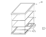
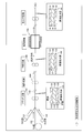
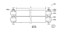
- FIG. 1 is a cross-sectional view showing a structure of a clad material (chassis) according to an embodiment of the present invention. It is a schematic diagram for demonstrating the manufacturing process of the clad material by one Embodiment of this invention. It is a schematic diagram for demonstrating the manufacturing process of the clad material by one Embodiment of this invention. It is the front view which showed the rolling roller for producing the clad material by one Embodiment of this invention.
- FIG. 5 is an enlarged side view showing a rolling roller for producing a clad material according to an embodiment of the present invention.
- the portable device 100 includes an upper housing 1a, a display 2, a chassis 3, a substrate 4, a battery 5, and a lower housing 1b.
- the display 2, the chassis 3, the substrate 4, and the battery 5 are disposed in the lower housing 1 b in this order from the upper side (Z 1 side).
- the lower housing 1b is covered by the upper housing 1a from above.
- the display 2 includes a liquid crystal display, an organic EL display, and the like, and has a function of displaying an image on the upper surface on the Z1 side.
- the chassis 3 has a function of securing the mechanical strength of the portable device 100 and a function of emitting heat from the display 2, the substrate 4 (electronic component 4 a) and the battery 5 to the outside. That is, the chassis 3 doubles as a heat sink. Further, a member (not shown) of the portable device 100 is welded to the chassis 3.
- the substrate 4 is disposed on the X1 side of the lower housing 1b, and the battery 5 is disposed on the X2 side.
- an electronic component 4a such as a CPU (Central Processing Unit) for driving an application is disposed.
- a SUS layer 31 made of stainless steel, a Cu layer 32 made of Cu or a Cu alloy, and a SUS layer 33 made of stainless steel are stacked in this order. It is comprised from the clad material 30 of 3 layer structure.
- the Cu layer 32 is rolled and joined to the Z1 side surface (upper surface) of the SUS layer 33 and is rolled and joined to the Z2 side surface (lower surface) of the SUS layer 31.
- the respective layers form an interatomic bond by diffusion annealing to strongly bond each other.
- SUS layer 31 and the SUS layer 33 are examples of the “first layer”, the “second layer”, and the “third layer” in the claims respectively.
- the thickness t1 of the cladding material 30 in the Z direction is not particularly limited.
- the thickness t1 of the chassis 3 is preferably 1 mm or less, and more preferably 0 in order to suppress an increase in the thickness in the Z direction in consideration of the weight reduction and the size reduction of the portable device 100. .5 mm or less.
- the thickness t1 of the chassis 3 is preferably 0.03 mm or more, more preferably 0.05 mm or more, and further preferably Is preferably 0.1 mm or more.
- the thickness of the Cu layer 32 be larger than that of the SUS layers (31, 33) from the viewpoint of heat dissipation.
- the thickness of the Cu layer 32 is too large, the thickness of the SUS layer (31, 33) becomes small, and when it is rolled and joined to the Cu layer 32, there is a possibility that a tear or a pinhole may occur. As a result, there is a possibility that a place where the Cu layer 32 is not covered with the SUS layer (31, 33) may occur. Therefore, when the thickness of the SUS layer is 1, the layer thickness ratio (SUS layer: Cu layer: SUS layer) is 2 to 8 (1: 2: 1 to 1: 8: 1). Preferably there.
- the stainless steel constituting the SUS layer 31 and the SUS layer 33 is not particularly limited as long as it is stainless steel, such as austenite, ferrite and martensite.
- the chassis 3 it is not preferable that the chassis 3 be magnetic in the portable device 100 including the electronic component 4a (see FIG. 1). Therefore, the stainless steel forming the SUS layer 31 and the SUS layer 33 is preferably an austenitic stainless steel, and more preferably a so-called SUS300-based (JIS standard) austenitic stainless steel.
- the stainless steel constituting the SUS layer 31 and the SUS layer 33 be SUS316L (JIS standard) which has a small content of C (carbon) and is less likely to be magnetic.
- SUS316 JIS standard
- SUS316 JIS standard
- the SUS layer 31 and the SUS layer 33 are not limited to the same composition, it is preferable to be made of stainless steel having the same composition in consideration of rolling stability and the like.
- the Cu layer 32 is made of Cu of C1000 series (JIS standard) or Cu alloy such as C2000 series (JIS standard). Examples of Cu include so-called oxygen free copper, phosphorus-deoxidized copper, tough pitch copper and the like. Further, as the Cu alloy, a Zr-Cu alloy of C1050 (JIS standard) or the like is preferable in order to suppress crystal coarsening. Generally, Cu or a Cu alloy constituting the Cu layer 32 has higher thermal conductivity and larger ductility than stainless steels constituting the SUS layer 31 and the SUS layer 33.
- the grain size of the Cu layer 32 (Cu or Cu alloy) measured by the comparative method of JIS H 0501 is preferably 0.150 mm or less, and the elongation (ductility) of the Cu layer 32 is prevented from being reduced. can do.
- the thicknesses t2 and t3 of the SUS layers 31 and 33 vary in the rolling direction, respectively.
- minimum thicknesses t2 min and t3 min smaller than the thicknesses t2 and t3 of the other portions exist, respectively.
- the interface of the cladding material 30 becomes wavy in a cross-sectional view along the stacking direction (Z direction).
- the wave form of the interface is shown exaggeratingly.
- the minimum thickness t2min in the stacking direction of the SUS layer 31 and the minimum thickness t3min in the stacking direction of the SUS layer 33 are respectively
- the average thickness t2avg in the stacking direction of the SUS layer 31 and the average thickness t3avg in the stacking direction of the SUS layer 33 are 70% or more and less than 100%.
- the minimum thickness t2min in the stacking direction of the SUS layer 31 is the minimum thickness t2 of the SUS layer 31 in a predetermined range (length) in the rolling direction of the clad material 30.
- the minimum thickness t3min in the stacking direction of the SUS layer 33 is the minimum thickness t3 of the SUS layer 33 in a predetermined range (length) in the rolling direction of the clad material 30.
- the above-mentioned predetermined range (length) in the clad material 30 is not particularly limited as long as it is a range of one or more wavelengths of the wave of the interface formed in a wave shape, but from the viewpoint of measurement reliability It is good.
- the average thickness t2avg of the SUS layer 31 in the stacking direction is the average of the thickness t2 of the SUS layer 31 in the clad material 30.
- the average thickness t3avg of the SUS layer 33 in the stacking direction is the average of the thickness t3 of the SUS layer 33 in the clad material 30.
- the average thicknesses t2avg and t3avg respectively measure the thicknesses t2 and t3 at a plurality of locations (e.g., 10 or more locations) of the SUS layers 31 and 33 at random, for example, in the predetermined range (length) of the cladding material 30 described above.
- the thickness t4 of the Cu layer 32 is the same as the average thicknesses t2avg and t3avg of the SUS layers 31 and 33 described above as the average thickness t4avg (hereinafter, simply referred to as "t4" because of little variation). It is good to ask by
- the standard deviation (%) of the percentage of the minimum thickness t2min of the SUS layer 31 to the thickness t1 of the clad material 30 and the standard deviation (%) of the percentage of the minimum thickness t3min of the SUS layer 33 to the thickness t1 of the clad material 30 are The both are preferably 1.5% or less, more preferably 1.2% or less.
- the thickness ratio (t2avg / t1) of the composition (material) of the stainless steel constituting each layer and the average thickness (t2avg, t3avg) to the thickness (t1) of the cladding material 30 When t3avg / t1) is equal to each other, it is considered that the variations in the minimum thickness and the minimum thickness in the SUS layer 31 and the SUS layer 33 become equal. Therefore, in this case, the data of the SUS layer 31 and the SUS layer 33 can be added together and evaluated to be treated as the minimum thickness and standard deviation of the pair of SUS layers.
- the ratio (t2avg: t4: t3avg) of the average thickness t2avg of the SUS layer 31 and the thickness t4 of the Cu layer 32 and the average thickness t3avg of the SUS layer 33 in the clad material 30 is not particularly limited. It is preferable that the average thickness t2avg of the SUS layer 31 and the average thickness t3avg of the SUS layer 33 both be substantially equal in order to equalize the degree of extension in cladding rolling etc. on both sides in the Z direction. .
- the thickness ratio different according to the characteristics (heat conductivity and mechanical strength) required in the chassis 3.
- the thickness t4 of the Cu layer 32 is preferably 60% or less of the thickness t1 of the cladding material 30.
- thermal conductivity is particularly required in the chassis 3, it is preferable to increase the thickness t4 of the Cu layer 32.
- the thickness t 4 of the Cu layer 32 is preferably 33% or more of the thickness t 1 of the clad material 30.
- the elongation of the clad material 30 is preferably 8% or more, and more preferably 10% or more, from the viewpoint of press workability and the like.
- a strip-like Cu plate 132 made of Cu or a Cu alloy is prepared. Then, softening annealing is performed on the Cu plate 132 using the annealing furnace 101 whose inside is set to a temperature exceeding the recrystallization temperature (for example, 220 ° C.) of the Cu or Cu alloy constituting the Cu plate 132. As a result, the internal distortion of the Cu plate 132 due to work hardening is removed, and the structure is sufficiently softened.
- the recrystallization temperature for example, 220 ° C.
- temper rolling is performed using the rolling roller 102 on the Cu plate 132 which has been subjected to the softening and annealing.
- the Cu plate 132 accumulates internal stress (strain) and is work-hardened.
- the pass number of temper rolling can be selected suitably.
- temper rolling is preferably performed so that the thickness t14 of the Cu plate 132 after temper rolling is 60% or more and less than 100% of the thickness t14 of the Cu plate 132 before temper rolling.
- crystallization of the Cu layer 32 of the clad material 30 is easily performed by making thickness t14 in Cu board 132 after temper rolling 60% or more of thickness t14 in Cu board 132 before temper rolling. It is possible to suppress. As a result, the Cu plate 132 to be prepared can be temper-rolled and work-hardened after annealing treatment.
- a strip-like SUS plate 131 and a strip-like SUS plate 133 made of stainless steel are prepared. Further, both SUS plates 131 and 133 are sufficiently annealed.
- the thickness ratio of the SUS plate 131, the thickness of the Cu plate 132 that has undergone temper rolling, and the thickness of the SUS plate 133 are the thickness ratio of the SUS layer 31 to the Cu layer 32 and the SUS layer 33 in the clad material 30 to be produced. It is suitably selected according to (t2avg: t4: t3avg).
- a pressure contact material 130 having a thickness of, for example, 1.0 mm or less or 0.5 mm or less in which the SUS plate 131, the Cu plate 132, and the SUS plate 133 are bonded (rolled) to one another Is made.
- the number of passes of clad rolling can be selected suitably.
- the rolling roller 103 includes a pair of work rollers 103a and 103b, four bearings 103c for holding the axes of the work rollers 103a and 103b, and a bearing 103c of the work roller 103a on the Z1 side, for example. And a pair of load cells 103d to be attached.
- the pair of load cells 103 d detects the strain caused by the force (combined force) acting on the work roller 103 a, thereby acting on the work roller 103 a from the SUS plate 131, the Cu plate 132 and the SUS plate 133 (rolling material) Combined force) has a function of detecting P0 (N).
- the thickness of the pressure-contacting material at the outlet side of the rolling roller can be calculated from the values of pressure-contacting load, plate width, rolling force function, deformation resistance and the like. Therefore, by determining the pressure contact load, it is possible to set various conditions for achieving a desired plate thickness in accordance with the rolling mill to be used. Further, the plate thickness is equal to the sum of the deformation of the rolling mill due to the pressure contact load and the roll setting position of the rolling mill. Therefore, adjustment can be made by changing the roll setting position in order to obtain a desired plate thickness.
- a rational rolling plan relates to a pressure contact load. Since the pressure contact load can be calculated from various conditions such as the thickness before rolling and the roll radius, by setting the pressure contact load in advance, a reasonable rolling plan can be made without specifying other conditions. Becomes possible.
- the pressure contact load P in clad rolling is set to be 4.4 ⁇ 10 3 N / mm or more.
- the pressing load P is L (mm) when the length of the roller surface in the axial direction of the work roller 103a (103b) (also referred to as the “width direction” in the direction perpendicular to the rolling direction and the stacking direction).
- the force P0 applied to the work roller 103a can be obtained from the following equation (1).
- P P0 / L (1)
- the pressure contact load P (N / mm) can be obtained as an estimate from the following equation (2).
- P Qp ⁇ k ⁇ ((R ⁇ (h1-h2)) / L (2)
- the rolling force function (the magnification compared to the ideal deformation) is Qp
- the average deformation resistance (in the two-dimensional deformation state when the deformation in the width direction is ignored)
- the average stress required to achieve is k (N / mm 2 ).
- the radius of work roller 103a (103b) is R (mm)
- the total thickness of SUS plate 131, Cu plate 132 and SUS plate 133 (rolling material) on the inlet side of rolling roller 103 is h1 (mm)
- the thickness of the pressure-contacting material 130 at the outlet side of the rolling roller 103 is h2 (mm).
- the pressure contact load P can be increased by appropriately combining the force (tension) along the rolling direction applied to the rolled material, reducing the conveying speed of the rolled material, and the like.
- the pressure load P is 4.9. preferably at ⁇ 10 3 N / mm or more, more preferably 6.0 ⁇ 10 3 N / mm or more, more preferably at 6.8 ⁇ 10 3 N / mm or more.
- the pressure load P when performing clad rolling continuously, since the tact time of clad material 30 will increase if pressure welding speed is small, it is not desirable. For this reason, when priority is given to shortening the tact time, it is preferable to set the pressure load P to 4.4 ⁇ 10 3 N / mm or more and to a value near 4.4 ⁇ 10 3 N / mm.
- the pressure contact load P in clad rolling is set to be 4.4 ⁇ 10 3 N / mm or more.
- the minimum thickness t2min of the SUS layer 31 and the minimum thickness t3min of the SUS layer 33 in the clad material 30 as the final product can be 70% or more and less than 100% of the average thickness t2avg and the average thickness t3avg, respectively. .
- the average thicknesses t12avg and t13avg of the SUS plates 131 and 133 may be determined from a predetermined range (length) in the rolling direction of the clad material.
- the predetermined range (length) is not particularly limited as long as it is a range of one or more wavelengths of the wave of the interface formed in a wave shape, but it is preferable that it is at least about 15 mm from the viewpoint of measurement reliability.
- the average thickness t12avg of the SUS plate 131 is the average of the thickness t12 of the SUS plate 131 in the pressure contact material 130
- the average thickness t13avg of the SUS plate 133 is the average of the thickness t13 of the SUS plate 133 in the pressure contact material 130.
- the widthwise length of the pressure welding material 130 may be adjusted by cutting the widthwise end of the pressure welding material 130 using the end cutting machine 104 as necessary. Then, the thickness of the pressure contact material 130 is adjusted by performing intermediate rolling on the pressure contact material 130 using a rolling roller 105. As a result, it is possible to reduce the variation in thickness of the pressure-contacting material 130 (cladding material 30). Further, the number of intermediate rolling passes can be selected as appropriate.
- diffusion annealing is performed using an annealing furnace 106 whose inside is set to a temperature exceeding the recrystallization temperature of the stainless steel forming the SUS plate 131.
- the structure of each of the SUS plate 131, the Cu plate 132 and the SUS plate 131 is softened according to the material.
- the layers form an interatomic bond by diffusion processing and are strongly bonded.
- the manufacturing method of this invention is not limited to the structure which performs continuously the process from slit cutting of a clad rolling to a finishing process.
- the average thickness t2avg of the SUS layer 31 of the clad material 30 described above is the total of the prepared SUS plate 131, Cu plate 132 and SUS plate 133 in the thickness t1 of the clad material 30 (see FIG. 2).
- the average thicknesses t12avg and t13avg may be determined by measuring the thicknesses t2, t3, t12, and t13 at a plurality of locations (for example, 10 or more locations) of the corresponding layer and plate, and calculating the average thereof.
- the thickness t14 (see FIG. 4) of the Cu plate 132 before diffusion annealing (after intermediate rolling) is the thickness t14 (FIG. 4) of the Cu plate 132 after softening annealing (before temper rolling). It is preferable to make it 20% or more of 3).
- the grain size of the Cu or Cu alloy in the Cu layer 32 (Cu plate 132 after diffusion annealing) can be reduced to 150 ⁇ m or less.
- the processability can be improved.
- the minimum thickness t2min in the stacking direction of the SUS layer 31 and the minimum thickness t3min in the stacking direction of the SUS layer 33 are respectively SUS layers.
- the average thickness t2avg in the stacking direction 31 and the average thickness t3avg in the stacking direction of the SUS layer 33 are 70% or more and less than 100%.
- the thicknesses t2 and t3 in the stacking direction of the SUS layer 31 and the SUS layer 33 are equalized respectively, so that the SUS layer 31 and the SUS layer 33 have excessively small thicknesses (70 It is possible to suppress the occurrence of less than%).
- the other member when welding the chassis 3 formed of the clad material 30 to another member, the other member is welded to a place where the thickness t2 of the SUS layer 31 or the thickness t3 of the SUS layer 33 is excessively small. Since it can suppress, it can suppress that welding strength falls without performing sufficient welding. Moreover, it can suppress that the dispersion
- the clad material 30 is made of a SUS layer 31 made of stainless steel, Cu or a Cu alloy, and a Cu layer 32 which is rolled and joined to the SUS layer 31, and stainless steel. And a SUS layer 33 rolled and joined to the opposite side of the Cu layer 32 to the SUS layer 31.
- the standard deviation of the percentage of the minimum thickness t2 min of the SUS layer 31 to the thickness t1 of the cladding material 30 and the standard of the percentage of the minimum thickness t3 min of the SUS layer 33 to the thickness t1 of the cladding material 30 Deviation is 1.5% or less.
- both the SUS layer 31 and the SUS layer 33 are made of austenitic stainless steel. According to this structure, since both the austenitic stainless steel and Cu or Cu alloy are nonmagnetic, the entire clad material 30 can be made nonmagnetic. Thereby, it is possible to prevent the electronic components 4 a and the like from being adversely affected by the magnetization of the chassis 3 which also serves as the heat sink made of the clad material 30.
- the thickness t2 in the stacking direction of the SUS layer 31 and the thickness t3 in the stacking direction of the SUS layer 33 can be both suppressed from becoming nonuniform. Therefore, along the stacking direction (Z direction) In the cross-sectional view, the minimum thickness t2min in the stacking direction of the SUS layer 31 and the minimum thickness t3min in the stacking direction of the SUS layer 33 are the average thickness t2avg in the stacking direction of the SUS layer 31 and the average thickness in the stacking direction of the SUS layer 33, respectively. It can be 70% or more and less than 100% of avg. Therefore, it is possible to suppress the occurrence of a place where the thickness is excessively small in the SUS layer 31 or the SUS layer 33 made of stainless steel.
- the pressing load P is set to 4.9 ⁇ 10 3 N / mm or more.
- the clad rolling can be performed with a more sufficient pressure contact load P, and therefore, it is possible to further suppress rolling such that each layer is plastically deformed nonuniformly.
- the Cu plate 132 to be prepared is temper-rolled and work-hardened after annealing treatment.
- the Cu plate 132 made of Cu or a Cu alloy it is possible to use a Cu plate 132 in which internal stress (strain) is accumulated and mechanical strength (0.2% proof stress or the like) is improved.
- the mechanical strength of the Cu plate 132 whose mechanical strength is lower than that of the SUS plate 131 and the SUS plate 133 made of stainless steel can be brought close to the mechanical strength of the SUS plate 131 and the SUS plate 133. Therefore, clad rolling can be performed by metal plates having similar mechanical strength, so that each layer is rolled so as to plastically deform more uniformly. Therefore, SUS plate 131, Cu plate 132 and SUS plate 133 are sufficiently And the thickness of each layer can be formed with high precision.
- the Cu plate 132 to be prepared has a thickness after temper rolling of at least 60% and less than 100% of the thickness before temper rolling.
- the internal stress (strain) in the Cu plate 132 to be prepared due to the thickness after temper rolling being less than 60% of the thickness before temper rolling Can be suppressed from being accumulated excessively.
- each press contact material having a pair of SUS plate (first metal plate) and SUS plate (third metal plate) immediately after clad rolling when clad rolling is performed with different press load P being different.
- the thickness (minimum thickness t ⁇ min) of the thinnest portion (thinnest portion) of the SUS plate and the average value (average thickness t ⁇ avg) of the thickness of the SUS plate were obtained.
- the pressure welding material was prepared by the manufacturing method shown in FIGS. 3 and 4.
- a Cu plate 132 (second metal plate) made of oxygen free copper (C1020, JIS standard) and having a thickness t14 of 0.5 mm was prepared.
- This Cu plate was in the shape of a long band in the rolling direction.
- the Cu plate 132 was softened and annealed at a temperature exceeding the recrystallization temperature of Cu constituting the Cu plate 132, and then temper rolling was performed.
- thickness t14 in Cu board 132 after temper rolling into 0.4 mm 80% of thickness t14 before temper rolling
- a pair of SUS plates 131 and 133 (a first metal plate and a third metal plate) each having a thickness of 0.2 mm, which is made of SUS316L (JIS standard) and is generally used, was prepared.
- SUS316L JIS standard
- the thing of the state annealed enough was used.
- the pair of SUS plates 131 and 133 are in the shape of a long band in the rolling direction.
- the SUS plate 131, the work-hardened Cu plate 132 and the SUS plate 133 were rolled and joined under any of the pressing conditions 1 to 13 shown in Table 1.
- the thickness (minimum thickness) of the thinnest portion of the SUS plate 131 is observed by observing the cross section (see FIG. 4) in the stacking direction (Z direction) of the cross section along the rolling direction of the pressure welding material 130 immediately after clad rolling.
- the thickness (minimum thickness t13 min) of the thinnest portion of the SUS plate 133 was obtained.
- any one of 13 types of pressure contact loads P (4.0 ⁇ 10 3 N / mm (pressure contact condition 1) or more and 7.8 ⁇ 10 3 N / mm (pressure contact condition 13) or less) shown in Table 1
- the strip-like press-contacting material 130 produced with the press-contact load P of 10 ten test areas in the range (length) of 15 mm in the rolling direction were obtained. At this time, five points were randomly obtained in the vicinity of both end portions in the rolling direction of the band-like pressure-contacting material 130.
- the minimum thickness t12 min of the SUS plate 131 and the minimum thickness t13 min of the SUS plate 133 are acquired, and the 10 minimum thicknesses t12 min and 10 minimum thicknesses t13 min are collectively averaged.
- the minimum thickness t ⁇ min of the SUS plates (SUS plates 131 and 133) in the pressure-contacting material 130 was used. Therefore, the above-mentioned minimum thickness t ⁇ min is based on the measurement values of the 20 thicknesses obtained from the pressure-contacting material 130.
- the thickness of five places randomly selected in the SUS board 131 was measured and averaged about each of ten test area
- the thicknesses of five randomly selected points on the SUS plate 133 were measured and averaged to obtain an average thickness t13avg of the SUS plate 133.
- the five average thicknesses t12avg and five average thicknesses t13avg obtained from the ten test areas were collectively averaged to obtain the average thickness t ⁇ avg of the SUS plate (SUS plates 131 and 133) of the pressure-contact material 130. Therefore, the above-mentioned average thickness t ⁇ avg is based on the measured values of the thickness of 100 pieces obtained from the pressure welding material 130.
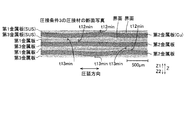
- FIG. 7 and FIG. 8 show a cross-sectional photograph of the pressure-contact material under pressure-contact condition 3 and a part of a cross-sectional photograph of the pressure-contact material under pressure-contact condition 13, respectively.
- FIGS. 7 and 8 three different portions of the same rolling material are stacked in the stacking direction.
- the criteria for evaluation in Table 1 are judged based on whether the ratio of the minimum thickness to the average thickness of the SUS layer in the final product is 70% or more.
- the ratio of the minimum thickness to the average thickness of the SUS layer in the final product of this clad material was 70% (0.175 mm)
- no crack occurred when the ratio of the minimum thickness to the average thickness of the SUS layer in the final product of the clad material is 60 percent (0.150 mm), a crack may occur.
- the thickness ratio R ⁇ 1 shown in Table 1 defines the thickness ratio R ⁇ 2 from another viewpoint (minimum thickness t ⁇ min with respect to the entire cladding material).
- the thickness ratio R ⁇ 2 is a ratio of the thickness of the minimum thickness t ⁇ min to the average thickness t ⁇ avg of the SUS plate immediately after clad rolling.
- the thickness ratios R ⁇ 1 and R ⁇ 2 shown in Table 1 are ratios of stages in the process of producing the final product. Although the thickness of the entire clad material and the thickness of each layer differ between the stage in the process of making the final product and the final product, theoretically, the ratio of the thickness of each layer to the thickness of the entire clad material does not change. The ratio of the minimum thickness to the average thickness does not change.
- the ratio of the minimum thickness to the average thickness of the SUS layer of the final product is less than 70% even if R ⁇ 2 in the process of making the final product is 70% or more.
- the evaluation of the resulting clad material is x (improper).
- R ⁇ 2 is 85% or more
- the ratio of the minimum thickness to the average thickness of the SUS layer of the final product can surely be 70% or more by further rolling (intermediate rolling and finish rolling) after clad rolling
- the evaluation of the clad material is evaluated as ⁇ (suitable) because of its high property.
- the minimum thickness of the first layer It is believed that the thickness and the minimum thickness of the third layer will be less than 70% of the average thickness of the first layer and the average thickness of the third layer, respectively. Therefore, the pressure contact conditions 1 to 3 are marked with x (not suitable) as the evaluation.
- Rz1 is 22.0% or more (more than 20.8% and 21% or more) in a pressure-welded material which is rolled and joined under a pressure contact load P of 4.4 ⁇ 10 3 N / mm or more under pressure welding conditions 4 to 13.
- R ⁇ 2 was 88.0% or more (more than 83.2% and 84% or more). It is considered that this is because the sufficient pressing load P of 4.4 ⁇ 10 3 N / mm or more suppressed the rolling of each layer so as to cause nonuniform plastic deformation.
- the pressure-welded materials of the pressure-welding conditions 4 to 13 are clad materials as final products.
- the minimum thickness of the first layer and the minimum thickness of the third layer are considered to be 70% or more of the average thickness of the first layer and the average thickness of the third layer, respectively. Therefore, the pressure contact conditions 4 to 13 are marked with ⁇ (appropriate) as the evaluation.
- the values of thickness ratio R ⁇ 1 and thickness ratio R ⁇ 2 of the pressure-welded material subjected to rolling bonding with a pressure-contact load P of 6.7 ⁇ 10 3 N / mm or more under pressure-contacting condition 10 are 6 of pressure-contacting condition 9
- the value was smaller than the values of R ⁇ 1 and R ⁇ 2 of the pressure-welded material which was subjected to the rolling bonding with the pressure-contacting load P of not less than 0 ⁇ 10 3 N / mm.
- the values of R ⁇ 1 and R ⁇ 2 of the pressure-welded material subjected to rolling and joining under pressure welding condition P of 7.8 ⁇ 10 3 N / mm or more under pressure welding condition 13 are 7.3 ⁇ 10 3 N / mm or more of pressure welding condition 12
- the thickness ratio R ⁇ 1 and the thickness ratio R ⁇ 2 of the pressure-welded materials subjected to rolling bonding with the pressure-contacting load P are smaller than the values. The result is considered as follows.
- the force P0 applied to the work roller 103a is represented by the product of the pressure load P and the length L of the roller surface (see the above equation (1)). Therefore, when the length L of the roller surface is constant as in the first embodiment, the press-contact load P and the force P0 applied to the work roller 103a are in a proportional relationship. That is, as the pressing load P increases, the force P0 applied to the work roller 103a also increases. From this point of view, it is considered that the value of the thickness h2 of the pressure-contacting material 130 at the outlet side of the rolling roller 103 fluctuates with the fluctuation of the force P0, and R ⁇ 1 and R ⁇ 2 happen to be small under the influence.
- the thickness h2 of the pressure-contacting material 130 at the outlet side of the rolling roller 103 decreases, the plastic deformation ratio of each layer increases. Accordingly, the uniformity of the thickness h2 of the pressure-contacting material 130 on the outlet side of the rolling roller 103 is difficult to obtain, and the uniformity of the thickness of each layer is also difficult to obtain. As a result, uniformity of thickness h 2, thickness ratio R ⁇ 1 and thickness ratio R ⁇ 2 of pressure-contacting material 130 on the outlet side of rolling roller 103 becomes difficult to obtain, and may show small values or large values. However, although it becomes difficult to obtain uniformity, for example, as can be seen by comparing the result of pressure contact condition 4 with the result of pressure contact condition 13, thickness ratio R ⁇ 1 and thickness ratio R ⁇ 2 themselves are gradually increased by increasing the pressure load. It is getting bigger.
- the change tendency of the value of R ⁇ 1 of the press-contact material to the press-contact load P shown in Table 1 is approximately a linear approximate curve having an inclination of about 0.87 and an intercept of about 17.5 (suitable for data having a simple linear relationship) Can be represented by a straight line).
- the change tendency of the value of R ⁇ 2 of the press-contacting material with respect to the press-contact load P shown in Table 1 can be generally expressed by a linear approximate curve having an inclination of about 3.46 and an intercept of about 69.8. Therefore, there is a positive correlation between the pressure contact load P and the values of R ⁇ 1 and R ⁇ 2 of the pressure contact material, and it can be confirmed that the values of R ⁇ 1 and R ⁇ 2 of the pressure contact material increase as the pressure contact load P increases.
- the degree of corrugation (the size of the corrugation) at the interface is clearly different between the pressure-welded material marked with x (not suitable) and the pressure-welded material marked with ⁇ (suitable) as evaluation.
- the degree of wave of the interface when the minimum thickness to the average thickness is small (the values of thickness ratio R ⁇ 2 and R ⁇ 2 are small) in the pressure contact material, the wave amplitude at the interface becomes large, and as a result, the wave of the interface It is known that the degree increases (more waves). That is, by increasing the pressure contact load, the degree of undulation of the interface is improved.
- a clad material of a comparative example to the inventive example was produced. Specifically, a strip-like Cu plate made of Cu or a Cu alloy and in a state where the structure was sufficiently softened was prepared. In addition, temper rolling was not performed with respect to a strip
- clad welding is performed by rolling and joining using a rolling roller.
- the rolling bonding was performed under the pressure load P of 4.3 ⁇ 10 3 N / mm (pressure contact condition 3 of the first embodiment).
- the thickness change (rolling reduction) of the pressure-contacting material before and after clad rolling in the comparative example was the same as in the inventive example.
- the thicknesses of five places randomly selected in the SUS layer 31 were measured and averaged to obtain an average thickness t2avg of the SUS layer 31.
- the thicknesses of five places randomly selected in the SUS layer 33 were measured and averaged to obtain an average thickness t3avg of the SUS layer 33.
- the five average thicknesses t2avg and five average thicknesses t3avg obtained from the ten test areas are collectively averaged to obtain the average thickness t ⁇ avg of the SUS layer (SUS layers 31 and 33) of the clad material 30. Therefore, the above-mentioned average thickness t ⁇ avg is based on the measured values of the thickness of 100 pieces obtained from the clad material 30.
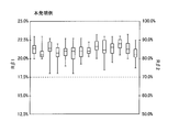
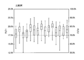
- the results are shown by so-called box and whisker plots.
- the box and whisker plot of the inventive example and the box and whisker plot of the comparative example are shown in FIG. 9 and FIG. 10, respectively.
- the clad material of the example of the present invention it has been confirmed that the occurrence of a place where the thickness is excessively small in the SUS layer (the first layer and the third layer) made of stainless steel is suppressed. Further, it was confirmed that the first quartile of R ⁇ 1 in each clad material is 20% or more, and the first quartile of R ⁇ 2 is 80.0% or more. From this, it has been confirmed that it is possible to reliably suppress the occurrence of a place where the thickness is excessively small in the SUS layer in many clad materials.
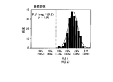
- the standard deviation ⁇ of R ⁇ 1 in the clad material of the example of the present invention was 1.0% (1.5% or less), and the variation in R ⁇ 1 was small. As a result, it has been confirmed that it is possible to suppress the occurrence of variations in properties such as mechanical strength in products (chassis and the like) manufactured from the clad material of the example of the present invention.
- the standard deviation ⁇ of R ⁇ 1 in the clad material of the comparative example was 1.7% (value exceeding 1.5%), and the variation of R ⁇ 1 was large. As a result, it has been confirmed that variations in characteristics such as mechanical strength are likely to occur in products (chassis and the like) manufactured from the clad material of the comparative example.
- R.alpha.1 and R.alpha.2 in the pressure-contacting material of pressure-contact condition 4 of the first embodiment (made with pressure-contacting load within the scope of the present invention (claim 4)) and pressure-contacting material of pressure-contacting condition 6 (claim 4 of the present invention) R.alpha.1 and R.alpha.2 in the pressure contact load within the range of the above were respectively the same value. Therefore, even if R.beta.1 and R.beta.2 are measured in the same manner as the second embodiment using the pressure welding material of the pressure welding condition 4, the measurement in the second embodiment performed using the pressure welding material of the pressure welding condition 6 It can be inferred that results substantially similar to R ⁇ 1 and R ⁇ 2 can be obtained.
- the minimum thickness in the stacking direction of the first layer and the minimum thickness in the stacking direction of the third layer are respectively the first layer If the average thickness in the stacking direction and the average thickness in the stacking direction of the third layer are 70% or more and less than 100% (the thickness ratio R ⁇ 2 is 70% or more and less than 100%), welding is performed when welding the cladding material to another member While being able to suppress that intensity
- the pressure contact condition 3 pressure contact load: 4.3 ⁇ 10 3 N / mm
- R ⁇ 2 minimum thickness of the SUS layer
- the pressure contact condition 6 pressure contact load: 4.9 ⁇ 10 3 N / mm
- the thickness ratio R ⁇ 2 after finish rolling was determined for the examples. Then, as shown in FIGS.
- the thickness ratio R ⁇ 2 after finish rolling is 70% or more in all the test materials, while in the comparative example, the thicknesses after finish rolling in all the test materials The portion where the ratio R ⁇ 2 was less than 70% occurred. From this, in the clad material manufactured under the pressure contact conditions 1 and 2 having the thickness ratio R ⁇ 2 smaller than the pressure contact condition 3 (pressure contact load: 4.3 ⁇ 10 3 N / mm), the thickness ratio R ⁇ 2 (SUS after finish rolling) If the minimum thickness of the layer is smaller than the pressure contact condition 3, it can easily be conceived. Therefore, in Table 1, since the pressure contact condition 3 is x, both the pressure contact conditions 1 and 2 are x.
- the crystal grain size of the Cu layer was measured based on the comparative method of JIS H 0501 for the clad materials of the present invention example and the comparative example in the second embodiment. Further, by performing a tensile strength test according to JIS Z 2241 on the clad materials of the invention examples and comparative examples, the tensile strength (force at break) and 0.2% proof stress as mechanical strength are obtained. (A force at an elongation of 0.2%) and an elongation as a processability ((Length at break-Length before test) / Length before test) x 100 (%)) were measured. Moreover, the relative magnetic permeability of the clad material of this invention example and a comparative example was measured as a magnetic characteristic. The measurement results are shown in Table 2.
- the thickness of the pressure-welded material (pressure-welded material 130) after clad rolling is a clad material (clad material 30) as a final product.
- clad material 30 As a final product of a thickness level, such as 1.0 mm or less, 0.5 mm or less, 0.3 mm or less, and further 0.2 mm or less.
- a thickness level such as 1.0 mm or less, 0.5 mm or less, 0.3 mm or less, and further 0.2 mm or less.
- temper rolling In order to perform clad rolling easily and reliably, it is preferable to perform temper rolling. Further, in order to reduce the product-to-product difference in the thickness of the clad material, it is preferable to perform intermediate rolling and finish rolling.
Landscapes
- Engineering & Computer Science (AREA)
- Mechanical Engineering (AREA)
- Chemical & Material Sciences (AREA)
- Materials Engineering (AREA)
- Metallurgy (AREA)
- Organic Chemistry (AREA)
- Physics & Mathematics (AREA)
- Thermal Sciences (AREA)
- Crystallography & Structural Chemistry (AREA)
- Pressure Welding/Diffusion-Bonding (AREA)
- Laminated Bodies (AREA)
- Metal Rolling (AREA)
Abstract
このクラッド材(30)は、ステンレス鋼により構成される第1層(31)と、CuまたはCu合金により構成され、第1層に圧延接合された第2層(32)と、ステンレス鋼により構成され、第2層の第1層とは反対側に圧延接合された第3層(33)と、を備える。クラッド材は、全体厚みが1mm以下であり、積層方向に沿った断面視において、第1層の積層方向における最小厚みおよび第3層の積層方向における最小厚みは、それぞれ、第1層の積層方向における平均厚みおよび第3層の積層方向における平均厚みの70%以上100%未満である。
Description
この発明は、クラッド材およびそのクラッド材の製造方法に関する。
従来、ステンレス鋼により構成される第1層および第3層と、第1層および第3層の間に配置されたCuまたはCu合金により構成された第2層とが圧延接合されたクラッド材が、たとえば、特開2005-219478号公報に開示されている。
特開2005-219478号公報に開示されるクラッド板は、銅または銅合金からなる中心層(第2層)の両面にステンレス鋼からなる被覆層(第1層、第3層)がそれぞれ圧延接合され、被覆層はNbなどからなるバリヤ層を介して中心層に接合されている。また、クラッド板は、熱間圧延、温冷間圧延などの減厚加工により圧延接合されている。
ここで、本願発明者は、種々検討した結果、特開2005-219478号公報に開示されたクラッド材は、ステンレス鋼により構成される第1層または第3層に厚みが過度に小さい箇所が生じる場合があり、その結果、クラッド材を他の部材に溶接する際に溶接強度が低下する場合が生じること、および、クラッド材の機械的強度のばらつきが生じる場合があることを発見した。
本発明は、上記のような課題を解決するためになされたものであり、本発明の1つの目的は、クラッド材を他の部材に溶接する際に溶接強度が低下すること、および、クラッド材の機械的強度のばらつきが生じることを抑制することが可能なクラッド材およびそのクラッド材の製造方法を提供することである。
本願発明者は、上記課題を解決するために鋭意検討した結果、第1層の積層方向における最小厚みおよび第3層の積層方向における最小厚みが、それぞれ、狙い厚み(目標値)に対して過度に小さいことに起因して、クラッド材を他の部材に溶接する際に溶接強度が低下する場合が生じること、およびクラッド材の機械的強度のばらつきが生じることをさらに見出した。このような知見に基づいて、本発明を完成させた。つまり、本発明の第1の局面によるクラッド材は、ステンレス鋼により構成される第1層と、CuまたはCu合金により構成され、第1層に圧延接合された第2層と、ステンレス鋼により構成され、第2層の第1層とは反対側に圧延接合された第3層と、を備え、全体厚みが1mm以下であり、積層方向に沿った断面視において、第1層の積層方向における最小厚みおよび第3層の積層方向における最小厚みは、それぞれ、第1層の積層方向における平均厚みおよび第3層の積層方向における平均厚みの70%以上100%未満である。
なお、「ステンレス鋼」とは、Fe(鉄)を主成分として50質量%以上含むとともに、少なくともCr(クロム)を10.5質量%以上さらに含む合金を意味する。また、「Cu合金」とは、Cu(銅)を主成分として50質量%以上含む合金を意味する。また、「第1層の積層方向における最小厚み」および「第3層の積層方向における最小厚み」とは、それぞれ、積層方向に沿った断面視において、クラッド材の圧延方向に沿った所定の長さの範囲における第1層の厚みの最小値および第3層の厚みの最小値を意味する。
本発明の第1の局面によるクラッド材では、上記のように、積層方向に沿った断面視において、第1層の積層方向における最小厚みおよび第3層の積層方向における最小厚みは、それぞれ、第1層の積層方向における平均厚みおよび第3層の積層方向における平均厚みの70%以上100%未満である。このようにクラッド材を構成すれば、第1層および第3層の積層方向における厚みが均等化されるので、第1層および第3層に厚みが過度に小さい箇所(平均厚みの70%未満の箇所)が生じるのを抑制することができる。この結果、クラッド材を他の部材に溶接する際に溶接強度が低下すること、およびクラッド材の機械的強度のばらつきが生じることを抑制することができる。したがって、たとえば、クラッド材を他の部材に溶接する場合において、第1層の厚みまたは第3層の厚みが過度に小さい箇所に他の部材が溶接されるのを抑制することができるので、十分な溶接が行われずに溶接強度が低下するのを抑制することができる。また、クラッド材の機械的強度のばらつきが生じることができるため、クラッド材から作製される製品に機械的強度などの特性のばらつきが生じるのを抑制することができる。なお、この構成による効果は、全体厚みが1mm以下と小さく、かつ、第1層および第3層の平均厚みが小さい場合(たとえば0.20mm以下)に特に有効である。また、第1層および第3層に厚みが過度に小さい箇所が生じるのを抑制することにより、圧延した際に第1層および第3層に破れまたはピンホールが生じ、第2層が被覆されない箇所が生じることを抑制できる。
また、第1の局面によるクラッド材は、上記のように、ステンレス鋼により構成される第1層と、CuまたはCu合金により構成され、第1層に圧延接合された第2層と、ステンレス鋼により構成され、第2層の第1層とは反対側に圧延接合された第3層と、を備える。このようにクラッド材を構成すれば、ステンレス鋼により構成される第1層および第3層により機械的強度および耐食性を確保しつつ、CuまたはCu合金により構成される第2層により導電性および熱伝導性を確保することができる。この結果、電池用の導電部材およびヒートシンクを兼ねるシャーシなどに好適なクラッド材を提供することができる。
上記第1の局面によるクラッド材において、好ましくは、第1層の最小厚みのクラッド材の厚みに対する百分率の標準偏差、および、第3層の最小厚みのクラッド材の厚みに対する百分率の標準偏差は、1.5%以下である。このようにクラッド材を構成すれば、第1層および第3層の積層方向における最小厚みが一層均等化されるので、第1層および第3層に厚みが過度に小さい箇所(平均厚みの70%未満の箇所)が生じるのを一層抑制することができる。この結果、ステンレス鋼により構成される第1層または第3層に厚みが過度に小さい箇所が生じるのを一層抑制することができる。したがって、上記したような溶接強度の低下を一層抑制することができる。また、上記したようなクラッド材から作製される製品の特性のばらつきを一層抑制することができる。なお、この構成による効果は、第1層および第3層の平均厚みが小さい場合に特に有効である。
上記第1の局面によるクラッド材において、好ましくは、第1層および第3層は、共にオーステナイト系ステンレス鋼により構成されている。このように構成すれば、オーステナイト系ステンレス鋼とCuまたはCu合金とが共に非磁性であることにより、クラッド材全体を非磁性にすることができる。これにより、たとえば、ヒートシンクを兼ねるシャーシにクラッド材を用いる際に、シャーシが磁化することで他部品(たとえば電子部品)に悪影響を与えないようにすることができる。
本発明の第2の局面によるクラッド材の製造方法は、ステンレス鋼により構成された第1金属板と、CuまたはCu合金により構成された第2金属板と、ステンレス鋼により構成された第3金属板と、をこの順で積層させた状態で圧延して接合するクラッド圧延を含み、4.4×10³N/mm以上の圧接荷重によりクラッド圧延することにより、ステンレス鋼により構成される第1層と、CuまたはCu合金により構成され、第1層に圧延接合された第2層と、ステンレス鋼により構成され、第2層の第1層とは反対側に圧延接合された第3層と、を備え、全体厚みが1mm以下であり、積層方向に沿った断面視において、第1層の積層方向における最小厚みおよび第3層の積層方向における最小厚みが、それぞれ、第1層の積層方向における平均厚みおよび第3層の積層方向における平均厚みの70%以上100%未満となるクラッド材を作製する。なお、本発明における「圧接荷重」とは、クラッド圧延の際に、圧延材(本発明では、第1金属板、第2金属板および第3金属板)から圧延ローラに作用する力の合力で、かつ、単位長さ当たりの力である。この圧接荷重は、圧延荷重または圧下力と称されることもある。
本発明の第2の局面によるクラッド材の製造方法では、上記のように、ステンレス鋼により構成された第1金属板と、CuまたはCu合金により構成された第2金属板と、ステンレス鋼により構成された第3金属板と、をこの順で積層させた状態で4.4×10³N/mm以上の圧接荷重によりクラッド圧延する。これにより、4.4×103N/mm以上の十分な圧接荷重によりクラッド圧延が行われるので、ステンレス鋼により構成された第1金属板および第3金属板とCuまたはCu合金により構成された第2金属板との延性の違いに起因して各層が不均一に塑性変形するように圧延されるのを抑制することができる。この結果、クラッド材において、第1層の積層方向の厚みおよび第3層の積層方向の厚みが共に不均一になるのを抑制することができるので、ステンレス鋼により構成される第1層または第3層に厚みが過度に小さい箇所が生じるのを抑制することができる。また、第1層および第3層に厚みが過度に小さい箇所が生じるのを抑制することにより、圧延した際に第1層および第3層に破れまたはピンホールが生じ、第2層が被覆されないことを抑制できる。
上記第2の局面によるクラッド材の製造方法において、好ましくは、圧接荷重を4.9×10³N/mm以上とする。このように構成すれば、より十分な圧接荷重によりクラッド圧延を行うことができるので、各層が不均一に塑性変形するように圧延されるのをより抑制することができる。
上記第2の局面によるクラッド材の製造方法において、好ましくは、準備する第2金属板を、焼鈍処理を行った後に調質圧延されて加工硬化されたものとする。このように構成すれば、CuまたはCu合金により構成される第2金属板として、内部応力(歪み)が蓄積されて機械的強度(0.2%耐力等)が向上された第2金属板を用いることができる。これにより、ステンレス鋼により構成される第1金属板および第3金属板と比べて機械的強度が低い第2金属板の機械的強度を、第1金属板および第3金属板の機械的強度に近づけることができる。この結果、機械的強度を近づけた金属板同士によりクラッド圧延を行うことができるので、各層がより均一に塑性変形するように圧延されるため、第1金属板と第2金属板と第3金属板とを十分に接合させることができるとともに、各層の厚みを高精度に形成することができる。
この場合、好ましくは、準備する第2金属板を、調質圧延後の厚みが調質圧延前の厚みの60%以上100%未満になっているものとする。このように構成すれば、準備する第2金属板において、調質圧延後の厚みが調質圧延前の厚みの60%未満であることに起因して、準備する第2金属板に内部応力(歪み)が過度に蓄積されるのを抑制することができる。これにより、大きな内部応力(歪み)に起因して第2層(第2金属板)の結晶が粗大化するのを抑制することができるので、第2層に起因してクラッド材の伸び(加工性)が低下するのを抑制することができる。
本発明によれば、上記のように、クラッド材を他の部材に溶接する際に溶接強度が低下すること、および、クラッド材の機械的強度のばらつきが生じることを抑制することが可能なクラッド材およびそのクラッド材の製造方法を提供することができる。
以下、本発明を具体化した実施形態を図面に基づいて説明する。
(携帯機器の構成)
まず、図1および図2を参照して、本発明の一実施形態によるクラッド材30をシャーシ3として用いた携帯機器100の概略的な構成について説明する。
まず、図1および図2を参照して、本発明の一実施形態によるクラッド材30をシャーシ3として用いた携帯機器100の概略的な構成について説明する。
本実施形態による携帯機器100では、図1に示すように、上側筐体1aと、ディスプレイ2と、シャーシ3と、基板4と、電池5と、下側筐体1bとを備えている。ディスプレイ2と、シャーシ3と、基板4および電池5とは、上方(Z1側)からこの順に下側筐体1b内に配置されている。そして、下側筐体1bは、上方から上側筐体1aに覆われている。
ディスプレイ2は、液晶ディスプレイや有機ELディスプレイなどからなり、Z1側の上面に画像を表示する機能を有する。
シャーシ3は、携帯機器100の機械的強度を確保する機能と、ディスプレイ2、基板4(電子部品4a)および電池5からの熱を外部に放出する機能とを有している。つまり、シャーシ3はヒートシンクを兼ねる。また、シャーシ3には、携帯機器100の図示しない部材が溶接されている。
下側筐体1bのX1側には基板4が、X2側には電池5が、それぞれ配置されている。基板4のZ1側の上面には、アプリケーションを駆動させるためのCPU(Central Processing Unit)などの電子部品4aが配置されている。
(シャーシ(クラッド材)の構成)
シャーシ3は、図2に示すように、ステンレス鋼により構成されるSUS層31と、CuまたはCu合金により構成されるCu層32と、ステンレス鋼により構成されるSUS層33とがこの順に積層された3層構造のクラッド材30から構成されている。Cu層32は、SUS層33のZ1側の面(上面)に圧延接合されているとともに、SUS層31のZ2側の面(下面)に圧延接合されている。なお、SUS層31とCu層32との界面およびCu層32とSUS層33との界面において、互いの層は拡散焼鈍により互いの層が原子間接合を形成して強固に接合している。また、SUS層31およびSUS層33に、携帯機器100の図示しない部材が溶接されている。なお、SUS層31、Cu層32およびSUS層33は、それぞれ、特許請求の範囲の「第1層」、「第2層」および「第3層」の一例である。
シャーシ3は、図2に示すように、ステンレス鋼により構成されるSUS層31と、CuまたはCu合金により構成されるCu層32と、ステンレス鋼により構成されるSUS層33とがこの順に積層された3層構造のクラッド材30から構成されている。Cu層32は、SUS層33のZ1側の面(上面)に圧延接合されているとともに、SUS層31のZ2側の面(下面)に圧延接合されている。なお、SUS層31とCu層32との界面およびCu層32とSUS層33との界面において、互いの層は拡散焼鈍により互いの層が原子間接合を形成して強固に接合している。また、SUS層31およびSUS層33に、携帯機器100の図示しない部材が溶接されている。なお、SUS層31、Cu層32およびSUS層33は、それぞれ、特許請求の範囲の「第1層」、「第2層」および「第3層」の一例である。
クラッド材30のZ方向の厚みt1は特に限定されない。なお、本実施形態では、携帯機器100の軽量化やコンパクト化を考慮してZ方向の厚みの増加を抑制するために、シャーシ3の厚みt1は、好ましくは1mm以下であり、より好ましくは0.5mm以下である。また、シャーシ3の機械的強度を確保するため、および製造が困難になることを抑制するために、シャーシ3の厚みt1は、好ましくは0.03mm以上、より好ましくは0.05mm以上、さらに好ましくは0.1mm以上であるのが好ましい。また、放熱性の観点からCu層32がSUS層(31、33)よりも厚みが大きいほうが好ましい。しかしながら、Cu層32の厚みが大きすぎるとSUS層(31、33)の厚みが小さくなり、Cu層32に圧延接合したときに破れまたはピンホールが生じるおそれがある。その結果、Cu層32がSUS層(31、33)で被覆されない箇所が生じるおそれがある。そのため、層厚比(SUS層:Cu層:SUS層)は、SUS層の厚みを1としたときにCu層の厚みが2以上8以下(1:2:1から1:8:1)であるのが好ましい。
SUS層31およびSUS層33を構成するステンレス鋼は、ステンレス鋼であれば、オーステナイト系、フェライト系およびマルテンサイト系など、特に限定されない。ここで、本実施形態では、電子部品4a(図1参照)を備える携帯機器100においてシャーシ3が磁性を帯びるのは好ましくない。そこで、SUS層31およびSUS層33を構成するステンレス鋼は、好ましくは、オーステナイト系ステンレス鋼であり、いわゆるSUS300系(JIS規格)のオーステナイト系ステンレス鋼により構成されるのがより好ましい。
さらに、SUS層31およびSUS層33を構成するステンレス鋼は、オーステナイト系ステンレス鋼のうち、C(炭素)の含有量が少なく、磁性をより帯びにくいSUS316L(JIS規格)であるのが特に好ましい。なお、SUS316Lとは、18質量%のCrと、12質量%のNiと2.5質量%のMoと、Cを含む不可避不純物等と、残部Fe(鉄)とを含有するSUS316(JIS規格)において、Cの含有量を低下させたオーステナイト系ステンレス鋼である。また、SUS層31とSUS層33とは、同じ組成に限定されないが、圧延の安定性などを考慮して同じ組成を有するステンレス鋼により構成されるのが好ましい。
Cu層32は、C1000系(JIS規格)のCuまたはC2000系(JIS規格)などのCu合金により構成されている。なお、Cuとしては、いわゆる、無酸素銅、りん脱酸銅、タフピッチ銅などがある。また、Cu合金としては、結晶の粗大化を抑制するためにC1050(JIS規格)のZr-Cu合金などが好ましい。なお、Cu層32を構成するCuまたはCu合金は、一般的に、SUS層31およびSUS層33を構成するステンレス鋼よりも熱伝導性が高いとともに、延性が大きい。また、JIS H 0501の比較法により測定されるCu層32(CuまたはCu合金)の結晶粒度は、0.150mm以下であるのが好ましく、Cu層32の伸び(延性)が低下するのを抑制することができる。
また、本実施形態のクラッド材30では、SUS層31および33に、それぞれ、圧延方向に沿って厚みt2およびt3にばらつきが生じている。この結果、SUS層31および33には、それぞれ、他の部分の厚みt2およびt3よりも小さな最小厚みt2minおよびt3minが存在している。一方、Cu層32の厚みt4には、ばらつきがほとんど生じていない。この結果、厚みt2およびt3にばらつきが生じている場合には、積層方向(Z方向)に沿った断面視において、クラッド材30の界面が波状になる。なお、図2では、界面の波状を誇張して図示している。
ここで、本実施形態では、クラッド材30では、積層方向(Z方向)に沿った断面視において、SUS層31の積層方向における最小厚みt2minおよびSUS層33の積層方向における最小厚みt3minは、それぞれ、SUS層31の積層方向における平均厚みt2avgおよびSUS層33の積層方向における平均厚みt3avgの70%以上100%未満である。
ここで、SUS層31の積層方向における最小厚みt2minは、クラッド材30の圧延方向における所定の範囲(長さ)におけるSUS層31の最小の厚みt2である。同様に、SUS層33の積層方向における最小厚みt3minは、クラッド材30の圧延方向における所定の範囲(長さ)におけるSUS層33の最小の厚みt3である。ここで、クラッド材30における上記の所定の範囲(長さ)は、波状に形成される界面の波の1波長以上の範囲であれば特に限定されないが、測定の信頼性の観点から少なくとも15mm程度であるのがよい。また、SUS層31の積層方向における平均厚みt2avgは、クラッド材30におけるSUS層31の厚みt2の平均である。同様に、SUS層33の積層方向における平均厚みt3avgは、クラッド材30におけるSUS層33の厚みt3の平均である。なお、平均厚みt2avgおよびt3avgは、クラッド材30のたとえば上記の所定の範囲(長さ)において、SUS層31および33の複数箇所(たとえば10箇所以上)における厚みt2およびt3をそれぞれ無作為に測定し、測定した複数の厚みt2およびt3の平均をそれぞれ算出することによって求めるのがよい。一方、Cu層32の厚みt4は、平均厚みt4avg(ばらつきがほとんど生じていないため、以下、単に「t4」と表記する。)として、上記のSUS層31および33の平均厚みt2avgおよびt3avgと同様な方法で求めるのがよい。
また、SUS層31の最小厚みt2minのクラッド材30の厚みt1に対する百分率の標準偏差(%)、および、SUS層33の最小厚みt3minのクラッド材30の厚みt1に対する百分率の標準偏差(%)は、共に、1.5%以下であるのが好ましく、1.2%以下であるのがより好ましい。なお、標準偏差を求める際には、より多くの箇所(たとえば100箇所以上)の最小厚みt2minおよびt3minをそれぞれ取得するのが好ましい。
ここで、SUS層31とSUS層33とにおいて、各層を構成するステンレス鋼の組成(材質)と、クラッド材30の厚み(t1)に対する平均厚み(t2avg、t3avg)の厚み比率(t2avg/t1、t3avg/t1)とが共に等しい場合には、SUS層31とSUS層33とにおいて、最小厚みおよび最小厚みのばらつきが同等になると考えられる。したがって、この場合、SUS層31とSUS層33とのデータを合算して評価して、一対のSUS層の最小厚みおよび標準偏差として扱うことが可能である。
また、クラッド材30におけるSUS層31の平均厚みt2avg、Cu層32の厚みt4およびSUS層33の平均厚みt3avgの比率(t2avg:t4:t3avg)は、特に限定されない。なお、クラッド圧延等における延び具合をZ方向の両側で均等化させるために、共にステンレス鋼により構成されるSUS層31の平均厚みt2avgとSUS層33の平均厚みt3avgとは、略等しい方が好ましい。
なお、シャーシ3において要求される特性(熱伝導性および機械的強度)に応じて厚み比率を異ならせるのが好ましい。たとえば、シャーシ3において機械的強度が特に要求される場合には、機械的強度の大きいステンレス鋼により構成されるSUS層31の平均厚みt2avgおよびSUS層33の平均厚みt3avgを大きくするのが好ましい。なお、クラッド材30の機械的強度を確実に確保するためには、Cu層32の厚みt4は、クラッド材30の厚みt1の60%以下であるのが好ましい。一方、シャーシ3において熱伝導性が特に要求される場合には、Cu層32の厚みt4を大きくするのが好ましい。なお、クラッド材30の熱伝導性を確実に確保するためには、Cu層32の厚みt4は、クラッド材30の厚みt1の33%以上であるのが好ましい。また、クラッド材30の伸びは、プレス加工性等の観点から、8%以上であるのが好ましく、10%以上であるのがより好ましい。
(シャーシ(クラッド材)の製造方法の概要)
次に、図2~図6を参照して、本発明の一実施形態によるシャーシ3を構成するクラッド材30の製造方法を説明する。
次に、図2~図6を参照して、本発明の一実施形態によるシャーシ3を構成するクラッド材30の製造方法を説明する。
まず、図3に示すように、CuまたはCu合金により構成された帯状のCu板132を準備する。そして、Cu板132に対して、Cu板132を構成するCuまたはCu合金の再結晶温度(たとえば、220℃)を超える温度に内部が設定された焼鈍炉101を用いて軟化焼鈍を行う。これにより、Cu板132は加工硬化による内部の歪みが取り除かれて組織が十分に軟化された状態となる。
そして、軟化焼鈍を経たCu板132に対して、圧延ローラ102を用いて調質圧延を行う。調質圧延により、Cu板132は、内部応力(歪み)が蓄積されて加工硬化される。また、調質圧延のパス数は、適宜選択可能である。
なお、調質圧延において、調質圧延後のCu板132における厚みt14が、調質圧延前のCu板132における厚みt14の60%以上100%未満になるように圧延するのが好ましい。これにより、後述するクラッド圧延時に、機械的強度が大きく延性の低いステンレス鋼により構成されるSUS板131および133と、機械的強度が小さく延性の高いCuまたはCu合金により構成されるCu板132との延性を近づけることが可能である。
なお、調質圧延後のCu板132における厚みt14を、調質圧延前のCu板132における厚みt14の60%以上にすることにより、クラッド材30のCu層32の結晶の粗大化を容易に抑制することが可能である。これらにより、準備するCu板132を、焼鈍処理を行った後に調質圧延されて加工硬化されたものとすることが可能である。
また、図4に示すように、焼鈍処理後に調質圧延を経た帯状のCu板132に加えて、ステンレス鋼により構成される帯状のSUS板131および帯状のSUS板133を準備する。また、SUS板131および133は、共に十分に焼鈍されている。なお、SUS板131の厚みと、調質圧延を経たCu板132の厚みと、SUS板133の厚みとは、作製されるクラッド材30におけるSUS層31とCu層32およびSUS層33の厚み比率(t2avg:t4:t3avg)に合わせて適宜選択される。
そして、十分に焼鈍されたSUS板131と、焼鈍処理後に調質圧延を経たCu板132と、十分に焼鈍されたSUS板133とを、この順に積層した状態で、圧延ローラ103を用いて圧延して接合するクラッド圧延を行う。これにより、SUS板131と、Cu板132と、SUS板133とがこの順に積層された状態で互いに接合(圧延接合)された、たとえば1.0mm以下または0.5mm以下の厚みの圧接材130が作製される。また、クラッド圧延のパス数は、適宜選択可能である。
圧延ローラ103は、図5に示すように、一対のワークローラ103aおよび103bと、ワークローラ103aおよび103bの軸をそれぞれ保持する4個の軸受け103cと、たとえばZ1側のワークローラ103aの軸受け103cに取り付けられる一対のロードセル103dとを含んでいる。一対のロードセル103dは、ワークローラ103aに作用する力(合力)に起因する歪を検出することによって、SUS板131、Cu板132およびSUS板133(圧延材)からワークローラ103aに作用する力(合力)P0(N)を検出する機能を有している。
クラッド圧延を行う場合に、最初に圧接荷重を決定することは重要となる。「板圧延」(日本塑性加工学会 編、コロナ社 1993年2月15日初版)に記載されているように、板厚制御は、用いる圧延機および圧延方法によって異なる。そのため、所望の板厚にするために、圧延機や圧延方法を検討する必要がある。一方で、圧延ローラの出口側における圧接材の厚みは、圧接荷重、板幅、圧下力関数、変形抵抗等の値から計算することが可能である。そのため、圧接荷重を決定することにより、用いる圧延機に合わせた所望の板厚にするための諸条件を設定することが可能になる。また、板厚は、圧接荷重による圧延機の変形と圧延機のロール設定位置との和と等しい。そこで、所望の板厚にするために、ロール設定位置を変更することにより調整することができる。
また、「板材の圧延」(コロナ社、1960年10月25日初版)に記載されているように、合理的な圧延計画には圧接荷重が関係している。圧延前の肉厚、ロール半径等の諸条件から圧接荷重を計算することができるため、圧接荷重を予め決めておくことによって、他の諸条件を規定しなくとも合理的な圧延計画を立てることが可能になる。
本実施形態の製造方法では、クラッド圧延における圧接荷重Pが4.4×10³N/mm以上になるように設定されている。ここで、圧接荷重Pは、ワークローラ103a(103b)の軸方向(圧延方向および積層方向と直交する方向で「幅方向」ともいう)におけるローラ面の長さをL(mm)とした際に、ワークローラ103aに加えられる力P0を用いて、下記の式(1)から求めることが可能である。
P=P0/L・・・(1)
P=P0/L・・・(1)
また、圧接荷重P(N/mm)は、下記の式(2)から見積もりとして求めることが可能である。
P=Qp・k・√(R・(h1-h2))/L・・・(2)
P=Qp・k・√(R・(h1-h2))/L・・・(2)
なお、上記式(2)において、圧下力関数(理想的な変形と比較した倍率)をQp、平均変形抵抗(幅方向の変形を無視した場合の2次元変形状態において、圧延ローラ間における変形するために要する平均の応力)をk(N/mm2)とする。また。図6を参照して、ワークローラ103a(103b)の半径をR(mm)、圧延ローラ103の入口側におけるSUS板131、Cu板132およびSUS板133(圧延材)の合計厚みをh1(mm)、圧延ローラ103の出口側における圧接材130の厚みをh2(mm)とする。
ここで、ワークローラ103a(103b)の半径を大きくする、ワークローラ103a(103b)と圧延材との動摩擦係数を大きくする、クラッド圧延における圧下率(=(h1-h2)/h1)を大きくする、圧延材に加えられる圧延方向に沿った力(張力)を小さくする、圧延材の搬送速度を小さくすることなどを適切に組み合わせることによって、圧接荷重Pを大きくすることが可能である。なお、連続的にクラッド圧延を行う場合には、圧接速度(搬送速度)または張力を調整することによって、連続的にクラッド圧延しつつ圧接荷重Pを調整することが可能である。
また、最終製品のクラッド材30(図2参照)においてSUS層31の厚みt2およびSUS層33の厚みt3に過度に小さい箇所が生じるのを抑制するためには、圧接荷重Pは、4.9×10³N/mm以上であるのが好ましく、6.0×103N/mm以上であるのがより好ましく、6.8×103N/mm以上であるのがさらに好ましい。一方、連続的にクラッド圧延を行う場合には、圧接速度が小さいと、クラッド材30のタクトタイムが増長するので好ましくない。このため、タクトタイムの短縮を優先する場合には、圧接荷重Pを4.4×103N/mm以上とし、かつ、4.4×103N/mm近傍の値とするのが好ましい。
また、図4に示すように、クラッド圧延直後の圧接材130では、SUS板131の厚みt12およびSUS板133の厚みt13に、それぞれ、圧延方向に沿ってばらつきが生じている。この結果、SUS板131および133には、それぞれ、部分的に厚みの差が生じているために最小厚みt12minおよびt13minが存在している。
また、本実施形態の製造方法では、クラッド圧延における圧接荷重Pが4.4×10³N/mm以上になるように設定されている。これにより、圧接材130の積層方向(Z方向)に沿った断面視において、SUS板131の積層方向における最小厚みt12minおよびSUS板133の積層方向における最小厚みt13minを、それぞれ、SUS板131の積層方向における平均厚みt12avgおよびSUS板133の積層方向における平均厚みt13avgの84%以上100%未満にすることが可能である。
これにより、クラッド圧延後に更なる圧延(後述する中間圧延および仕上げ圧延)を行うことによって、SUS板131の厚みt12およびSUS板133の厚みt13の圧延方向に沿ったばらつきがさらに大きくなったとしても、最終製品としてのクラッド材30における、SUS層31の最小厚みt2minおよびSUS層33の最小厚みt3minを、それぞれ、平均厚みt2avgおよび平均厚みt3avgの70%以上100%未満にすることが可能である。
なお、SUS板131および133の平均厚みt12avgおよびt13avgは、クラッド材の圧延方向における所定の範囲(長さ)から求めてもよい。この所定の範囲(長さ)は、波状に形成される界面の波の1波長以上の範囲であれば特に限定されないが、測定の信頼性の観点から少なくとも15mm程度であるのがよい。また、SUS板131の平均厚みt12avgは、圧接材130におけるSUS板131の厚みt12の平均であり、SUS板133の平均厚みt13avgは、圧接材130におけるSUS板133の厚みt13の平均である。
その後、必要に応じて、端部切断機104を用いて圧接材130の幅方向の端部を切断することによって、圧接材130の幅方向の長さを調整してもよい。そして、圧接材130に対して、圧延ローラ105を用いて中間圧延を行うことにより、圧接材130の厚みを調整する。これにより、圧接材130(クラッド材30)毎の厚みのばらつきを小さくすることが可能である。また、中間圧延のパス数は、適宜選択可能である。
そして、SUS板131を構成するステンレス鋼の再結晶温度を超える温度に内部が設定された焼鈍炉106を用いて拡散焼鈍を行う。この際、焼鈍に起因するCu板132の結晶粒度の粗大化を抑制するために、850℃以上1000℃以下の温度条件下で拡散焼鈍を行うのが好ましい。これにより、SUS板131、Cu板132およびSUS板131のすべてが材質に応じて組織が軟化された状態となる。また、SUS板131とCu板132との界面およびCu板132とSUS板133との界面において、拡散処理により互いの層が原子間接合を形成して強固に接合する。
その後、拡散焼鈍後の圧接材130の厚みを調整するために、仕上げ圧延が行われる。この結果、図2に示すSUS層31と、SUS層31に圧延接合されたCu層32と、Cu層32のSUS層31とは反対側に圧延接合されたSUS層33とを備えるクラッド材30が作製される。
その後、クラッド材30に対して、必要に応じて、形状矯正、スリット切断、プレス(打抜き)加工等が適宜行われる。その結果、図2に示す、クラッド材30から構成されるシャーシ3が作製される。
本実施形態では、図4に示すように、少なくともクラッド圧延から仕上げ工程のスリット切断までの工程を連続的に行うように構成されているため、クラッド材30のタクトタイムを効果的に短縮することが可能である。なお、本発明の製造方法は、クラッド圧延から仕上げ工程のスリット切断までの工程を連続的に行う構成に限定されない。
なお、クラッド圧延後の圧接材130に対して圧延(一般的な冷間圧延)を行うと、その圧下率に対応して各層の平均厚みが小さくなるが、各層の平均厚みの比率は実質的に同等であり変化しない。この観点に基づいて、上記したクラッド材30のSUS層31の平均厚みt2avgとして、クラッド材30の厚みt1(図2参照)に、準備したSUS板131、Cu板132およびSUS板133の合計の厚み(=t12+t13+t14)に対する準備したSUS板131の厚みt12の比率(=t12/(t12+t13+t14))を乗すること(=t1×t12/(t12+t13+t14))により取得してもよい。同様に、上記したクラッド材30のSUS層33の平均厚みt3avgとして、クラッド材30の厚みt1に、準備したSUS板131、Cu板132およびSUS板133の合計の厚みに対する準備したSUS板133の厚みt13の比率(=t13/(t12+t13+t14))を乗すること(=t1×t13/(t12+t13+t14))により取得してもよい。
また、上記した圧接材130のSUS板131の平均厚みt12avgとして、圧接材130の厚みt11に、準備したSUS板131、Cu板132およびSUS板133の合計の厚み(=t12+t13+t14)に対する準備したSUS板131の厚みt12の比率(=t12/(t12+t13+t14))を乗すること(=t11×t12/(t12+t13+t14))により取得してもよい。同様に、上記した圧接材130のSUS板133の平均厚みt13avgとして、圧接材130の厚みt11に、準備したSUS板131、Cu板132およびSUS板133の合計の厚み(=t12+t13+t14)に対する準備したSUS板133の厚みt13の比率(=t13/(t12+t13+t14))を乗すること(=t11×t13/(t12+t13+t14))により取得してもよい。
なお、平均厚みt12avgおよびt13avgとして、対応する層および板の複数箇所(たとえば10箇所以上)における厚みt2、t3、t12およびt13をそれぞれ測定し、それらの平均を算出することによって求めてもよい。
また、本実施形態の製造方法では、拡散焼鈍前(中間圧延後)のCu板132における厚みt14(図4参照)を、軟化焼鈍後(調質圧延前)のCu板132における厚みt14(図3参照)の20%以上にするのが好ましい。これにより、Cu層32(拡散焼鈍後のCu板132)におけるCuまたはCu合金の結晶粒度を150μm以下に小さくすることが可能である。この結果、クラッド材30の伸びが向上されるため加工性を向上させることが可能である。
<本実施形態の効果>
本実施形態では、以下のような効果を得ることができる。
本実施形態では、以下のような効果を得ることができる。
本実施形態では、上記のように、積層方向(Z方向)に沿った断面視において、SUS層31の積層方向における最小厚みt2minおよびSUS層33の積層方向における最小厚みt3minを、それぞれ、SUS層31の積層方向における平均厚みt2avgおよびSUS層33の積層方向における平均厚みt3avgの70%以上100%未満にする。これにより、クラッド材30において、SUS層31およびSUS層33の積層方向における厚みt2およびt3がそれぞれ均等化されるので、SUS層31およびSUS層33に厚みが過度に小さい箇所(平均厚みの70%未満の箇所)が生じるのを抑制することができる。したがって、たとえば、クラッド材30から構成されるシャーシ3を他の部材に溶接する際においてSUS層31の厚みt2またはSUS層33の厚みt3が過度に小さい箇所に他の部材が溶接されるのを抑制することができるので、十分な溶接が行われずに溶接強度が低下するのを抑制することができる。また、クラッド材30から作製される製品(シャーシ3)に機械的強度などの特性のばらつきが生じるのを抑制することができる。また、SUS層31およびSUS層33に厚みが過度に小さい箇所が生じるのを抑制することにより、圧延した際にSUS層31およびSUS層33に破れまたはピンホールが生じ、Cu層32が被覆されないことを抑制できる。
また、本実施形態では、クラッド材30が、ステンレス鋼により構成されるSUS層31と、CuまたはCu合金により構成され、SUS層31に圧延接合されたCu層32と、ステンレス鋼により構成され、Cu層32のSUS層31とは反対側に圧延接合されたSUS層33と、を備える。これにより、クラッド材30において、ステンレス鋼により構成されるSUS層31およびSUS層33により機械的強度および耐食性を確保しつつ、CuまたはCu合金により構成されるCu層32により導電性および熱伝導性を確保することができる。この結果、ヒートシンクを兼ねるシャーシ3に好適なクラッド材30を提供することができる。
また、本実施形態では、好ましくは、SUS層31の最小厚みt2minのクラッド材30の厚みt1に対する百分率の標準偏差、および、SUS層33の最小厚みt3minのクラッド材30の厚みt1に対する百分率の標準偏差が、1.5%以下である。このように構成すれば、SUS層31の積層方向における最小厚みt2minおよびSUS層33の積層方向における最小厚みt3minが一層均等化されるので、SUS層31およびSUS層33に厚みが過度に小さい箇所(平均厚みの70%未満の箇所)が生じるのを一層抑制することができる。この結果、SUS層31またはSUS層33に厚みが過度に小さい箇所が生じるのを一層抑制することができる。したがって、上記したような溶接強度の低下を一層抑制することができる。また、上記したようなクラッド材30から作製されるシャーシ3の特性のばらつきを一層抑制することができる。
また、本実施形態では、好ましくは、SUS層31およびSUS層33を、共にオーステナイト系ステンレス鋼により構成する。このように構成すれば、オーステナイト系ステンレス鋼とCuまたはCu合金とが共に非磁性であることにより、クラッド材30全体を非磁性にすることができる。これにより、クラッド材30からなるヒートシンクを兼ねるシャーシ3が磁化することで電子部品4a等に悪影響を与えないようにすることができる。
また、本実施形態の製造方法では、ステンレス鋼により構成されたSUS板131と、CuまたはCu合金により構成されたCu板132と、ステンレス鋼により構成されたSUS板133と、をこの順で積層させた状態で4.4×10³N/mm以上の圧接荷重Pによりクラッド圧延する。これにより、4.4×103N/mm以上の十分な圧接荷重Pによりクラッド圧延が行われるので、ステンレス鋼により構成されたSUS板131およびSUS板133とCuまたはCu合金により構成されたCu板132との延性の違いに起因して各層が不均一に塑性変形するように圧延されるのを抑制することができる。この結果、クラッド材30において、SUS層31の積層方向の厚みt2およびSUS層33の積層方向の厚みt3が共に不均一になるのを抑制することができるので、積層方向(Z方向)に沿った断面視において、SUS層31の積層方向における最小厚みt2minおよびSUS層33の積層方向における最小厚みt3minを、それぞれ、SUS層31の積層方向における平均厚みt2avgおよびSUS層33の積層方向における平均厚みavgの70%以上100%未満にすることができる。したがって、ステンレス鋼により構成されるSUS層31またはSUS層33に厚みが過度に小さい箇所が生じるのを抑制することができる。
また、本実施形態の製造方法では、好ましくは、圧接荷重Pを4.9×10³N/mm以上にする。このように構成すれば、より十分な圧接荷重Pによりクラッド圧延を行うことができるので、各層が不均一に塑性変形するように圧延されるのをより抑制することができる。
また、本実施形態の製造方法では、準備するCu板132を、焼鈍処理を行った後に調質圧延されて加工硬化されたものとする。これにより、CuまたはCu合金により構成されるCu板132として、内部応力(歪み)が蓄積されて機械的強度(0.2%耐力等)が向上されたCu板132を用いることができる。この結果、ステンレス鋼により構成されるSUS板131およびSUS板133と比べて機械的強度が低いCu板132の機械的強度を、SUS板131およびSUS板133の機械的強度に近づけることができる。したがって、機械的強度を近づけた金属板同士によりクラッド圧延を行うことができるので、各層がより均一に塑性変形するように圧延されるため、SUS板131とCu板132とSUS板133とを十分に接合させることができるとともに、各層の厚みを高精度に形成することができる。
また、本実施形態の製造方法では、好ましくは、準備するCu板132を、調質圧延後の厚みが調質圧延前の厚みの60%以上100%未満になっているものとする。このように構成すれば、準備するCu板132において、調質圧延後の厚みが調質圧延前の厚みの60%未満であることに起因して、準備するCu板132に内部応力(歪み)が過度に蓄積されるのを抑制することができる。この結果、大きな内部応力(歪み)に起因してCu層32(Cu板132)の結晶が粗大化するのを抑制することができるので、Cu層32に起因してクラッド材30の伸び(加工性)が低下するのを抑制することができる。
(実施例)
次に、図3、図4および図7~図12を参照して、本発明の効果を確認するために行った、第1実施例~第3実施例について説明する。
次に、図3、図4および図7~図12を参照して、本発明の効果を確認するために行った、第1実施例~第3実施例について説明する。
[第1実施例]
第1実施例として、圧接荷重Pを異ならせてクラッド圧延を行った際の、クラッド圧延直後の一対のSUS板(第1金属板)およびSUS板(第3金属板)を有する各々の圧接材において、SUS板の最も厚みの小さい部分(最薄部)の厚み(最小厚みtαmin)と、SUS板の厚みの平均値(平均厚みtαavg)とを取得した。
第1実施例として、圧接荷重Pを異ならせてクラッド圧延を行った際の、クラッド圧延直後の一対のSUS板(第1金属板)およびSUS板(第3金属板)を有する各々の圧接材において、SUS板の最も厚みの小さい部分(最薄部)の厚み(最小厚みtαmin)と、SUS板の厚みの平均値(平均厚みtαavg)とを取得した。
具体的には、圧接材を図3および図4に示す製造方法により作成した。まず、無酸素銅(C1020、JIS規格)により構成され、0.5mmの厚みt14のCu板132(第2金属板)を準備した。このCu板は圧延方向に長い帯状であった。そして、図3に示すように、Cu板132に対して、Cu板132を構成するCuの再結晶温度を超える温度で軟化焼鈍を行った後、調質圧延を行った。これにより、調質圧延後のCu板132における厚みt14を0.4mm(調質圧延前の厚みt14の80%)にするとともに、Cu板をある程度加工硬化させた。
また、SUS316L(JIS規格)により構成され、一般的に多用される0.2mmの厚みの一対のSUS板131および133(第1金属板および第3金属板)を準備した。なお、一対のSUS板131および133として、十分に焼鈍された状態のものを用いた。また、一対のSUS板131および133は圧延方向に長い帯状であった。
なお、SUS板131の厚みt12(=0.2mm)、Cu板132の厚みt14(=0.4mm)およびSUS板133の厚みt13(=0.2mm)の厚み比率(t12:t14:t13)は、1:2:1になる。また、SUS板131とSUS板133とは、準備した材料における材質および厚みが同一であることから、圧接材130におけるSUS板131の厚み(平均厚みt12avg)とSUS板133の厚み(平均厚みt13avg)との厚み比率は略同一(25%)となる。この場合、圧接材130においてSUS板131とSUS板133とを区別することなく、SUS板(SUS板131および133)としてまとめて評価することができる。
そして、SUS板131、加工硬化させたCu板132およびSUS板133をこの順に積層した状態で、クラッド圧延を行うことによって、帯状の圧接材130を作製した。この際、クラッド圧延後のSUS板131の厚みt12、Cu板132の厚みt14およびSUS板133の厚みt13が、共に、クラッド圧延前の厚みt12、厚みt14および厚みt13の56%になるように圧延を行った。
ここで、クラッド圧延において、表1に示す圧接条件1~13のいずれかの条件で、SUS板131、加工硬化させたCu板132およびSUS板133を圧延接合させた。そして、クラッド圧延直後の圧接材130の圧延方向に沿った断面であって積層方向(Z方向)における断面(図4参照)を観察することによって、SUS板131における最薄部の厚み(最小厚みt12min)およびSUS板133における最薄部の厚み(最小厚みt13min)を取得した。
具体的には、表1に示す13種の圧接荷重P(4.0×10³N/mm(圧接条件1)以上7.8×103N/mm(圧接条件13)以下)のいずれかの圧接荷重Pにより作製した帯状の圧接材130において、圧延方向において15mmの範囲(長さ)の試験領域を10箇所取得した。この際、帯状の圧接材130の圧延方向の両端部近傍において、それぞれ5箇所ずつ無作為に取得した。そして、10箇所の試験領域の各々において、SUS板131の最小厚みt12minおよびSUS板133の最小厚みt13minを取得し、それら10個の最小厚みt12minおよび10個の最小厚みt13minをまとめて平均し、その圧接材130におけるSUS板(SUS板131および133)の最小厚みtαminとした。したがって、上記の最小厚みtαminは、圧接材130から得た20個の厚みの測定値に基づくものである。
また、10箇所の試験領域の各々について、SUS板131において無作為に選んだ5箇所の厚みを測定して平均し、SUS板131の平均厚みt12avgを取得した。同様に、10箇所の試験領域の各々について、SUS板133において無作為に選んだ5箇所の厚みを測定して平均し、SUS板133の平均厚みt13avgを取得した。そして、10箇所の試験領域から得た5個の平均厚みt12avgおよび5個の平均厚みt13avgをまとめて平均し、圧接材130のSUS板(SUS板131および133)の平均厚みtαavgとした。したがって、上記の平均厚みtαavgは、圧接材130から得た100個の厚みの測定値に基づくものである。
次いで、圧接材130の全体の厚みt11に対する上記のSUS板(SUS板131および133)の最小厚みtαminの厚み比率Rα1(=(tαmin/t11)×100(%))を算出した。また、圧接材130の全体の厚みt11に対する上記のSUS板(SUS板131および133)の平均厚みtαavgに対する最小厚みtαminの厚み比率Rα2(=(tαmin/tαavg)×100(%))を算出した。測定結果を表1に示す。

また、圧接条件3の圧接材の断面写真および圧接条件13の圧接材の断面写真の一部を、それぞれ、図7および図8に示す。なお、図7および図8では、同じ圧延材の異なる部位を積層方向に3個積層させている。
(第1実施例の結果)
表1に示す結果から、圧接荷重Pを大きくするにつれて、Rα1(圧接材130の厚みt11に対する最小厚みtαminの厚み比率)およびRα2(平均厚みtαavgに対する最小厚みtαminの厚み比率)は、共に、大きくなる傾向になった。そして、圧接条件1~3の4.3×10³N/mm以下(4.4×103N/mm未満)の圧接荷重Pで圧延接合を行った圧接材では、Rα1が20.8%以下(21%未満)となり、Rα2が83.2%以下(84%未満)となった。
表1に示す結果から、圧接荷重Pを大きくするにつれて、Rα1(圧接材130の厚みt11に対する最小厚みtαminの厚み比率)およびRα2(平均厚みtαavgに対する最小厚みtαminの厚み比率)は、共に、大きくなる傾向になった。そして、圧接条件1~3の4.3×10³N/mm以下(4.4×103N/mm未満)の圧接荷重Pで圧延接合を行った圧接材では、Rα1が20.8%以下(21%未満)となり、Rα2が83.2%以下(84%未満)となった。
表1の評価の基準は、最終製品におけるSUS層の平均厚みに対する最小厚みの比率が70%以上か否かで判断している。たとえば、厚みが1mm、SUS層:Cu層:SUS層の層厚比が1:2:1のクラッド材は、SUS層31およびSUS層33の平均厚みが0.25mmとなる。このクラッド材の最終製品におけるSUS層の平均厚みに対する最小厚みの比率が、70%(0.175mm)の場合は、亀裂を生じなかった。しかしながら、クラッド材の最終製品におけるSUS層の平均厚みに対する最小厚みの比率が60パーセント(0.150mm)になっていると、亀裂を生じる場合があった。これは、圧延時に、Cu層よりも高強度で延びにくいSUS層が圧延方向(長手方向)に過度に引っ張られたためと考えられる。また、材料特性および圧延などの実用的なばらつきによって、クラッド材およびクラッド材を構成する各層に厚みのばらつきを生じることが懸念される。こうした観点から、表1の評価の基準は、厚み比率Rβ2が亀裂を生じなかった70%以上か否かで判断することとした。
なお、表1に示す厚み比率Rα1は、厚み比率Rα2を別の観点(クラッド材全体に対する最小厚みtαmin)で規定したものである。また、厚み比率Rα2は、クラッド圧延直後のSUS板の平均厚みtαavgに対する最小厚みtαminの厚みの比率である。言い換えれば、表1に示す厚み比率Rα1およびRα2は、最終製品を作る途中の段階の比率である。最終製品を作る途中の段階と最終製品とでは、クラッド材全体の厚みおよび各層の厚みの値は異なるが、理論上、クラッド材全体の厚みに対する各層の厚みの比率は変化しないため、さらなる圧延により最小厚みの平均厚みに対する比率は変化しない。しかしながら、実用上、圧延作業においてばらつきが生じるため、最終製品を作る途中の段階のRα2が70%以上であったとしても、最終製品のSUS層の平均厚みに対する最小厚みの比率が70%未満になるクラッド材の評価は×(不適)とする。また、Rα2が85%以上の場合、クラッド圧延後に更なる圧延(中間圧延および仕上げ圧延)を行うことによって、最終製品のSUS層の平均厚みに対する最小厚みの比率が確実に70%以上になる可能性が高いため、そのクラッド材の評価は○(適)とする。
圧接条件1~3の圧接材では、クラッド圧延後に更なる圧延(中間圧延および仕上げ圧延)を行うことによって、最小厚みのばらつきがさらに大きくなり、最終製品としてのクラッド材において、第1層の最小厚みおよび第3層の最小厚みが、それぞれ、第1層の平均厚みおよび第3層の平均厚みの70%未満になると考えられる。そのため、この圧接条件1~3は、その評価として、×(不適)を付した。
一方、圧接条件4~13の4.4×10³N/mm以上の圧接荷重Pで圧延接合を行った圧接材では、Rα1が22.0%以上(20.8%を超えて21%以上)となり、Rα2が88.0%以上(83.2%を超えて84%以上)となった。これは、4.4×103N/mm以上の十分な圧接荷重Pにより、各層が不均一に塑性変形するように圧延されるのを抑制されたからであると考えられる。また、この圧接条件4~13の圧接材は、クラッド圧延後に更なる圧延(中間圧延および仕上げ圧延)を行うことによって、最小厚みのばらつきがさらに大きくなったとしても、最終製品としてのクラッド材において、第1層の最小厚みおよび第3層の最小厚みが、それぞれ、第1層の平均厚みおよび第3層の平均厚みの70%以上になると考えられる。そのため、この圧接条件4~13は、その評価として、○(適)を付した。
表1に示すように、圧接条件10の6.7×10³N/mm以上の圧接荷重Pで圧延接合を行った圧接材の厚み比率Rα1および厚み比率Rα2の値が、圧接条件9の6.0×103N/mm以上の圧接荷重Pで圧延接合を行った圧接材のRα1およびRα2の値より小さくなった。また、圧接条件13の7.8×103N/mm以上の圧接荷重Pで圧延接合を行った圧接材のRα1およびRα2の値が、圧接条件12の7.3×103N/mm以上の圧接荷重Pで圧延接合を行った圧接材の厚み比率Rα1および厚み比率Rα2の値より小さくなった。この結果は、以下のように考えられる。
ワークローラ103aに加えられる力P0は、圧接荷重Pとローラ面の長さLとの積で表される(上記式(1)参照)。そのため、第1実施形態のようにローラ面の長さLが一定の場合は、圧接荷重Pとワークローラ103aに加えられる力P0とは比例関係にある。つまり、圧接荷重Pが大きくなるにつれてワークローラ103aに加えられる力P0も大きくなる。この観点から、力P0が変動したことに伴い、圧延ローラ103の出口側における圧接材130の厚みh2の値が変動し、その影響を受けてRα1およびRα2がたまたま小さくなったと考えられる。
圧延ローラ103の出口側における圧接材130の厚みh2が小さくなると、各層の塑性変形割合が大きくなる。それに伴い、圧延ローラ103の出口側における圧接材130の厚みh2の均一性が得られにくくなり、各層の厚みの均一性も得られにくくなる。その結果、圧延ローラ103の出口側における圧接材130の厚みh2、厚み比率Rα1、および厚み比率Rα2の均一性が得られにくくなり、ばらついて小さい値や大きい値を示すことがある。しかしながら、均一性が得られにくくなるが、たとえば、圧接条件4の結果と圧接条件13の結果とを比較してわかるように、圧接荷重を大きくすることにより厚み比率Rα1および厚み比率Rα2そのものは次第に大きくなっている。
表1に示す圧接荷重Pに対する圧接材のRα1の値の変化傾向は、概ね、傾きが約0.87、切片が約17.5の線形近似曲線(単純な線形の関係を持つデータに適した直線)で表すことができる。同様に、表1に示す圧接荷重Pに対する圧接材のRα2の値の変化傾向は、概ね、傾きが約3.46、切片が約69.8の線形近似曲線で表すことができる。したがって、圧接荷重Pと圧接材のRα1およびRα2の値とは正の相関があり、圧接荷重Pが大きくなると、圧接材のRα1およびRα2の値が大きくなることを確認することができる。
ここで、Rα2の変形近似曲線において、P=4.3(×103N/mm)を代入すると、Rα2=84.678(%)となる。また、P=4.4(×103N/mm)を代入すると、Rα2=85.024(%)となる。上記のようにRα2が85%以上の場合、最終製品のSUS層の平均厚みに対する最小厚みの比率が確実に70%以上になる可能性が高いことから、圧接荷重Pの下限値をRα2=85.024(%)となる4.4×103N/mm以上にすることは理にかなっている。
また、図7に示す断面写真から、4.3×10³N/mmの圧接荷重Pで圧延接合を行った圧接条件3の圧接材では、界面が波状に形成されていることが明らかに確認できた。一方、図8に示す断面写真から、7.8×103N/mmの圧接荷重Pで圧延接合を行った圧接条件13の圧接材では、界面が波状に形成されるのが抑制されていることが確認できた。したがって、評価として×(不適)を付した圧接材と、評価として○(適)を付した圧接材とでは、界面の波状の程度(うねりの大きさ)が明らかに異なっていることが確認された。ここで、界面の波状の程度に関しては、圧接材において平均厚みに対する最小厚みが小さい(厚み比率Rα2およびRβ2の値が小さい)と、界面における波の振幅が大きくなり、その結果、界面の波状の程度が大きくなる(より波うつ)ことが知られている。つまり、圧接荷重を大きくすることにより界面の波状の程度が改善される。
[第2実施例]
第2実施例では、第1実施例の圧接条件6(圧接荷重P=4.9×10³N/mm)における圧接材130を用いて、最終製品としてのクラッド材30を作製した。なお、圧接材130におけるSUS板131とSUS板133とは材質および厚みが同一であることから、圧接材130が圧延されたクラッド材30におけるSUS層31の厚み(平均厚みt2avg)とSUS層33の厚み(平均厚みt3avg)との厚み比率は略同一(25%)となる。この場合、クラッド材30においてSUS層31とSUS層33とを区別することなく、SUS層(SUS層31および33)としてまとめて評価することができる。こうした観点から、クラッド材30のSUS層31(第1層)の最も厚みの小さい部分(最薄部)の厚み(最小厚みt2min)およびSUS層33(第3金属板)の最も厚みの小さい部分(最薄部)の厚み(最小厚みt3min)を測定し、SUS層の最も厚みの小さい部分(最薄部)の厚み(最小厚みtβmin)と、SUS層の厚みの平均値(平均厚みtβavg)を取得した。
第2実施例では、第1実施例の圧接条件6(圧接荷重P=4.9×10³N/mm)における圧接材130を用いて、最終製品としてのクラッド材30を作製した。なお、圧接材130におけるSUS板131とSUS板133とは材質および厚みが同一であることから、圧接材130が圧延されたクラッド材30におけるSUS層31の厚み(平均厚みt2avg)とSUS層33の厚み(平均厚みt3avg)との厚み比率は略同一(25%)となる。この場合、クラッド材30においてSUS層31とSUS層33とを区別することなく、SUS層(SUS層31および33)としてまとめて評価することができる。こうした観点から、クラッド材30のSUS層31(第1層)の最も厚みの小さい部分(最薄部)の厚み(最小厚みt2min)およびSUS層33(第3金属板)の最も厚みの小さい部分(最薄部)の厚み(最小厚みt3min)を測定し、SUS層の最も厚みの小さい部分(最薄部)の厚み(最小厚みtβmin)と、SUS層の厚みの平均値(平均厚みtβavg)を取得した。
具体的には、第1実施例の圧接条件6(圧接荷重P=4.9×10³N/mm)における帯状の圧接材130に対して、圧延ローラ105を用いて中間圧延を行った。この際、中間圧延後の圧接材130の厚みt11が中間圧延前の圧接材130の厚みt11の67%になるように圧延を行った。
その後、圧接材に対して、950℃の温度条件下で拡散焼鈍を行った。そして、拡散焼鈍後の圧接材130の厚みを調整するために、圧接材に対して、仕上げ圧延を行った。この際、仕上げ圧延後の圧接材130(クラッド材30)の厚みt11が仕上げ圧延前の圧接材130の厚みt11の85%になるように圧延を行った。これにより、本発明例の帯状のクラッド材30を作製した。なお、本発明例の帯状のクラッド材30を14個作成した。
一方、本発明例に対する比較例のクラッド材を作製した。具体的には、CuまたはCu合金により構成され、組織が十分に軟化された状態の帯状のCu板を準備した。なお、帯状のCu板に対して調質圧延は行わなかった。
そして、帯状のCu板に加えて、上記本発明例と同様のステンレス鋼により構成される帯状の一対のSUS板を準備した。なお、比較例におけるSUS板、Cu板およびSUS板の厚み比率は、本発明例と同一にした。
その後、本発明例と同様に、SUS板と、Cu板と、SUS板とを、この順に積層した状態で、圧延ローラを用いて圧延して接合するクラッド圧延を行うことによって圧接材を作製した。ここで、比較例では、本発明例と異なり、4.3×10³N/mm(第1実施例の圧接条件3)の圧接荷重Pにより圧延接合を行った。なお、比較例におけるクラッド圧延前後の圧接材の厚み変化(圧下率)は、本発明例と同一にした。
その後、本発明例と同様にして、圧接材に対して中間圧延を行った。そして、圧接材に対して950℃の温度条件下で拡散焼鈍を行った。その後、本発明例と同様にして圧接材に対して仕上げ圧延を行うことにより、比較例のクラッド材を作製した。なお、比較例の帯状のクラッド材を15個作成した。
そして、14個の本発明例のクラッド材、および、15個の比較例のクラッド材の各々において、圧延方向に15mmの範囲(長さ)の試験領域を10箇所取得した。この際、帯状のクラッド材の圧延方向の両端部近傍において、それぞれ無作為に5箇所ずつ取得した。そして、10箇所の試験領域の各々において、SUS層31の最小厚みt2minおよびSUS層33の最小厚みt3minを取得し、10個の最小厚みt2minおよび10個の最小厚みt3minをまとめて平均し、クラッド材30におけるSUS層(SUS層31および33)の最小厚みtβminとした。したがって、上記の最小厚みtβminは、クラッド材から得た20個の厚みの測定値に基づくものである。
また、10箇所の試験領域の各々について、SUS層31において無作為に選んだ5箇所の厚みを測定して平均し、SUS層31の平均厚みt2avgを取得した。同様に、10箇所の試験領域の各々について、SUS層33において無作為に選んだ5箇所の厚みを測定して平均し、SUS層33の平均厚みt3avgを取得した。そして、10箇所の試験領域から得た5個の平均厚みt2avgおよび5個の平均厚みt3avgをまとめて平均し、クラッド材30のSUS層(SUS層31および33)の平均厚みtβavgとした。したがって、上記の平均厚みtβavgは、クラッド材30から得た100個の厚みの測定値に基づくものである。
次いで、14個の本発明例のクラッド材、および、15個の比較例のクラッド材の各々において、クラッド材の全体の厚みt1に対する上記のSUS層(SUS層31および33)の最小厚みtβminの厚み比率Rβ1(=(tβmin/t1)×100(%))を算出した。また、上記のSUS層(SUS層31および33)の平均厚みtβavgに対する最小厚みtβminの厚み比率Rβ2(=(tβmin/tβavg)×100(%))を算出した。この結果を、いわゆる箱ひげ図により示した。本発明例の箱ひげ図および比較例の箱ひげ図を、それぞれ、図9および図10に示す。
また、本発明例において取得した最小厚みt2minおよび最小厚みt3minの280個(=(10個のt2min+10個のt3min)×14個のクラッド材)の測定値を用いて、本発明例のクラッド材におけるRβ1およびRβ2の頻度に関する棒グラフを作成した。そして、本発明例のRβ1の平均値Rβ1avg(=(ΣRβ1)/280)および標準偏差σ(=√((Σ(Rβ1-Rβ1avg)2)/280))を算出した。同様に、比較例において取得した最小厚みt2minおよび最小厚みt3minの300個(=(10個のt2min+10個のt3min)×15個のクラッド材)の測定値を用いて、比較例のクラッド材におけるRβ1およびRβ2の頻度に関する棒グラフを作成した。そして、比較例のRβ1の平均値Rβ1avg(=(ΣRβ1)/300)および標準偏差σ(=√((Σ(Rβ1-Rβ1avg)2)/300))を算出した。本発明例の棒グラフおよび比較例の棒グラフを、それぞれ、図11および図12に示す。
(第2実施例の結果)
圧接荷重Pが4.9×10³N/mm(4.4×103N/mm以上)の圧接材(圧接条件6の圧接材)に対して中間圧延および仕上げ圧延を行って作製した本発明例のクラッド材では、Rβ1の平均値Rβ1avgが、21.2%(図11参照)になった。また、図9に示すように、クラッド材におけるRβ1は17.5%以上およびRβ2は70.0%以上になることが確認できた。これにより、本発明例のクラッド材では、ステンレス鋼により構成されるSUS層(第1層および第3層)に厚みが過度に小さい箇所が生じるのが抑制されていることが確認できた。また、各々のクラッド材におけるRβ1の第1四分位数は20%以上およびRβ2の第1四分位数は80.0%以上になることが確認できた。このことから、多くのクラッド材において、SUS層に厚みが過度に小さい箇所が生じるのを確実に抑制することが可能であることが確認できた。
圧接荷重Pが4.9×10³N/mm(4.4×103N/mm以上)の圧接材(圧接条件6の圧接材)に対して中間圧延および仕上げ圧延を行って作製した本発明例のクラッド材では、Rβ1の平均値Rβ1avgが、21.2%(図11参照)になった。また、図9に示すように、クラッド材におけるRβ1は17.5%以上およびRβ2は70.0%以上になることが確認できた。これにより、本発明例のクラッド材では、ステンレス鋼により構成されるSUS層(第1層および第3層)に厚みが過度に小さい箇所が生じるのが抑制されていることが確認できた。また、各々のクラッド材におけるRβ1の第1四分位数は20%以上およびRβ2の第1四分位数は80.0%以上になることが確認できた。このことから、多くのクラッド材において、SUS層に厚みが過度に小さい箇所が生じるのを確実に抑制することが可能であることが確認できた。
また、図11に示すように、本発明例のクラッド材におけるRβ1の標準偏差σは、1.0%(1.5%以下)になり、Rβ1のばらつきが小さいものとなった。これにより、本発明例のクラッド材から作製される製品(シャーシ等)において、機械的強度などの特性のばらつきが生じるのを抑制することができることが確認できた。
一方、圧接荷重Pが4.3×10³N/mm(4.4×103N/mm未満)の圧接材(圧接条件3の圧接材)に対して中間圧延および仕上げ圧延を行って作製した比較例のクラッド材では、Rβ1の平均値Rβ1avgが、18.8%(図12参照)になった。また、図10に示すように、クラッド材におけるRβ1の一部は17.5%未満およびRβ2の一部は70.0%未満になることが確認できた。これにより、比較例のクラッド材では、ステンレス鋼により構成されるSUS層(第1層および第3層)に厚みが過度に小さい箇所が生じている可能性があることが確認できた。また、各々のクラッド材におけるRβ1の第1四分位数の一部ですら17.5%未満およびRβ2の第1四分位数の一部ですら70.0%未満になることが確認できた。このことから、多くのクラッド材におけるCu層において、SUS層に厚みが過度に小さい箇所が生じている可能性があることが確認できた。
また、図12に示すように、比較例のクラッド材におけるRβ1の標準偏差σは、1.7%(1.5%を超える値)になり、Rβ1のばらつきが大きいものとなった。これにより、比較例のクラッド材から作製される製品(シャーシ等)において、機械的強度などの特性のばらつきが生じやすいことが確認できた。
ここで、第1実施例の圧接条件4の圧接材(本願発明(請求項4)の範囲内の圧接荷重で作製)におけるRα1およびRα2と、圧接条件6の圧接材(本願発明(請求項4)の範囲内の圧接荷重で作製)におけるRα1およびRα2とはそれぞれ同じ値であった。このため、圧接条件4の圧接材を用いて上記第2実施例と同様にRβ1およびRβ2の測定を行ったとしても、圧接条件6の圧接材を用いて行った上記第2実施例の測定におけるRβ1およびRβ2と実質的に差がない結果が得られると推測できる。つまり、圧接条件4の圧接材を用いた場合であっても、最終製品としてのクラッド材におけるRβ1は17.5%以上およびRβ2は70.0%以上になり、Rβ1の標準偏差σは1.0%(1.5%以下)になると推測できる。
さらに、クラッド圧延後の圧接材においてRα1およびRα2が大きい場合には、Rα1およびRα2が小さい場合と比べて、界面の波状の程度が小さい。このため、上記したように、クラッド圧延後に更なる圧延(中間圧延および仕上げ圧延)を行うことによって最小厚みのばらつきがさらに大きくなったとしても、Rα1およびRα2が大きい場合には、最終製品としてのクラッド材において、Rβ1およびRβ2も大きくなると推測できる。また、界面の波状の程度が小さいことにより、Rβ1の標準偏差σは小さくなると推測できる。
つまり、圧接荷重Pが圧接条件4よりも大きく、Rα1およびRα2が圧接条件4よりも大きな圧接条件5および7~13の圧接材を用いて、最終製品のクラッド材を作製した場合には、最終製品としてのクラッド材においても、Rβ1およびRβ2が大きくなるととともに、Rβ1の標準偏差σが小さくなると推測できる。したがって、圧接条件5および7~13の圧接材を用いて最終製品のクラッド材を作製した場合においても、クラッド材におけるRβ1が17.5%以上およびRβ2が70.0%以上になると推測できるとともに、Rβ1の標準偏差σが、1.7%未満(おそらく1.5%以下)の値になると推測できる。
第1および第2実施例の結果から、最終製品の積層方向に沿った断面視において、第1層の積層方向における最小厚みおよび第3層の積層方向における最小厚みが、それぞれ、第1層の積層方向における平均厚みおよび第3層の積層方向における平均厚みの70%以上100%未満(厚み比率Rβ2が70%以上100%未満)であれば、クラッド材を他の部材に溶接する際に溶接強度が低下するのを抑制することができるとともに、クラッド材の機械的強度のばらつきが生じることを抑制することができる。その結果、溶接用途等に好適なクラッド材を得ることができるという知見に基づいて、最終製品における厚み比率Rβ2が70%以上100%未満になる場合のクラッド圧延時の圧接荷重として、4.6×10³N/mm以上7.8×103N/mm以下という数値範囲が得られる。なお、上記のとおり、4.4×103N/mmとすることにより、第1層の積層方向における最小厚みおよび第3層の積層方向における最小厚みが、第1層の積層方向における平均厚みおよび第3層の積層方向における平均厚みの70%以上となる確実性が高い。そうすると、圧接荷重を4.4×103N/mmとした場合も、同様の効果を得られると考えられる。そのため、圧接荷重の範囲を4.4×103N/mm以上7.8×103N/mm以下とすることは、理にかなっている。
また、クラッド圧延直後の厚み比率Rα2を求めた第1実施例では、圧接条件1~3に対して×を付し、圧接条件4~13に対して○を付した。そして、第2実施例では、第1実施例において×を付した条件の中で最も厚み比率Rα2(SUS層の最小厚み)の大きい圧接条件3(圧接荷重:4.3×10³N/mm)の比較例と、第1実施例において○を付した条件の中で最も厚み比率Rα2(SUS層の最小厚み)の小さい圧接条件6(圧接荷重:4.9×103N/mm)の実施例とに対して、仕上げ圧延後の厚み比率Rβ2を求めた。そして、図9~図12に示すように、実施例では、全ての試験材で仕上げ圧延後の厚み比率Rβ2が70%以上になる一方、比較例では、全ての試験材で仕上げ圧延後の厚み比率Rβ2が70%未満の部分が生じた。このことから、圧接条件3(圧接荷重:4.3×103N/mm)よりも厚み比率Rα2の小さい圧接条件1および2により作製されたクラッド材では、仕上げ圧延後の厚み比率Rβ2(SUS層の最小厚み)が圧接条件3よりも小さくなると容易に想到し得る。したがって、表1において、圧接条件3が×であるため、圧接条件1および2もともに×になる。
[第3実施例]
第3実施例では、上記第2実施例における本発明例および比較例のクラッド材に対して、JIS H 0501の比較法に基づいて、Cu層の結晶粒度を測定した。また、本発明例および比較例のクラッド材に対して、JIS Z 2241に基づいて引張強さ試験を行うことによって、機械的強度としての引張強さ(破断時における力)および0.2%耐力(伸びが0.2%の際の力)と、加工性としての伸び(((破断時長さ-試験前長さ)/試験前長さ)×100(%))とを測定した。また、磁気特性として、本発明例および比較例のクラッド材の比透磁率を測定した。これらの測定結果を表2に示す。
第3実施例では、上記第2実施例における本発明例および比較例のクラッド材に対して、JIS H 0501の比較法に基づいて、Cu層の結晶粒度を測定した。また、本発明例および比較例のクラッド材に対して、JIS Z 2241に基づいて引張強さ試験を行うことによって、機械的強度としての引張強さ(破断時における力)および0.2%耐力(伸びが0.2%の際の力)と、加工性としての伸び(((破断時長さ-試験前長さ)/試験前長さ)×100(%))とを測定した。また、磁気特性として、本発明例および比較例のクラッド材の比透磁率を測定した。これらの測定結果を表2に示す。
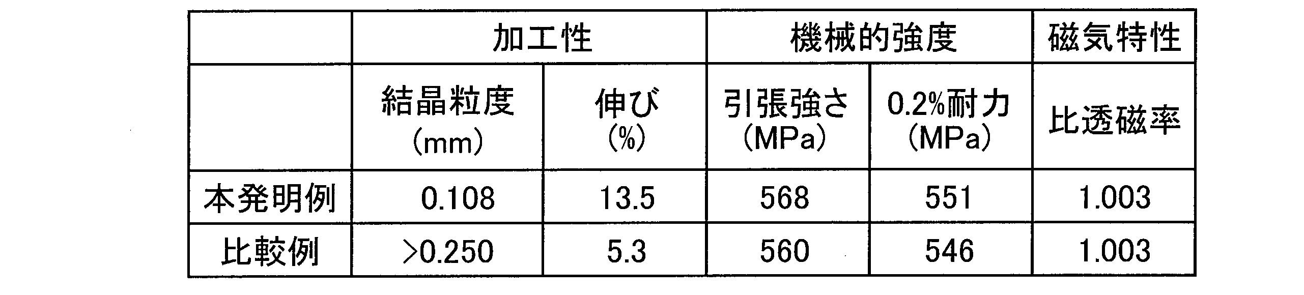
(第3実施例の結果)
加工性としては、Cu層の結晶粒度が0.150mm以下(0.108mm)であった本発明例のクラッド材では、伸びが13.5%になり、10%以上の値になった。つまり、本発明例のクラッド材は、十分な加工性(変形しやすさ)を有しているといえる。一方、Cu層の結晶粒度が0.250mmを超えていた比較例のクラッド材は、伸びが5.3%になり、10%未満の値になった。つまり、比較例のクラッド材は、十分な加工性を有していない虞がある。この結果、Cu層の結晶粒度を0.150mm以下にすることによって、クラッド材に十分な加工性を付与することができるといえる。
加工性としては、Cu層の結晶粒度が0.150mm以下(0.108mm)であった本発明例のクラッド材では、伸びが13.5%になり、10%以上の値になった。つまり、本発明例のクラッド材は、十分な加工性(変形しやすさ)を有しているといえる。一方、Cu層の結晶粒度が0.250mmを超えていた比較例のクラッド材は、伸びが5.3%になり、10%未満の値になった。つまり、比較例のクラッド材は、十分な加工性を有していない虞がある。この結果、Cu層の結晶粒度を0.150mm以下にすることによって、クラッド材に十分な加工性を付与することができるといえる。
また、機械的強度としては、引張強さおよび0.2%耐力のいずれも、本発明例と比較例とでは大きな差が確認されなかった。これにより、本発明例のクラッド材をシャーシなどの構造体に用いることが可能であるといえる。さらに、磁気特性としての比透磁率は、本発明例と比較例とでは大きな差がなく、いずれもほとんど磁化しないことが確認できた。これにより、本発明例のクラッド材を、たとえば、ヒートシンクを兼ねるシャーシに用いる際に、シャーシが磁化することで他部品(たとえば電子部品)に悪影響を与えないようにすることが可能であるといえる。
(変形例)
なお、今回開示された実施形態および実施例は、すべての点で例示であって制限的なものではないと考えられるべきである。本発明の範囲は、上記した実施形態および実施例の説明ではなく特許請求の範囲によって示され、さらに特許請求の範囲と均等の意味および範囲内でのすべての変更が含まれる。
なお、今回開示された実施形態および実施例は、すべての点で例示であって制限的なものではないと考えられるべきである。本発明の範囲は、上記した実施形態および実施例の説明ではなく特許請求の範囲によって示され、さらに特許請求の範囲と均等の意味および範囲内でのすべての変更が含まれる。
たとえば、上記実施形態では、クラッド材30が、ステンレス鋼により構成されるSUS層31(第1層)と、CuまたはCu合金により構成されるCu層32(第2層)と、ステンレス鋼により構成されるSUS層33(第3層)とがこの順に積層された3層構造のクラッド材30から構成されている例を示したが、本発明はこれに限られない。本発明では、ステンレス鋼により構成される第1層と、CuまたはCu合金により構成され、第1層に圧延接合された第2層と、ステンレス鋼により構成され、第2層の第1層とは反対側に圧延接合された第3層とを備えるならば、クラッド材は4層構造以上であってもよい。
また、上記実施形態では、クラッド材30を作製するために、調質圧延、クラッド圧延、中間圧延および仕上げ圧延を行った例を示したが、本発明はこれに限られない。本発明では、クラッド材を作製するために、少なくともクラッド圧延が行われればよく、調質圧延、中間圧延および仕上げ圧延は行われなくてもよい。たとえば、図4において示す中間圧延および仕上げ圧延が行われない工程により作製されたクラッド材は、クラッド圧延後の圧接材(圧接材130)の厚みが最終製品としてのクラッド材(クラッド材30)の厚みとなり、たとえば1.0mm以下、0.5mm以下、0.3mm以下、さらには0.2mm以下などの厚み水準の最終製品としてのクラッド材(クラッド材30)となる。なお、クラッド圧延を容易かつ確実に行うためには、調質圧延を行うのが好ましい。また、クラッド材の厚みの製品毎の差を小さくするためには、中間圧延および仕上げ圧延を行うのが好ましい。
また、上記実施形態では、クラッド材30を携帯機器100のシャーシ3として用いる例を示したが、本発明はこれに限られない。本発明では、クラッド材を携帯機器のシャーシ以外の用途に用いてもよい。たとえば、本発明のクラッド材を電池の導電部材に用いてもよい。なお、本発明のクラッド材は、機械的強度および耐食性のいずれか1つまたは2つと、導電性および熱伝導性のいずれか1つまたは2つとを満たす必要のある用途に好適である。
30 クラッド材
31 SUS層(第1層)
32 Cu層(第2層)
33 SUS層(第3層)
131 SUS板(第1金属板)
132 Cu板(第2金属板)
133 SUS板(第3金属板)
31 SUS層(第1層)
32 Cu層(第2層)
33 SUS層(第3層)
131 SUS板(第1金属板)
132 Cu板(第2金属板)
133 SUS板(第3金属板)
Claims (7)
- ステンレス鋼により構成される第1層(31)と、
CuまたはCu合金により構成され、前記第1層に圧延接合された第2層(32)と、
ステンレス鋼により構成され、前記第2層の前記第1層とは反対側に圧延接合された第3層(33)と、を備え、
全体厚みが1mm以下であり、
積層方向に沿った断面視において、前記第1層の前記積層方向における最小厚みおよび前記第3層の前記積層方向における最小厚みは、それぞれ、前記第1層の前記積層方向における平均厚みおよび前記第3層の前記積層方向における平均厚みの70%以上100%未満である、クラッド材(30)。 - 前記第1層の前記最小厚みの前記クラッド材の厚みに対する百分率の標準偏差、および、前記第3層の前記最小厚みの前記クラッド材の厚みに対する百分率の標準偏差は、1.5%以下である、請求項1に記載のクラッド材。
- 前記第1層および前記第3層は、共にオーステナイト系ステンレス鋼により構成されている、請求項1または2に記載のクラッド材。
- ステンレス鋼により構成された第1金属板(131)と、CuまたはCu合金により構成された第2金属板(132)と、ステンレス鋼により構成された第3金属板(133)と、をこの順で積層させた状態で圧延して接合するクラッド圧延を含み、
4.4×10³N/mm以上の圧接荷重によりクラッド圧延することにより、ステンレス鋼により構成される第1層と、CuまたはCu合金により構成され、前記第1層に圧延接合された第2層と、ステンレス鋼により構成され、前記第2層の前記第1層とは反対側に圧延接合された第3層と、を備え、全体厚みが1mm以下であり、積層方向に沿った断面視において、前記第1層の前記積層方向における最小厚みおよび前記第3層の前記積層方向における最小厚みが、それぞれ、前記第1層の前記積層方向における平均厚みおよび前記第3層の前記積層方向における平均厚みの70%以上100%未満となるクラッド材を作製する、クラッド材(30)の製造方法。 - 前記圧接荷重を4.9×10³N/mm以上とする、請求項4に記載のクラッド材の製造方法。
- 準備する前記第2金属板を、焼鈍処理を行った後に調質圧延されて加工硬化されたものとする、請求項4または5に記載のクラッド材の製造方法。
- 準備する前記第2金属板を、調質圧延後の厚みが調質圧延前の厚みの60%以上100%未満になっているものとする、請求項6に記載のクラッド材の製造方法。
Priority Applications (5)
| Application Number | Priority Date | Filing Date | Title |
|---|---|---|---|
| CN201880048287.1A CN110997211B (zh) | 2017-08-09 | 2018-05-28 | 包层材料和包层材料的制造方法 |
| EP18845236.1A EP3666441B1 (en) | 2017-08-09 | 2018-05-28 | Cladding material and production method of cladding material |
| US16/634,228 US11607867B2 (en) | 2017-08-09 | 2018-05-28 | Clad material |
| KR1020207000405A KR102496226B1 (ko) | 2017-08-09 | 2018-05-28 | 클래드재 및 클래드재의 제조 방법 |
| US17/681,996 US11981107B2 (en) | 2017-08-09 | 2022-02-28 | Method for manufacturing clad material |
Applications Claiming Priority (2)
| Application Number | Priority Date | Filing Date | Title |
|---|---|---|---|
| JP2017-154136 | 2017-08-09 | ||
| JP2017154136A JP6358378B1 (ja) | 2017-08-09 | 2017-08-09 | クラッド材の製造方法 |
Related Child Applications (2)
| Application Number | Title | Priority Date | Filing Date |
|---|---|---|---|
| US16/634,228 A-371-Of-International US11607867B2 (en) | 2017-08-09 | 2018-05-28 | Clad material |
| US17/681,996 Division US11981107B2 (en) | 2017-08-09 | 2022-02-28 | Method for manufacturing clad material |
Publications (1)
| Publication Number | Publication Date |
|---|---|
| WO2019031027A1 true WO2019031027A1 (ja) | 2019-02-14 |
Family
ID=62904845
Family Applications (1)
| Application Number | Title | Priority Date | Filing Date |
|---|---|---|---|
| PCT/JP2018/020405 Ceased WO2019031027A1 (ja) | 2017-08-09 | 2018-05-28 | クラッド材およびクラッド材の製造方法 |
Country Status (6)
| Country | Link |
|---|---|
| US (2) | US11607867B2 (ja) |
| EP (1) | EP3666441B1 (ja) |
| JP (1) | JP6358378B1 (ja) |
| KR (1) | KR102496226B1 (ja) |
| CN (1) | CN110997211B (ja) |
| WO (1) | WO2019031027A1 (ja) |
Cited By (1)
| Publication number | Priority date | Publication date | Assignee | Title |
|---|---|---|---|---|
| WO2019187768A1 (ja) * | 2018-03-29 | 2019-10-03 | 古河電気工業株式会社 | クラッド材及びその製造方法 |
Families Citing this family (2)
| Publication number | Priority date | Publication date | Assignee | Title |
|---|---|---|---|---|
| KR102286363B1 (ko) * | 2019-12-20 | 2021-08-05 | 주식회사 포스코 | 두께 편차가 균일한 클래드 박판의 제조방법 |
| KR102601845B1 (ko) * | 2021-11-09 | 2023-11-15 | 주식회사 디에스피 | 차량용 스피커 그릴 및 그 제조 방법 |
Citations (3)
| Publication number | Priority date | Publication date | Assignee | Title |
|---|---|---|---|---|
| JP2003105500A (ja) * | 2001-09-26 | 2003-04-09 | Nippon Metal Ind Co Ltd | ステンレス鋼/銅クラッドおよびその製造方法 |
| JP2005219478A (ja) | 2004-01-09 | 2005-08-18 | Nippon Steel Corp | クラッド板およびその製造方法 |
| JP5410646B1 (ja) * | 2012-07-10 | 2014-02-05 | 株式会社Neomaxマテリアル | シャーシおよびシャーシの製造方法 |
Family Cites Families (21)
| Publication number | Priority date | Publication date | Assignee | Title |
|---|---|---|---|---|
| JPS5410646B1 (ja) | 1969-05-19 | 1979-05-09 | ||
| US3923558A (en) * | 1974-02-25 | 1975-12-02 | Olin Corp | Copper base alloy |
| US3985589A (en) * | 1974-11-01 | 1976-10-12 | Olin Corporation | Processing copper base alloys |
| DE3506524A1 (de) * | 1985-02-25 | 1986-08-28 | Akzo Gmbh, 5600 Wuppertal | Flexible polyimid-mehrschichtlaminate |
| JPH05161985A (ja) * | 1991-12-13 | 1993-06-29 | Nippon Steel Corp | 複合電磁鋼板の製造方法 |
| US6783870B2 (en) * | 2000-10-16 | 2004-08-31 | Engineered Materials Solutions, Inc. | Self-brazing materials for elevated temperature applications |
| JP2005134073A (ja) | 2003-10-31 | 2005-05-26 | Denso Corp | プレート式熱交換器 |
| JP2008123964A (ja) | 2006-11-15 | 2008-05-29 | Hitachi Cable Ltd | 高強度・高導電性クラッド材及びその製造方法 |
| CN201105358Y (zh) * | 2007-09-07 | 2008-08-27 | 中国联合工程公司 | 一种金属带材的热复合装置 |
| US20100233506A1 (en) * | 2007-09-26 | 2010-09-16 | Furukawa Electric Co., Ltd. | Silver-coated composite material for movable contact and method for manufacturing the same |
| JP5212572B2 (ja) * | 2010-06-02 | 2013-06-19 | 新日鐵住金株式会社 | クラッド材 |
| JP5306418B2 (ja) * | 2010-07-09 | 2013-10-02 | 日新製鋼株式会社 | 銅被覆鋼箔、負極用電極及び電池 |
| CN104145035B (zh) * | 2012-02-24 | 2016-08-24 | 株式会社神户制钢所 | 铜合金 |
| CN202895810U (zh) * | 2012-09-04 | 2013-04-24 | 无锡银荣板业有限公司 | 铜/不锈钢/铜多层复合材料结构 |
| KR20140066413A (ko) * | 2012-11-23 | 2014-06-02 | 한국기계연구원 | 상온 접합력이 향상된 클래드 판재의 제조방법 및 이를 통해 제조된 클래드 판재 |
| CN102974611B (zh) * | 2012-11-28 | 2015-07-08 | 上海实达精密不锈钢有限公司 | 一种柔性太阳能电池基板不锈钢精密钢带成型方法 |
| CN103538313A (zh) * | 2012-12-03 | 2014-01-29 | 黎汉东 | 一种新型热轧钛-铝-不锈钢复合板及其生产方法和用途 |
| JP5965418B2 (ja) | 2014-01-09 | 2016-08-03 | 株式会社日立金属ネオマテリアル | シャーシおよび携帯機器 |
| CN103736729B (zh) * | 2014-01-22 | 2015-07-29 | 太原科技大学 | 一种轧制制备金属复合板带的方法 |
| KR101653742B1 (ko) * | 2015-06-19 | 2016-09-06 | 주식회사 한국클래드텍 | 클래드판의 연속 제조 방법 및 장치 |
| JP6609590B2 (ja) * | 2017-03-30 | 2019-11-20 | Jx金属株式会社 | 層状組織を有する高強度チタン銅条および箔 |
-
2017
- 2017-08-09 JP JP2017154136A patent/JP6358378B1/ja active Active
-
2018
- 2018-05-28 WO PCT/JP2018/020405 patent/WO2019031027A1/ja not_active Ceased
- 2018-05-28 US US16/634,228 patent/US11607867B2/en active Active
- 2018-05-28 EP EP18845236.1A patent/EP3666441B1/en active Active
- 2018-05-28 KR KR1020207000405A patent/KR102496226B1/ko active Active
- 2018-05-28 CN CN201880048287.1A patent/CN110997211B/zh active Active
-
2022
- 2022-02-28 US US17/681,996 patent/US11981107B2/en active Active
Patent Citations (3)
| Publication number | Priority date | Publication date | Assignee | Title |
|---|---|---|---|---|
| JP2003105500A (ja) * | 2001-09-26 | 2003-04-09 | Nippon Metal Ind Co Ltd | ステンレス鋼/銅クラッドおよびその製造方法 |
| JP2005219478A (ja) | 2004-01-09 | 2005-08-18 | Nippon Steel Corp | クラッド板およびその製造方法 |
| JP5410646B1 (ja) * | 2012-07-10 | 2014-02-05 | 株式会社Neomaxマテリアル | シャーシおよびシャーシの製造方法 |
Non-Patent Citations (2)
| Title |
|---|
| "Plate Rolling", 25 October 1960, CORONA PUBLISHING CO., LTD. |
| See also references of EP3666441A4 |
Cited By (2)
| Publication number | Priority date | Publication date | Assignee | Title |
|---|---|---|---|---|
| WO2019187768A1 (ja) * | 2018-03-29 | 2019-10-03 | 古河電気工業株式会社 | クラッド材及びその製造方法 |
| JP6599059B1 (ja) * | 2018-03-29 | 2019-10-30 | 古河電気工業株式会社 | クラッド材及びその製造方法 |
Also Published As
| Publication number | Publication date |
|---|---|
| EP3666441A1 (en) | 2020-06-17 |
| KR20200038925A (ko) | 2020-04-14 |
| CN110997211B (zh) | 2023-01-10 |
| US20210086478A1 (en) | 2021-03-25 |
| JP2019031036A (ja) | 2019-02-28 |
| EP3666441A4 (en) | 2021-04-21 |
| US20220176676A1 (en) | 2022-06-09 |
| JP6358378B1 (ja) | 2018-07-18 |
| US11607867B2 (en) | 2023-03-21 |
| KR102496226B1 (ko) | 2023-02-06 |
| US11981107B2 (en) | 2024-05-14 |
| CN110997211A (zh) | 2020-04-10 |
| EP3666441B1 (en) | 2023-08-09 |
Similar Documents
| Publication | Publication Date | Title |
|---|---|---|
| US11981107B2 (en) | Method for manufacturing clad material | |
| US10953630B2 (en) | Method for manufacturing clad material | |
| US20180281103A1 (en) | Metal laminate material and production method therefor | |
| CN105378119A (zh) | 钢带用钢板及其制造方法以及钢带 | |
| WO2014010455A1 (ja) | シャーシおよびシャーシの製造方法 | |
| CN110690403B (zh) | 电池用引线部件和电池用引线部件的制造方法 | |
| CN108138251A (zh) | 具有区域性不同材料厚度的半成品和结构零件的制造 | |
| CN105814226B (zh) | Cvt用环部件及其制造方法 | |
| US6312834B1 (en) | Clad material and method of manufacturing the material | |
| JP6645490B2 (ja) | クラッド材およびクラッド材の製造方法 | |
| CN115210399A (zh) | 包层钢板及其制造方法以及焊接结构物 | |
| US20210023648A1 (en) | Roll-bonded body and method for producing roll-bonded body | |
| JP4479053B2 (ja) | 高強度かつ平坦性に優れたステンレス鋼板とその製造方法 | |
| JP2019098536A (ja) | クラッド材およびクラッド材の製造方法 | |
| JP2020028884A (ja) | クラッド材の製造方法およびクラッド材 | |
| JP2008123964A (ja) | 高強度・高導電性クラッド材及びその製造方法 | |
| JPH0890257A (ja) | チタン・アルミニウムクラッド箔材の製造方法 | |
| CN119387316B (zh) | 一种沉淀硬化马氏体sus630不锈钢冷轧钢带板形控制方法 | |
| KR101782611B1 (ko) | 클래드 강판 및 그 제조 방법 | |
| JP2017101767A (ja) | 制振鋼板およびその製造方法 | |
| JP2019112718A (ja) | 積層薄板の製造方法及び積層薄板 | |
| JP2017127905A (ja) | エッジ圧延装置、圧延装置及び圧延方法 | |
| Beganović et al. | EFFECT OF UNEVEN PLASTIC DEFORMATION ON WIDTH OF CLAD LAYERS OF EXPLOSIVE WELDED THREE-LAYERS STRIP | |
| JP2011088156A (ja) | 異形断面条材の製造方法 |
Legal Events
| Date | Code | Title | Description |
|---|---|---|---|
| 121 | Ep: the epo has been informed by wipo that ep was designated in this application |
Ref document number: 18845236 Country of ref document: EP Kind code of ref document: A1 |
|
| NENP | Non-entry into the national phase |
Ref country code: DE |
|
| ENP | Entry into the national phase |
Ref document number: 2018845236 Country of ref document: EP Effective date: 20200309 |