WO2019031027A1 - Matériau de gainage et procédé de production de matériau de gainage - Google Patents
Matériau de gainage et procédé de production de matériau de gainage Download PDFInfo
- Publication number
- WO2019031027A1 WO2019031027A1 PCT/JP2018/020405 JP2018020405W WO2019031027A1 WO 2019031027 A1 WO2019031027 A1 WO 2019031027A1 JP 2018020405 W JP2018020405 W JP 2018020405W WO 2019031027 A1 WO2019031027 A1 WO 2019031027A1
- Authority
- WO
- WIPO (PCT)
- Prior art keywords
- layer
- thickness
- sus
- rolling
- clad
- Prior art date
- Legal status (The legal status is an assumption and is not a legal conclusion. Google has not performed a legal analysis and makes no representation as to the accuracy of the status listed.)
- Ceased
Links
Images





Classifications
-
- B—PERFORMING OPERATIONS; TRANSPORTING
- B32—LAYERED PRODUCTS
- B32B—LAYERED PRODUCTS, i.e. PRODUCTS BUILT-UP OF STRATA OF FLAT OR NON-FLAT, e.g. CELLULAR OR HONEYCOMB, FORM
- B32B15/00—Layered products comprising a layer of metal
- B32B15/01—Layered products comprising a layer of metal all layers being exclusively metallic
- B32B15/013—Layered products comprising a layer of metal all layers being exclusively metallic one layer being formed of an iron alloy or steel, another layer being formed of a metal other than iron or aluminium
- B32B15/015—Layered products comprising a layer of metal all layers being exclusively metallic one layer being formed of an iron alloy or steel, another layer being formed of a metal other than iron or aluminium the said other metal being copper or nickel or an alloy thereof
-
- B—PERFORMING OPERATIONS; TRANSPORTING
- B21—MECHANICAL METAL-WORKING WITHOUT ESSENTIALLY REMOVING MATERIAL; PUNCHING METAL
- B21B—ROLLING OF METAL
- B21B1/00—Metal-rolling methods or mills for making semi-finished products of solid or profiled cross-section; Sequence of operations in milling trains; Layout of rolling-mill plant, e.g. grouping of stands; Succession of passes or of sectional pass alternations
- B21B1/22—Metal-rolling methods or mills for making semi-finished products of solid or profiled cross-section; Sequence of operations in milling trains; Layout of rolling-mill plant, e.g. grouping of stands; Succession of passes or of sectional pass alternations for rolling plates, strips, bands or sheets of indefinite length
-
- B—PERFORMING OPERATIONS; TRANSPORTING
- B23—MACHINE TOOLS; METAL-WORKING NOT OTHERWISE PROVIDED FOR
- B23K—SOLDERING OR UNSOLDERING; WELDING; CLADDING OR PLATING BY SOLDERING OR WELDING; CUTTING BY APPLYING HEAT LOCALLY, e.g. FLAME CUTTING; WORKING BY LASER BEAM
- B23K20/00—Non-electric welding by applying impact or other pressure, with or without the application of heat, e.g. cladding or plating
- B23K20/04—Non-electric welding by applying impact or other pressure, with or without the application of heat, e.g. cladding or plating by means of a rolling mill
-
- B—PERFORMING OPERATIONS; TRANSPORTING
- B32—LAYERED PRODUCTS
- B32B—LAYERED PRODUCTS, i.e. PRODUCTS BUILT-UP OF STRATA OF FLAT OR NON-FLAT, e.g. CELLULAR OR HONEYCOMB, FORM
- B32B15/00—Layered products comprising a layer of metal
- B32B15/01—Layered products comprising a layer of metal all layers being exclusively metallic
-
- C—CHEMISTRY; METALLURGY
- C21—METALLURGY OF IRON
- C21D—MODIFYING THE PHYSICAL STRUCTURE OF FERROUS METALS; GENERAL DEVICES FOR HEAT TREATMENT OF FERROUS OR NON-FERROUS METALS OR ALLOYS; MAKING METAL MALLEABLE, e.g. BY DECARBURISATION OR TEMPERING
- C21D1/00—General methods or devices for heat treatment, e.g. annealing, hardening, quenching or tempering
- C21D1/26—Methods of annealing
-
- C—CHEMISTRY; METALLURGY
- C22—METALLURGY; FERROUS OR NON-FERROUS ALLOYS; TREATMENT OF ALLOYS OR NON-FERROUS METALS
- C22C—ALLOYS
- C22C38/00—Ferrous alloys, e.g. steel alloys
- C22C38/18—Ferrous alloys, e.g. steel alloys containing chromium
- C22C38/40—Ferrous alloys, e.g. steel alloys containing chromium with nickel
-
- C—CHEMISTRY; METALLURGY
- C22—METALLURGY; FERROUS OR NON-FERROUS ALLOYS; TREATMENT OF ALLOYS OR NON-FERROUS METALS
- C22C—ALLOYS
- C22C9/00—Alloys based on copper
-
- B—PERFORMING OPERATIONS; TRANSPORTING
- B23—MACHINE TOOLS; METAL-WORKING NOT OTHERWISE PROVIDED FOR
- B23K—SOLDERING OR UNSOLDERING; WELDING; CLADDING OR PLATING BY SOLDERING OR WELDING; CUTTING BY APPLYING HEAT LOCALLY, e.g. FLAME CUTTING; WORKING BY LASER BEAM
- B23K2103/00—Materials to be soldered, welded or cut
- B23K2103/02—Iron or ferrous alloys
- B23K2103/04—Steel or steel alloys
- B23K2103/05—Stainless steel
-
- B—PERFORMING OPERATIONS; TRANSPORTING
- B23—MACHINE TOOLS; METAL-WORKING NOT OTHERWISE PROVIDED FOR
- B23K—SOLDERING OR UNSOLDERING; WELDING; CLADDING OR PLATING BY SOLDERING OR WELDING; CUTTING BY APPLYING HEAT LOCALLY, e.g. FLAME CUTTING; WORKING BY LASER BEAM
- B23K2103/00—Materials to be soldered, welded or cut
- B23K2103/08—Non-ferrous metals or alloys
- B23K2103/12—Copper or alloys thereof
-
- B—PERFORMING OPERATIONS; TRANSPORTING
- B23—MACHINE TOOLS; METAL-WORKING NOT OTHERWISE PROVIDED FOR
- B23K—SOLDERING OR UNSOLDERING; WELDING; CLADDING OR PLATING BY SOLDERING OR WELDING; CUTTING BY APPLYING HEAT LOCALLY, e.g. FLAME CUTTING; WORKING BY LASER BEAM
- B23K2103/00—Materials to be soldered, welded or cut
- B23K2103/18—Dissimilar materials
- B23K2103/22—Ferrous alloys and copper or alloys thereof
-
- C—CHEMISTRY; METALLURGY
- C21—METALLURGY OF IRON
- C21D—MODIFYING THE PHYSICAL STRUCTURE OF FERROUS METALS; GENERAL DEVICES FOR HEAT TREATMENT OF FERROUS OR NON-FERROUS METALS OR ALLOYS; MAKING METAL MALLEABLE, e.g. BY DECARBURISATION OR TEMPERING
- C21D2211/00—Microstructure comprising significant phases
- C21D2211/001—Austenite
-
- C—CHEMISTRY; METALLURGY
- C21—METALLURGY OF IRON
- C21D—MODIFYING THE PHYSICAL STRUCTURE OF FERROUS METALS; GENERAL DEVICES FOR HEAT TREATMENT OF FERROUS OR NON-FERROUS METALS OR ALLOYS; MAKING METAL MALLEABLE, e.g. BY DECARBURISATION OR TEMPERING
- C21D2251/00—Treating composite or clad material
- C21D2251/02—Clad material
-
- H—ELECTRICITY
- H05—ELECTRIC TECHNIQUES NOT OTHERWISE PROVIDED FOR
- H05K—PRINTED CIRCUITS; CASINGS OR CONSTRUCTIONAL DETAILS OF ELECTRIC APPARATUS; MANUFACTURE OF ASSEMBLAGES OF ELECTRICAL COMPONENTS
- H05K5/00—Casings, cabinets or drawers for electric apparatus
- H05K5/04—Metal casings
Definitions
- the present invention relates to a clad material and a method of manufacturing the clad material.
- a clad material is formed by rolling and joining first and third layers made of stainless steel and a second layer made of Cu or a Cu alloy disposed between the first and third layers.
- first and third layers made of stainless steel
- second layer made of Cu or a Cu alloy disposed between the first and third layers.
- a cover layer (first layer, third layer) made of stainless steel is rolled and bonded on both sides of a central layer (second layer) made of copper or copper alloy.
- the cover layer is bonded to the central layer through a barrier layer made of Nb or the like.
- the clad plate is rolled and joined by thickness reduction processing such as hot rolling and warm cold rolling.
- the clad material disclosed in Japanese Patent Application Laid-Open No. 2005-219478 has a place where the thickness is excessively small in the first layer or the third layer formed of stainless steel. It has been discovered that in some cases, as a result, welding strength may be reduced when welding the clad material to another member, and that mechanical strength variation of the clad material may occur.
- the present invention has been made to solve the problems as described above, and one object of the present invention is to reduce the welding strength when welding a clad material to another member, and a clad material It is an object of the present invention to provide a clad material and a method of manufacturing the clad material, which can suppress the occurrence of the mechanical strength variation.
- the inventor of the present application has found that the minimum thickness in the stacking direction of the first layer and the minimum thickness in the stacking direction of the third layer are excessive with respect to the target thickness (target value). It has further been found that, due to the small size, the welding strength may be reduced when welding the clad material to other members, and that the mechanical strength of the clad material may vary. The present invention has been completed based on such findings.
- the clad material according to the first aspect of the present invention comprises the first layer made of stainless steel, the second layer made of Cu or Cu alloy, and the second layer rolled and joined to the first layer, and stainless steel And the third layer rolled and joined to the side opposite to the first layer of the second layer, and the total thickness is 1 mm or less, and in a cross-sectional view along the stacking direction, the first layer in the stacking direction
- the minimum thickness and the minimum thickness in the stacking direction of the third layer are 70% or more and less than 100% of the average thickness in the stacking direction of the first layer and the average thickness in the stacking direction of the third layer, respectively.
- Stainless steel means an alloy containing 50 mass% or more of Fe (iron) as a main component and further containing at least 10.5 mass% of Cr (chromium).
- Cu alloy means an alloy containing Cu (copper) as a main component at 50% by mass or more.
- the “minimum thickness of the first layer in the stacking direction” and the “minimum thickness of the third layer in the stacking direction” have predetermined lengths along the rolling direction of the clad material in the cross-sectional view along the stacking direction. This means the minimum of the thickness of the first layer and the minimum of the thickness of the third layer in the thickness range.
- the minimum thickness in the stacking direction of the first layer and the minimum thickness in the stacking direction of the third layer are each It is 70% or more and less than 100% of the average thickness in the stacking direction of one layer and the average thickness in the stacking direction of the third layer.
- the thickness in the stacking direction of the first layer and the third layer is equalized, so that the location where the thickness is excessively small in the first layer and the third layer (less than 70% of the average thickness) Can be suppressed.
- the effect of this configuration is particularly effective when the overall thickness is as small as 1 mm or less and the average thickness of the first and third layers is small (for example, 0.20 mm or less).
- the first layer and the third layer may be broken or pinholes, and the second layer is not coated. It can control that a place arises.
- the clad material according to the first aspect is, as described above, a first layer made of stainless steel, a second layer made of Cu or a Cu alloy, and rolled and joined to the first layer, stainless steel And a third layer rolled and joined to the side opposite to the first layer of the second layer.
- the second layer composed of Cu or a Cu alloy while maintaining mechanical strength and corrosion resistance with the first layer and third layer composed of stainless steel, and conductivity and heat Conductivity can be secured.
- the standard deviation of the percentage of the minimum thickness of the first layer with respect to the thickness of the clad material and the standard deviation of the percentage of the minimum thickness of the third layer with respect to the thickness of the clad material are It is 1.5% or less.
- the first layer and the third layer are both made of austenitic stainless steel.
- the austenitic stainless steel and Cu or Cu alloy are nonmagnetic, the entire clad material can be made nonmagnetic.
- a method of manufacturing a clad material comprising: a first metal plate made of stainless steel; a second metal plate made of Cu or a Cu alloy; and a third metal made of stainless steel
- a clad rolling including rolling and joining in a state in which the plate and the steel are stacked in this order, and the clad rolling with a pressure contact load of 4.4 ⁇ 10 3 N / mm or more makes the first member made of stainless steel Layer, a second layer formed of Cu or Cu alloy and roll bonded to the first layer, and a third layer formed of stainless steel and roll bonded to the opposite side of the first layer of the second layer
- the minimum thickness of the first layer in the stacking direction and the minimum thickness of the third layer in the stacking direction are each in the stacking direction of the first layer.
- the “pressure contact load” in the present invention is the combined force of forces acting on the rolling roller from the rolled material (in the present invention, the first metal plate, the second metal plate and the third metal plate) during clad rolling. And the force per unit length.
- This pressure contact load may also be referred to as rolling load or pressure reduction.
- the first metal plate made of stainless steel, the second metal plate made of Cu or Cu alloy, and stainless steel are used. Clad rolling is performed with a pressure contact load of 4.4 ⁇ 10 3 N / mm or more in a state in which the third metal plate thus stacked is laminated in this order. Thus, clad rolling is performed with a sufficient pressure contact load of 4.4 ⁇ 10 3 N / mm or more, and therefore, the first and third metal plates made of stainless steel and Cu or a Cu alloy are used. It is possible to suppress rolling such that each layer is plastically deformed nonuniformly due to the difference in ductility with the second metal sheet.
- the clad material it is possible to prevent the thickness in the stacking direction of the first layer and the thickness in the stacking direction of the third layer from becoming uneven, so the first layer or the third layer made of stainless steel It is possible to suppress the occurrence of an excessively small thickness in the three layers.
- the first layer and the third layer may be broken or pinholes, and the second layer is not coated. Can be suppressed.
- the pressing load is set to 4.9 ⁇ 10 3 N / mm or more.
- the clad rolling can be performed with a more sufficient pressure contact load, and therefore, it is possible to further suppress rolling so that each layer is plastically deformed nonuniformly.
- the second metal plate to be prepared is temper-rolled and work-hardened after being subjected to annealing treatment.
- a second metal plate made of Cu or a Cu alloy a second metal plate in which internal stress (strain) is accumulated and mechanical strength (0.2% proof stress or the like) is improved It can be used.
- the mechanical strength of the second metal plate which is lower in mechanical strength compared to the first metal plate and the third metal plate made of stainless steel, is used as the mechanical strength of the first metal plate and the third metal plate. It can be approached.
- each layer is rolled so as to plastically deform more uniformly. Therefore, the first metal plate, the second metal plate, and the third metal While being able to fully join with a board, the thickness of each layer can be formed with high precision.
- the second metal plate to be prepared has a thickness after temper rolling of at least 60% and less than 100% of the thickness before temper rolling.
- the internal stress (the second metal plate to be prepared) is obtained due to the thickness after temper rolling being less than 60% of the thickness before temper rolling. Excessive accumulation of distortion can be suppressed.
- the crystal of the second layer (the second metal plate) can be prevented from becoming coarse due to a large internal stress (strain), so the elongation of the cladding material (processing) can be attributed to the second layer. Can be suppressed.
- the present invention it is possible to suppress the decrease in welding strength when welding a clad material to another member, and the clad that can suppress the occurrence of variations in mechanical strength of the clad material. It is possible to provide a material and a method of manufacturing the clad material.
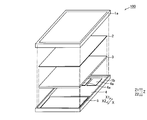
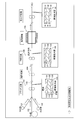
- FIG. 1 is a cross-sectional view showing a structure of a clad material (chassis) according to an embodiment of the present invention. It is a schematic diagram for demonstrating the manufacturing process of the clad material by one Embodiment of this invention. It is a schematic diagram for demonstrating the manufacturing process of the clad material by one Embodiment of this invention. It is the front view which showed the rolling roller for producing the clad material by one Embodiment of this invention.
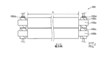
- FIG. 5 is an enlarged side view showing a rolling roller for producing a clad material according to an embodiment of the present invention.
- the portable device 100 includes an upper housing 1a, a display 2, a chassis 3, a substrate 4, a battery 5, and a lower housing 1b.
- the display 2, the chassis 3, the substrate 4, and the battery 5 are disposed in the lower housing 1 b in this order from the upper side (Z 1 side).
- the lower housing 1b is covered by the upper housing 1a from above.
- the display 2 includes a liquid crystal display, an organic EL display, and the like, and has a function of displaying an image on the upper surface on the Z1 side.
- the chassis 3 has a function of securing the mechanical strength of the portable device 100 and a function of emitting heat from the display 2, the substrate 4 (electronic component 4 a) and the battery 5 to the outside. That is, the chassis 3 doubles as a heat sink. Further, a member (not shown) of the portable device 100 is welded to the chassis 3.
- the substrate 4 is disposed on the X1 side of the lower housing 1b, and the battery 5 is disposed on the X2 side.
- an electronic component 4a such as a CPU (Central Processing Unit) for driving an application is disposed.
- a SUS layer 31 made of stainless steel, a Cu layer 32 made of Cu or a Cu alloy, and a SUS layer 33 made of stainless steel are stacked in this order. It is comprised from the clad material 30 of 3 layer structure.
- the Cu layer 32 is rolled and joined to the Z1 side surface (upper surface) of the SUS layer 33 and is rolled and joined to the Z2 side surface (lower surface) of the SUS layer 31.
- the respective layers form an interatomic bond by diffusion annealing to strongly bond each other.
- SUS layer 31 and the SUS layer 33 are examples of the “first layer”, the “second layer”, and the “third layer” in the claims respectively.
- the thickness t1 of the cladding material 30 in the Z direction is not particularly limited.
- the thickness t1 of the chassis 3 is preferably 1 mm or less, and more preferably 0 in order to suppress an increase in the thickness in the Z direction in consideration of the weight reduction and the size reduction of the portable device 100. .5 mm or less.
- the thickness t1 of the chassis 3 is preferably 0.03 mm or more, more preferably 0.05 mm or more, and further preferably Is preferably 0.1 mm or more.
- the thickness of the Cu layer 32 be larger than that of the SUS layers (31, 33) from the viewpoint of heat dissipation.
- the thickness of the Cu layer 32 is too large, the thickness of the SUS layer (31, 33) becomes small, and when it is rolled and joined to the Cu layer 32, there is a possibility that a tear or a pinhole may occur. As a result, there is a possibility that a place where the Cu layer 32 is not covered with the SUS layer (31, 33) may occur. Therefore, when the thickness of the SUS layer is 1, the layer thickness ratio (SUS layer: Cu layer: SUS layer) is 2 to 8 (1: 2: 1 to 1: 8: 1). Preferably there.
- the stainless steel constituting the SUS layer 31 and the SUS layer 33 is not particularly limited as long as it is stainless steel, such as austenite, ferrite and martensite.
- the chassis 3 it is not preferable that the chassis 3 be magnetic in the portable device 100 including the electronic component 4a (see FIG. 1). Therefore, the stainless steel forming the SUS layer 31 and the SUS layer 33 is preferably an austenitic stainless steel, and more preferably a so-called SUS300-based (JIS standard) austenitic stainless steel.
- the stainless steel constituting the SUS layer 31 and the SUS layer 33 be SUS316L (JIS standard) which has a small content of C (carbon) and is less likely to be magnetic.
- SUS316 JIS standard
- SUS316 JIS standard
- the SUS layer 31 and the SUS layer 33 are not limited to the same composition, it is preferable to be made of stainless steel having the same composition in consideration of rolling stability and the like.
- the Cu layer 32 is made of Cu of C1000 series (JIS standard) or Cu alloy such as C2000 series (JIS standard). Examples of Cu include so-called oxygen free copper, phosphorus-deoxidized copper, tough pitch copper and the like. Further, as the Cu alloy, a Zr-Cu alloy of C1050 (JIS standard) or the like is preferable in order to suppress crystal coarsening. Generally, Cu or a Cu alloy constituting the Cu layer 32 has higher thermal conductivity and larger ductility than stainless steels constituting the SUS layer 31 and the SUS layer 33.
- the grain size of the Cu layer 32 (Cu or Cu alloy) measured by the comparative method of JIS H 0501 is preferably 0.150 mm or less, and the elongation (ductility) of the Cu layer 32 is prevented from being reduced. can do.
- the thicknesses t2 and t3 of the SUS layers 31 and 33 vary in the rolling direction, respectively.
- minimum thicknesses t2 min and t3 min smaller than the thicknesses t2 and t3 of the other portions exist, respectively.
- the interface of the cladding material 30 becomes wavy in a cross-sectional view along the stacking direction (Z direction).
- the wave form of the interface is shown exaggeratingly.
- the minimum thickness t2min in the stacking direction of the SUS layer 31 and the minimum thickness t3min in the stacking direction of the SUS layer 33 are respectively
- the average thickness t2avg in the stacking direction of the SUS layer 31 and the average thickness t3avg in the stacking direction of the SUS layer 33 are 70% or more and less than 100%.
- the minimum thickness t2min in the stacking direction of the SUS layer 31 is the minimum thickness t2 of the SUS layer 31 in a predetermined range (length) in the rolling direction of the clad material 30.
- the minimum thickness t3min in the stacking direction of the SUS layer 33 is the minimum thickness t3 of the SUS layer 33 in a predetermined range (length) in the rolling direction of the clad material 30.
- the above-mentioned predetermined range (length) in the clad material 30 is not particularly limited as long as it is a range of one or more wavelengths of the wave of the interface formed in a wave shape, but from the viewpoint of measurement reliability It is good.
- the average thickness t2avg of the SUS layer 31 in the stacking direction is the average of the thickness t2 of the SUS layer 31 in the clad material 30.
- the average thickness t3avg of the SUS layer 33 in the stacking direction is the average of the thickness t3 of the SUS layer 33 in the clad material 30.
- the average thicknesses t2avg and t3avg respectively measure the thicknesses t2 and t3 at a plurality of locations (e.g., 10 or more locations) of the SUS layers 31 and 33 at random, for example, in the predetermined range (length) of the cladding material 30 described above.
- the thickness t4 of the Cu layer 32 is the same as the average thicknesses t2avg and t3avg of the SUS layers 31 and 33 described above as the average thickness t4avg (hereinafter, simply referred to as "t4" because of little variation). It is good to ask by
- the standard deviation (%) of the percentage of the minimum thickness t2min of the SUS layer 31 to the thickness t1 of the clad material 30 and the standard deviation (%) of the percentage of the minimum thickness t3min of the SUS layer 33 to the thickness t1 of the clad material 30 are The both are preferably 1.5% or less, more preferably 1.2% or less.
- the thickness ratio (t2avg / t1) of the composition (material) of the stainless steel constituting each layer and the average thickness (t2avg, t3avg) to the thickness (t1) of the cladding material 30 When t3avg / t1) is equal to each other, it is considered that the variations in the minimum thickness and the minimum thickness in the SUS layer 31 and the SUS layer 33 become equal. Therefore, in this case, the data of the SUS layer 31 and the SUS layer 33 can be added together and evaluated to be treated as the minimum thickness and standard deviation of the pair of SUS layers.
- the ratio (t2avg: t4: t3avg) of the average thickness t2avg of the SUS layer 31 and the thickness t4 of the Cu layer 32 and the average thickness t3avg of the SUS layer 33 in the clad material 30 is not particularly limited. It is preferable that the average thickness t2avg of the SUS layer 31 and the average thickness t3avg of the SUS layer 33 both be substantially equal in order to equalize the degree of extension in cladding rolling etc. on both sides in the Z direction. .
- the thickness ratio different according to the characteristics (heat conductivity and mechanical strength) required in the chassis 3.
- the thickness t4 of the Cu layer 32 is preferably 60% or less of the thickness t1 of the cladding material 30.
- thermal conductivity is particularly required in the chassis 3, it is preferable to increase the thickness t4 of the Cu layer 32.
- the thickness t 4 of the Cu layer 32 is preferably 33% or more of the thickness t 1 of the clad material 30.
- the elongation of the clad material 30 is preferably 8% or more, and more preferably 10% or more, from the viewpoint of press workability and the like.
- a strip-like Cu plate 132 made of Cu or a Cu alloy is prepared. Then, softening annealing is performed on the Cu plate 132 using the annealing furnace 101 whose inside is set to a temperature exceeding the recrystallization temperature (for example, 220 ° C.) of the Cu or Cu alloy constituting the Cu plate 132. As a result, the internal distortion of the Cu plate 132 due to work hardening is removed, and the structure is sufficiently softened.
- the recrystallization temperature for example, 220 ° C.
- temper rolling is performed using the rolling roller 102 on the Cu plate 132 which has been subjected to the softening and annealing.
- the Cu plate 132 accumulates internal stress (strain) and is work-hardened.
- the pass number of temper rolling can be selected suitably.
- temper rolling is preferably performed so that the thickness t14 of the Cu plate 132 after temper rolling is 60% or more and less than 100% of the thickness t14 of the Cu plate 132 before temper rolling.
- crystallization of the Cu layer 32 of the clad material 30 is easily performed by making thickness t14 in Cu board 132 after temper rolling 60% or more of thickness t14 in Cu board 132 before temper rolling. It is possible to suppress. As a result, the Cu plate 132 to be prepared can be temper-rolled and work-hardened after annealing treatment.
- a strip-like SUS plate 131 and a strip-like SUS plate 133 made of stainless steel are prepared. Further, both SUS plates 131 and 133 are sufficiently annealed.
- the thickness ratio of the SUS plate 131, the thickness of the Cu plate 132 that has undergone temper rolling, and the thickness of the SUS plate 133 are the thickness ratio of the SUS layer 31 to the Cu layer 32 and the SUS layer 33 in the clad material 30 to be produced. It is suitably selected according to (t2avg: t4: t3avg).
- a pressure contact material 130 having a thickness of, for example, 1.0 mm or less or 0.5 mm or less in which the SUS plate 131, the Cu plate 132, and the SUS plate 133 are bonded (rolled) to one another Is made.
- the number of passes of clad rolling can be selected suitably.
- the rolling roller 103 includes a pair of work rollers 103a and 103b, four bearings 103c for holding the axes of the work rollers 103a and 103b, and a bearing 103c of the work roller 103a on the Z1 side, for example. And a pair of load cells 103d to be attached.
- the pair of load cells 103 d detects the strain caused by the force (combined force) acting on the work roller 103 a, thereby acting on the work roller 103 a from the SUS plate 131, the Cu plate 132 and the SUS plate 133 (rolling material) Combined force) has a function of detecting P0 (N).
- the thickness of the pressure-contacting material at the outlet side of the rolling roller can be calculated from the values of pressure-contacting load, plate width, rolling force function, deformation resistance and the like. Therefore, by determining the pressure contact load, it is possible to set various conditions for achieving a desired plate thickness in accordance with the rolling mill to be used. Further, the plate thickness is equal to the sum of the deformation of the rolling mill due to the pressure contact load and the roll setting position of the rolling mill. Therefore, adjustment can be made by changing the roll setting position in order to obtain a desired plate thickness.
- a rational rolling plan relates to a pressure contact load. Since the pressure contact load can be calculated from various conditions such as the thickness before rolling and the roll radius, by setting the pressure contact load in advance, a reasonable rolling plan can be made without specifying other conditions. Becomes possible.
- the pressure contact load P in clad rolling is set to be 4.4 ⁇ 10 3 N / mm or more.
- the pressing load P is L (mm) when the length of the roller surface in the axial direction of the work roller 103a (103b) (also referred to as the “width direction” in the direction perpendicular to the rolling direction and the stacking direction).
- the force P0 applied to the work roller 103a can be obtained from the following equation (1).
- P P0 / L (1)
- the pressure contact load P (N / mm) can be obtained as an estimate from the following equation (2).
- P Qp ⁇ k ⁇ ((R ⁇ (h1-h2)) / L (2)
- the rolling force function (the magnification compared to the ideal deformation) is Qp
- the average deformation resistance (in the two-dimensional deformation state when the deformation in the width direction is ignored)
- the average stress required to achieve is k (N / mm 2 ).
- the radius of work roller 103a (103b) is R (mm)
- the total thickness of SUS plate 131, Cu plate 132 and SUS plate 133 (rolling material) on the inlet side of rolling roller 103 is h1 (mm)
- the thickness of the pressure-contacting material 130 at the outlet side of the rolling roller 103 is h2 (mm).
- the pressure contact load P can be increased by appropriately combining the force (tension) along the rolling direction applied to the rolled material, reducing the conveying speed of the rolled material, and the like.
- the pressure load P is 4.9. preferably at ⁇ 10 3 N / mm or more, more preferably 6.0 ⁇ 10 3 N / mm or more, more preferably at 6.8 ⁇ 10 3 N / mm or more.
- the pressure load P when performing clad rolling continuously, since the tact time of clad material 30 will increase if pressure welding speed is small, it is not desirable. For this reason, when priority is given to shortening the tact time, it is preferable to set the pressure load P to 4.4 ⁇ 10 3 N / mm or more and to a value near 4.4 ⁇ 10 3 N / mm.
- the pressure contact load P in clad rolling is set to be 4.4 ⁇ 10 3 N / mm or more.
- the minimum thickness t2min of the SUS layer 31 and the minimum thickness t3min of the SUS layer 33 in the clad material 30 as the final product can be 70% or more and less than 100% of the average thickness t2avg and the average thickness t3avg, respectively. .
- the average thicknesses t12avg and t13avg of the SUS plates 131 and 133 may be determined from a predetermined range (length) in the rolling direction of the clad material.
- the predetermined range (length) is not particularly limited as long as it is a range of one or more wavelengths of the wave of the interface formed in a wave shape, but it is preferable that it is at least about 15 mm from the viewpoint of measurement reliability.
- the average thickness t12avg of the SUS plate 131 is the average of the thickness t12 of the SUS plate 131 in the pressure contact material 130
- the average thickness t13avg of the SUS plate 133 is the average of the thickness t13 of the SUS plate 133 in the pressure contact material 130.
- the widthwise length of the pressure welding material 130 may be adjusted by cutting the widthwise end of the pressure welding material 130 using the end cutting machine 104 as necessary. Then, the thickness of the pressure contact material 130 is adjusted by performing intermediate rolling on the pressure contact material 130 using a rolling roller 105. As a result, it is possible to reduce the variation in thickness of the pressure-contacting material 130 (cladding material 30). Further, the number of intermediate rolling passes can be selected as appropriate.
- diffusion annealing is performed using an annealing furnace 106 whose inside is set to a temperature exceeding the recrystallization temperature of the stainless steel forming the SUS plate 131.
- the structure of each of the SUS plate 131, the Cu plate 132 and the SUS plate 131 is softened according to the material.
- the layers form an interatomic bond by diffusion processing and are strongly bonded.
- the manufacturing method of this invention is not limited to the structure which performs continuously the process from slit cutting of a clad rolling to a finishing process.
- the average thickness t2avg of the SUS layer 31 of the clad material 30 described above is the total of the prepared SUS plate 131, Cu plate 132 and SUS plate 133 in the thickness t1 of the clad material 30 (see FIG. 2).
- the average thicknesses t12avg and t13avg may be determined by measuring the thicknesses t2, t3, t12, and t13 at a plurality of locations (for example, 10 or more locations) of the corresponding layer and plate, and calculating the average thereof.
- the thickness t14 (see FIG. 4) of the Cu plate 132 before diffusion annealing (after intermediate rolling) is the thickness t14 (FIG. 4) of the Cu plate 132 after softening annealing (before temper rolling). It is preferable to make it 20% or more of 3).
- the grain size of the Cu or Cu alloy in the Cu layer 32 (Cu plate 132 after diffusion annealing) can be reduced to 150 ⁇ m or less.
- the processability can be improved.
- the minimum thickness t2min in the stacking direction of the SUS layer 31 and the minimum thickness t3min in the stacking direction of the SUS layer 33 are respectively SUS layers.
- the average thickness t2avg in the stacking direction 31 and the average thickness t3avg in the stacking direction of the SUS layer 33 are 70% or more and less than 100%.
- the thicknesses t2 and t3 in the stacking direction of the SUS layer 31 and the SUS layer 33 are equalized respectively, so that the SUS layer 31 and the SUS layer 33 have excessively small thicknesses (70 It is possible to suppress the occurrence of less than%).
- the other member when welding the chassis 3 formed of the clad material 30 to another member, the other member is welded to a place where the thickness t2 of the SUS layer 31 or the thickness t3 of the SUS layer 33 is excessively small. Since it can suppress, it can suppress that welding strength falls without performing sufficient welding. Moreover, it can suppress that the dispersion
- the clad material 30 is made of a SUS layer 31 made of stainless steel, Cu or a Cu alloy, and a Cu layer 32 which is rolled and joined to the SUS layer 31, and stainless steel. And a SUS layer 33 rolled and joined to the opposite side of the Cu layer 32 to the SUS layer 31.
- the standard deviation of the percentage of the minimum thickness t2 min of the SUS layer 31 to the thickness t1 of the cladding material 30 and the standard of the percentage of the minimum thickness t3 min of the SUS layer 33 to the thickness t1 of the cladding material 30 Deviation is 1.5% or less.
- both the SUS layer 31 and the SUS layer 33 are made of austenitic stainless steel. According to this structure, since both the austenitic stainless steel and Cu or Cu alloy are nonmagnetic, the entire clad material 30 can be made nonmagnetic. Thereby, it is possible to prevent the electronic components 4 a and the like from being adversely affected by the magnetization of the chassis 3 which also serves as the heat sink made of the clad material 30.
- the thickness t2 in the stacking direction of the SUS layer 31 and the thickness t3 in the stacking direction of the SUS layer 33 can be both suppressed from becoming nonuniform. Therefore, along the stacking direction (Z direction) In the cross-sectional view, the minimum thickness t2min in the stacking direction of the SUS layer 31 and the minimum thickness t3min in the stacking direction of the SUS layer 33 are the average thickness t2avg in the stacking direction of the SUS layer 31 and the average thickness in the stacking direction of the SUS layer 33, respectively. It can be 70% or more and less than 100% of avg. Therefore, it is possible to suppress the occurrence of a place where the thickness is excessively small in the SUS layer 31 or the SUS layer 33 made of stainless steel.
- the pressing load P is set to 4.9 ⁇ 10 3 N / mm or more.
- the clad rolling can be performed with a more sufficient pressure contact load P, and therefore, it is possible to further suppress rolling such that each layer is plastically deformed nonuniformly.
- the Cu plate 132 to be prepared is temper-rolled and work-hardened after annealing treatment.
- the Cu plate 132 made of Cu or a Cu alloy it is possible to use a Cu plate 132 in which internal stress (strain) is accumulated and mechanical strength (0.2% proof stress or the like) is improved.
- the mechanical strength of the Cu plate 132 whose mechanical strength is lower than that of the SUS plate 131 and the SUS plate 133 made of stainless steel can be brought close to the mechanical strength of the SUS plate 131 and the SUS plate 133. Therefore, clad rolling can be performed by metal plates having similar mechanical strength, so that each layer is rolled so as to plastically deform more uniformly. Therefore, SUS plate 131, Cu plate 132 and SUS plate 133 are sufficiently And the thickness of each layer can be formed with high precision.
- the Cu plate 132 to be prepared has a thickness after temper rolling of at least 60% and less than 100% of the thickness before temper rolling.
- the internal stress (strain) in the Cu plate 132 to be prepared due to the thickness after temper rolling being less than 60% of the thickness before temper rolling Can be suppressed from being accumulated excessively.
- each press contact material having a pair of SUS plate (first metal plate) and SUS plate (third metal plate) immediately after clad rolling when clad rolling is performed with different press load P being different.
- the thickness (minimum thickness t ⁇ min) of the thinnest portion (thinnest portion) of the SUS plate and the average value (average thickness t ⁇ avg) of the thickness of the SUS plate were obtained.
- the pressure welding material was prepared by the manufacturing method shown in FIGS. 3 and 4.
- a Cu plate 132 (second metal plate) made of oxygen free copper (C1020, JIS standard) and having a thickness t14 of 0.5 mm was prepared.
- This Cu plate was in the shape of a long band in the rolling direction.
- the Cu plate 132 was softened and annealed at a temperature exceeding the recrystallization temperature of Cu constituting the Cu plate 132, and then temper rolling was performed.
- thickness t14 in Cu board 132 after temper rolling into 0.4 mm 80% of thickness t14 before temper rolling
- a pair of SUS plates 131 and 133 (a first metal plate and a third metal plate) each having a thickness of 0.2 mm, which is made of SUS316L (JIS standard) and is generally used, was prepared.
- SUS316L JIS standard
- the thing of the state annealed enough was used.
- the pair of SUS plates 131 and 133 are in the shape of a long band in the rolling direction.
- the SUS plate 131, the work-hardened Cu plate 132 and the SUS plate 133 were rolled and joined under any of the pressing conditions 1 to 13 shown in Table 1.
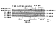
- the thickness (minimum thickness) of the thinnest portion of the SUS plate 131 is observed by observing the cross section (see FIG. 4) in the stacking direction (Z direction) of the cross section along the rolling direction of the pressure welding material 130 immediately after clad rolling.
- the thickness (minimum thickness t13 min) of the thinnest portion of the SUS plate 133 was obtained.
- any one of 13 types of pressure contact loads P (4.0 ⁇ 10 3 N / mm (pressure contact condition 1) or more and 7.8 ⁇ 10 3 N / mm (pressure contact condition 13) or less) shown in Table 1
- the strip-like press-contacting material 130 produced with the press-contact load P of 10 ten test areas in the range (length) of 15 mm in the rolling direction were obtained. At this time, five points were randomly obtained in the vicinity of both end portions in the rolling direction of the band-like pressure-contacting material 130.
- the minimum thickness t12 min of the SUS plate 131 and the minimum thickness t13 min of the SUS plate 133 are acquired, and the 10 minimum thicknesses t12 min and 10 minimum thicknesses t13 min are collectively averaged.
- the minimum thickness t ⁇ min of the SUS plates (SUS plates 131 and 133) in the pressure-contacting material 130 was used. Therefore, the above-mentioned minimum thickness t ⁇ min is based on the measurement values of the 20 thicknesses obtained from the pressure-contacting material 130.
- the thickness of five places randomly selected in the SUS board 131 was measured and averaged about each of ten test area
- the thicknesses of five randomly selected points on the SUS plate 133 were measured and averaged to obtain an average thickness t13avg of the SUS plate 133.
- the five average thicknesses t12avg and five average thicknesses t13avg obtained from the ten test areas were collectively averaged to obtain the average thickness t ⁇ avg of the SUS plate (SUS plates 131 and 133) of the pressure-contact material 130. Therefore, the above-mentioned average thickness t ⁇ avg is based on the measured values of the thickness of 100 pieces obtained from the pressure welding material 130.
- FIG. 7 and FIG. 8 show a cross-sectional photograph of the pressure-contact material under pressure-contact condition 3 and a part of a cross-sectional photograph of the pressure-contact material under pressure-contact condition 13, respectively.
- FIGS. 7 and 8 three different portions of the same rolling material are stacked in the stacking direction.
- the criteria for evaluation in Table 1 are judged based on whether the ratio of the minimum thickness to the average thickness of the SUS layer in the final product is 70% or more.
- the ratio of the minimum thickness to the average thickness of the SUS layer in the final product of this clad material was 70% (0.175 mm)
- no crack occurred when the ratio of the minimum thickness to the average thickness of the SUS layer in the final product of the clad material is 60 percent (0.150 mm), a crack may occur.
- the thickness ratio R ⁇ 1 shown in Table 1 defines the thickness ratio R ⁇ 2 from another viewpoint (minimum thickness t ⁇ min with respect to the entire cladding material).
- the thickness ratio R ⁇ 2 is a ratio of the thickness of the minimum thickness t ⁇ min to the average thickness t ⁇ avg of the SUS plate immediately after clad rolling.
- the thickness ratios R ⁇ 1 and R ⁇ 2 shown in Table 1 are ratios of stages in the process of producing the final product. Although the thickness of the entire clad material and the thickness of each layer differ between the stage in the process of making the final product and the final product, theoretically, the ratio of the thickness of each layer to the thickness of the entire clad material does not change. The ratio of the minimum thickness to the average thickness does not change.
- the ratio of the minimum thickness to the average thickness of the SUS layer of the final product is less than 70% even if R ⁇ 2 in the process of making the final product is 70% or more.
- the evaluation of the resulting clad material is x (improper).
- R ⁇ 2 is 85% or more
- the ratio of the minimum thickness to the average thickness of the SUS layer of the final product can surely be 70% or more by further rolling (intermediate rolling and finish rolling) after clad rolling
- the evaluation of the clad material is evaluated as ⁇ (suitable) because of its high property.
- the minimum thickness of the first layer It is believed that the thickness and the minimum thickness of the third layer will be less than 70% of the average thickness of the first layer and the average thickness of the third layer, respectively. Therefore, the pressure contact conditions 1 to 3 are marked with x (not suitable) as the evaluation.
- Rz1 is 22.0% or more (more than 20.8% and 21% or more) in a pressure-welded material which is rolled and joined under a pressure contact load P of 4.4 ⁇ 10 3 N / mm or more under pressure welding conditions 4 to 13.
- R ⁇ 2 was 88.0% or more (more than 83.2% and 84% or more). It is considered that this is because the sufficient pressing load P of 4.4 ⁇ 10 3 N / mm or more suppressed the rolling of each layer so as to cause nonuniform plastic deformation.
- the pressure-welded materials of the pressure-welding conditions 4 to 13 are clad materials as final products.
- the minimum thickness of the first layer and the minimum thickness of the third layer are considered to be 70% or more of the average thickness of the first layer and the average thickness of the third layer, respectively. Therefore, the pressure contact conditions 4 to 13 are marked with ⁇ (appropriate) as the evaluation.
- the values of thickness ratio R ⁇ 1 and thickness ratio R ⁇ 2 of the pressure-welded material subjected to rolling bonding with a pressure-contact load P of 6.7 ⁇ 10 3 N / mm or more under pressure-contacting condition 10 are 6 of pressure-contacting condition 9
- the value was smaller than the values of R ⁇ 1 and R ⁇ 2 of the pressure-welded material which was subjected to the rolling bonding with the pressure-contacting load P of not less than 0 ⁇ 10 3 N / mm.
- the values of R ⁇ 1 and R ⁇ 2 of the pressure-welded material subjected to rolling and joining under pressure welding condition P of 7.8 ⁇ 10 3 N / mm or more under pressure welding condition 13 are 7.3 ⁇ 10 3 N / mm or more of pressure welding condition 12
- the thickness ratio R ⁇ 1 and the thickness ratio R ⁇ 2 of the pressure-welded materials subjected to rolling bonding with the pressure-contacting load P are smaller than the values. The result is considered as follows.
- the force P0 applied to the work roller 103a is represented by the product of the pressure load P and the length L of the roller surface (see the above equation (1)). Therefore, when the length L of the roller surface is constant as in the first embodiment, the press-contact load P and the force P0 applied to the work roller 103a are in a proportional relationship. That is, as the pressing load P increases, the force P0 applied to the work roller 103a also increases. From this point of view, it is considered that the value of the thickness h2 of the pressure-contacting material 130 at the outlet side of the rolling roller 103 fluctuates with the fluctuation of the force P0, and R ⁇ 1 and R ⁇ 2 happen to be small under the influence.
- the thickness h2 of the pressure-contacting material 130 at the outlet side of the rolling roller 103 decreases, the plastic deformation ratio of each layer increases. Accordingly, the uniformity of the thickness h2 of the pressure-contacting material 130 on the outlet side of the rolling roller 103 is difficult to obtain, and the uniformity of the thickness of each layer is also difficult to obtain. As a result, uniformity of thickness h 2, thickness ratio R ⁇ 1 and thickness ratio R ⁇ 2 of pressure-contacting material 130 on the outlet side of rolling roller 103 becomes difficult to obtain, and may show small values or large values. However, although it becomes difficult to obtain uniformity, for example, as can be seen by comparing the result of pressure contact condition 4 with the result of pressure contact condition 13, thickness ratio R ⁇ 1 and thickness ratio R ⁇ 2 themselves are gradually increased by increasing the pressure load. It is getting bigger.
- the change tendency of the value of R ⁇ 1 of the press-contact material to the press-contact load P shown in Table 1 is approximately a linear approximate curve having an inclination of about 0.87 and an intercept of about 17.5 (suitable for data having a simple linear relationship) Can be represented by a straight line).
- the change tendency of the value of R ⁇ 2 of the press-contacting material with respect to the press-contact load P shown in Table 1 can be generally expressed by a linear approximate curve having an inclination of about 3.46 and an intercept of about 69.8. Therefore, there is a positive correlation between the pressure contact load P and the values of R ⁇ 1 and R ⁇ 2 of the pressure contact material, and it can be confirmed that the values of R ⁇ 1 and R ⁇ 2 of the pressure contact material increase as the pressure contact load P increases.
- the degree of corrugation (the size of the corrugation) at the interface is clearly different between the pressure-welded material marked with x (not suitable) and the pressure-welded material marked with ⁇ (suitable) as evaluation.
- the degree of wave of the interface when the minimum thickness to the average thickness is small (the values of thickness ratio R ⁇ 2 and R ⁇ 2 are small) in the pressure contact material, the wave amplitude at the interface becomes large, and as a result, the wave of the interface It is known that the degree increases (more waves). That is, by increasing the pressure contact load, the degree of undulation of the interface is improved.
- a clad material of a comparative example to the inventive example was produced. Specifically, a strip-like Cu plate made of Cu or a Cu alloy and in a state where the structure was sufficiently softened was prepared. In addition, temper rolling was not performed with respect to a strip
- clad welding is performed by rolling and joining using a rolling roller.
- the rolling bonding was performed under the pressure load P of 4.3 ⁇ 10 3 N / mm (pressure contact condition 3 of the first embodiment).
- the thickness change (rolling reduction) of the pressure-contacting material before and after clad rolling in the comparative example was the same as in the inventive example.
- the thicknesses of five places randomly selected in the SUS layer 31 were measured and averaged to obtain an average thickness t2avg of the SUS layer 31.
- the thicknesses of five places randomly selected in the SUS layer 33 were measured and averaged to obtain an average thickness t3avg of the SUS layer 33.
- the five average thicknesses t2avg and five average thicknesses t3avg obtained from the ten test areas are collectively averaged to obtain the average thickness t ⁇ avg of the SUS layer (SUS layers 31 and 33) of the clad material 30. Therefore, the above-mentioned average thickness t ⁇ avg is based on the measured values of the thickness of 100 pieces obtained from the clad material 30.
- the results are shown by so-called box and whisker plots.
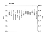
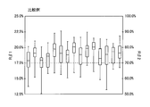
- the box and whisker plot of the inventive example and the box and whisker plot of the comparative example are shown in FIG. 9 and FIG. 10, respectively.
- the clad material of the example of the present invention it has been confirmed that the occurrence of a place where the thickness is excessively small in the SUS layer (the first layer and the third layer) made of stainless steel is suppressed. Further, it was confirmed that the first quartile of R ⁇ 1 in each clad material is 20% or more, and the first quartile of R ⁇ 2 is 80.0% or more. From this, it has been confirmed that it is possible to reliably suppress the occurrence of a place where the thickness is excessively small in the SUS layer in many clad materials.
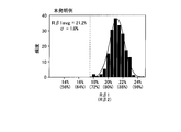
- the standard deviation ⁇ of R ⁇ 1 in the clad material of the example of the present invention was 1.0% (1.5% or less), and the variation in R ⁇ 1 was small. As a result, it has been confirmed that it is possible to suppress the occurrence of variations in properties such as mechanical strength in products (chassis and the like) manufactured from the clad material of the example of the present invention.
- the standard deviation ⁇ of R ⁇ 1 in the clad material of the comparative example was 1.7% (value exceeding 1.5%), and the variation of R ⁇ 1 was large. As a result, it has been confirmed that variations in characteristics such as mechanical strength are likely to occur in products (chassis and the like) manufactured from the clad material of the comparative example.
- R.alpha.1 and R.alpha.2 in the pressure-contacting material of pressure-contact condition 4 of the first embodiment (made with pressure-contacting load within the scope of the present invention (claim 4)) and pressure-contacting material of pressure-contacting condition 6 (claim 4 of the present invention) R.alpha.1 and R.alpha.2 in the pressure contact load within the range of the above were respectively the same value. Therefore, even if R.beta.1 and R.beta.2 are measured in the same manner as the second embodiment using the pressure welding material of the pressure welding condition 4, the measurement in the second embodiment performed using the pressure welding material of the pressure welding condition 6 It can be inferred that results substantially similar to R ⁇ 1 and R ⁇ 2 can be obtained.
- the minimum thickness in the stacking direction of the first layer and the minimum thickness in the stacking direction of the third layer are respectively the first layer If the average thickness in the stacking direction and the average thickness in the stacking direction of the third layer are 70% or more and less than 100% (the thickness ratio R ⁇ 2 is 70% or more and less than 100%), welding is performed when welding the cladding material to another member While being able to suppress that intensity
- the pressure contact condition 3 pressure contact load: 4.3 ⁇ 10 3 N / mm
- R ⁇ 2 minimum thickness of the SUS layer
- the pressure contact condition 6 pressure contact load: 4.9 ⁇ 10 3 N / mm
- the thickness ratio R ⁇ 2 after finish rolling was determined for the examples. Then, as shown in FIGS.
- the thickness ratio R ⁇ 2 after finish rolling is 70% or more in all the test materials, while in the comparative example, the thicknesses after finish rolling in all the test materials The portion where the ratio R ⁇ 2 was less than 70% occurred. From this, in the clad material manufactured under the pressure contact conditions 1 and 2 having the thickness ratio R ⁇ 2 smaller than the pressure contact condition 3 (pressure contact load: 4.3 ⁇ 10 3 N / mm), the thickness ratio R ⁇ 2 (SUS after finish rolling) If the minimum thickness of the layer is smaller than the pressure contact condition 3, it can easily be conceived. Therefore, in Table 1, since the pressure contact condition 3 is x, both the pressure contact conditions 1 and 2 are x.
- the crystal grain size of the Cu layer was measured based on the comparative method of JIS H 0501 for the clad materials of the present invention example and the comparative example in the second embodiment. Further, by performing a tensile strength test according to JIS Z 2241 on the clad materials of the invention examples and comparative examples, the tensile strength (force at break) and 0.2% proof stress as mechanical strength are obtained. (A force at an elongation of 0.2%) and an elongation as a processability ((Length at break-Length before test) / Length before test) x 100 (%)) were measured. Moreover, the relative magnetic permeability of the clad material of this invention example and a comparative example was measured as a magnetic characteristic. The measurement results are shown in Table 2.
- the thickness of the pressure-welded material (pressure-welded material 130) after clad rolling is a clad material (clad material 30) as a final product.
- clad material 30 As a final product of a thickness level, such as 1.0 mm or less, 0.5 mm or less, 0.3 mm or less, and further 0.2 mm or less.
- a thickness level such as 1.0 mm or less, 0.5 mm or less, 0.3 mm or less, and further 0.2 mm or less.
- temper rolling In order to perform clad rolling easily and reliably, it is preferable to perform temper rolling. Further, in order to reduce the product-to-product difference in the thickness of the clad material, it is preferable to perform intermediate rolling and finish rolling.
Landscapes
- Engineering & Computer Science (AREA)
- Mechanical Engineering (AREA)
- Chemical & Material Sciences (AREA)
- Materials Engineering (AREA)
- Metallurgy (AREA)
- Organic Chemistry (AREA)
- Physics & Mathematics (AREA)
- Thermal Sciences (AREA)
- Crystallography & Structural Chemistry (AREA)
- Pressure Welding/Diffusion-Bonding (AREA)
- Metal Rolling (AREA)
- Laminated Bodies (AREA)
Abstract
La présente invention concerne un matériau de gainage (30) pourvu : d'une première couche (31) qui est formée d'acier inoxydable ; d'une deuxième couche (32) qui est formée de Cu ou d'un alliage de Cu et qui est plaquée par laminage sur la première couche ; et d'une troisième couche (33) qui est formée d'acier inoxydable et est plaquée par laminage sur un côté, de la deuxième couche, à l'opposé de la première couche. Le matériau de gainage a une épaisseur globale d'au plus 1 mm. Dans une vue en coupe transversale le long de la direction d'empilement, l'épaisseur minimale de la première couche dans la direction d'empilement et l'épaisseur minimale de la troisième couche dans la direction d'empilement représentent 70 à 100 % de l'épaisseur moyenne de la première couche dans la direction d'empilement et 70 à 100 % de l'épaisseur moyenne de la troisième couche dans la direction d'empilement, respectivement.
Priority Applications (5)
| Application Number | Priority Date | Filing Date | Title |
|---|---|---|---|
| EP18845236.1A EP3666441B1 (fr) | 2017-08-09 | 2018-05-28 | Matériau de gainage et procédé de production de matériau de gainage |
| US16/634,228 US11607867B2 (en) | 2017-08-09 | 2018-05-28 | Clad material |
| CN201880048287.1A CN110997211B (zh) | 2017-08-09 | 2018-05-28 | 包层材料和包层材料的制造方法 |
| KR1020207000405A KR102496226B1 (ko) | 2017-08-09 | 2018-05-28 | 클래드재 및 클래드재의 제조 방법 |
| US17/681,996 US11981107B2 (en) | 2017-08-09 | 2022-02-28 | Method for manufacturing clad material |
Applications Claiming Priority (2)
| Application Number | Priority Date | Filing Date | Title |
|---|---|---|---|
| JP2017-154136 | 2017-08-09 | ||
| JP2017154136A JP6358378B1 (ja) | 2017-08-09 | 2017-08-09 | クラッド材の製造方法 |
Related Child Applications (2)
| Application Number | Title | Priority Date | Filing Date |
|---|---|---|---|
| US16/634,228 A-371-Of-International US11607867B2 (en) | 2017-08-09 | 2018-05-28 | Clad material |
| US17/681,996 Division US11981107B2 (en) | 2017-08-09 | 2022-02-28 | Method for manufacturing clad material |
Publications (1)
| Publication Number | Publication Date |
|---|---|
| WO2019031027A1 true WO2019031027A1 (fr) | 2019-02-14 |
Family
ID=62904845
Family Applications (1)
| Application Number | Title | Priority Date | Filing Date |
|---|---|---|---|
| PCT/JP2018/020405 Ceased WO2019031027A1 (fr) | 2017-08-09 | 2018-05-28 | Matériau de gainage et procédé de production de matériau de gainage |
Country Status (6)
| Country | Link |
|---|---|
| US (2) | US11607867B2 (fr) |
| EP (1) | EP3666441B1 (fr) |
| JP (1) | JP6358378B1 (fr) |
| KR (1) | KR102496226B1 (fr) |
| CN (1) | CN110997211B (fr) |
| WO (1) | WO2019031027A1 (fr) |
Cited By (1)
| Publication number | Priority date | Publication date | Assignee | Title |
|---|---|---|---|---|
| WO2019187768A1 (fr) * | 2018-03-29 | 2019-10-03 | 古河電気工業株式会社 | Matériau plaqué, et procédé de fabrication de celui-ci |
Families Citing this family (2)
| Publication number | Priority date | Publication date | Assignee | Title |
|---|---|---|---|---|
| KR102286363B1 (ko) * | 2019-12-20 | 2021-08-05 | 주식회사 포스코 | 두께 편차가 균일한 클래드 박판의 제조방법 |
| KR102601845B1 (ko) * | 2021-11-09 | 2023-11-15 | 주식회사 디에스피 | 차량용 스피커 그릴 및 그 제조 방법 |
Citations (3)
| Publication number | Priority date | Publication date | Assignee | Title |
|---|---|---|---|---|
| JP2003105500A (ja) * | 2001-09-26 | 2003-04-09 | Nippon Metal Ind Co Ltd | ステンレス鋼/銅クラッドおよびその製造方法 |
| JP2005219478A (ja) | 2004-01-09 | 2005-08-18 | Nippon Steel Corp | クラッド板およびその製造方法 |
| JP5410646B1 (ja) * | 2012-07-10 | 2014-02-05 | 株式会社Neomaxマテリアル | シャーシおよびシャーシの製造方法 |
Family Cites Families (21)
| Publication number | Priority date | Publication date | Assignee | Title |
|---|---|---|---|---|
| JPS5410646B1 (fr) | 1969-05-19 | 1979-05-09 | ||
| US3923558A (en) * | 1974-02-25 | 1975-12-02 | Olin Corp | Copper base alloy |
| US3985589A (en) * | 1974-11-01 | 1976-10-12 | Olin Corporation | Processing copper base alloys |
| DE3506524A1 (de) * | 1985-02-25 | 1986-08-28 | Akzo Gmbh, 5600 Wuppertal | Flexible polyimid-mehrschichtlaminate |
| JPH05161985A (ja) * | 1991-12-13 | 1993-06-29 | Nippon Steel Corp | 複合電磁鋼板の製造方法 |
| US6783870B2 (en) * | 2000-10-16 | 2004-08-31 | Engineered Materials Solutions, Inc. | Self-brazing materials for elevated temperature applications |
| JP2005134073A (ja) | 2003-10-31 | 2005-05-26 | Denso Corp | プレート式熱交換器 |
| JP2008123964A (ja) | 2006-11-15 | 2008-05-29 | Hitachi Cable Ltd | 高強度・高導電性クラッド材及びその製造方法 |
| CN201105358Y (zh) * | 2007-09-07 | 2008-08-27 | 中国联合工程公司 | 一种金属带材的热复合装置 |
| WO2009041481A1 (fr) * | 2007-09-26 | 2009-04-02 | The Furukawa Electric Co., Ltd. | Matériau composite de gaine en argent pour des contacts mobiles et processus pour fabriquer ce matériau |
| JP5212572B2 (ja) * | 2010-06-02 | 2013-06-19 | 新日鐵住金株式会社 | クラッド材 |
| JP5306418B2 (ja) * | 2010-07-09 | 2013-10-02 | 日新製鋼株式会社 | 銅被覆鋼箔、負極用電極及び電池 |
| KR20140114059A (ko) * | 2012-02-24 | 2014-09-25 | 가부시키가이샤 고베 세이코쇼 | 구리 합금 |
| CN202895810U (zh) * | 2012-09-04 | 2013-04-24 | 无锡银荣板业有限公司 | 铜/不锈钢/铜多层复合材料结构 |
| KR20140066413A (ko) * | 2012-11-23 | 2014-06-02 | 한국기계연구원 | 상온 접합력이 향상된 클래드 판재의 제조방법 및 이를 통해 제조된 클래드 판재 |
| CN102974611B (zh) * | 2012-11-28 | 2015-07-08 | 上海实达精密不锈钢有限公司 | 一种柔性太阳能电池基板不锈钢精密钢带成型方法 |
| CN103538313A (zh) * | 2012-12-03 | 2014-01-29 | 黎汉东 | 一种新型热轧钛-铝-不锈钢复合板及其生产方法和用途 |
| JP5965418B2 (ja) | 2014-01-09 | 2016-08-03 | 株式会社日立金属ネオマテリアル | シャーシおよび携帯機器 |
| CN103736729B (zh) * | 2014-01-22 | 2015-07-29 | 太原科技大学 | 一种轧制制备金属复合板带的方法 |
| KR101653742B1 (ko) * | 2015-06-19 | 2016-09-06 | 주식회사 한국클래드텍 | 클래드판의 연속 제조 방법 및 장치 |
| JP6609590B2 (ja) * | 2017-03-30 | 2019-11-20 | Jx金属株式会社 | 層状組織を有する高強度チタン銅条および箔 |
-
2017
- 2017-08-09 JP JP2017154136A patent/JP6358378B1/ja active Active
-
2018
- 2018-05-28 WO PCT/JP2018/020405 patent/WO2019031027A1/fr not_active Ceased
- 2018-05-28 CN CN201880048287.1A patent/CN110997211B/zh active Active
- 2018-05-28 KR KR1020207000405A patent/KR102496226B1/ko active Active
- 2018-05-28 US US16/634,228 patent/US11607867B2/en active Active
- 2018-05-28 EP EP18845236.1A patent/EP3666441B1/fr active Active
-
2022
- 2022-02-28 US US17/681,996 patent/US11981107B2/en active Active
Patent Citations (3)
| Publication number | Priority date | Publication date | Assignee | Title |
|---|---|---|---|---|
| JP2003105500A (ja) * | 2001-09-26 | 2003-04-09 | Nippon Metal Ind Co Ltd | ステンレス鋼/銅クラッドおよびその製造方法 |
| JP2005219478A (ja) | 2004-01-09 | 2005-08-18 | Nippon Steel Corp | クラッド板およびその製造方法 |
| JP5410646B1 (ja) * | 2012-07-10 | 2014-02-05 | 株式会社Neomaxマテリアル | シャーシおよびシャーシの製造方法 |
Non-Patent Citations (2)
| Title |
|---|
| "Plate Rolling", 25 October 1960, CORONA PUBLISHING CO., LTD. |
| See also references of EP3666441A4 |
Cited By (2)
| Publication number | Priority date | Publication date | Assignee | Title |
|---|---|---|---|---|
| WO2019187768A1 (fr) * | 2018-03-29 | 2019-10-03 | 古河電気工業株式会社 | Matériau plaqué, et procédé de fabrication de celui-ci |
| JP6599059B1 (ja) * | 2018-03-29 | 2019-10-30 | 古河電気工業株式会社 | クラッド材及びその製造方法 |
Also Published As
| Publication number | Publication date |
|---|---|
| KR20200038925A (ko) | 2020-04-14 |
| EP3666441A4 (fr) | 2021-04-21 |
| KR102496226B1 (ko) | 2023-02-06 |
| US20220176676A1 (en) | 2022-06-09 |
| CN110997211A (zh) | 2020-04-10 |
| EP3666441A1 (fr) | 2020-06-17 |
| EP3666441B1 (fr) | 2023-08-09 |
| US11607867B2 (en) | 2023-03-21 |
| JP2019031036A (ja) | 2019-02-28 |
| US11981107B2 (en) | 2024-05-14 |
| JP6358378B1 (ja) | 2018-07-18 |
| US20210086478A1 (en) | 2021-03-25 |
| CN110997211B (zh) | 2023-01-10 |
Similar Documents
| Publication | Publication Date | Title |
|---|---|---|
| US11981107B2 (en) | Method for manufacturing clad material | |
| US10953630B2 (en) | Method for manufacturing clad material | |
| US10864596B2 (en) | Metal laminate material and production method therefor | |
| TWI692534B (zh) | 複層型電磁鋼板 | |
| US6312834B1 (en) | Clad material and method of manufacturing the material | |
| JP6645490B2 (ja) | クラッド材およびクラッド材の製造方法 | |
| CN105814226A (zh) | Cvt用环部件及其制造方法 | |
| JP4479053B2 (ja) | 高強度かつ平坦性に優れたステンレス鋼板とその製造方法 | |
| JP2019098536A (ja) | クラッド材およびクラッド材の製造方法 | |
| JP2020028884A (ja) | クラッド材の製造方法およびクラッド材 | |
| JP6536386B2 (ja) | 制振鋼板およびその製造方法 | |
| JP5326097B2 (ja) | 界面剥離破断、ネッキング破断のない強度−延性バランスにすぐれた複層鋼 | |
| JP2008123964A (ja) | 高強度・高導電性クラッド材及びその製造方法 | |
| CN119387316B (zh) | 一种沉淀硬化马氏体sus630不锈钢冷轧钢带板形控制方法 | |
| JP2019112718A (ja) | 積層薄板の製造方法及び積層薄板 | |
| CN118475467A (zh) | 复合板 | |
| JP2017127905A (ja) | エッジ圧延装置、圧延装置及び圧延方法 | |
| KR20170065981A (ko) | 클래드 강판 및 그 제조 방법 | |
| JP2013112829A (ja) | オーステナイト系ステンレス鋼及びこれを用いたプレスプレート | |
| JP2007245176A (ja) | 接合体の製造方法 | |
| JP2019002052A (ja) | クラッド材の製造方法 | |
| JP2011088156A (ja) | 異形断面条材の製造方法 |
Legal Events
| Date | Code | Title | Description |
|---|---|---|---|
| 121 | Ep: the epo has been informed by wipo that ep was designated in this application |
Ref document number: 18845236 Country of ref document: EP Kind code of ref document: A1 |
|
| NENP | Non-entry into the national phase |
Ref country code: DE |
|
| ENP | Entry into the national phase |
Ref document number: 2018845236 Country of ref document: EP Effective date: 20200309 |