WO2019031049A1 - Moteur - Google Patents
Moteur Download PDFInfo
- Publication number
- WO2019031049A1 WO2019031049A1 PCT/JP2018/022133 JP2018022133W WO2019031049A1 WO 2019031049 A1 WO2019031049 A1 WO 2019031049A1 JP 2018022133 W JP2018022133 W JP 2018022133W WO 2019031049 A1 WO2019031049 A1 WO 2019031049A1
- Authority
- WO
- WIPO (PCT)
- Prior art keywords
- bearing holder
- contact surface
- bearing
- inner circumferential
- cylindrical portion
- Prior art date
- Legal status (The legal status is an assumption and is not a legal conclusion. Google has not performed a legal analysis and makes no representation as to the accuracy of the status listed.)
- Ceased
Links
Images

Classifications
-
- H—ELECTRICITY
- H02—GENERATION; CONVERSION OR DISTRIBUTION OF ELECTRIC POWER
- H02K—DYNAMO-ELECTRIC MACHINES
- H02K11/00—Structural association of dynamo-electric machines with electric components or with devices for shielding, monitoring or protection
- H02K11/30—Structural association with control circuits or drive circuits
-
- H—ELECTRICITY
- H02—GENERATION; CONVERSION OR DISTRIBUTION OF ELECTRIC POWER
- H02K—DYNAMO-ELECTRIC MACHINES
- H02K5/00—Casings; Enclosures; Supports
- H02K5/04—Casings or enclosures characterised by the shape, form or construction thereof
- H02K5/16—Means for supporting bearings, e.g. insulating supports or means for fitting bearings in the bearing-shields
Definitions
- the present invention relates to a motor.
- a motor in which a flange for holding a bearing and a housing are fixed by shrink fitting (e.g., Patent Document 1).
- one aspect of the present invention aims to provide a motor that can hold a bearing holder on a housing while suppressing deformation of the housing.
- a rotor having a shaft disposed along a central axis extending in the vertical direction, the rotor rotating around the central axis, and a stator opposed to the rotor with a gap in between.
- a housing having a cylindrical portion surrounding the stator from outside in the radial direction; a bearing rotatably supporting the shaft; and a bearing holder fixed to the cylindrical portion and supporting the bearing, the bearing holder A holding portion for holding the bearing, a flat portion extending along a plane orthogonal to the central axis on the radially outer side of the holding portion, and an extending portion extending along the axial direction from the outer edge of the flat portion , And the extension portion is disposed along the circumferential direction and has a first contact surface that faces radially outward and contacts the inner peripheral surface of the cylindrical portion, and the first contact surface Is Serial arranged shift relative to the flat portion in the axial direction, at least partially overlap in the axial direction relative to the holding portion.
- a motor that can hold a bearing on a housing while suppressing deformation of the housing.
- FIG. 1 is a cross-sectional view of a motor according to one embodiment.
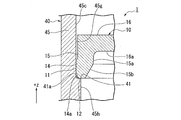
- FIG. 2 is an enlarged view of region II of FIG.
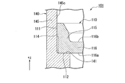
- FIG. 3 is a partial cross-sectional view of the motor of the first modification.
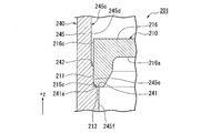
- FIG. 4 is a partial cross-sectional view of a motor of Modification 2.
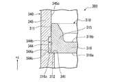
- FIG. 5 is a partial cross-sectional view of a motor according to a third modification.
- the Z axis is shown as appropriate.
- the Z-axis direction of each drawing is a direction parallel to the axial direction of the central axis J shown in FIG.
- the positive side in the Z-axis direction (+ Z side, one side) is referred to as “upper side”
- the negative side in the Z-axis direction ( ⁇ Z side, other side) as “lower side”.
- the upper and lower sides are directions used merely for the purpose of explanation, and do not limit the actual positional relationship or direction.
- a direction (Z-axis direction) parallel to the central axis J is simply referred to as “axial direction” or “vertical direction”, and a radial direction centered on the central axis J is simply referred to as “radial direction”.
- the circumferential direction around the central axis J that is, around the axis of the central axis J, is simply referred to as “circumferential direction”.
- plane view means a state viewed from the axial direction.
- FIG. 1 is a cross-sectional view of a motor 1 of the present embodiment.
- the motor 1 includes a rotor 20 having a shaft 21, a stator 30, a bus bar unit 60, a housing 40, an upper bearing 6A, a lower bearing 6B, and a bearing holder 10.
- the motor 1 is connected to an external device (control unit) 9 by an external connection terminal 61 a extending upward from the bus bar unit 60.
- the rotation of the rotor 20 is controlled by the external device 9 of the motor 1.
- the rotor 20 rotates around the central axis J.
- the rotor 20 has a shaft 21, a rotor core 24, and a rotor magnet 23.
- the shaft 21 is disposed along the central axis J around a central axis J extending in the vertical direction (axial direction).
- the shaft 21 is rotatably supported around the central axis J by the upper bearing 6A and the lower bearing 6B.
- the rotor core 24 is fixed to the shaft 21.
- the rotor core 24 circumferentially surrounds the shaft 21.
- the rotor magnet 23 is fixed to the rotor core 24. More specifically, the rotor magnet 23 is fixed to the outer surface along the circumferential direction of the rotor core 24. The rotor core 24 and the rotor magnet 23 rotate with the shaft 21.
- the stator 30 faces the rotor 20 in the radial direction with a gap therebetween, and surrounds the radially outer side of the rotor 20.
- the stator 30 has a stator core 31, an insulator 32, and a coil 33.
- the insulator 32 is made of an insulating material.
- the insulator 32 covers at least a part of the stator core 31.
- the coil 33 is configured by winding a coil wire (not shown).
- the coil wire is wound around the teeth portion of the stator core 31 via the insulator 32. The end of the coil wire is drawn upward.
- the bus bar unit 60 is located between the stator 30 and the bearing holder 10 in the axial direction. That is, the bus bar unit 60 is located above the stator 30 and below the bearing holder 10.
- the bus bar unit 60 has a plurality of bus bars 61 and a bus bar holder 62 for holding the bus bars 61.
- the coil wire drawn from the stator 30 is connected to the bus bar 61.
- a part of the bus bar 61 penetrates the bearing holder 10 as an external connection terminal 61 a and extends upward.
- the external connection terminal 61 a is connected to an external device 9 that controls energization of the coil 33 of the stator 30.
- the bus bar unit 60 may be located on the upper side of the bearing holder 10.
- the upper bearing 6A rotatably supports the upper end 21a of the shaft 21.
- the upper bearing 6A is located above the stator 30.
- the upper bearing 6A is supported by the bearing holder 10.
- the lower bearing 6B rotatably supports the lower end 21b of the shaft 21.
- the lower bearing 6B is located below the stator 30.
- the lower bearing 6B is supported by the lower bearing holding portion 48 of the housing 40.
- the upper bearing 6A and the lower bearing 6B are ball bearings.
- the types of upper bearing 6A and lower bearing 6B are not particularly limited, and may be other types of bearings.
- the housing 40 is in the form of a tube that opens to the upper side (+ Z side).
- the housing 40 accommodates the rotor 20 and the stator 30.
- the housing 40 has a cylindrical portion 45, a bottom portion 49, and a lower bearing holding portion 48.
- the housing 40 may be a cylindrical member having no bottom 49. In this case, a bearing holder for holding a bearing is separately attached to the lower opening of the housing 40.
- the cylindrical portion 45 surrounds the stator 30 from the radially outer side.
- the cylindrical portion 45 is cylindrical.
- the inner circumferential surface 45 c of the cylindrical portion 45 is provided with a stepped surface (first stepped surface) 41 facing upward.
- a region above the step surface 41 in the inner circumferential surface 45 c is referred to as a first inner circumferential surface 45 g.
- a region below the step surface 41 is referred to as a second inner circumferential surface 45h.
- the inner diameter of the first inner circumferential surface 45g is larger than the inner diameter of the second inner circumferential surface 45h.
- the stator 30 is fixed to the second inner circumferential surface 45 h.
- the inner circumferential surface 45c of the cylindrical portion 45 is processed by a cutting process such as boring or lathing. After the inner circumferential surface 45c is machined in the axial direction with the uniform inner diameter of the second inner circumferential surface 45h in the cutting process, the first inner circumferential surface 45g above the step surface 41 is processed in the cutting process It is molded with For this reason, a corner R portion 44 a is formed at the radially outer end of the step surface 41.
- the housing 40 is manufactured by processing the above-mentioned internal peripheral surface 45c, for example, after shape
- a housing space A for housing the external device 9 is provided on the inner side in the radial direction of the cylindrical portion 45 and above the bearing holder 10.
- the external device 9 is connected to the external connection terminal 61 a of the motor 1 in the housing space A.
- a part of the external device 9 is enclosed in the cylindrical portion 45, and the connection between the external device 9 and the external connection terminal 61a is protected.
- the cylindrical portion 45 surrounds the housing space A from the outer side in the radial direction, so there is a possibility that the housing space A may be distorted if the amount of deformation of the cylindrical portion 45 becomes large. As a result, the storage state of the external device 9 becomes unstable, and the connection state between the external device 9 and the motor 1 may be affected. As will be described later, according to the motor 1 of the present embodiment, the amount of deformation of the cylindrical portion 45 is reduced, whereby the connection state between the external device 9 and the motor 1 can be stabilized.
- a housing area 45 c 1 which is the inner circumferential surface 45 c of the cylindrical portion 45 and surrounds the housing space A, contacts the external device 9.
- the deformation of the cylindrical portion 45 directly affects the assembling accuracy of the external device 9 and the motor 1. Therefore, when a part of the inner circumferential surface 45c contacts the external device 9, not only the connection between the external device 9 and the motor 1 is stabilized but also the motor is reduced by reducing the amount of deformation of the cylindrical portion 45. The positioning accuracy of the external device 9 with respect to 1 can be enhanced.
- the bottom portion 49 is located at the lower end of the cylindrical portion 45.
- the bottom 49 is located below the stator 30.
- the lower bearing holding portion 48 is located at the center of the bottom portion 49 in plan view.
- the lower bearing holder 48 holds the lower bearing 6B.
- the lower bearing holding portion 48 has a cylindrical portion 48 a extending in the axial direction centering on the central axis J, and a lower end protruding portion 48 b extending inward in the radial direction from the lower end of the cylindrical portion 48 a.
- a hole 48c penetrating in the axial direction is provided at the center of the lower end protrusion 48b in plan view.
- the bearing holder 10 is located on the upper side (+ Z side) of the stator 30.
- the bearing holder 10 supports the upper bearing 6A.
- the plan view shape of the bearing holder 10 is, for example, a circular shape concentric with the central axis J.
- the bearing holder 10 is fixed to the inner circumferential surface 45 c of the cylindrical portion 45 by shrink fitting. For this reason, radial inward stress is applied to the bearing holder 10 from the inner peripheral surface 45 c of the cylindrical portion 45. On the other hand, radial outward stress is applied to the cylindrical portion 45 from the bearing holder 10.
- the bearing holder 10 has an upper bearing holding portion (holding portion) 18, a curved portion 17, a flat portion 16, and an extending portion 15.
- the upper bearing holding portion (holding portion) 18, the curved portion 17, the flat portion 16 and the extension portion 15 are disposed in this order from the radially inner side to the outer side.
- the upper bearing holder 18 holds the upper bearing 6A.
- the upper bearing holder 18 is located at the center of the bearing holder 10 in plan view.
- the upper bearing holding portion 18 has a cylindrical portion 18a extending in the axial direction centering on the central axis J, and an upper end projecting portion 18b extending inward in the radial direction from the upper end of the cylindrical portion 18a.
- the upper end protrusion 18b positions the upper bearing 6A in the vertical direction.
- a hole 18c penetrating in the axial direction is provided at the center of the upper end protrusion 18b in a plan view. The upper end portion of the shaft 21 is inserted into the hole 18c.
- the curved portion 17 is located between the flat portion 16 and the upper bearing holding portion 18 in the radial direction.
- the curved portion 17 extends obliquely upward as it goes radially outward from the middle of the axial direction of the cylindrical portion 18 a of the upper bearing holding portion 18.
- a recessed groove 17 a is provided in the bearing holder 10 above the curved portion 17. That is, the bearing holder 10 is provided with a recessed groove 17 a located between the flat portion 16 and the upper bearing holding portion 18 in the radial direction.
- the recessed groove 17a opens in the axial direction (upper side in the present embodiment).
- the recessed groove 17a extends along the circumferential direction.
- the bearing holder 10 can be easily bent in the axial direction in the lower curved portion 17 of the recessed groove 17a.
- radial inward stress is applied to the bearing holder 10 from the cylindrical portion 45.
- the load applied to the upper bearing holding portion 18 is reduced by the elastic deformation of the curved portion 17 with respect to the radially inward stress and the bending of the bearing holder 10.
- the reliability of holding the upper bearing 6A in the upper bearing holding portion 18 can be enhanced.
- the concave groove 17a of this embodiment is opened to the upper side, even in the case of opening to the lower side, the curved portion 17 can be preferentially deformed to reduce the stress applied to the upper bearing holding portion 18 .
- the flat portion 16 is located radially outward of the upper bearing holding portion 18 and the curved portion 17.
- the flat portion 16 extends along a plane orthogonal to the central axis J.
- the flat portion 16 has a disk shape centered on the central axis J in plan view.
- the extension 15 extends in the axial direction from the outer edge of the flat portion 16. In the present embodiment, the extension 15 extends downward with respect to the flat portion 16.
- the extending portion 15 extends in a tubular shape along the circumferential direction.
- the extending portion 15 radially faces the inner circumferential surface 45 c of the cylindrical portion 45.
- the extension 15 partially overlaps the upper bearing holder 18 in the axial direction.
- FIG. 2 is an enlarged view of the region II of FIG.
- the extension part 15 has a convex part 14.
- the convex portion 14 protrudes radially outward from a surface facing the radially outer side of the extending portion 15.
- the convex portion 14 is located in the lower region of the extending portion 15.
- the convex portion 14 extends along the circumferential direction.
- the convex portion 14 has a first contact surface 11 directed radially outward, a second contact surface 12 directed downward, and a first tapered portion (chamfered portion) 14 a. That is, the bearing holder 10 has a first contact surface 11, a second contact surface 12, and a first tapered portion 14a. Moreover, the extension part 15 has the 1st contact surface 11, the 2nd contact surface 12, and the 1st taper part 14a. The first contact surface 11 contacts the inner circumferential surface 45 c of the cylindrical portion 45. The second contact surface 12 contacts the step surface 41 of the cylindrical portion 45. The first tapered portion 14 a is located between the first contact surface 11 and the second contact surface 12. The first contact surface 11, the second contact surface 12, and the first tapered portion 14a extend along the circumferential direction with a uniform width.
- the upper end of the first contact surface 11 is located below the lower surface 16 a of the flat portion 16. That is, the first contact surface 11 is disposed to be offset axially downward with respect to the flat portion 16.
- the bearing holder 10 and the housing 40 are fixed by shrink fitting. For this reason, radial inward stress is applied to the bearing holder 10 from the first contact surface 11.
- the first contact surface overlaps the flat portion in the axial direction. In this case, since the flat portion is stretched against the radially inward stress applied from the cylindrical portion to the bearing holder, the bearing holder does not deform unless the flat portion is buckled.
- the first contact surface 11 is provided in the extension portion extending downward from the outer edge of the flat portion 16.
- the first contact surface 11 is disposed to be axially offset with respect to the flat portion 16.
- the flat portion 16 and the cylindrical portion 45 face each other in the radial direction via a gap. Therefore, the radially inward stress applied from the cylindrical portion 45 to the bearing holder 10 is not directly applied to the flat portion 16. The radially inward stress is applied in the direction of bending the flat portion 16 in the axial direction, and the deformation of the bearing holder 10 is facilitated.
- the reaction force applied from the bearing holder 10 to the housing 40 can be reduced, and the amount of deformation of the housing 40 can be suppressed.
- Such an effect can be obtained not only when the bearing holder 10 and the housing 40 are fixed by shrink fitting but also when they are fixed by press fitting.
- the first contact surface 11 axially overlaps at least a part of the upper bearing holder 18. In addition, at least a portion of the first contact surface 11 axially overlaps the upper bearing 6A. According to the present embodiment, since the first contact surface 11 and the upper bearing holding portion 18 axially overlap, the bearing holder 10 can be miniaturized in the axial direction.
- the first contact surface 11 extends continuously along the circumferential direction.
- a plurality of first contact surfaces 11 may be discretely arranged along the circumferential direction. In this case, it is preferable that three or more first contact surfaces 11 be provided at equal intervals around the central axis J.
- the second contact surface 12 faces downward and contacts the step surface 41. Thereby, when a downward stress is applied to the bearing holder 10, the step surface 41 supports the bearing holder 10 from the lower side, and it is possible to suppress the movement of the bearing holder 10 downward. As a result, it is possible to suppress the bearing holder 10 from coming off the housing 40.
- the second contact surface 12 can position the bearing holder 10 in the axial direction with respect to the housing 40 by contacting the step surface 41 facing downward.
- the bearing holder 10 is disposed inside the cylindrical portion 45 in a state in which the cylindrical portion 45 of the housing 40 is heated to thermally expand the cylindrical portion 45.
- the bearing holder 10 is positioned in the axial direction with respect to the housing 40 by bringing the second contact surface 12 into contact with the step surface 41. Further, by cooling the cylindrical portion 45, the cylindrical portion 45 is contracted to fix the cylindrical portion and the bearing holder 10 in contact with each other.
- the inner diameter of the inner peripheral surface 45 c of the cylindrical portion 45 above the step surface 41 is larger than the outer diameter of the bearing holder 10 when the cylindrical portion 45 expands in the shrink fitting process.
- the inner diameter below the step surface 41 is smaller than the outer diameter of the bearing holder 10 even when the cylindrical portion 45 expands in the shrink fitting process.
- the second contact surface 12 is provided on the convex portion 14 in the present embodiment.
- the second contact surface 12 may be provided on any surface facing the lower side of the bearing holder 10 as long as the second contact surface 12 faces the step surface 41 in the axial direction.
- the first taper portion 14 a is provided at a ridge portion between the first contact surface 11 and the second contact surface 12.
- the first tapered portion 14a inclines inward in the radial direction toward the lower side.
- the first tapered portion 14a is formed by chamfering.
- the corner R portion 41 a is necessarily provided on the radial outside of the step surface 41.
- the first tapered portion 14 a faces the corner R portion 41 a of the step surface 41.
- the first tapered portion 14 a by providing the first tapered portion 14 a in the convex portion 14, interference of the convex portion 14 with the corner R portion 41 a can be suppressed. As a result, the positioning accuracy in the axial direction of the bearing holder 10 due to the contact between the second contact surface 12 and the step surface 41 can be enhanced.
- the first tapered portion 14a linearly inclines and extends from the inner side to the outer side in the radial direction has been described.
- the first tapered portion 14a may be curved as long as it has a tapered shape that suppresses interference with the corner R portion 41a.
- the first taper portion 14a may be an R surface having a curvature radius larger than that of the corner R portion 41a.
- the extension portion 15 has an inner side surface 15a facing inward in the radial direction.
- the second tapered portion 15b is provided on the inner side surface 15a.
- the second tapered portion 15b is located at the lower end portion of the inner side surface 15a.
- the second tapered portion 15b is inclined radially outward as it goes downward.
- the second tapered portion 15 b is located radially inward of the first contact surface 11.
- the axial length of the second tapered portion 15b is longer than the axial length of the first tapered portion 14a.
- the second tapered portion 15b in the extension portion 15, the rigidity of the extension portion 15 with respect to the radially inward stress applied to the first contact surface 11 To make the extension part 15 easy to deform.
- the stress applied from the bearing holder 10 to the housing 40 can be alleviated, and the deformation of the housing 40 can be suppressed.
- the second tapered portion 15b is longer in the axial direction than the first tapered portion 14a, so that the length of the first contact surface 11 along the axial direction is sufficiently secured, and the rigidity of the extended portion 15 is obtained. Can be lowered enough.
- the volume of the space under the bearing holder 10 can be widened by providing the second tapered portion 15 b in the extension portion 15.
- the bearing holder 10 can be disposed close to the stator 30 while securing a space for disposing the bus bar unit 60 below the bearing holder 10.
- the dimension along the axial direction of the entire motor 1 can be reduced.
- the extending portion 15 extends downward from the outer edge of the flat portion 16. Therefore, the first contact surface 11 provided in the extension portion 15 and disposed in the axial direction with respect to the flat portion 16 is located below the flat portion 16. Therefore, the distance between the first contact surface 11 and the upper end of the cylindrical portion 45 can be secured as compared with the case where the extending portion 15 extends upward with respect to the flat portion 16.
- the cylindrical portion 45 receives a reaction force from the first contact surface 11 and deforms radially outward. The amount of deformation of the cylindrical portion 45 decreases with distance from the first contact surface 11.
- the motor 1 is positioned in contact with the external device 9 (see FIG. 1) in the vicinity of the upper end of the cylindrical portion 45. By arranging the upper end of the cylindrical portion 45 as far as possible from the first contact surface 11, deformation of the upper end of the cylindrical portion can be suppressed. As a result, the positioning accuracy of the motor 1 with respect to the external device 9 can be enhanced.
- extension portion 15 extends downward with respect to the flat portion 16, so that the upper region of the bearing holder 10 can be widely secured as compared with the case where the extension portion 15 extends upward.
- at least a part of the extension portion 15 axially overlaps the upper bearing holding portion 18 (see FIG. 1). Therefore, the upper bearing holding portion 18 is also located lower than the flat portion 16 together with the extending portion 15. Therefore, the upper region of the bearing holder 10 can be widened even near the radial center of the bearing holder 10.
- the bearing holder 10 and the housing 40 are fixed by shrink fitting.
- the bearing holder 10 and the housing 40 may be fixed by press fitting.
- the first contact surface 11 of the bearing holder 10 and the inner circumferential surface 45c of the housing 40 may be rubbed to cause contamination.
- the inner peripheral surface 45 c of the housing 40 is not rubbed by the bearing holder 10. Therefore, the inner peripheral surface 45 c of the cylindrical portion 45 has the same surface roughness between the upper side of the bearing holder 10 and the lower side of the bearing holder 10.
- the bearing holder 10 and the housing 40 are both made of a metal material. Moreover, it is preferable that the bearing holder 10 and the housing 40 consist of the same material. When the bearing holder 10 and the housing 40 are the same material, it means that the alloy compositions of the metal materials of the other are the same or substantially the same. In this case, the linear expansion coefficients of the bearing holder 10 and the housing 40 can be made the same or substantially the same.
- the parts of the motor 1 may thermally expand or shrink due to temperature changes caused by the surrounding environment or the drive of the motor 1. According to the present embodiment, by configuring the bearing holder 10 and the housing 40 with the same material, a sufficient holding force is maintained even when the bearing holder 10 and the housing 40 thermally expand or shrink. Can.
- FIG. 3 is a partial cross-sectional view of a motor 101 of Modification 1.
- the motor 101 of this modification differs in the fitting structure of the bearing holder 110 and the housing 140 compared with the above-mentioned embodiment.
- symbol is attached
- the housing 140 has a cylindrical portion 145 provided with an inner circumferential surface 145 c facing inward in the radial direction.
- the inner circumferential surface 145 c of the cylindrical portion 145 is provided with a stepped surface (first stepped surface) 141 facing upward.
- the inner diameter of the inner circumferential surface 145 c above the step surface 141 is larger than the inner diameter of the step surface 141 below.
- the bearing holder 110 has a flat portion 116 extending along a plane orthogonal to the central axis J, and an extending portion 115 located radially outward of the flat portion 116.
- the bearing holder 110 also has an upper bearing holding portion (holding portion) 18 and a bending portion 17 as in the above-described embodiment, although not shown in FIG.
- the upper bearing holding portion (holding portion) 18 and the bending portion 17 are located radially inward of the flat portion 116.
- the extension 115 of this modification extends upward with respect to the flat portion 116.
- the upper bearing holder 18 preferably extends in the same direction as the extension 115. That is, it is preferable that the upper bearing holding portion 18 of this modification is disposed to extend upward with respect to the flat portion 116.
- the extension portion 115 extends upward along the axial direction from the outer edge of the flat portion 116.
- the extension portion 115 extends in a tubular shape along the circumferential direction.
- the extension portion 115 radially faces the inner circumferential surface 145 c of the cylindrical portion 145.
- the extension portion 115 has a convex portion 114.
- the convex portion 114 protrudes radially outward from a surface facing the radially outer side of the extension portion 115.
- the convex portion 114 is located in the upper region of the extension portion 115.
- the convex portion 114 extends along the circumferential direction.
- the convex portion 114 has a first contact surface 111 facing radially outward.
- the first contact surface 111 contacts the inner circumferential surface 145 c of the cylindrical portion 145. That is, the extension part 115 has the first contact surface 111.
- the first contact surface 111 extends along the circumferential direction with a uniform width.
- the lower end of the first contact surface 111 is located above the upper surface 116 b of the flat portion 116. That is, the first contact surface 111 is disposed offset to the upper side in the axial direction with respect to the flat portion 116. Accordingly, as in the above-described embodiment, the deformation of the bearing holder 110 is facilitated, and the deformation of the housing 140 can be reduced.
- a second contact surface 112 is provided on the lower surface 116 a of the flat portion 116. That is, the flat portion 116 has the second contact surface 112.
- the second contact surface 112 faces downward and contacts the step surface 141 of the cylindrical portion 145. Accordingly, when a downward stress is applied to the bearing holder 110, the step surface 141 supports the bearing holder 110 from the lower side, and it is possible to suppress the movement of the bearing holder 110 downward. Further, by bringing the second contact surface 112 into contact with the step surface 141, the bearing holder 110 can be positioned in the axial direction with respect to the housing 140 in the shrink fitting process or the press fitting process.
- the extension 115 extends upward with respect to the flat portion 116, the lower surface 116a of the flat portion 116 can be provided with the second contact surface 112 in contact with the step surface 141.
- the extension 115 is limited in radial thickness in order to be easily deformed with respect to radial inward stress. For this reason, when providing a 2nd contact surface in an extension part, the dimension of the radial direction of a 2nd contact surface is restrict
- the flat portion 116 is provided with the second contact surface 112 the second contact surface can be made sufficiently wide to stably support the bearing holder 110 against downward stress.
- FIG. 4 is a partial cross-sectional view of a motor 201 of Modification 2.
- the motor 201 of this modification differs in the fitting structure of the bearing holder 210 and the housing 240 compared with the above-mentioned embodiment.
- symbol is attached
- the housing 240 has a cylindrical portion 245 provided with an inner circumferential surface 245 c facing inward in the radial direction.
- a first step surface 241 and a second step surface 242 facing upward are provided on the inner circumferential surface 245 c of the cylindrical portion 245.
- the second step surface 242 is located above the first step surface 241.
- a region above the second step surface 242 is referred to as a first surface (upper inner circumferential surface) 245d.
- a region between the second step surface 242 and the first step surface 241 is referred to as a second surface (lower side inner circumferential surface) 245e.
- a region under the first step surface 241 is referred to as a third surface 245f. That is, on the inner circumferential surface 245 c, the first surface located above the second step surface 242, and the second surface located below the second step surface 242 and above the first step surface 241.
- a surface and a third surface located below the first step surface 241 are provided.
- the first surface 245 d, the second surface 245 e, and the third surface 245 f are arranged in this order from the upper side to the lower side.
- the inner diameter of the inner circumferential surface 245c decreases in the order of the first surface 245d, the second surface 245e, and the third surface 245f. That is, the second surface 245 e has a larger inner diameter than the first surface 245 d.
- the third surface 245f has a larger inner diameter than the first surface 245d and the second surface 245e.
- the bearing holder 210 has a flat portion 216 extending along a plane orthogonal to the central axis J, and an extension portion 215 located radially outward of the flat portion 216.
- the bearing holder 210 also has an upper bearing holding portion (holding portion) 18 and a bending portion 17 as in the above-described embodiment, although not shown in FIG.
- the upper bearing holding portion (holding portion) 18 and the bending portion 17 are located radially inward of the flat portion 216.
- the lower surface 216 a of the flat portion 216 is located above the second step surface 242 of the cylindrical portion 245.
- the flat portion 216 has an outer circumferential surface 216 c facing radially outward.
- the outer circumferential surface 216 c faces the first surface 245 d of the inner circumferential surface 245 c in the radial direction with a gap in between.
- the extension portion 215 extends downward from the outer edge of the flat portion 216 in the axial direction.
- the extension part 215 extends in a tubular shape along the circumferential direction.
- the extension portion 215 radially faces the inner circumferential surface 245 c of the cylindrical portion 245.
- a second contact surface 212 facing downward is provided. That is, the extension part 215 has the second contact surface 212.
- the second contact surface 212 contacts the first stepped surface 241.
- the second contact surface 212 extends along the circumferential direction with a uniform width.
- the second contact surface 212 is provided in the extension portion 215, and contacts the first step surface 241 at the second contact surface 212. For this reason, when a downward stress is applied to the bearing holder 210, the first step surface 241 supports the bearing holder 210 from the lower side, thereby suppressing the movement of the bearing holder 210 downward. Further, by bringing the second contact surface 212 into contact with the first step surface 241, the bearing holder 210 can be positioned in the axial direction with respect to the housing 240 in the shrink fitting process or the press fitting process.
- a first contact surface 211 is provided on a surface of the extension portion 215 facing radially outward.
- the first contact surface 211 faces radially outward.
- the first contact surface 211 extends along the circumferential direction with a uniform width.
- the first contact surface 211 contacts the second surface 245 e of the inner peripheral surface 245 c of the cylindrical portion 245.
- the extension portion 215 has a first tapered portion 215c located between the first contact surface 211 and the second contact surface 212 and inclined radially inward toward the lower side.
- the first tapered portion 215 c faces the corner R portion 241 a of the first step surface 241.
- the lower surface 216 a of the flat portion 216 is located above the second step surface 242. Therefore, the upper end of the first contact surface 211 is located below the lower surface 216 a of the flat portion 216. That is, the first contact surface 211 is arranged to be offset axially downward with respect to the flat portion 216. Further, the flat portion 216 faces the first surface 245 d of the inner circumferential surface 245 c via a gap. According to the present modification, the first contact surface 211 is provided on an extension extending downward from the outer edge of the flat portion 216. Further, a gap is provided between the bearing holder 210 and the housing 240 at the radially outer side of the flat portion 216.
- the radially inward stress applied from the cylindrical portion 245 to the bearing holder 210 is not directly applied to the flat portion 216.
- the radially inward stress is applied in the direction of bending the flat portion 216 in the axial direction, and the deformation of the bearing holder 210 is facilitated. As a result, the deformation of the housing 240 is reduced.
- FIG. 5 is a partial cross-sectional view of a motor 301 of Modification 3. As shown in FIG. The motor 301 of this modification differs in the fitting structure of the bearing holder 310 and the housing 340 compared with the above-mentioned embodiment. In addition, about the component of the aspect same as the above-mentioned embodiment, the same code
- the housing 340 has a cylindrical portion 345 provided with an inner circumferential surface 345 c facing inward in the radial direction.
- the inner circumferential surface 345 c of the cylindrical portion 345 is provided with a groove portion 344 which is a groove extending along the circumferential direction.
- the groove portion 344 has a bottom surface 344a facing inward in the radial direction, a first groove wall surface 344b located on the upper side of the bottom surface 344a and facing downward, and a second groove wall surface 344c located below the bottom surface 344a and facing upward , Composed of
- the inner circumferential surface 345c is provided with a stepped surface (first stepped surface) 341 facing upward.
- the step surface 341 extends with a uniform width along the circumferential direction.
- the step surface 341 is located below the groove 344. Further, the step surface 341 is located in the same plane as the second groove wall surface 344c of the groove portion 344 and is continuous with the second groove wall surface 344c. That is, the step surface 341 is a surface that extends the second groove wall surface 344c of the groove portion 344 radially inward.
- the inner circumferential surface 345 c has an inner diameter above the groove 344 larger than an inner diameter below the groove 344.
- the bearing holder 310 has a flat portion 316 extending along a plane orthogonal to the central axis J, and an extension portion 315 located radially outward of the flat portion 316. Further, the bearing holder 310 has an upper bearing holding portion (holding portion) 18 and a bending portion 17 as in the above-described embodiment, although not shown in FIG. The upper bearing holding portion (holding portion) 18 and the curved portion 17 are located radially inward of the flat portion 316. In addition, as described later, the extension portion 315 of this modification extends upward with respect to the flat portion 316. From the viewpoint of reducing the size of the bearing holder 310 in the axial direction, the upper bearing holder 18 preferably extends in the same direction as the extension 315. That is, it is preferable that the upper bearing holding portion 18 of this modification is disposed to extend upward with respect to the flat portion 316.
- the upper surface 316 b of the flat portion 316 is located below the first groove wall surface 344 b of the groove 344.
- the flat portion 316 has an outer circumferential surface 316 c facing radially outward.
- the outer circumferential surface 316 c is opposed to the bottom surface 344 a of the groove 344 in the radial direction via a gap.
- the lower surface 316 a of the flat portion 316 is provided with a second contact surface 312 facing downward. That is, the flat portion 316 has the second contact surface 312.
- the second contact surface 312 contacts the step surface 341 of the cylindrical portion 345.
- the step surface 341 supports the bearing holder 310 from the lower side, and it is possible to suppress the movement of the bearing holder 310 downward.
- the bearing holder 310 can be positioned in the axial direction with respect to the housing 340 in the shrink fitting process or the press fitting process.
- the extension portion 315 extends upward along the axial direction from the outer edge of the flat portion 316.
- the extension part 315 extends cylindrically along the circumferential direction.
- the extension portion 315 radially faces the inner circumferential surface 345 c of the cylindrical portion 345.
- a first contact surface 311 is provided on the radially outward surface of the extension portion 315.
- the first contact surface 311 faces radially outward.
- the first contact surface 311 extends along the circumferential direction with a uniform width.
- the first contact surface 311 contacts the inner circumferential surface 345 c of the cylindrical portion 345 at the upper side of the groove 344. That is, the first contact surface 311 contacts the inner circumferential surface 345 c at a portion of the inner circumferential surface 345 c of the cylindrical portion 345 other than the groove 344.
- the upper surface 316 b of the flat portion 316 is located below the first groove wall surface 344 b of the groove 344. Therefore, the lower end of the first contact surface 311 is located above the upper surface 316 b of the flat portion 316. That is, the first contact surface 311 is disposed offset to the upper side in the axial direction with respect to the flat portion 316. Further, the flat portion 316 faces the bottom surface 344a of the groove portion 344 of the inner circumferential surface 345c with a gap therebetween. According to the present modification, the first contact surface 311 is provided on an extension extending downward from the outer edge of the flat portion 316.
- the bearing holder 310 is provided with a gap from the housing 340 at the radially outer side of the flat portion 316. Accordingly, as in the above-described embodiment, the deformation of the bearing holder 310 is facilitated, and the deformation of the housing 340 can be reduced.
- step surface (first step surface), 45, 145, 245, 345 ... cylindrical portion 45c, 145c, 245c, 45c: inner circumferential surface
- 242 second step surface
- 245d first surface (upper inner circumferential surface)
- 245e second surface (lower inner circumferential surface)
- 245f third surface
- 344 groove portion, 344a ... bottom, J ... central axis
Landscapes
- Engineering & Computer Science (AREA)
- Power Engineering (AREA)
- Motor Or Generator Frames (AREA)
Abstract
La présente invention concerne un moteur qui est pourvu : d'un rotor qui possède un arbre disposé le long de l'axe central s'étendant dans la direction verticale et qui tourne autour de l'axe central ; d'un stator qui fait face au rotor par l'intermédiaire d'un espace dans la direction radiale ; d'un boîtier qui possède une partie cylindrique entourant le stator à partir du côté radialement externe ; d'un palier qui soutient de manière rotative l'arbre ; d'un support de palier qui soutient le palier fixé à la partie cylindrique. Le support de palier présente : une partie de retenue qui retient le palier ; une partie plate qui s'étend le long d'une surface plate perpendiculaire à l'axe central sur le côté radialement externe de la partie de retenue ; une partie d'extension qui s'étend dans la direction axiale à partir du bord externe de la partie plate. La partie d'extension possède une première surface de contact qui est disposée dans la direction circonférentielle, qui est orientée radialement vers l'extérieur et qui est en contact avec la surface circonférentielle interne de la partie cylindrique. La première surface de contact est disposée de manière à être déplacée de la partie plate dans la direction axiale, et chevauche, au moins partiellement, la partie de retenue dans la direction axiale.
Priority Applications (1)
| Application Number | Priority Date | Filing Date | Title |
|---|---|---|---|
| CN201890001027.4U CN211880221U (zh) | 2017-08-09 | 2018-06-11 | 马达 |
Applications Claiming Priority (2)
| Application Number | Priority Date | Filing Date | Title |
|---|---|---|---|
| JP2017154582 | 2017-08-09 | ||
| JP2017-154582 | 2017-08-09 |
Publications (1)
| Publication Number | Publication Date |
|---|---|
| WO2019031049A1 true WO2019031049A1 (fr) | 2019-02-14 |
Family
ID=65271598
Family Applications (1)
| Application Number | Title | Priority Date | Filing Date |
|---|---|---|---|
| PCT/JP2018/022133 Ceased WO2019031049A1 (fr) | 2017-08-09 | 2018-06-11 | Moteur |
Country Status (2)
| Country | Link |
|---|---|
| CN (1) | CN211880221U (fr) |
| WO (1) | WO2019031049A1 (fr) |
Citations (8)
| Publication number | Priority date | Publication date | Assignee | Title |
|---|---|---|---|---|
| JPS5674955U (fr) * | 1979-11-13 | 1981-06-19 | ||
| JPS57130554U (fr) * | 1981-02-10 | 1982-08-14 | ||
| JPH0279155U (fr) * | 1988-12-07 | 1990-06-18 | ||
| JPH062962U (ja) * | 1992-06-08 | 1994-01-14 | 自動車電機工業株式会社 | 小型モータ |
| JPH10262352A (ja) * | 1997-03-18 | 1998-09-29 | Tokyo Parts Ind Co Ltd | 扁平モータと同モータの機器実装給電方法 |
| JP2007267568A (ja) * | 2006-03-30 | 2007-10-11 | Mitsubishi Electric Corp | モールド電動機及び空気調和機 |
| WO2016063347A1 (fr) * | 2014-10-21 | 2016-04-28 | 三菱電機株式会社 | Moteur électrique et ventilateur |
| WO2017026491A1 (fr) * | 2015-08-10 | 2017-02-16 | 日本電産株式会社 | Moteur |
-
2018
- 2018-06-11 CN CN201890001027.4U patent/CN211880221U/zh active Active
- 2018-06-11 WO PCT/JP2018/022133 patent/WO2019031049A1/fr not_active Ceased
Patent Citations (8)
| Publication number | Priority date | Publication date | Assignee | Title |
|---|---|---|---|---|
| JPS5674955U (fr) * | 1979-11-13 | 1981-06-19 | ||
| JPS57130554U (fr) * | 1981-02-10 | 1982-08-14 | ||
| JPH0279155U (fr) * | 1988-12-07 | 1990-06-18 | ||
| JPH062962U (ja) * | 1992-06-08 | 1994-01-14 | 自動車電機工業株式会社 | 小型モータ |
| JPH10262352A (ja) * | 1997-03-18 | 1998-09-29 | Tokyo Parts Ind Co Ltd | 扁平モータと同モータの機器実装給電方法 |
| JP2007267568A (ja) * | 2006-03-30 | 2007-10-11 | Mitsubishi Electric Corp | モールド電動機及び空気調和機 |
| WO2016063347A1 (fr) * | 2014-10-21 | 2016-04-28 | 三菱電機株式会社 | Moteur électrique et ventilateur |
| WO2017026491A1 (fr) * | 2015-08-10 | 2017-02-16 | 日本電産株式会社 | Moteur |
Also Published As
| Publication number | Publication date |
|---|---|
| CN211880221U (zh) | 2020-11-06 |
Similar Documents
| Publication | Publication Date | Title |
|---|---|---|
| CN110462989B (zh) | 马达 | |
| US20150170701A1 (en) | Motor and disk drive apparatus | |
| US9837113B2 (en) | Spindle motor and disk drive apparatus | |
| CN108141113B (zh) | 马达 | |
| CN212412923U (zh) | 马达 | |
| EP2963782B1 (fr) | Dispositif à moteur | |
| JP6924934B2 (ja) | 巻線固定構造体、及び電動機 | |
| US20060028078A1 (en) | Small motor | |
| JP5465391B2 (ja) | モータ | |
| JPWO2018147052A1 (ja) | モータ用ロータ、モータ及びモータ用ロータの製造方法 | |
| US20200153294A1 (en) | Rotor and motor | |
| WO2019031049A1 (fr) | Moteur | |
| JP5466962B2 (ja) | ブラシレスモータ及びその製造方法 | |
| US10566865B2 (en) | Motor | |
| JPWO2019111879A1 (ja) | モータ付きギアシステム | |
| JP2017184560A (ja) | モータ及びモータの製造方法 | |
| US11418083B2 (en) | Motor | |
| US8432077B2 (en) | Bearing holder and spindle motor having the same | |
| JP6816546B2 (ja) | モータおよびモータの製造方法 | |
| JP6958197B2 (ja) | モータおよびモータユニット | |
| WO2012008150A1 (fr) | Structure de fixation et appareil d'entraînement | |
| US20190214052A1 (en) | Motor | |
| JP2014079059A (ja) | モータのステータ、およびその製造方法 | |
| JP6234702B2 (ja) | モータ | |
| JP2019062608A (ja) | ステータ |
Legal Events
| Date | Code | Title | Description |
|---|---|---|---|
| 121 | Ep: the epo has been informed by wipo that ep was designated in this application |
Ref document number: 18844427 Country of ref document: EP Kind code of ref document: A1 |
|
| NENP | Non-entry into the national phase |
Ref country code: DE |
|
| 122 | Ep: pct application non-entry in european phase |
Ref document number: 18844427 Country of ref document: EP Kind code of ref document: A1 |
|
| NENP | Non-entry into the national phase |
Ref country code: JP |