WO2019031104A1 - 非空気入りタイヤ - Google Patents
非空気入りタイヤ Download PDFInfo
- Publication number
- WO2019031104A1 WO2019031104A1 PCT/JP2018/025022 JP2018025022W WO2019031104A1 WO 2019031104 A1 WO2019031104 A1 WO 2019031104A1 JP 2018025022 W JP2018025022 W JP 2018025022W WO 2019031104 A1 WO2019031104 A1 WO 2019031104A1
- Authority
- WO
- WIPO (PCT)
- Prior art keywords
- pneumatic tire
- wheel
- rim
- tread
- disc
- Prior art date
- Legal status (The legal status is an assumption and is not a legal conclusion. Google has not performed a legal analysis and makes no representation as to the accuracy of the status listed.)
- Ceased
Links
Images


Classifications
-
- B—PERFORMING OPERATIONS; TRANSPORTING
- B60—VEHICLES IN GENERAL
- B60B—VEHICLE WHEELS; CASTORS; AXLES FOR WHEELS OR CASTORS; INCREASING WHEEL ADHESION
- B60B3/00—Disc wheels, i.e. wheels with load-supporting disc body
- B60B3/02—Disc wheels, i.e. wheels with load-supporting disc body with a single disc body integral with rim
-
- B—PERFORMING OPERATIONS; TRANSPORTING
- B60—VEHICLES IN GENERAL
- B60B—VEHICLE WHEELS; CASTORS; AXLES FOR WHEELS OR CASTORS; INCREASING WHEEL ADHESION
- B60B21/00—Rims
- B60B21/02—Rims characterised by transverse section
-
- B—PERFORMING OPERATIONS; TRANSPORTING
- B60—VEHICLES IN GENERAL
- B60B—VEHICLE WHEELS; CASTORS; AXLES FOR WHEELS OR CASTORS; INCREASING WHEEL ADHESION
- B60B21/00—Rims
- B60B21/10—Rims characterised by the form of tyre-seat or flange, e.g. corrugated
-
- B—PERFORMING OPERATIONS; TRANSPORTING
- B60—VEHICLES IN GENERAL
- B60B—VEHICLE WHEELS; CASTORS; AXLES FOR WHEELS OR CASTORS; INCREASING WHEEL ADHESION
- B60B23/00—Attaching rim to wheel body
-
- B—PERFORMING OPERATIONS; TRANSPORTING
- B60—VEHICLES IN GENERAL
- B60B—VEHICLE WHEELS; CASTORS; AXLES FOR WHEELS OR CASTORS; INCREASING WHEEL ADHESION
- B60B3/00—Disc wheels, i.e. wheels with load-supporting disc body
- B60B3/04—Disc wheels, i.e. wheels with load-supporting disc body with a single disc body not integral with rim, i.e. disc body and rim being manufactured independently and then permanently attached to each other in a second step, e.g. by welding
-
- B—PERFORMING OPERATIONS; TRANSPORTING
- B60—VEHICLES IN GENERAL
- B60B—VEHICLE WHEELS; CASTORS; AXLES FOR WHEELS OR CASTORS; INCREASING WHEEL ADHESION
- B60B9/00—Wheels of high resiliency, e.g. with conical interacting pressure-surfaces
- B60B9/26—Wheels of high resiliency, e.g. with conical interacting pressure-surfaces comprising resilient spokes
-
- B—PERFORMING OPERATIONS; TRANSPORTING
- B60—VEHICLES IN GENERAL
- B60C—VEHICLE TYRES; TYRE INFLATION; TYRE CHANGING; CONNECTING VALVES TO INFLATABLE ELASTIC BODIES IN GENERAL; DEVICES OR ARRANGEMENTS RELATED TO TYRES
- B60C7/00—Non-inflatable or solid tyres
-
- B—PERFORMING OPERATIONS; TRANSPORTING
- B60—VEHICLES IN GENERAL
- B60C—VEHICLE TYRES; TYRE INFLATION; TYRE CHANGING; CONNECTING VALVES TO INFLATABLE ELASTIC BODIES IN GENERAL; DEVICES OR ARRANGEMENTS RELATED TO TYRES
- B60C7/00—Non-inflatable or solid tyres
- B60C7/10—Non-inflatable or solid tyres characterised by means for increasing resiliency
- B60C7/14—Non-inflatable or solid tyres characterised by means for increasing resiliency using springs
- B60C7/146—Non-inflatable or solid tyres characterised by means for increasing resiliency using springs extending substantially radially, e.g. like spokes
-
- B—PERFORMING OPERATIONS; TRANSPORTING
- B60—VEHICLES IN GENERAL
- B60B—VEHICLE WHEELS; CASTORS; AXLES FOR WHEELS OR CASTORS; INCREASING WHEEL ADHESION
- B60B2310/00—Manufacturing methods
- B60B2310/30—Manufacturing methods joining
- B60B2310/302—Manufacturing methods joining by welding
-
- B—PERFORMING OPERATIONS; TRANSPORTING
- B60—VEHICLES IN GENERAL
- B60B—VEHICLE WHEELS; CASTORS; AXLES FOR WHEELS OR CASTORS; INCREASING WHEEL ADHESION
- B60B3/00—Disc wheels, i.e. wheels with load-supporting disc body
-
- B—PERFORMING OPERATIONS; TRANSPORTING
- B60—VEHICLES IN GENERAL
- B60B—VEHICLE WHEELS; CASTORS; AXLES FOR WHEELS OR CASTORS; INCREASING WHEEL ADHESION
- B60B9/00—Wheels of high resiliency, e.g. with conical interacting pressure-surfaces
- B60B9/02—Wheels of high resiliency, e.g. with conical interacting pressure-surfaces using springs resiliently mounted bicycle rims
-
- B—PERFORMING OPERATIONS; TRANSPORTING
- B60—VEHICLES IN GENERAL
- B60C—VEHICLE TYRES; TYRE INFLATION; TYRE CHANGING; CONNECTING VALVES TO INFLATABLE ELASTIC BODIES IN GENERAL; DEVICES OR ARRANGEMENTS RELATED TO TYRES
- B60C7/00—Non-inflatable or solid tyres
- B60C7/10—Non-inflatable or solid tyres characterised by means for increasing resiliency
- B60C7/14—Non-inflatable or solid tyres characterised by means for increasing resiliency using springs
Definitions
- the present invention relates to a non-pneumatic tire having a tread portion, a wheel portion and a spoke portion.
- a typical tire is mounted on a wheel and filled with air (hereinafter referred to as "a pneumatic tire”).
- a pneumatic tire On the other hand, non-pneumatic tires that can be used without being filled with air are being adopted, particularly in small electric vehicles (MEVs). In this case, daily check of the air pressure is unnecessary, and there is an advantage that there is no concern of puncture.
- MEVs small electric vehicles
- the main object of the present invention is to provide a non-pneumatic tire which is excellent in response during turning of a vehicle.
- a cylindrical tread portion in contact with the ground, a wheel portion disposed radially inward of the tread portion, and a spoke portion interposed between the tread portion and the wheel portion
- the wheel portion has a disk portion to which an axle is connected, and a rim portion in which an inner circumferential side is connected to the disk portion and an outer circumferential side is joined to a spoke portion.
- a non-pneumatic tire is provided in which the average thickness of the disc portion is larger than the average thickness of the rim portion.
- the disc portion is relatively difficult to bend. Therefore, at the time of turning (cornering), the responsiveness is improved from the low speed range to the high speed range. For this reason, since it is what is called sporty driving
- the spoke portion has an inner annular portion to which the rim portion is joined, an outer annular portion provided with the tread portion, and a plurality of spokes integrally connecting the inner annular portion and the outer annular portion. It is preferable that it is. Since the spokes exert an elastic action, the external force during traveling is alleviated. Moreover, it becomes easy to join a wheel part and to provide a tread part.
- the wheel portion may be formed by joining the disc portion and the rim portion as separate members. In this case, it is possible individually to change the shape of the disc portion or to change the thickness and height of the rim portion. Therefore, it becomes easy to set the falling rigidity of the disk portion and the bending rigidity in the radial direction of the rim portion.
- the wheel portion may consist of a single member in which the disc portion and the rim portion are integrally provided. In this case, the joining operation is unnecessary. Moreover, for example, when a wheel part is produced from aluminum alloy wrought material, weight reduction can be achieved.
- the average thickness of the disk portion constituting the wheel portion is set larger than the average thickness of the rim portion similarly constituting the wheel portion.
- the disc portion becomes relatively difficult to bend, and since the component members of the wheel portion are mainly metal, there is almost no change in the spring constant accompanying the increase in rotational speed, so low speed during turning (cornering) In the region, transient characteristics similar to those of pneumatic tires are obtained, and in the high-speed region, the response is excellent. For this reason, it is possible to obtain a feeling of performing sporty driving.
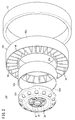
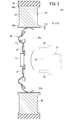
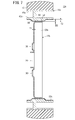
- FIG. 1 is an overall schematic perspective view of a non-pneumatic tire according to an embodiment of the present invention. It is a disassembled perspective view of the non-pneumatic tire of FIG. It is side surface sectional drawing of the non-pneumatic tire of FIG.
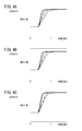
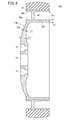
- FIGS. 4A to 4C are graphs showing transient characteristics of the cornering force for each vehicle speed of various tires. It is a graph which shows the relationship between the load and cornering power at the time of cornering of a vehicle. It is side surface sectional drawing of the non-pneumatic tire which concerns on another embodiment. It is side surface sectional drawing of the non-pneumatic tire which concerns on another embodiment.
- the non-pneumatic tire 10a includes a cylindrical tread ring 12 (tread portion), a wheel portion 14a disposed radially inward of the tread ring 12, a spoke portion connecting the tread ring 12 and the wheel portion 14a. And 16a.
- the tread ring 12 is formed of a rubber ring-shaped body, and the outer peripheral wall thereof is a contact surface.
- a tread groove (not shown) is formed on the contact surface in order to obtain sufficient grip even on a wet road surface.
- the wheel portion 14a has a disk-shaped disc portion 20a and a cylindrical rim portion 22a provided continuously in the radial direction of the disc portion 20a.
- a hub hole 24 is formed at the center of the disk portion 20a, and a front end portion 28 of an axle 26 shown by an imaginary line in FIG. 3 is inserted into the hub hole 24.
- a plurality of bolt insertion holes 30 are formed around the hub hole 24.
- a bolt portion 34 provided on the axle 26 side is inserted into each bolt insertion hole 30, and the bolt portion 34 is fixed by a nut not shown.
- the disk portion 20a is manufactured by, for example, press forming a metal plate material similar to that of a conventional tire wheel, such as steel (steel), aluminum alloy, magnesium alloy and the like.
- One rim portion 22a is formed of a cylindrical body, and in this case, it is a separate member manufactured separately from the disc portion 20a.
- the rim 22a is curved so that the end faces contact each other, and the contact end faces are subjected to friction stir welding or It is obtained by being joined by an appropriate method such as welding.
- the outer edge portion of the disc portion 20a and the inner peripheral wall of the rim portion 22a are joined, for example, by welding or the like.
- the average thickness of the disk portion 20a is T1 and the average thickness of the rim portion 22a is T2 (see FIG. 3), the relationship of T1> T2 holds. That is, the average thickness T1 of the disk portion 20a is larger than the average thickness T2 of the rim portion 22a.
- the disk portion 20a and the rim portion 22a are each made of a metal plate material having substantially the same thickness. Therefore, the thickness of each of the disk portion 20a and the rim portion 22a is substantially constant over the entire area. For this reason, the relation of T1> T2 is established over the entire disc portion 20a and the rim portion 22a.
- the spokes 16a extend radially along the diameter of the non-pneumatic tire 10a, the annular outer annular portion 40a covered by the tread ring 12, the annular inner annular portion 42a joined to the rim portion 22a, and the annular portion And a plurality of spokes 44.
- the inner peripheral side of each spoke 44 is integrally connected with the inner annular portion 42a, and the outer peripheral side is integrally connected with the outer annular portion 40a.
- Such a spoke portion 16a is made of, for example, a polymer material such as a thermoplastic resin or a thermosetting resin.
- Preferred examples of the thermosetting resin include epoxy resins, phenol resins, urethane resins, silicone resins, polyimide resins, and melamine resins.
- the non-pneumatic tire 10a according to the present embodiment is basically configured as described above. Next, its function and effect will be described.
- the disc portion 20a and the rim portion 22a are separate members individually manufactured. Therefore, it is possible to change the shape of the disk portion 20a variously, and to change the thickness and height of the rim portion 22a variously. Therefore, it is particularly easy to set the falling rigidity of the disk portion 20a and the bending rigidity in the radial direction of the rim portion 22a.
- the non-pneumatic tire 10a configured as described above is attached to, for example, the axle 26 of the MEV, and contributes to traveling by being rotated via the axle 26 under the action of a motor.
- the tread ring 12 contacts the ground (road surface).
- the spokes 44 constituting the spoke portion 16a and the disk portion 20a constituting the wheel portion 14a receive a compressive bending force acting in the circumferential direction of the non-pneumatic tire 10a and bend in the rotational direction. That is, the spokes 44 and the disk portion 20a function as an elastic body.
- the cornering force is generated with a time delay when the slip angle of the tire changes rapidly due to the rapid steering operation. This phenomenon is known as a cornering transient characteristic and occurs due to the influence of the change speed of the slip angle, the lateral rigidity of the tire, and the traveling speed.
- FIGS. 4A to 4C show transient characteristics of cornering forces at 20 km / h, 40 km / h and 80 km / h, respectively, of a vehicle (MEV) equipped with various tires.
- the solid line in the figure indicates the slip angle input, and the broken line indicates the transient characteristic obtained for the non-pneumatic tire 10a.
- the one-dot chain line and the two-dot chain line are transient characteristics obtained for the non-pneumatic tire in which the average thickness T1 of the pneumatic tire and the disk portion 20a is smaller than the average thickness T2 of the rim portion 22a. . It can be understood from FIGS. 4A to 4C that the non-pneumatic tire 10a can obtain transient characteristics close to the slip angle input.
- the average thickness T1 of the disk portion 20a is larger than the average thickness T2 of the rim portion 22a. Therefore, the disk portion 20a is relatively difficult to bend. Therefore, the linear relationship shown in FIG. 5 is obtained between the load at the time of turning and the cornering power which is the increasing rate of the cornering force. The smaller the load, the lower the speed, and the larger the load, the higher the speed.
- Curve C in FIG. 5 is a result obtained for the pneumatic tire, and a straight line M indicated by a thin solid line is a result obtained for a non-pneumatic tire in which T1 ⁇ T2.
- straight lines L1, L2, L3, L4 indicated by thick solid lines, broken lines, alternate long and short dash lines, and alternate long and two short dash lines are non-pneumatic tires 10a and 10b according to the present embodiment (see FIG. 6) in which T1> T2. It is obtained.
- the straight lines L2 to L4 each have a separate type wheel portion 14a in which the disc portion 20a and the rim portion 22a are individually manufactured, and each T1 is 2.8 mm, 2.5 mm, 2.3 mm, and T2 is It is 2 mm, 2 mm, 2 mm.
- the wheel portion may be made of a single member integrally having a disc portion and a rim portion.
- a non-pneumatic tire 10b of such a configuration is shown in FIG.
- the same components as those shown in FIGS. 1 to 3 are denoted by the same reference numerals.
- Reference numerals 14b, 20b and 22b denote a wheel portion, a disc portion and a rim portion, respectively.
- the thickness of the disk portion 20b may be changed.
- the average thickness T1 may be calculated from the thickness (eg, T1 ′, T1 ′ ′, etc.) of each portion of the disk portion 20b, and the calculated value may be made larger than the average thickness T2 of the rim 22b. .
- the non-pneumatic tire 10c shown in FIG. 7 may be used.
- the wheel portion 14c has a flat disk portion 20c
- the spoke portion 16c has an inner annular portion 42c provided with a thick portion 50.
- An annular recess 52 is formed in the rim portion 22 c to correspond to the thick portion 50.
Landscapes
- Engineering & Computer Science (AREA)
- Mechanical Engineering (AREA)
- Tires In General (AREA)
Priority Applications (3)
| Application Number | Priority Date | Filing Date | Title |
|---|---|---|---|
| US16/637,290 US11535053B2 (en) | 2017-08-09 | 2018-07-02 | Non-pneumatic tire |
| EP18844116.6A EP3666548B1 (de) | 2017-08-09 | 2018-07-02 | Luftloser reifen |
| CN201880051706.7A CN110997351A (zh) | 2017-08-09 | 2018-07-02 | 非充气轮胎 |
Applications Claiming Priority (2)
| Application Number | Priority Date | Filing Date | Title |
|---|---|---|---|
| JP2017154593A JP2019031243A (ja) | 2017-08-09 | 2017-08-09 | 非空気入りタイヤ |
| JP2017-154593 | 2017-08-09 |
Publications (1)
| Publication Number | Publication Date |
|---|---|
| WO2019031104A1 true WO2019031104A1 (ja) | 2019-02-14 |
Family
ID=65271215
Family Applications (1)
| Application Number | Title | Priority Date | Filing Date |
|---|---|---|---|
| PCT/JP2018/025022 Ceased WO2019031104A1 (ja) | 2017-08-09 | 2018-07-02 | 非空気入りタイヤ |
Country Status (5)
| Country | Link |
|---|---|
| US (1) | US11535053B2 (de) |
| EP (1) | EP3666548B1 (de) |
| JP (1) | JP2019031243A (de) |
| CN (1) | CN110997351A (de) |
| WO (1) | WO2019031104A1 (de) |
Families Citing this family (1)
| Publication number | Priority date | Publication date | Assignee | Title |
|---|---|---|---|---|
| CN113427947B (zh) * | 2021-05-31 | 2022-06-17 | 广东粤港澳大湾区黄埔材料研究院 | 一种非充气轮胎的成型装置 |
Citations (7)
| Publication number | Priority date | Publication date | Assignee | Title |
|---|---|---|---|---|
| US20110272254A1 (en) * | 2005-06-13 | 2011-11-10 | Millenworks, Inc. | Variable Compliance Wheel |
| WO2013175914A1 (ja) * | 2012-05-24 | 2013-11-28 | 横浜ゴム株式会社 | タイヤ |
| JP2014118128A (ja) | 2012-12-19 | 2014-06-30 | Bridgestone Corp | 非空気入りタイヤ |
| WO2014188912A1 (ja) | 2013-05-22 | 2014-11-27 | 住友ゴム工業株式会社 | エアレスタイヤ、及びその製造方法 |
| JP2016041573A (ja) | 2014-08-13 | 2016-03-31 | ハンコック タイヤ カンパニー リミテッド | 乗り心地が向上された非空気入りタイヤ |
| WO2016116491A1 (fr) * | 2015-01-22 | 2016-07-28 | Compagnie Generale Des Etablissements Michelin | Dispositif de type pneumatique pour vehicule |
| WO2018007658A1 (es) * | 2016-07-06 | 2018-01-11 | Advantaria, Sl | Rueda mixta neumatica y no neumatica con seguridad aumentada |
Family Cites Families (16)
| Publication number | Priority date | Publication date | Assignee | Title |
|---|---|---|---|---|
| GB254187A (en) * | 1925-08-29 | 1926-07-01 | Michelin Et Cie Soc En Command | Improvements in metallic wheels for vehicles |
| FR1595036A (de) * | 1968-12-11 | 1970-06-08 | ||
| GB1581927A (en) * | 1976-04-07 | 1980-12-31 | Steel Stampings Ltd | Friction welding of vehicle wheels |
| US4832098A (en) * | 1984-04-16 | 1989-05-23 | The Uniroyal Goodrich Tire Company | Non-pneumatic tire with supporting and cushioning members |
| JPS63215328A (ja) * | 1987-02-28 | 1988-09-07 | Sumitomo Metal Ind Ltd | 自動車用ホイ−ル |
| CN2384794Y (zh) | 1999-06-24 | 2000-06-28 | 张兴毅 | 分离式免维护车轮 |
| US6736007B2 (en) * | 2000-10-31 | 2004-05-18 | Honda Giken Kogyo Kabushiki Kaisha | Assembling method for tire wheel assembly and assembling line for tire wheel assembly, and wheel and production method for wheel |
| JP4027200B2 (ja) * | 2002-03-22 | 2007-12-26 | 本田技研工業株式会社 | ホイール構造 |
| JP2008162495A (ja) * | 2006-12-28 | 2008-07-17 | Yokohama Rubber Co Ltd:The | 非空気式タイヤ |
| JP2008302782A (ja) * | 2007-06-06 | 2008-12-18 | Yokohama Rubber Co Ltd:The | 非空気入りタイヤ用ホイールおよび非空気入りタイヤ・ホイール組立体 |
| JP5208570B2 (ja) | 2008-04-30 | 2013-06-12 | 東洋ゴム工業株式会社 | 非空気圧タイヤ、リムホイール、及び車輪 |
| EP2544905B1 (de) * | 2010-03-12 | 2015-11-04 | Compagnie Générale des Etablissements Michelin | Strukturell gestütztes nicht pneumatisches rad mit durchgehender laufverstärkungsbaugruppe |
| US8567461B2 (en) * | 2010-08-12 | 2013-10-29 | The Boeing Company | Non-pneumatic survivable tire mounting system for conventional wheels |
| CN104417268A (zh) * | 2013-08-19 | 2015-03-18 | 陕西胜慧源信息科技有限公司 | 一种防滑防爆轮胎 |
| JP6383294B2 (ja) | 2015-01-13 | 2018-08-29 | 住友ゴム工業株式会社 | エアレスタイヤ |
| RU167034U1 (ru) * | 2016-07-14 | 2016-12-20 | федеральное государственное бюджетное образовательное учреждение высшего образования "Нижегородский государственный технический университет им. Р.Е. Алексеева" (НГТУ) | Автомобильная шина с упругими деформируемыми спицами |
-
2017
- 2017-08-09 JP JP2017154593A patent/JP2019031243A/ja active Pending
-
2018
- 2018-07-02 CN CN201880051706.7A patent/CN110997351A/zh active Pending
- 2018-07-02 EP EP18844116.6A patent/EP3666548B1/de active Active
- 2018-07-02 WO PCT/JP2018/025022 patent/WO2019031104A1/ja not_active Ceased
- 2018-07-02 US US16/637,290 patent/US11535053B2/en active Active
Patent Citations (7)
| Publication number | Priority date | Publication date | Assignee | Title |
|---|---|---|---|---|
| US20110272254A1 (en) * | 2005-06-13 | 2011-11-10 | Millenworks, Inc. | Variable Compliance Wheel |
| WO2013175914A1 (ja) * | 2012-05-24 | 2013-11-28 | 横浜ゴム株式会社 | タイヤ |
| JP2014118128A (ja) | 2012-12-19 | 2014-06-30 | Bridgestone Corp | 非空気入りタイヤ |
| WO2014188912A1 (ja) | 2013-05-22 | 2014-11-27 | 住友ゴム工業株式会社 | エアレスタイヤ、及びその製造方法 |
| JP2016041573A (ja) | 2014-08-13 | 2016-03-31 | ハンコック タイヤ カンパニー リミテッド | 乗り心地が向上された非空気入りタイヤ |
| WO2016116491A1 (fr) * | 2015-01-22 | 2016-07-28 | Compagnie Generale Des Etablissements Michelin | Dispositif de type pneumatique pour vehicule |
| WO2018007658A1 (es) * | 2016-07-06 | 2018-01-11 | Advantaria, Sl | Rueda mixta neumatica y no neumatica con seguridad aumentada |
Non-Patent Citations (1)
| Title |
|---|
| See also references of EP3666548A4 |
Also Published As
| Publication number | Publication date |
|---|---|
| CN110997351A (zh) | 2020-04-10 |
| EP3666548A1 (de) | 2020-06-17 |
| EP3666548B1 (de) | 2023-02-15 |
| JP2019031243A (ja) | 2019-02-28 |
| EP3666548A4 (de) | 2020-08-19 |
| US11535053B2 (en) | 2022-12-27 |
| US20200247186A1 (en) | 2020-08-06 |
Similar Documents
| Publication | Publication Date | Title |
|---|---|---|
| JP6751345B2 (ja) | 不定剛性を有するエアレスタイヤ構造 | |
| CN106985610B (zh) | 无气轮胎以及无气轮胎用轮毂部 | |
| JP7180427B2 (ja) | エアレスタイヤ | |
| WO2018207468A1 (ja) | 非空気入りタイヤ | |
| JP2007137207A (ja) | 非空気式タイヤ | |
| US10696094B2 (en) | Damper assembly | |
| WO2019031104A1 (ja) | 非空気入りタイヤ | |
| JP6965055B2 (ja) | 非空気入りタイヤ | |
| JP2013169842A (ja) | 車両用ホイール | |
| JP2004009889A (ja) | 車両用ホイール | |
| JPS6012303A (ja) | 運搬具の車輪 | |
| JP2006240332A (ja) | ホイール | |
| JP7567265B2 (ja) | エアレスタイヤ | |
| EP1186444A2 (de) | Verbessserte Nabe für eine nachgiebige Radanordnung | |
| JP2001277805A (ja) | 操安性向上ホイール | |
| US8684471B2 (en) | Bicycle rim | |
| JP6404894B2 (ja) | 中子型のランフラットタイヤ | |
| US1160004A (en) | Vehicle-wheel. | |
| KR20150019637A (ko) | 중장비 차량 및 농기계의 솔리드 타이어용 휠 | |
| JP2002307902A (ja) | 自動車用ディスクホイール | |
| KR19990006651U (ko) | 이중 타이어 휠(wheel) | |
| JP2005041380A (ja) | ソリッドタイヤの車輪 |
Legal Events
| Date | Code | Title | Description |
|---|---|---|---|
| 121 | Ep: the epo has been informed by wipo that ep was designated in this application |
Ref document number: 18844116 Country of ref document: EP Kind code of ref document: A1 |
|
| NENP | Non-entry into the national phase |
Ref country code: DE |
|
| ENP | Entry into the national phase |
Ref document number: 2018844116 Country of ref document: EP Effective date: 20200309 |