WO2019031161A1 - Unité de gestion de capteur, dispositif de capteur, procédé de gestion de capteur, et programme de gestion de capteur - Google Patents
Unité de gestion de capteur, dispositif de capteur, procédé de gestion de capteur, et programme de gestion de capteur Download PDFInfo
- Publication number
- WO2019031161A1 WO2019031161A1 PCT/JP2018/026629 JP2018026629W WO2019031161A1 WO 2019031161 A1 WO2019031161 A1 WO 2019031161A1 JP 2018026629 W JP2018026629 W JP 2018026629W WO 2019031161 A1 WO2019031161 A1 WO 2019031161A1
- Authority
- WO
- WIPO (PCT)
- Prior art keywords
- metadata
- sensor
- sensing data
- identification code
- data
- Prior art date
- Legal status (The legal status is an assumption and is not a legal conclusion. Google has not performed a legal analysis and makes no representation as to the accuracy of the status listed.)
- Ceased
Links
Images




Classifications
-
- H—ELECTRICITY
- H04—ELECTRIC COMMUNICATION TECHNIQUE
- H04L—TRANSMISSION OF DIGITAL INFORMATION, e.g. TELEGRAPHIC COMMUNICATION
- H04L67/00—Network arrangements or protocols for supporting network services or applications
- H04L67/01—Protocols
- H04L67/10—Protocols in which an application is distributed across nodes in the network
-
- H—ELECTRICITY
- H04—ELECTRIC COMMUNICATION TECHNIQUE
- H04L—TRANSMISSION OF DIGITAL INFORMATION, e.g. TELEGRAPHIC COMMUNICATION
- H04L67/00—Network arrangements or protocols for supporting network services or applications
- H04L67/01—Protocols
- H04L67/12—Protocols specially adapted for proprietary or special-purpose networking environments, e.g. medical networks, sensor networks, networks in vehicles or remote metering networks
-
- G—PHYSICS
- G01—MEASURING; TESTING
- G01D—MEASURING NOT SPECIALLY ADAPTED FOR A SPECIFIC VARIABLE; ARRANGEMENTS FOR MEASURING TWO OR MORE VARIABLES NOT COVERED IN A SINGLE OTHER SUBCLASS; TARIFF METERING APPARATUS; MEASURING OR TESTING NOT OTHERWISE PROVIDED FOR
- G01D21/00—Measuring or testing not otherwise provided for
-
- G—PHYSICS
- G08—SIGNALLING
- G08C—TRANSMISSION SYSTEMS FOR MEASURED VALUES, CONTROL OR SIMILAR SIGNALS
- G08C15/00—Arrangements characterised by the use of multiplexing for the transmission of a plurality of signals over a common path
-
- G—PHYSICS
- G08—SIGNALLING
- G08C—TRANSMISSION SYSTEMS FOR MEASURED VALUES, CONTROL OR SIMILAR SIGNALS
- G08C19/00—Electric signal transmission systems
-
- G—PHYSICS
- G16—INFORMATION AND COMMUNICATION TECHNOLOGY [ICT] SPECIALLY ADAPTED FOR SPECIFIC APPLICATION FIELDS
- G16Y—INFORMATION AND COMMUNICATION TECHNOLOGY SPECIALLY ADAPTED FOR THE INTERNET OF THINGS [IoT]
- G16Y40/00—IoT characterised by the purpose of the information processing
- G16Y40/30—Control
-
- H—ELECTRICITY
- H04—ELECTRIC COMMUNICATION TECHNIQUE
- H04Q—SELECTING
- H04Q9/00—Arrangements in telecontrol or telemetry systems for selectively calling a substation from a main station, in which substation desired apparatus is selected for applying a control signal thereto or for obtaining measured values therefrom
Definitions
- the present invention relates to a sensor management unit, a sensor device, a sensor management method, and a sensor management program.
- Patent Document 1 proposes a system for transmitting sensing data obtained by a sensor from a sensor management device that manages the sensor to a user application. Specifically, the system proposed in Patent Document 1 acquires sensor-side metadata and application-side metadata.
- the sensor side metadata is information on a sensor that outputs sensing data.
- the application-side metadata is information on an application that uses sensing data data.
- the said system extracts the sensor which can provide the sensing data which satisfy
- Patent Document 2 a system in which identification information for identifying output data, type information indicating the type of output data, format information indicating the format of output data, and the like are added to output data output from a sensor Has been proposed.
- the output data can be identified or the type and format of the output data can be specified based on each information added to the output data output from the sensor.
- Patent No. 5445722 gazette JP 2005-242534 A
- the present inventors have found the following problems in the conventional technique of distributing sensing data as described above. That is, conventionally, when generating metadata indicating an attribute of the sensor with respect to sensing data obtained from the sensor, the generated metadata is transmitted to the external device together with the corresponding sensing data. Therefore, if metadata is generated each time sensing data is obtained from a sensor, there arises a problem that the amount of communication required to transmit sensing data to an external device increases by the amount of metadata addition. I will.
- the present invention in one aspect, has been made in view of such circumstances, and an object thereof is to communicate the amount of communication for transmitting sensing data and metadata without impairing the availability of sensing data and metadata. It is to provide the technology for reducing.
- the present invention adopts the following configuration in order to solve the problems described above.
- the sensor management unit includes a sensing data acquisition unit that acquires sensing data obtained by observing an object with the sensor, and an attribute of the sensor with respect to the acquired sensing data.
- a metadata generation unit that generates metadata indicating a first identification code for identifying the sensing data, and an identification code generation unit that generates a second identification code for identifying the metadata;
- a communication unit that performs at least one of transmission of the sensing data to which the second identification code is assigned and transmission of the metadata to which the first identification code is assigned to the device.
- the second identification code for identifying the metadata is also transmitted together, so the external device receives the signal based on the second identification code. Metadata corresponding to the detected sensing data can be acquired as needed.
- a first identification code for identifying sensing data is also transmitted, so the external device received based on the first identification code. Sensing data corresponding to metadata can be acquired as needed. Therefore, by transmitting the combination of the second identification code and the sensing data, or the combination of the first identification code and the metadata to the external device, the availability of sensing data and metadata in the external device is secured. be able to.
- the data amount of the first identification code is smaller than the data amount of the sensing data itself, and the data amount of the second identification code is smaller than the data amount of the metadata itself. Therefore, the communication amount in each of the case of transmitting the combination of the second identification code and the sensing data and the case of transmitting the combination of the first identification code and the metadata is in the case of transmitting the combination of sensing data and metadata It is smaller than the amount of communication. Furthermore, the acquisition of each of the sensing data and the metadata based on the first identification code and the second identification code, respectively, is not necessarily always performed, and the number of times can be reduced.
- the communication amount concerning transmission of sensing data and metadata can be reduced, without impairing the utilization of sensing data and metadata.
- the type of sensor is not particularly limited, and may be appropriately selected according to the embodiment.
- the sensor may be an image sensor, an infrared sensor, a sound sensor, an optical sensor, a pressure sensor, an atmospheric pressure sensor, a temperature sensor, or the like.
- the senor may be an environmental sensor (pressure, temperature, humidity, sound pressure, sound, ultraviolet light, illuminance, rainfall, gas, etc.), vital sensor (blood pressure, heart rate, electrocardiogram, body temperature, sleep (microwave), Activity amount, blood sugar level etc., on-vehicle sensor (image sensor, laser sensor, sleep (microwave) sensor etc), home security sensor (image sensor, infrared sensor, activity (voice) sensor, gas (CO 2 etc) It may be a sensor, a current sensor, a smart meter (a home appliance, a sensor that measures the amount of power used such as lighting), or the like. Accordingly, the sensing data may be, for example, image data, numerical data, voice data, language data, and the like.
- the external device is not particularly limited as long as it is a device different from the sensor management unit that can use sensing data and metadata, and may be, for example, a user terminal or the like.
- the content of the metadata may not be particularly limited as long as it indicates some information regarding the sensor or the sensing data obtained by the sensor, and may be appropriately determined according to the embodiment.
- the identification code generation unit transmits the first identification code and the second identification code using a universally unique identifier (UUID) or a globally unique identifier (GUID). May be generated.
- UUID universally unique identifier
- GUID globally unique identifier
- the metadata is generated by analyzing dynamic metadata indicating an attribute relating to a usage pattern of the sensor that can dynamically change with the passage of time, and the sensing data.
- the processed metadata may include at least one of the processed metadata related to the feature amount of the sensing data.
- Dynamic metadata indicates attributes related to the usage of sensors that can change dynamically with the passage of time.
- Process metadata is generated by analyzing sensing data. Therefore, if the timings of obtaining sensing data are different, the contents of the generated dynamic metadata and the processing metadata may be different.
- dynamic metadata and processing metadata be generated each time sensing data is obtained.
- the amount of data of dynamic metadata and processing metadata increases, thereby transmitting sensing data and metadata.
- the amount of communication required will increase.
- the sensing data and the metadata can be obtained by using the first identification code and the second identification code. It is possible to reduce the amount of communication required for transmission. That is, the present technology for reducing the communication amount required for transmitting sensing data and metadata by using the first identification code and the second identification code includes at least one of dynamic metadata and processing metadata. In this case, it is more effective to increase the amount of metadata data.
- the attribute regarding the utilization form of the sensor shown by dynamic metadata may be an attribute regarding the operation setting of a sensor, an attribute regarding the installation condition of a sensor, etc., for example.
- the attributes relating to the operation setting of the sensor are, for example, a set value of the measurement range, a set value of the resolution of the measurement range, a set value of the sampling frequency, and the like.
- the attributes relating to the installation status of the sensor are, for example, the installation angle of the sensor, the temperature around the sensor, the distance between the sensor and the observation target, and the like.
- analysis processing includes labeling processing, calculation processing for deriving a variation, calculation processing for deriving a vector value, conversion processing for aligning units, scales, etc., cleansing for removing data other than the true value of sensing data
- the processing may be filtering processing using a filter such as low pass filter (LPF), high pass filter (HPF), and band pass filter (BPF).
- LPF low pass filter
- HPF high pass filter
- BPF band pass filter
- the feature amount obtained as processed metadata by analysis indicates the feature of the sensing data.
- the type of the feature amount is not particularly limited as long as it can indicate the feature of the sensing data, and may be appropriately selected according to the embodiment.
- the feature amount may be a label, a change amount, a vector value, an outlier, or the like.
- the communication unit receives the request for transmission of the sensing data accompanied by the specification of the first identification code from the external device, the specified first identification.
- the sensing data specified by a code may be transmitted to the external device, and when the request for transmission of the metadata accompanied by the designation of the second identification code is received from the external device, the designated The metadata identified by the second identification code may be transmitted to the external device.
- a sensor management unit capable of transmitting the corresponding metadata as necessary after transmitting the sensing data, and transmitting the corresponding sensing data as necessary after transmitting the metadata. be able to.
- the sensor management unit may further include a metadata management unit that manages the generated metadata in association with the sensing data.
- the sensor management unit which can manage sensing data and metadata appropriately can be provided.
- the sensor apparatus which concerns on one side of this invention is equipped with the sensor management unit which concerns on one of the said forms, and the said sensor. According to the said structure, the sensor apparatus which reduced the communication amount concerning transmission of sensing data and metadata can be provided, without impairing the utilization of sensing data and metadata.
- an information processing method for realizing each of the above configurations may be used, or a program may be used.
- a computer storing such a program It may be a storage medium readable by another device, machine or the like.
- a storage medium readable by a computer or the like is a medium that stores information such as a program by electrical, magnetic, optical, mechanical or chemical action.
- a computer acquires sensing data obtained by observing an object with the sensor, and an attribute of the sensor is acquired for the acquired sensing data. Generating the indicated metadata, generating a first identification code for identifying the sensing data, and generating a second identification code for identifying the metadata;
- An information processing method comprising: performing at least one of transmission of the sensing data to which a second identification code is assigned and transmission of the metadata to which the first identification code is assigned.
- a sensor management program includes the steps of: acquiring, on a computer, sensing data obtained by observing an object with the sensor; Generating metadata indicating an attribute; generating a first identification code for identifying the sensing data; and generating a second identification code for identifying the metadata; A program for executing at least one of transmission of the sensing data to which the second identification code is assigned and transmission of the metadata to which the first identification code is assigned.
- the technique for reducing the communication amount concerning transmission of sensing data and metadata can be provided, without impairing the utilization of sensing data and metadata.
- FIG. 1 schematically illustrates an example of a scene to which the present invention is applied.
- FIG. 2 schematically illustrates an example of the hardware configuration of the sensor management unit according to the embodiment.
- FIG. 3 schematically illustrates an example of the hardware configuration of the network server according to the embodiment.
- FIG. 4 schematically illustrates an example of the hardware configuration of the user terminal according to the embodiment.
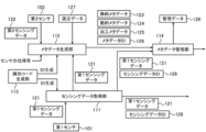
- FIG. 5 schematically illustrates an example of the software configuration of the sensor management unit according to the embodiment.
- FIG. 6 illustrates an example of a processing procedure of matching between a provider of sensing data and a user according to the embodiment.
- FIG. 7A schematically illustrates an example of a provider-side data catalog according to the embodiment.
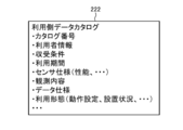
- FIG. 7B schematically illustrates an example of a use-side data catalog according to the embodiment.
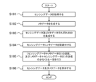
- FIG. 8 illustrates an example of the processing procedure of the sensor management unit according to the embodiment.
- FIG. 9 illustrates an example of a generation process of each metadata by the sensor management unit according to the embodiment.
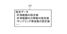
- FIG. 10 schematically illustrates an example of setting data according to the embodiment.
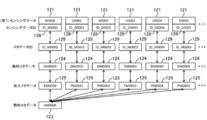
- FIG. 11 schematically illustrates the correspondence between (first) sensing data and various types of metadata according to the embodiment.
- FIG. 12 schematically illustrates an example of management data according to the embodiment.
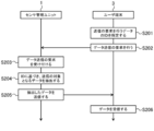
- FIG. 13 illustrates an example of a processing procedure regarding a request for data transmission based on an ID performed between the user terminal and the sensor management unit according to the embodiment.
- the present embodiment an embodiment according to one aspect of the present invention (hereinafter, also referred to as “the present embodiment”) will be described based on the drawings.
- the embodiment described below is merely an illustration of the present invention in all respects. It goes without saying that various improvements and modifications can be made without departing from the scope of the present invention. That is, in the implementation of the present invention, a specific configuration according to the embodiment may be appropriately adopted.
- data appearing in the present embodiment is described in natural language, more specifically, it is specified by a pseudo language, a command, a parameter, a machine language or the like that can be recognized by a computer.
- FIG. 1 schematically illustrates an example of a usage scene of the sensor device 100 according to the present embodiment.
- the sensor device 100 according to the present embodiment is used as a provider that provides sensing data to the user terminal 3 of the user.
- the method of using the sensor device 100 according to the present embodiment is not limited to such an example, and may be appropriately determined according to the embodiment.
- the sensor device 100 includes a first sensor 101 for observing an object, a second sensor 102 for observing a usage pattern of the first sensor 101, and a sensor management unit 1 connected to each sensor (101, 102). Is equipped.
- the first sensor 101 is an example of the “sensor” in the present invention.
- the second sensor 102 may be referred to as a "sub-sensor”.
- the type of each sensor (101, 102) may be selected appropriately according to the observation target.
- the sensor management unit 1 is an information processing apparatus configured to manage sensing data (first sensing data 121 described later) obtained by the first sensor 101. Specifically, the sensor management unit 1 acquires sensing data obtained by observing the target by the first sensor 101. Subsequently, the sensor management unit 1 generates metadata (each metadata 123 to 125 described later) indicating an attribute of the first sensor 101 with respect to the acquired sensing data.
- the content of the metadata is not particularly limited as long as it indicates some information related to sensing data obtained by the first sensor 101 or the first sensor 101, and may be appropriately determined according to the embodiment.
- the metadata may include at least one of dynamic metadata (dynamic metadata 124 described later) and processed metadata (processed metadata 125 described later).
- the dynamic metadata indicates an attribute related to the usage pattern of the first sensor 101 that can change dynamically as time passes.
- the dynamic metadata can be generated, for example, based on sensing data (second sensing data 122 described later) obtained by observing the usage pattern of the first sensor 101 by the second sensor 102.
- the processing metadata is related to the feature amount of the sensing data obtained by the first sensor 101, and can be generated by analyzing the sensing data.
- the sensor management unit 1 detects a sensing data ID (sensing data ID 128 described later) for identifying sensing data obtained by the first sensor 101, and a metadata ID (metadata described later) for identifying metadata. ID 129) is generated.
- the sensing data ID is an example of the "first identification code” in the present invention.
- the metadata ID is an example of the “second identification code” in the present invention.
- the sensor management unit 1 performs at least one of transmission of sensing data to which the metadata ID is assigned and transmission of metadata to which the sensing data ID is assigned to the external device.
- the sensor management unit 1 provides sensing data and metadata to an external device.
- the external device to which sensing data and metadata are provided may not be limited as long as it is another device different from the sensor management unit 1 (sensor device 100), and is appropriately selected according to the embodiment. Good.
- each user terminal 3 is an example of the “external device” in the present invention.
- sensing data and metadata are provided from the sensor device 100 to the user terminal 3 of the user via the network server 2.
- a plurality of sensor devices 100 and a plurality of user terminals 3 are connected to the network server 2 via a network (not shown).
- the type of network may be appropriately selected from, for example, the Internet, a wireless communication network, a mobile communication network, a telephone network, a dedicated network, and the like.
- the network server 2 can match the provision source of the sensing data (sensor device 100) and the use destination (application software etc. executed by the user terminal 3) by a method described later, and can provide the sensing data satisfying the request of the use destination Extract the source of Then, the network server 2 permits the distribution of sensing data between the sensor device 100 in which the matching is established and the user terminal 3. As a result, in the present embodiment, sensing data and metadata are provided from the respective sensor devices 100 to the appropriate user terminal 3.
- the sensor management unit 1 when transmitting the sensing data to the user terminal 3, transmits the metadata ID for identifying the metadata together. Thereby, the user terminal 3 can acquire the metadata corresponding to the received sensing data as needed based on the received metadata ID.
- the sensor management unit 1 when transmitting the metadata to the user terminal 3, the sensor management unit 1 (sensor device 100) according to the present embodiment also transmits a sensing data ID for identifying sensing data. Thereby, the user terminal 3 can acquire the sensing data corresponding to the received metadata as needed based on sensing data ID. Therefore, according to the present embodiment, by transmitting the combination of metadata ID and sensing data or the combination of sensing data ID and metadata to the user terminal 3, the sensing data and metadata in the user terminal 3 concerned The availability of can be secured.
- the data amount of the sensing data ID is smaller than the data amount of the sensing data itself, and the data amount of the metadata ID is smaller than the data amount of the metadata itself. Therefore, the amount of communication in each of the case of transmitting the combination of metadata ID and sensing data and the case of transmitting the combination of sensing data ID and metadata is greater than the amount of communication in the case of transmitting the combination of sensing data and metadata It becomes smaller. Furthermore, the acquisition of each of the sensing data and metadata based on each of the sensing data ID and the metadata ID is not necessarily always performed, and the number of times can be reduced. Therefore, according to the present embodiment, it is possible to reduce the communication amount for transmitting the sensing data and the metadata without impairing the availability of the sensing data and the metadata.
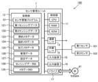
- FIG. 2 schematically illustrates an example of the hardware configuration of the sensor management unit 1 according to the present embodiment.
- the control unit 11, the storage unit 12, the communication interface 13, the external interface 14, the input device 15, the output device 16, and the drive 17 are electrically connected.
- the communication interface and the external interface are described as “communication I / F” and “external I / F”, respectively.
- the control unit 11 includes a hardware processor such as a central processing unit (CPU), a random access memory (RAM), and a read only memory (ROM), and is configured to execute information processing based on a program and various data. Ru.
- the storage unit 12 is an example of “memory”, and is configured of, for example, a hard disk drive, a solid state drive, or the like.
- the storage unit 12 includes a sensor management program 81, first sensing data 121, second sensing data 122, static metadata 123, dynamic metadata 124, processing metadata 125, management data 126, and setting. Data 127, sensing data ID 128, metadata ID 129 and the like are stored.
- the first sensing data 121 is obtained by observing an object with the first sensor 101.
- the second sensing data 122 is obtained by observing the usage pattern of the first sensor 101 by the second sensor 102.
- Each metadata 123 to 125 indicates an attribute of the first sensor 101, and is associated with the first sensing data 121.
- the management data 126 includes information indicating the correspondence between the first sensing data 121 and the metadata 123 to 125 according to the association.
- the setting data 127 includes information indicating the operation setting of the first sensor 101.
- the sensing data ID 128 is used to identify the first sensing data 121.
- the metadata ID 129 is used to identify each of the metadata 123 to 125 associated with the corresponding first sensing data 121.
- the sensor management program 81 includes an instruction to cause the sensor management unit 1 to execute information processing (FIG. 8) for managing the first sensing data 121 and the metadata 123 to 125 described later. Details will be described later.
- the communication interface 13 is, for example, a wired LAN (Local Area Network) module, a wireless LAN module, or the like, and is an interface for performing wired or wireless communication via a network.
- the sensor management unit 1 performs data communication with the network server 2 via the communication interface 13.
- the external interface 14 is, for example, a USB (Universal Serial Bus) port, a dedicated port, or the like, and is an interface for connecting to an external device.
- the type and number of external interfaces 14 may be appropriately selected in accordance with the type and number of external devices to be connected.
- the sensor management unit 1 is connected to each sensor (101, 102) via the external interface 14.
- the type of the first sensor 101 may not be particularly limited, and may be appropriately selected according to the embodiment.
- the first sensor 101 may be, for example, an image sensor, an infrared sensor, a sound sensor, an optical sensor, a pressure sensor, an atmospheric pressure sensor, a temperature sensor, or the like.
- the first sensor 101 may be, for example, an environment sensor, a vital sensor, an on-vehicle sensor, a home security sensor, or the like.
- the environmental sensor is a sensor configured to be able to measure or detect environmental information related to atmospheric pressure, temperature, humidity, sound pressure, sound, ultraviolet light, illuminance, rainfall, gas and the like.
- the vital sensor is a sensor configured to be able to measure or detect vital information such as blood pressure, heart rate, electrocardiogram, body temperature, sleep state (microwave), activity amount, blood glucose level and the like.
- An on-vehicle sensor is a sensor mounted in vehicles, such as an image sensor, a laser sensor, and a sleep (microwave) sensor.
- Home security sensors are related to home security such as image sensors, infrared sensors, activity (voice) sensors, gas (CO2 etc.) sensors, current sensors, smart meters (sensors that measure the amount of power consumed by home appliances, lighting, etc.) It is a sensor configured to measure or detect information.
- the first sensing data 121 obtained by the first sensor 101 is, for example, image data, numerical data, voice data, language data, and the like.
- the first sensor 101 is appropriately disposed so as to be able to observe the state of the object.
- the type of the second sensor 102 may not be particularly limited as long as the usage mode of the first sensor 101 can be observed, and may be appropriately selected according to the embodiment.
- the second sensor 102 may be, for example, a temperature sensor, a GPS sensor, an acceleration sensor, an atmospheric pressure sensor, a geomagnetic sensor, a gyro sensor, or the like.
- the second sensor 102 is appropriately disposed so as to be able to observe the usage pattern of the first sensor 101.
- a temperature sensor is employed as the second sensor 102
- the second sensor 102 can observe the temperature around the first sensor 101. it can.
- the second sensor 102 is attached to a housing (not shown) of the first sensor 101, whereby the attitude of the first sensor 101 is For example, the direction can be observed.
- one first sensor 101 and one second sensor 102 are connected to the sensor management unit 1.
- the number of each of the first sensor 101 and the second sensor 102 connected to the sensor management unit 1 may not be limited to one, and may be two or more.
- a plurality of first sensors 101 may be connected to the sensor management unit 1.
- a plurality of second sensors 102 may be used.
- the number of sensors (101, 102) connected to the sensor management unit 1 may be appropriately determined according to the embodiment.
- the input device 15 is, for example, a device for performing input such as a mouse and a keyboard.
- the output device 16 is, for example, a device for outputting a display, a speaker or the like. A user who is a provider of sensing data can operate the sensor management unit 1 using the input device 15 and the output device 16.
- the drive 17 is, for example, a CD drive, a DVD drive, or the like, and is a drive device for reading a program stored in the storage medium 91.
- the type of drive 17 may be appropriately selected according to the type of storage medium 91.
- the sensor management program 81 may be stored in the storage medium 91.
- the storage medium 91 stores information such as a program by an electric, magnetic, optical, mechanical or chemical action so that information such as a computer or other device or program recorded on a machine can be read.
- the sensor management unit 1 may obtain the sensor management program 81 from the storage medium 91.
- a disc-type storage medium such as a CD or a DVD is illustrated.
- the type of storage medium 91 is not limited to the disc type, and may be other than the disc type.
- a storage medium other than the disk type for example, a semiconductor memory such as a flash memory can be mentioned.
- the control unit 11 may include a plurality of hardware processors.
- the hardware processor may be configured by a microprocessor, a field-programmable gate array (FPGA), a digital signal processor (DSP), and the like.
- the storage unit 12 may be configured by a RAM and a ROM included in the control unit 11.
- the input device 15 and the output device 16 may be omitted.
- the sensor management unit 1 may be connected to each sensor (101, 102) via the communication interface 13, not the external interface 14. In this case, the external interface 14 may be omitted.
- the sensor management unit 1 is comprised by one information processing apparatus in FIG. 2, you may be comprised by two or more information processing apparatuses.
- the hardware configuration of each information processing device may or may not match.
- the sensor management unit 1 may be a general-purpose desktop PC (Personal Computer), a tablet PC, a smartphone, a mobile phone other than a smartphone, a programmable logic controller (PLC), etc., in addition to an information processing device designed specifically for services. Good.
- PLC programmable logic controller
- FIG. 3 schematically illustrates an example of the hardware configuration of the network server 2 according to the present embodiment.
- the network server 2 is a computer to which the control unit 21, the storage unit 22, and the communication interface 23 are electrically connected.
- the communication interface is described as "communication I / F".
- control unit 21 includes a hardware processor such as a CPU, a RAM, and a ROM, and is configured to execute various information processing based on programs and data.
- the storage unit 22 includes, for example, a hard disk drive, a solid state drive, and the like, and stores the program 82, the providing side data catalog 221, the using side data catalog 222, and the like.
- the program 82 includes an instruction to cause the network server 2 to execute information processing (FIG. 11) for matching a provider and a use destination described later.
- the provider data catalog 221 is prepared for each provider and includes information indicating sensing data (first sensing data 121) that can be provided by the sensor (first sensor 101) of each sensor device 100.
- the use-side data catalog 222 is prepared for each use destination, and includes information indicating sensing data desired by the user.
- the provider data catalog 221 and the user data catalog 222 are used for matching of a provider and a user. Details will be described later.
- the communication interface 23, like the communication interface 13, is an interface for performing communication via a network.
- the communication interface 23 is, for example, a wired LAN module, a wireless LAN module, or the like.
- the network server 2 performs data communication with each sensor device 100 and each user terminal 3 via the communication interface 23.
- control unit 21 may include a plurality of hardware processors.
- the hardware processor may be configured by a microprocessor, an FPGA or the like.
- the storage unit 22 may be configured by a RAM and a ROM included in the control unit 21.
- the network server 2 may further include an input device and an output device as a user interface.
- the network server 2 may be a general-purpose server device, a general-purpose PC, or the like, in addition to an information processing device designed for service only.
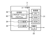
- FIG. 4 schematically illustrates an example of the hardware configuration of the user terminal 3 according to the present embodiment.
- the user terminal 3 is a computer in which the control unit 31, the storage unit 32, the communication interface 33, the input device 34, and the output device 35 are electrically connected.
- the communication interface is described as “communication I / F” as in FIGS. 2 and 3.
- the control unit 31 includes a CPU that is a hardware processor, a RAM, a ROM, and the like, similarly to the control units (11, 22), and is configured to execute various information processing based on programs and data.
- the storage unit 32 includes, for example, a hard disk drive, a solid state drive, and the like, and stores the application program 83 and the like.
- the application program 83 includes an instruction to cause the control unit 31 to execute predetermined information processing, and uses sensing data (first sensing data 121) provided from each user terminal 3.
- the type of application program 83 may not be particularly limited, and may be appropriately selected according to the embodiment.
- the communication interface 33 is an interface for performing communication via a network, similarly to the above-described communication interfaces (13, 23).
- the communication interface 33 is, for example, a wired LAN module, a wireless LAN module, or the like.
- the user terminal 3 performs data communication with the network server 2 via the communication interface 33.
- the input device 34 is, for example, a device for performing an input such as a mouse and a keyboard as the input device 15 described above.
- the output device 35 is, for example, a device for outputting a display, a speaker, and the like, as in the case of the output device 16.
- the user of the sensing data can operate the user terminal 3 using the input device 34 and the output device 35.
- control unit 31 may include a plurality of hardware processors.
- the hardware processor may be configured by a microprocessor, an FPGA, or the like.
- the storage unit 32 may be configured by a RAM and a ROM included in the control unit 31.
- the user terminal 3 may be a general-purpose desktop PC, a tablet PC, a smartphone, a mobile phone other than a smartphone, or the like, in addition to an information processing apparatus designed specifically for service.
- FIG. 5 schematically illustrates an example of the software configuration of the sensor management unit 1 according to the present embodiment.
- the control unit 11 of the sensor management unit 1 deploys the sensor management program 81 stored in the storage unit 12 in the RAM. Then, the control unit 11 causes the CPU to interpret the sensor management program 81 expanded in the RAM, and executes information processing based on the interpretation while controlling each component.
- the sensor management unit 1 includes, as software modules, a sensing data acquisition unit 111, a metadata generation unit 112, an identification code generation unit 113, a metadata management unit 114, and communication.
- a computer including the unit 115 and the catalog change unit 116 is configured.
- the sensing data acquisition unit 111 acquires the first sensing data 121 obtained by observing the target by the first sensor 101.
- the metadata generation unit 112 generates metadata indicating an attribute of the first sensor 101 with respect to the acquired first sensing data 121.
- the metadata generation unit 112 generates three types of metadata, static metadata 123, dynamic metadata 124, and processed metadata 125, as metadata indicating the attributes of the first sensor 101. .
- the static metadata 123 is configured to indicate an attribute related to the specification of the first sensor 101 that does not change over time. That is, the information held as the static metadata 123 basically relates to an attribute whose value is always constant and which is not likely to change depending on the usage form.
- the dynamic metadata 124 is an attribute of the first sensor 101 at the time when the first sensing data 121 is obtained, and indicates an attribute related to the usage pattern of the first sensor 101 that can dynamically change with the passage of time. Configured as.
- the attribute relating to the usage form of the first sensor 101 indicated by the dynamic metadata 124 is, for example, an attribute relating to the operation setting of the first sensor 101, an attribute relating to the installation situation of the first sensor 101, and the like.
- the information held as the dynamic metadata 124 is not limited to a constant value, but relates to an attribute that may change depending on the usage form. That is, the dynamic metadata 124 is an object to confirm (or track) whether or not the use form of the first sensor 101 has changed in order to determine, for example, the reliability, validity, etc. of the sensing data. Indicates information on the attribute to be acquired.
- the metadata generation unit 112 generates the dynamic metadata 124 based on the second sensing data 122 and the like obtained by observing the usage pattern of the first sensor 101 by the second sensor 102. .
- the processing metadata 125 relates to the feature amount of the acquired first sensing data 121.
- the metadata generation unit 112 generates the processed metadata 125 by analyzing the acquired first sensing data 121.
- the identification code generation unit 113 generates a sensing data ID 128 for identifying the first sensing data 121, and a metadata ID 129 for identifying each of the metadata 123 to 125.
- the metadata management unit 114 manages the generated metadata 123 to 125 in association with the first sensing data 121.
- the communication unit 115 performs at least one of transmission of the first sensing data 121 to which the metadata ID 129 is assigned and transmission of each of the metadata 123 to 125 to which the sensing data ID 128 is assigned to the external device such as the user terminal 3. .
- the catalog changing unit 116 changes the content of the provider data catalog 221 stored in the network server 2 in accordance with the change of the usage pattern of the first sensor 101.
- each software module of the sensor management unit 1 will be described in detail in an operation example described later.
- an example in which each software module of the sensor management unit 1 is realized by a general-purpose CPU is described.
- the method of implementing each software module may not be limited to such an example.
- Some or all of the software modules may be implemented by one or more dedicated processors. Further, regarding the software configuration of the sensor management unit 1, omission, replacement, and addition of software modules may be appropriately performed according to the embodiment.
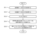
- FIG. 6 shows an example of a processing procedure of matching by the network server 2 according to the present embodiment.
- the processing procedure of the matching described below is only an example, and each processing may be changed as much as possible.
- steps may be omitted, replaced, or added as appropriate, according to the embodiment.
- Step S11 and S12 First, in step S ⁇ b> 11, the control unit 21 of the network server 2 acquires a providing-side data catalog 221 indicating sensing data that can be provided by each sensor device 100. In the next step S12, the control unit 21 acquires the use-side data catalog 222 indicating the sensing data desired by the user.
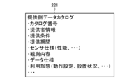
- FIG. 7A schematically illustrates an example of the provider-side data catalog 221 according to the present embodiment.
- the provider-side data catalog 221 according to the present embodiment includes information such as catalog number, provider information, provision condition, provision period, sensor specification, observation content, data specification, usage form and the like.
- the control unit 21 may appropriately generate the provider data catalog 221 by acquiring various information registered in the provider data catalog 221.
- the catalog number is a number for identifying the provider data catalog 221.
- the control unit 21 may appropriately generate an arbitrary number not used for the other providing side data catalog 221, and set the generated number as the catalog number.
- provider information is information for specifying the provider of sensing data, For example, a provider's name (personal name or organization name), a provider's contact point etc. may be included.
- the information on the provision conditions defines the conditions under which the provision of sensing data is permitted.
- the provision conditions include, for example, usage of sensing data (commercial / non-commercial / no restriction), scope of provision (providing to third party / not permitted), access right (replication impossible / replication possible / modification possible / processable) Conditions such as presence or absence of personal information, presence or absence of anonymous processing information, and payment types of expenses for use of sensing data may be included.
- Information on the provision period defines a period for which provision of sensing data is permitted (for example, the start date and end date of the provision).
- the control unit 21 receives the input or designation from the provider via each sensor device 100 or other information processing apparatus when generating the provider-side data catalog 221, thereby providing provider information, provision conditions, and provision. You may acquire each information of a period.
- the information on the sensor specification indicates an attribute on the specification of the first sensor 101, and may include, for example, information on the performance of the first sensor 101, device information, information on an initial installation condition, and the like.
- the information related to the performance of the first sensor 101 may include, for example, information such as the sensitivity limit of the first sensor 101, the dynamic range, the settable range of the spatial resolution, and the settable range of the sampling frequency.
- the device information of the first sensor 101 may include, for example, information such as the name of the first sensor 101, the description of the first sensor 101, and the like.
- the information on the initial installation condition of the first sensor 101 may include, for example, information such as a proper noun of the installation place of the first sensor 101.
- the information about the observation content indicates the attribute of the observation performed using the first sensor 101, and, for example, the name of the observation (for example, environmental observation), the explanation about the observation, and the name of the target for observation (for example, A establishment) ,
- the description about the observation object, the name of the observation index (for example, temperature, humidity, etc.), the explanation about the observation index, etc. may be included.
- the data specification information indicates an attribute related to the specification of the first sensing data 121 obtained by the first sensor 101.
- the name of the observed value (temperature value, maximum power consumption value, etc.) indicated by the first sensing data 121, It may include information such as the explanation of the observation value and the unit of the observation value.
- the control unit 21 When the control unit 21 generates the provider-side data catalog 221, the sensor specification, the observation content, and the data specification are obtained from the static metadata 123 associated with the first sensor 101 or the first sensing data 121 of each sensor device 100. Of each information may be acquired.
- the information on the usage mode indicates an attribute of the first sensor 101 that may change according to the usage mode, and may include, for example, information on operation setting of the first sensor 101 and information on the installation status of the first sensor 101 .
- the information on the operation setting of the first sensor 101 may include, for example, information such as a set value of the measurement range of the first sensor 101, a set value of resolution of the measurement range, and a set value of the sampling frequency.
- the information on the installation state of the first sensor 101 may include, for example, information such as the installation angle of the first sensor 101, the temperature around the first sensor 101, and the distance between the first sensor 101 and the observation target. Good.
- the control unit 21 may obtain information on the usage form from the dynamic metadata 124 associated with each sensor device 100 or the first sensing data 121.
- FIG. 7B schematically illustrates an example of the use-side data catalog 222 according to the present embodiment.
- the use-side data catalog 222 according to the present embodiment includes information such as catalog number, user information, collection condition, use period, sensor specification, observation content, data specification, use form and the like.
- the control unit 21 receives input or designation from the user via each user terminal 3 or other information processing apparatus, and acquires various information to be registered in the use-side data catalog 222.
- the data catalog 222 may be generated as appropriate.
- the catalog number is the same as the catalog number of the provider data catalog 221.
- each information of user information, collection condition, use period, sensor specification, observation content, data specification, and use form is the provider information of the above-mentioned provider data catalog 221, provision condition, provision period, sensor specification, observation It corresponds to each information of content, data specification, and usage form.
- the user information is information for identifying the user of the sensing data.
- the information on receipt conditions defines conditions for accepting provision of sensing data.
- the information on the usage period defines a period (for example, start date and time and usage end date and time of use) for which provision of sensing data is desired or desired to be provided.
- the information on the sensor specification indicates an attribute on the specification of the sensor for which it is desired to provide sensing data.
- the information on the content of observation indicates the attribute of the observation for which it is desired to provide sensing data.
- the data specification information indicates an attribute related to the specification of sensing data desired to be provided.
- the information on the use form indicates an attribute that may change according to the use form of the sensor for which provision of sensing data is desired.
- each information of user information, collection condition, usage period, sensor specification, observation content, data specification, and usage form are the provider information of the above-mentioned provider data catalog 221, provision condition, provision period, sensor It may be the same as the information of the specification, the observation content, the data specification, and the usage form.
- the generation of the provider data catalog 221 and the user data catalog 222 may not be performed by the network server 2.
- the provider data catalog 221 may be generated by each sensor device 100 or another information processor of the provider.
- the use-side data catalog 222 may be generated by each user terminal 3 or another information processing apparatus of the user.
- the control unit 21 may acquire the provider data catalog 221 from each sensor device 100 or another information processor of the provider via the network.
- the control unit 21 may acquire the use-side data catalog 222 from each user terminal 3 or another information processing apparatus of the user via the network.
- Steps S13 and S14 In the next step S13, the control unit 21 matches the provision source with the use destination by collating each item of the provision side data catalog 221 with each item of the use side data catalog 222. In the next step S14, based on the result of the matching, the sensor device 100 (first sensor 101) capable of providing sensing data (first sensing data 121) satisfying the user's request is extracted.
- the control unit 21 provides the provision condition of the provider data catalog 221, the provision period, the sensor specification, the observation content, the data specification, the collection condition of each item of the usage form and the usage data catalog 222, and uses Each item of a period, a sensor specification, an observation content, a data specification, and a utilization form is collated, and it is determined whether each item is suitable. As a result of the determination, when all or part of the items match, the control unit 21 senses the sensor device 100 corresponding to the provider data catalog 221 to satisfy the user request corresponding to the user data catalog 222. Extract data as available.
- control unit 21 determines that the sensor device 100 corresponding to the provider-side data catalog 221 can not provide sensing data satisfying the request of the user corresponding to the user-side data catalog 222 Do.
- the method of matching may not be limited to such an example, and may be appropriately determined according to the embodiment.
- Step S15 the control unit 21 permits the distribution of the sensing data (first sensing data 121) from the extracted sensor device 100 to the target user terminal 3.
- the control unit 21 transmits, to the extracted sensor device 100, a data flow permission instruction indicating that transmission of sensing data to the target user terminal 3 is permitted.
- each sensor device 100 transmits the first sensing data 121 obtained by observing the target with the first sensor 101 to the target user terminal 3 specified by the data flow permission command.
- the control unit 21 ends the matching process according to the present operation example.
- FIG. 8 illustrates an example of a processing procedure for managing the first sensing data 121 by the sensor management unit 1 according to the present embodiment.
- FIG. 9 schematically illustrates an example of a management process of the first sensing data 121 by the sensor management unit 1 according to the present embodiment.
- the processing procedure described below is an example of the “sensor management method” in the present invention. However, the processing procedure described below is merely an example, and each processing may be changed as much as possible. In addition, according to the embodiment, steps may be omitted, replaced, or added as appropriate, according to the embodiment.
- Step S101 First, in step S101, the control unit 11 of the sensor management unit 1 operates as the sensing data acquisition unit 111, and acquires the first sensing data 121 obtained by observing the target by the first sensor 101.
- the sensor management unit 1 holds setting data 127 indicating the operation setting of the first sensor 101. Therefore, the control unit 11 refers to the setting data 127 to specify the operation setting of the first sensor 101.
- FIG. 10 schematically illustrates an example of the setting data 127 according to the present embodiment.
- the setting data 127 includes, for example, information such as a setting value of the measurement range, a setting value of the resolution of the measurement range, and a setting value of the sampling frequency as information indicating the operation setting of the first sensor 101.
- the control unit 11 controls the operation of the first sensor 101 based on these pieces of information.
- control unit 11 controls the operation of the first sensor 101 based on the setting value of the measurement range indicated by the setting data 127 and the setting value of the resolution. Then, the control unit 11 sets a setting value indicated by the setting data 127 as a sampling frequency, and performs sampling processing of a signal output from the first sensor 101. Thereby, the control unit 11 can acquire the first sensing data 121.
- the method of acquiring the first sensing data 121 may not be limited to such an example, and may be appropriately determined according to the embodiment.
- control and sampling processing of the first sensor 101 may be performed by another information processing apparatus.
- the control unit 11 may acquire the first sensing data 121 from the other information processing apparatus.
- the control unit 11 proceeds to the next step S102.
- the first sensing data 121 may be configured to be time-series data having a certain time width, or may be configured to indicate an observation result of a temporary point.
- the configuration of the first sensing data 121 may not be particularly limited, and may be appropriately determined according to the embodiment.
- Step S102 In the next step S102, the control unit 11 operates as the metadata generation unit 112, and the static metadata 123, the dynamic metadata 124, and the processing metadata are applied to the first sensing data 121 acquired in step S101. Generate 125. After generating the metadata 123 to 125, the control unit 11 advances the process to the next step S103.
- the static metadata 123 is configured to indicate an attribute related to the specification of the first sensor 101 that does not change with time. As long as it is configured as such, the contents of the static metadata 123 may be appropriately determined according to the embodiment.
- the static metadata 123 may include, for example, an attribute related to the performance of the first sensor 101, an attribute related to device information of the first sensor 101, an attribute related to an initial installation condition of the first sensor 101, and the like.
- the control unit 11 obtains information corresponding to each item from the first information sensor 101 or another information processing apparatus that holds information on the specification of the first sensor 101, and generates static metadata 123 based on the obtained information. You may
- Dynamic metadata Dynamic metadata 124 is an attribute of the first sensor 101 at the time when the first sensing data 121 is obtained, and the first sensor 101 can change dynamically with the passage of time. It is configured to indicate the attribute regarding the usage form As long as it is configured as such, the contents of the dynamic metadata 124 may be appropriately determined according to the embodiment.
- the attribute relating to the usage form of the first sensor 101 indicated by the dynamic metadata 124 may include, for example, an attribute relating to the operation setting of the first sensor 101, an attribute relating to the installation state of the first sensor 101, and the like.
- the attributes related to the operation setting of the first sensor 101 are, for example, a set value of the measurement range, a set value of the resolution of the measurement range, a set value of the sampling frequency, and the like.
- information on the operation setting of the first sensor 101 is stored in the storage unit 12 as setting data 127. Therefore, the control unit 11 may acquire the information related to the operation setting of the first sensor 101 by referring to the setting data 127, and may generate the dynamic metadata 124 based on the acquired information.
- the attribute regarding the installation condition of the first sensor 101 is, for example, an installation angle of the first sensor 101, a temperature around the first sensor 101, a distance between the first sensor 101 and an observation target, and the like.
- the use form of the first sensor 101 is monitored by the second sensor 102 connected to the sensor management unit 1. Therefore, the control unit 11 may generate the dynamic metadata 124 based on the second sensing data 122 obtained by observing the usage pattern of the first sensor 101 by the second sensor 102.
- the second sensing data 122 obtained by the second sensor 102 is the temperature around the first sensor 101 Show. Therefore, even if the control unit 11 acquires the second sensing data 122 and generates data indicating the temperature around the first sensor 101 as the dynamic metadata 124 based on the acquired second sensing data 122. Good.
- the control unit 11 may acquire the second sensing data 122 and generate data indicating the installation angle of the first sensor 101 as the dynamic metadata 124 based on the acquired second sensing data 122. .
- the configuration of the dynamic metadata 124 may not be limited to such an example, and may be appropriately determined according to the embodiment. For example, at least one of the information on the attribute related to the operation setting of the first sensor 101 and the information on the attribute related to the installation status may be omitted. Also, the dynamic metadata 124 may include information on attributes regarding the usage form of the first sensor 101 other than the information on the attribute regarding the operation setting of the first sensor 101 and the information about the attribute regarding the installation status.
- control unit 11 may generate the dynamic metadata 124 regardless of the setting data 127 and the second sensing data 122.
- the control unit 11 may generate the dynamic metadata 124 based on the first sensing data 121.
- the control unit 11 analyzes the first sensing data 121 to specify the distance between the first sensor 101 and the observation target, and the specified distance May be generated as dynamic metadata 124.
- the dynamic metadata 124 is configured to indicate an attribute related to the usage pattern of the first sensor 101 at the time when the first sensing data 121 is obtained. Therefore, it is preferable that the point in time of the usage pattern of the first sensor 101 indicated by the dynamic metadata 124 coincide with the point in time when the first sensing data 121 is obtained. However, this “when the first sensing data 121 is obtained” may not be exact.
- the time of the usage pattern of the first sensor 101 indicated by the dynamic metadata 124 and the time of obtaining the first sensing data 121 may not completely coincide, and the dynamic metadata 124 They may be offset from each other as long as they do not have a fatal impact on usage.
- the point of time of usage of the first sensor 101 indicated by the dynamic metadata 124 and the point of time when the first sensing data 121 are obtained deviate from each other to such an extent that the utilization of the dynamic metadata 124 is not adversely affected. Is also included in the "point when the first sensing data 121 is obtained".
- control unit 11 may acquire the setting data 127 and the second sensing data 122 used to generate the dynamic metadata 124 at the same timing as the first sensing data 121, or the first sensing data 121. And may be acquired at different timings.
- the method of acquiring the second sensing data 122 may be the same as the method of acquiring the first sensing data 121 in step S101.
- the processed metadata 125 is configured to indicate the feature amount of the first sensing data 121 acquired in step S101. As long as it is configured as such, the content of the processing metadata 125 may be appropriately determined according to the embodiment.
- the control unit 11 can generate processing metadata 125 by executing a predetermined analysis process on the first sensing data 121 acquired in step S101.
- the type of predetermined analysis processing when generating the processing metadata 125 may not be particularly limited, and may be appropriately selected according to the embodiment.
- the predetermined analysis processing may be, for example, labeling processing, arithmetic processing for deriving a variation, arithmetic processing for deriving a vector value, conversion processing, cleansing processing, filtering processing, and the like.
- the conversion process is an arithmetic process for aligning units, scales, and the like. Cleansing processing is arithmetic processing for removing data other than the true value of sensing data.
- the filtering process is an arithmetic process for applying a filter such as an LPF, an HPF, or a BPF to sensing data.
- the type of the feature amount obtained as the processing metadata 125 by the analysis processing is not particularly limited as long as it indicates the feature of the first sensing data 121 acquired in step S101, and according to the embodiment May be selected appropriately.
- the feature amount obtained as the processing metadata 125 may be, for example, a label, a change amount, a vector value, an outlier, or the like.
- the contents of the dynamic metadata 124 and the processing metadata 125 depend on the timing and content of acquiring the first sensing data 121. Therefore, the control unit 11 newly generates the dynamic metadata 124 and the processing metadata 125 with respect to the acquired first sensing data 121 each time the processing of steps S101 and S102 is repeated.
- the content of the static metadata 123 does not depend on the first sensing data 121. Therefore, after creating the static metadata 123 once, the control unit 11 does not have to newly create the static metadata 123 for the same first sensor 101. That is, the control unit 11 may generate the static metadata 123 only when this step S102 is first executed.
- the timing of generating the static metadata 123 may be different from the timing of executing the present step S102.
- the control unit 11 connects, for example, the first sensor 101 to the sensor management unit 1 before executing step S101, and sets the static meta to the sensor management unit 1 at the time of initial setting for registering the first sensor 101. Data 123 may be generated.
- Step S103 In the next step S103, the control unit 11 operates as the identification code generation unit 113, and generates a sensing data ID 128 for identifying the first sensing data 121 acquired in step S101. Further, the control unit 11 generates a metadata ID 129 for identifying each of the metadata 123 to 125 generated in step S102.
- one sensing data ID 128 is assigned to one piece of first sensing data 121 acquired in step S101.
- one metadata ID 129 is assigned to one combination of static metadata 123, dynamic metadata 124, and processing metadata 125 corresponding to the first sensing data 121.
- the correspondence between the first sensing data 121 and the sensing data ID 128 and the correspondence between each of the metadata 123 to 125 and the metadata ID 129 may not be limited to such an example. It may be determined accordingly.
- the sensing data ID 128 and the metadata ID 129 may be configured by symbols such as letters, numbers, and codes.
- the control unit 11 does not assign to the other first sensing data 121, that is, an arbitrary symbol string different from the symbol string of the sensing data ID 128 paired with the other first sensing data 121. You may generate suitably as new sensing data ID128. Then, the control unit 11 may pair the generated new sensing data ID 128 with the first sensing data 121 acquired in step S101.
- control unit 11 does not assign to the other combinations of the metadata 123 to 125, that is, the symbol string of the metadata ID 129 paired with the other combinations of the metadata 123 to 125 A different arbitrary symbol string may be generated as new metadata ID 129 as appropriate. Then, the control unit 11 may pair the generated new metadata ID 129 with the combination of the metadata 123 to 125 generated in step S102.
- the sensing data ID 128 and the metadata ID 129 may be configured by a universal unique identifier (UUID) or a global unique identifier (GUID).
- UUID universal unique identifier
- GUID global unique identifier
- the control unit 11 may appropriately acquire the UUID or GUID from an external server apparatus or the like, and assign the acquired UUID or GUID to the sensing data ID 128 and the metadata ID 129, respectively. Thereby, the control unit 11 can generate each of the sensing data ID 128 and the metadata ID 129 by UUID or GUID.
- each of the sensing data ID 128 and the metadata ID 129 may not be limited to each example as described above, and may be appropriately determined according to the embodiment.
- the sensing data ID 128 is preferably configured to have a smaller amount of data than the first sensing data 121.
- the metadata ID 129 is preferably configured to have a smaller amount of data than the sum of the metadata 123 to 125.
- Step S104 In the next step S104, the control unit 11 operates as the metadata management unit 114, and associates each of the metadata 123 to 125 generated in step S102 with the first sensing data 121 acquired in step S101.
- control unit 11 associates each metadata 123 to 125 with the first sensing data 121 using the sensing data ID 128 and the metadata ID 129. Then, the control unit 11 updates the content of the management data 126 by adding information indicating the result of the association to the management data 126. Thus, the control unit 11 manages the correspondence between each of the metadata 123 to 125 and the first sensing data 121.
- FIG. 11 schematically illustrates the correspondence between the first sensing data 121 and each of the metadata 123 to 125.
- FIG. 12 schematically illustrates an example of the management data 126 according to the present embodiment. 11 and 12, the dynamic metadata 124 and the processing metadata 125 are newly generated each time the first sensing data 121 is acquired, whereas the static metadata 123 is one time. An example will not be newly generated after being generated.
- the first sensing data 121 such as "D0000” is acquired, and accordingly, the sensing data ID 128 such as “ID_D0000” is each first sensing data 121. It is tied to.
- dynamic metadata 124 such as “DM 0000” and processed metadata 125 such as “PM 0000” are generated for each first sensing data 121 by repeatedly executing step S 102.
- common static metadata 123 “SM0000” is generated for each first sensing data 121.
- a metadata ID 129 such as “ID_M0000” is associated with a combination of static metadata 123, dynamic metadata 124, and processing metadata 125 corresponding to each first sensing data 121.
- control unit 11 can associate the combination of the metadata 123 to 125 with the corresponding first sensing data 121 by associating the corresponding sensing data ID 128 with the metadata ID 129.
- the static metadata 123 “SM0000”, the dynamic metadata 124 “DM000n”, and the processing metadata 125 are linked by linking the sensing data ID 128 “ID_D000n” and the metadata ID 129 “ID_M000n”.
- the combination of “PM 000 n” is associated with the first sensing data 121 “D 000 n” (n is 0 to 5).
- the control unit 11 stores, as management data 126, information indicating the correspondence by this association.
- each record (row data) of the management data 126 indicates the correspondence by each association.
- each record of the management data 126 has a field for storing each of the sensing data ID 128 and the metadata ID 129.
- the control unit 11 stores the associated first sensing data 121 and each ID (128, 129) of each of the metadata 123 to 125 in each field of the new record to manage information indicating the result of the association as management data. It can be added to 126.
- the management data 126 is expressed in a table format.
- the data format of the management data 126 may not be limited to such a table format, and may be appropriately selected according to the embodiment.
- control unit 11 can associate each of the metadata 123 to 125 with the first sensing data 121. Further, the correspondence relationship by the association can be managed by the management data 126. After these processes are completed, the control unit 11 advances the process to the next step S105.
- Step S105 In the next step S105, the control unit 11 operates as the communication unit 115, and transmits the first sensing data 121 to which the metadata ID 129 is assigned to the user terminal 3 permitted to be distributed by the network server 2, and sensing At least one of the transmission of the metadata 123 to 125 assigned the data ID 128 is performed.
- the control unit 11 transmits either the first sensing data 121 to which the metadata ID 129 is assigned or the transmission of each of the metadata 123 to 125 to which the sensing data ID 128 is assigned. It is preferable to do only one or the other. At this time, the control unit 11 transmits the first sensing data 121 attached with the metadata ID 129 in the first period, and each meta added with the sensing data ID 128 in the second period different from the first period. Data 123 to 125 may be transmitted. When the transmission of the first sensing data 121 to which the metadata ID 129 is assigned or the metadata 123 to 125 to which the sensing data ID 128 is assigned is completed, the control unit 11 advances the process to the next step S106.
- control part 11 may transmit metadata ID129 and the 1st sensing data 121 using a different communication port in this step S105.
- control unit 11 may transmit the sensing data ID 128 and the metadata 123 to 125 using different communication ports.
- the second control unit 11 is different from the first communication port.
- the metadata ID 129 or the sensing data ID 128 may be transmitted to the target user terminal 3 by the communication port.
- the communication port is an endpoint for data communication.
- TCP Transmission Control Protocol
- UDP User Datagram Protocol
- the control unit 11 can perform data communication with the user terminal 3 at different communication ports.
- the port for transmitting each data (121, 123 to 125) and each ID (128, 129) may not be limited to such an example, and may be identical.
- control unit 11 transmits the first sensing data 121 to which the metadata ID 129 is assigned or the metadata 123 to 125 to which the sensing data ID 128 is assigned to the symmetrical user terminal 3 via the network server 2. Alternatively, it may be directly transmitted to the target user terminal 3 without passing through the network server 2.
- the network server 2 targets the first sensing data 121 to which the metadata ID 129 received from each sensor management unit 1 is added or the metadata 123 to 125 to which the sensing data ID 128 is added.
- Step S106 In the next step S106, the control unit 11 stores the first sensing data 121 and the metadata 123 to 125 in the storage unit 12.
- the timing at which the storage process of step S106 is performed may not be limited to such an example, and may be appropriately determined according to the embodiment.
- the control unit 11 may store the first sensing data 121 in the storage unit 12 at an arbitrary timing.
- the control unit 11 may store the metadata 123 to 125 in the storage unit 12 at an arbitrary timing after generating the metadata 123 to 125.
- control unit 11 ends the series of processes according to the present operation example.
- the application program 83 can use the first sensing data 121 or the metadata 123 to 125.
- the control unit 11 may execute the process from step S101 again. That is, the control unit 11 may repeatedly execute the series of processes of steps S101 to S106 until the observation of the object by the first sensor 101 is completed.
- the processing procedure for sensor management according to the present operation example may be changed as much as possible.
- the series of processes of steps S101 to S104 and S106 and the process of step S105 may be performed at different timings.
- the process of generating the sensing data ID 128 and the process of generating the metadata ID 129 may be performed in different steps.
- the control unit 11 may execute the process of association in step S104.
- control unit 11 when the contents of the dynamic metadata 124 are changed while repeatedly executing the processes of steps S101 and S102, the control unit 11 operates as the catalog changing unit 116, and the control unit 11 A command may be sent to the network server 2 to change the content of the usage pattern to conform to the content of the generated dynamic metadata 124. As a result, information on the latest usage form of the first sensor 101 can be reflected on the provider-side data catalog 221.
- the method of updating the contents of the usage form of the provider-side data catalog 221 may not be limited to such an example.
- the network server 2 does not wait for such a command, and the dynamic metadata 124 received from each sensor management unit 1 Information on the usage form of the target provider data catalog 221 may be changed based on the content.
- control unit 11 may receive a change in the operation setting of the first sensor 101 from the user via the network server 2, each user terminal 3, or another information processing apparatus.
- the information on the use form of the use-side data catalog 222 may be used to designate the change content of the operation setting of the first sensor 101. That is, the control unit 11 may receive, as a command instructing change of the operation setting of the first sensor 101, information related to the use form of the use-side data catalog 222.
- control unit 11 may correct the content of the setting data 127 to the content specified by the user, and change the operation setting of the first sensor 101 when acquiring the first sensing data 121.
- the operation setting of the first sensor 101 can be changed according to the request of each user.
- FIG. 13 illustrates an example of a processing procedure regarding a request for data transmission based on the sensing data ID 128 or the metadata ID 129 performed between the user terminal 3 and the sensor management unit 1 according to the present embodiment.
- the processing procedure of the data transmission request described below is only an example, and each processing may be changed as much as possible.
- steps may be omitted, replaced, or added as appropriate, according to the embodiment.
- Step S201 the control unit 31 of the user terminal 3 specifies an ID of data to be a request for transmission.
- the control unit 31 requests the target sensor management unit 1 (sensor device 100) to transmit data based on the ID specified in step S201.
- the first sensing data 121 to which the metadata ID 129 is assigned is transmitted from the sensor management unit 1 to the user terminal 3 in the step S105.
- the user terminal 3 holds the first sensing data 121 but does not hold the metadata 123 to 125 corresponding to the first sensing data 121. Therefore, in step S201, even if the control unit 31 designates the metadata ID 129 assigned to the first sensing data 121 received from the sensor management unit 1 as the ID of the data to be requested for transmission, as necessary. Good.
- the control unit 31 requests the target sensor management unit 1 to transmit the metadata 123 to 125 corresponding to the target first sensing data 121 based on the metadata ID 129. It is also good.
- step S105 the control unit 31 designates, as necessary, the sensing data ID 128 assigned to each of the metadata 123 to 125 received from the sensor management unit 1 as an ID of data to be transmitted. It is also good.
- step S202 the control unit 31 requests the target sensor management unit 1 to transmit the first sensing data 121 corresponding to each target metadata 123 to 125 based on the sensing data ID 128. It is also good.
- the specification of the ID of the data to be requested for transmission may be performed manually by the user or may be performed automatically by information processing in the application program 83 or the like.
- the control unit 31 outputs a list of each ID (128, 129) to the output device 35 such as a display, and transmits the data via the input device 34.
- the specification of the ID of the data to be requested may be accepted.
- step S203 the control unit 11 of the sensor management unit 1 receives a request for data transmission based on the ID from the user terminal 3.
- the control unit 11 receives the request for transmission of the target first sensing data 121 or each of the metadata 123 to 125 based on the sensing data ID 128 or the metadata ID 129, the process proceeds to the next step S204.
- step S204 the control unit 11 extracts, from the storage unit 12, the first sensing data 121 or each metadata 123 to 125 to be transmitted, based on the received sensing data ID 128 or metadata ID 129. Then, in the next step S205, the control unit 11 operates as the communication unit 115, and transmits the extracted first sensing data 121 or the metadata 123 to 125 to the user terminal 3 of the request source.
- the control unit 11 receives from the user terminal 3 a request for transmission of the first sensing data 121 in accordance with the designation of the sensing data ID 128, the first sensing data 121 specified by the designated sensing data ID 128 is received. Are sent to the user terminal 3.
- the control unit 11 receives from the user terminal 3 a request for transmission of each of the metadata 123 to 125 accompanied by the specification of the metadata ID 129, each of the metadata 123 to 125 specified by the specified metadata ID 129 Send 125 to the user terminal 3.
- Step S206 the control unit 31 of the user terminal 3 receives the first sensing data 121 or the metadata 123 to 125.
- the user terminal 3 acquires the metadata 123 to 125 corresponding to the first sensing data 121 received earlier, or the first sensing data 121 corresponding to each metadata 123 to 125 received earlier can do.
- the user terminal 3 acquires each metadata 123 to 125 corresponding to the first sensing data 121 received earlier, based on the received metadata ID 129, as necessary. Can.
- both sensing data IDs 128 for identifying the corresponding first sensing data 121 are transmitted. Be done.
- the user terminal 3 acquires the first sensing data 121 corresponding to each of the metadata 123 to 125 received earlier, as necessary, based on the received sensing data ID 128. Can. Therefore, according to the present embodiment, the availability of the first sensing data 121 and the metadata 123 to 125 in the user terminal 3 can be secured.
- the sensing data ID 128 can be configured to have a smaller amount of data than the first sensing data 121 itself, and the metadata ID 129 is configured to have a smaller amount of data than the total of each of the metadata 123 to 125 It is possible. Therefore, the communication amount in each of the case of transmitting the combination of the metadata ID 129 and the first sensing data 121 and the case of transmitting the combination of the sensing data ID 128 and each of the metadata 123 to 125 is the first sensing data 121 and each metadata It is smaller than the amount of communication in the case of transmitting the combination of 123 to 125.
- the communication amount for transmitting the first sensing data 121 and the metadata 123 to 125 is reduced without impairing the availability of the first sensing data 121 and the metadata 123 to 125. be able to.
- the metadata according to the present embodiment includes at least one of the dynamic metadata 124 and the processing metadata 125.
- the dynamic metadata 124 indicates attributes related to the usage of the sensor that can change dynamically as time passes.
- the processing metadata 125 indicates information on the feature amount of the first sensing data 121. Therefore, if the timing to obtain the first sensing data 121 is different, the contents of the generated dynamic metadata 124 and the processing metadata 125 may be different.
- the dynamic metadata 124 and the processing metadata 125 be generated each time the first sensing data 121 is obtained by the step S102.
- the data amount of metadata including the dynamic metadata 124 and the processing metadata 125 increases. .
- the communication amount required to transmit the first sensing data 121 and the metadata is increased.
- the present embodiment even in the present case where the data amount of metadata tends to increase, by using the sensing data ID 128 and the metadata ID 129, the first sensing data 121 and the metadata can be obtained. It is possible to reduce the amount of communication required for transmission. That is, the present technology for suppressing the communication amount required for transmitting the first sensing data 121 and metadata using the sensing data ID 128 and the metadata ID 129 includes at least one of the dynamic metadata 124 and the processing metadata 125. In this case, it is more effective to increase the amount of metadata data.
- the sensor device 100 (sensor management unit 1) is connected to the network server 2 via the network, and the first sensing data 121 is sent to the user terminal 3 of each user according to the result of matching by the network server 2.
- the method of providing the first sensing data 121 may not be limited to such an example, and may be appropriately determined according to the embodiment.
- the network server 2 may be omitted, and the sensor device 100 may provide the first sensing data 121 and the metadata 123 to 125 to each user terminal 3 in response to a request from each user terminal 3.
- step S102 of the above embodiment the control unit 11 of the sensor management unit 1 can generate dynamic metadata 124 based on the second sensing data 122 obtained by the second sensor 102.
- the method of generating the dynamic metadata 124 may not be limited to such an example, and the control unit 11 may generate the dynamic metadata 124 not based on the second sensing data 122. . In this case, the second sensor 102 may be omitted.
- the metadata generated in step S 102 may include static metadata 123, dynamic metadata 124, and processing metadata 125. However, at least one of the static metadata 123, the dynamic metadata 124, and the processing metadata 125 may be omitted. Also, the metadata may include other types of metadata.
- one metadata ID 129 is assigned to one combination of the static metadata 123, the dynamic metadata 124, and the processing metadata 125 corresponding to the first sensing data 121.
- the method of assigning the metadata ID may not be limited to such an example, and may be appropriately determined according to the embodiment.
- metadata IDs may be individually assigned to the metadata 123 to 125, respectively.
- the control unit 11 of the sensor management unit 1 transmits the first sensing data 121 to which the metadata ID 129 is assigned and the transmissions of the metadata 123 to 125 to which the sensing data ID 128 is assigned by the process of step S105.
- the transmission content of the sensor management unit 1 may not be limited to such an example.
- the sensor management unit 1 may have a mode for collectively transmitting the first sensing data 121 and the metadata 123 to 125, in addition to the mode for executing the process of step S105.
- the first sensing data 121 acquired in step S101 and the dynamic metadata 124 and processing metadata 125 generated in step S102 are accumulated in the storage unit 12 of the sensor management unit 1. Therefore, the sensor management unit 1 may discard the first sensing data 121, the dynamic metadata 124, and the processing metadata 125 beyond the predetermined storage period from the storage unit 12.
- each user terminal 3 transmits the first sensing data 121 or the first sensing data 121 to each sensor management unit 1 (sensor device 100) based on the sensing data ID 128 or the metadata ID 129 by the processes of steps S201 to S206.
- the data transmission of each metadata 123 to 125 is requested.
- the storage destinations of the first sensing data 121 and the metadata 123 to 125 may not be limited to each sensor management unit 1, and may be appropriately selected according to the embodiment.
- each sensor management unit 1 may transfer the first sensing data 121 and the metadata 123 to 125 to an external storage device such as a NAS (Network Attached Storage). In this case, each user terminal 3 may request the external storage device to transmit the data.
- NAS Network Attached Storage
- the sensor management unit 1 in order to change the contents of the provider data catalog 221 based on the dynamic metadata 124, the sensor management unit 1 includes the catalog change unit 117 as a software module. However, the catalog changing unit 117 may be omitted.
- the sensing data ID 128 and the metadata ID 129 are used to associate the first sensing data 121 with each of the metadata 123 to 125.
- the method of associating the first sensing data 121 with each of the metadata 123 to 125 may not be limited to such an example, and may be appropriately determined according to the embodiment.
- the first sensing data 121 may be associated with each of the metadata 123 to 125 regardless of the sensing data ID 128 and the metadata ID 129.
- control unit 11 transmits all of the static metadata 123, the dynamic metadata 124, and the processing metadata 125 at one time in step S105.
- transmission of at least part of the static metadata 123, the dynamic metadata 124, and the processing metadata 125 may be omitted in step S105.
- the control unit 11 may omit the transmission of the static metadata 123 after transmitting the static metadata 123 once.
- the sensor device 100 (the sensor management unit 1) transmits the second sensing data 122 to the external device such as the user terminal 3 together with the first sensing data 121 or in place of the first sensing data 121. May be provided.
- the sensor management unit 1 may generate the sensing data ID 128 and the metadata 123 to 125 for the second sensing data 122. That is, the second sensing data 122 may be treated as the "sensing data" of the present invention together with or instead of the first sensing data 121.
- the static metadata 123 may change according to the use form It relates to non-sex attributes.
- the changing / non-changing period may be limited to the period for providing sensing data. That is, as a result of the matching by the network server 2, the attribute of the first sensor 101 that may change within the period in which the first sensing data 121 is provided from the sensor management unit 1 to the target user terminal 3 is a dynamic meta It is treated as an object of the data 124, and the attribute of the first sensor 101 which is not possible may be treated as an object of the static metadata 123. In this case, the attribute indicated by the static metadata 123 may change (change) outside the period of providing the first sensing data 121.
- ... sensor management unit 11: control unit, 12: storage unit, 13: communication interface, 14: external interface, 15: input device, 16: output device, 17 ... drive, 100 ... sensor device, 101: first sensor (sensor) 102: second sensor 111 ... sensing data acquisition unit, 112 ... metadata generation unit, 113: identification code generation unit 114: metadata management unit 115: Communication unit 116: Catalog change unit 121 ... first sensing data (sensing data), 122 ... second sensing data, 123 ... static metadata, 124 ... dynamic metadata, 125 ... processing metadata, 126 ... management data, 127 ... setting data, 128 ... sensing data ID (first identification code), 129 ... metadata ID (second identification code), 2 ...
- Network server 21: control unit, 22: storage unit, 23: communication interface, 221 ... provider-side data catalog, 222 ... user side data catalog, 3 ...
- User terminal 31: control unit, 32: storage unit, 33: communication interface, 34 ... input device, 35 ... output device, 81: Sensor management program, 82 ... program, 83 ... program, 91: Storage medium
Landscapes
- Engineering & Computer Science (AREA)
- Computer Networks & Wireless Communication (AREA)
- Computing Systems (AREA)
- Signal Processing (AREA)
- Physics & Mathematics (AREA)
- General Physics & Mathematics (AREA)
- Health & Medical Sciences (AREA)
- General Health & Medical Sciences (AREA)
- Medical Informatics (AREA)
- Arrangements For Transmission Of Measured Signals (AREA)
- Testing Or Calibration Of Command Recording Devices (AREA)
- Selective Calling Equipment (AREA)
Abstract
Une unité de gestion de capteur selon un aspect de la présente invention comprend : une unité d'acquisition de données de détection qui acquiert des données de détection obtenues par l'observation d'un objet au moyen d'un capteur ; une unité de génération de métadonnées qui génère des métadonnées indiquant un attribut du capteur par rapport aux données de détection acquises ; une unité de génération de code d'identification qui génère un premier code d'identification pour identifier les données de détection et un second code d'identification pour identifier les métadonnées ; et une unité de communication qui transmet, à un dispositif externe, les données de détection auxquelles a été attribué le second code d'identification et/ou les métadonnées auxquelles a été attribué le premier code d'identification.
Priority Applications (3)
| Application Number | Priority Date | Filing Date | Title |
|---|---|---|---|
| EP18844774.2A EP3667252B1 (fr) | 2017-08-09 | 2018-07-17 | Unité de gestion de capteur, dispositif de capteur, procédé de gestion de capteur, et programme de gestion de capteur |
| CN201880049779.2A CN110959102B (zh) | 2017-08-09 | 2018-07-17 | 传感器管理单元、传感器装置、传感器管理方法以及存储介质 |
| US16/632,893 US11563810B2 (en) | 2017-08-09 | 2018-07-17 | Sensor management unit, sensor device, sensor management method, and sensor management program |
Applications Claiming Priority (4)
| Application Number | Priority Date | Filing Date | Title |
|---|---|---|---|
| JP2017-153899 | 2017-08-09 | ||
| JP2017153899 | 2017-08-09 | ||
| JP2017-230052 | 2017-11-30 | ||
| JP2017230052A JP6421866B1 (ja) | 2017-08-09 | 2017-11-30 | センサ管理ユニット、センサ装置、センサ管理方法及びセンサ管理プログラム |
Publications (1)
| Publication Number | Publication Date |
|---|---|
| WO2019031161A1 true WO2019031161A1 (fr) | 2019-02-14 |
Family
ID=64269166
Family Applications (1)
| Application Number | Title | Priority Date | Filing Date |
|---|---|---|---|
| PCT/JP2018/026629 Ceased WO2019031161A1 (fr) | 2017-08-09 | 2018-07-17 | Unité de gestion de capteur, dispositif de capteur, procédé de gestion de capteur, et programme de gestion de capteur |
Country Status (5)
| Country | Link |
|---|---|
| US (1) | US11563810B2 (fr) |
| EP (1) | EP3667252B1 (fr) |
| JP (1) | JP6421866B1 (fr) |
| CN (1) | CN110959102B (fr) |
| WO (1) | WO2019031161A1 (fr) |
Families Citing this family (3)
| Publication number | Priority date | Publication date | Assignee | Title |
|---|---|---|---|---|
| JPWO2021090356A1 (fr) * | 2019-11-05 | 2021-05-14 | ||
| WO2021166260A1 (fr) * | 2020-02-21 | 2021-08-26 | 日本電信電話株式会社 | Système de collecte de données, et procédé de collecte de données |
| EP4186216B1 (fr) * | 2020-08-27 | 2025-05-21 | Siemens Aktiengesellschaft | Gestion centralisée des flux de données pour le déploiement des passerelles distribuées |
Citations (4)
| Publication number | Priority date | Publication date | Assignee | Title |
|---|---|---|---|---|
| JP2005242534A (ja) | 2004-02-25 | 2005-09-08 | Foundation For The Promotion Of Industrial Science | 情報提供システムおよびデータ生成装置 |
| JP5445722B1 (ja) | 2012-09-12 | 2014-03-19 | オムロン株式会社 | データフロー制御指令発生装置およびセンサ管理装置 |
| JP2017084134A (ja) * | 2015-10-28 | 2017-05-18 | オムロン株式会社 | データ流通管理システム |
| JP2017111501A (ja) * | 2015-12-14 | 2017-06-22 | オムロン株式会社 | データフロー制御装置およびデータフロー制御方法 |
Family Cites Families (9)
| Publication number | Priority date | Publication date | Assignee | Title |
|---|---|---|---|---|
| KR101263380B1 (ko) * | 2009-11-11 | 2013-05-23 | 한국전자통신연구원 | 논리적인 센서 네트워크 지원 시스템 및 방법 |
| US8832017B2 (en) * | 2010-05-01 | 2014-09-09 | Bruce W. Adams | System and method to define, validate and extract data for predictive models |
| ES2491491B1 (es) * | 2013-03-05 | 2015-06-16 | Vodafone España, S.A.U. | Método para asociar de manera anónima mediciones de un dispositivo de monitorización sanitaria con un ID de usuario |
| CN105408898B (zh) | 2013-03-15 | 2019-05-28 | 弗兰克公司 | 测量数据的自动记录和图形生成 |
| US20150381737A1 (en) * | 2014-06-30 | 2015-12-31 | Davra Networks Limited | Gateway device and a gateway system for an internet-of-things environment |
| WO2017011327A1 (fr) * | 2015-07-10 | 2017-01-19 | Whether or Knot LLC | Systèmes et procédés de distribution électronique de données |
| EP3345071B1 (fr) * | 2015-09-04 | 2020-07-15 | Spacemetric AB | Téléchargement intelligent de données de détection dans des systèmes de détection à distance |
| JP6406336B2 (ja) * | 2016-11-14 | 2018-10-17 | オムロン株式会社 | センサ開通テストシステム、センサ開通テスト管理端末、センサ、センサ開通テスト方法及びプログラム |
| CN108667884B (zh) * | 2017-04-01 | 2021-01-05 | 华为技术有限公司 | 镜像分发方法、镜像获取方法及装置 |
-
2017
- 2017-11-30 JP JP2017230052A patent/JP6421866B1/ja active Active
-
2018
- 2018-07-17 US US16/632,893 patent/US11563810B2/en active Active
- 2018-07-17 WO PCT/JP2018/026629 patent/WO2019031161A1/fr not_active Ceased
- 2018-07-17 EP EP18844774.2A patent/EP3667252B1/fr active Active
- 2018-07-17 CN CN201880049779.2A patent/CN110959102B/zh active Active
Patent Citations (4)
| Publication number | Priority date | Publication date | Assignee | Title |
|---|---|---|---|---|
| JP2005242534A (ja) | 2004-02-25 | 2005-09-08 | Foundation For The Promotion Of Industrial Science | 情報提供システムおよびデータ生成装置 |
| JP5445722B1 (ja) | 2012-09-12 | 2014-03-19 | オムロン株式会社 | データフロー制御指令発生装置およびセンサ管理装置 |
| JP2017084134A (ja) * | 2015-10-28 | 2017-05-18 | オムロン株式会社 | データ流通管理システム |
| JP2017111501A (ja) * | 2015-12-14 | 2017-06-22 | オムロン株式会社 | データフロー制御装置およびデータフロー制御方法 |
Non-Patent Citations (1)
| Title |
|---|
| See also references of EP3667252A4 |
Also Published As
| Publication number | Publication date |
|---|---|
| JP2019032801A (ja) | 2019-02-28 |
| US20210160322A1 (en) | 2021-05-27 |
| US11563810B2 (en) | 2023-01-24 |
| CN110959102B (zh) | 2021-09-28 |
| EP3667252B1 (fr) | 2023-01-25 |
| EP3667252A1 (fr) | 2020-06-17 |
| EP3667252A4 (fr) | 2020-12-23 |
| CN110959102A (zh) | 2020-04-03 |
| JP6421866B1 (ja) | 2018-11-14 |
Similar Documents
| Publication | Publication Date | Title |
|---|---|---|
| JP6451820B1 (ja) | センサ管理ユニット、センサ装置、センサ管理方法及びセンサ管理プログラム | |
| US9967330B2 (en) | Virtual resource bank for localized and self determined allocation of resources | |
| KR102317535B1 (ko) | 소프트웨어 개발 키트로 데이터 추적을 구현하는 방법 및 시스템 | |
| CN112583882A (zh) | 用于管理边缘环境中的遥测数据的方法、系统、制品和装置 | |
| US11030143B2 (en) | System for sharing content between electronic devices, and content sharing method for electronic device | |
| KR101940823B1 (ko) | 모바일 컴퓨팅 장치 센서를 이용한 프라이빗 스페이스의 맵 생성 | |
| US10754869B2 (en) | Managing data format of data received from devices in an internet of things network | |
| CN110891005A (zh) | Iot设备的控制方法、云服务器及iot设备控制系统 | |
| JP2021502735A (ja) | ゲートウェイ管理コンソールにアクセスする方法、システム、およびプログラム | |
| JP2021502624A (ja) | ゲートウェイ管理コンソールにアクセスするためのコンピュータ処理方法、装置、システム、およびプログラム | |
| JP2021502732A (ja) | ゲートウェイ管理コンソールにアクセスするためのコンピュータ処理方法、装置、システム、およびプログラム | |
| JP5806167B2 (ja) | サービス提供システム、サービス計算機、及び端末 | |
| JP6421866B1 (ja) | センサ管理ユニット、センサ装置、センサ管理方法及びセンサ管理プログラム | |
| JP6969362B2 (ja) | センサ管理装置とその方法およびプログラム、マッチング装置とその方法およびプログラム | |
| JP7056289B2 (ja) | 管理システム、端末装置、管理装置、管理方法、およびプログラム | |
| US20190129907A1 (en) | Data transfer system, data transfer apparatus, data transfer method, and computer-readable recording medium | |
| CN109819026B (zh) | 用于传输信息的方法及装置 | |
| US10482397B2 (en) | Managing identifiers | |
| JP2018055457A (ja) | データ収集システム、収集装置、情報収集プログラム、サーバ装置およびサーバプログラム | |
| US9715544B2 (en) | Online location sharing through an internet service search engine | |
| WO2020021758A1 (fr) | Dispositif de traitement d'informations, dispositif de génération de données d'image, système de traitement d'informations, procédé de traitement d'informations, et programme | |
| CN116980495A (zh) | 一种数据转换方法、装置、计算机设备、介质及产品 | |
| CN115695365A (zh) | 消息传递方法、装置、电子设备及存储介质 | |
| CN112256654B (zh) | 一种文档共享方法及装置 | |
| JP2018055478A (ja) | 評価値提供プログラム、装置、及び方法 |
Legal Events
| Date | Code | Title | Description |
|---|---|---|---|
| 121 | Ep: the epo has been informed by wipo that ep was designated in this application |
Ref document number: 18844774 Country of ref document: EP Kind code of ref document: A1 |
|
| NENP | Non-entry into the national phase |
Ref country code: DE |
|
| ENP | Entry into the national phase |
Ref document number: 2018844774 Country of ref document: EP Effective date: 20200309 |