WO2019031208A1 - リチウムイオン電池用電極材料、リチウムイオンキャパシタ用電極材料、電極、電池、キャパシタ、電気機器、リチウムイオン電池用電極材料の製造方法、およびリチウムイオンキャパシタ用電極材料の製造方法 - Google Patents
リチウムイオン電池用電極材料、リチウムイオンキャパシタ用電極材料、電極、電池、キャパシタ、電気機器、リチウムイオン電池用電極材料の製造方法、およびリチウムイオンキャパシタ用電極材料の製造方法 Download PDFInfo
- Publication number
- WO2019031208A1 WO2019031208A1 PCT/JP2018/027432 JP2018027432W WO2019031208A1 WO 2019031208 A1 WO2019031208 A1 WO 2019031208A1 JP 2018027432 W JP2018027432 W JP 2018027432W WO 2019031208 A1 WO2019031208 A1 WO 2019031208A1
- Authority
- WO
- WIPO (PCT)
- Prior art keywords
- lithium ion
- electrode
- component
- sulfur
- electrode material
- Prior art date
- Legal status (The legal status is an assumption and is not a legal conclusion. Google has not performed a legal analysis and makes no representation as to the accuracy of the status listed.)
- Ceased
Links
Images
Classifications
-
- H—ELECTRICITY
- H01—ELECTRIC ELEMENTS
- H01M—PROCESSES OR MEANS, e.g. BATTERIES, FOR THE DIRECT CONVERSION OF CHEMICAL ENERGY INTO ELECTRICAL ENERGY
- H01M4/00—Electrodes
- H01M4/02—Electrodes composed of, or comprising, active material
- H01M4/36—Selection of substances as active materials, active masses, active liquids
- H01M4/362—Composites
- H01M4/366—Composites as layered products
-
- H—ELECTRICITY
- H01—ELECTRIC ELEMENTS
- H01M—PROCESSES OR MEANS, e.g. BATTERIES, FOR THE DIRECT CONVERSION OF CHEMICAL ENERGY INTO ELECTRICAL ENERGY
- H01M10/00—Secondary cells; Manufacture thereof
- H01M10/05—Accumulators with non-aqueous electrolyte
- H01M10/052—Li-accumulators
- H01M10/0525—Rocking-chair batteries, i.e. batteries with lithium insertion or intercalation in both electrodes; Lithium-ion batteries
-
- H—ELECTRICITY
- H01—ELECTRIC ELEMENTS
- H01G—CAPACITORS; CAPACITORS, RECTIFIERS, DETECTORS, SWITCHING DEVICES, LIGHT-SENSITIVE OR TEMPERATURE-SENSITIVE DEVICES OF THE ELECTROLYTIC TYPE
- H01G11/00—Hybrid capacitors, i.e. capacitors having different positive and negative electrodes; Electric double-layer [EDL] capacitors; Processes for the manufacture thereof or of parts thereof
- H01G11/04—Hybrid capacitors
- H01G11/06—Hybrid capacitors with one of the electrodes allowing ions to be reversibly doped thereinto, e.g. lithium ion capacitors [LIC]
-
- H—ELECTRICITY
- H01—ELECTRIC ELEMENTS
- H01G—CAPACITORS; CAPACITORS, RECTIFIERS, DETECTORS, SWITCHING DEVICES, LIGHT-SENSITIVE OR TEMPERATURE-SENSITIVE DEVICES OF THE ELECTROLYTIC TYPE
- H01G11/00—Hybrid capacitors, i.e. capacitors having different positive and negative electrodes; Electric double-layer [EDL] capacitors; Processes for the manufacture thereof or of parts thereof
- H01G11/22—Electrodes
- H01G11/30—Electrodes characterised by their material
- H01G11/32—Carbon-based
-
- H—ELECTRICITY
- H01—ELECTRIC ELEMENTS
- H01G—CAPACITORS; CAPACITORS, RECTIFIERS, DETECTORS, SWITCHING DEVICES, LIGHT-SENSITIVE OR TEMPERATURE-SENSITIVE DEVICES OF THE ELECTROLYTIC TYPE
- H01G11/00—Hybrid capacitors, i.e. capacitors having different positive and negative electrodes; Electric double-layer [EDL] capacitors; Processes for the manufacture thereof or of parts thereof
- H01G11/22—Electrodes
- H01G11/30—Electrodes characterised by their material
- H01G11/50—Electrodes characterised by their material specially adapted for lithium-ion capacitors, e.g. for lithium-doping or for intercalation
-
- H—ELECTRICITY
- H01—ELECTRIC ELEMENTS
- H01G—CAPACITORS; CAPACITORS, RECTIFIERS, DETECTORS, SWITCHING DEVICES, LIGHT-SENSITIVE OR TEMPERATURE-SENSITIVE DEVICES OF THE ELECTROLYTIC TYPE
- H01G11/00—Hybrid capacitors, i.e. capacitors having different positive and negative electrodes; Electric double-layer [EDL] capacitors; Processes for the manufacture thereof or of parts thereof
- H01G11/54—Electrolytes
-
- H—ELECTRICITY
- H01—ELECTRIC ELEMENTS
- H01G—CAPACITORS; CAPACITORS, RECTIFIERS, DETECTORS, SWITCHING DEVICES, LIGHT-SENSITIVE OR TEMPERATURE-SENSITIVE DEVICES OF THE ELECTROLYTIC TYPE
- H01G11/00—Hybrid capacitors, i.e. capacitors having different positive and negative electrodes; Electric double-layer [EDL] capacitors; Processes for the manufacture thereof or of parts thereof
- H01G11/84—Processes for the manufacture of hybrid or EDL capacitors, or components thereof
- H01G11/86—Processes for the manufacture of hybrid or EDL capacitors, or components thereof specially adapted for electrodes
-
- H—ELECTRICITY
- H01—ELECTRIC ELEMENTS
- H01M—PROCESSES OR MEANS, e.g. BATTERIES, FOR THE DIRECT CONVERSION OF CHEMICAL ENERGY INTO ELECTRICAL ENERGY
- H01M10/00—Secondary cells; Manufacture thereof
- H01M10/05—Accumulators with non-aqueous electrolyte
- H01M10/052—Li-accumulators
-
- H—ELECTRICITY
- H01—ELECTRIC ELEMENTS
- H01M—PROCESSES OR MEANS, e.g. BATTERIES, FOR THE DIRECT CONVERSION OF CHEMICAL ENERGY INTO ELECTRICAL ENERGY
- H01M4/00—Electrodes
- H01M4/02—Electrodes composed of, or comprising, active material
- H01M4/13—Electrodes for accumulators with non-aqueous electrolyte, e.g. for lithium-accumulators; Processes of manufacture thereof
-
- H—ELECTRICITY
- H01—ELECTRIC ELEMENTS
- H01M—PROCESSES OR MEANS, e.g. BATTERIES, FOR THE DIRECT CONVERSION OF CHEMICAL ENERGY INTO ELECTRICAL ENERGY
- H01M4/00—Electrodes
- H01M4/02—Electrodes composed of, or comprising, active material
- H01M4/13—Electrodes for accumulators with non-aqueous electrolyte, e.g. for lithium-accumulators; Processes of manufacture thereof
- H01M4/137—Electrodes based on electro-active polymers
-
- H—ELECTRICITY
- H01—ELECTRIC ELEMENTS
- H01M—PROCESSES OR MEANS, e.g. BATTERIES, FOR THE DIRECT CONVERSION OF CHEMICAL ENERGY INTO ELECTRICAL ENERGY
- H01M4/00—Electrodes
- H01M4/02—Electrodes composed of, or comprising, active material
- H01M4/13—Electrodes for accumulators with non-aqueous electrolyte, e.g. for lithium-accumulators; Processes of manufacture thereof
- H01M4/139—Processes of manufacture
-
- H—ELECTRICITY
- H01—ELECTRIC ELEMENTS
- H01M—PROCESSES OR MEANS, e.g. BATTERIES, FOR THE DIRECT CONVERSION OF CHEMICAL ENERGY INTO ELECTRICAL ENERGY
- H01M4/00—Electrodes
- H01M4/02—Electrodes composed of, or comprising, active material
- H01M4/13—Electrodes for accumulators with non-aqueous electrolyte, e.g. for lithium-accumulators; Processes of manufacture thereof
- H01M4/139—Processes of manufacture
- H01M4/1399—Processes of manufacture of electrodes based on electro-active polymers
-
- H—ELECTRICITY
- H01—ELECTRIC ELEMENTS
- H01M—PROCESSES OR MEANS, e.g. BATTERIES, FOR THE DIRECT CONVERSION OF CHEMICAL ENERGY INTO ELECTRICAL ENERGY
- H01M4/00—Electrodes
- H01M4/02—Electrodes composed of, or comprising, active material
- H01M4/36—Selection of substances as active materials, active masses, active liquids
- H01M4/38—Selection of substances as active materials, active masses, active liquids of elements or alloys
-
- H—ELECTRICITY
- H01—ELECTRIC ELEMENTS
- H01M—PROCESSES OR MEANS, e.g. BATTERIES, FOR THE DIRECT CONVERSION OF CHEMICAL ENERGY INTO ELECTRICAL ENERGY
- H01M4/00—Electrodes
- H01M4/02—Electrodes composed of, or comprising, active material
- H01M4/36—Selection of substances as active materials, active masses, active liquids
- H01M4/38—Selection of substances as active materials, active masses, active liquids of elements or alloys
- H01M4/381—Alkaline or alkaline earth metals elements
- H01M4/382—Lithium
-
- H—ELECTRICITY
- H01—ELECTRIC ELEMENTS
- H01M—PROCESSES OR MEANS, e.g. BATTERIES, FOR THE DIRECT CONVERSION OF CHEMICAL ENERGY INTO ELECTRICAL ENERGY
- H01M4/00—Electrodes
- H01M4/02—Electrodes composed of, or comprising, active material
- H01M4/36—Selection of substances as active materials, active masses, active liquids
- H01M4/60—Selection of substances as active materials, active masses, active liquids of organic compounds
-
- H—ELECTRICITY
- H01—ELECTRIC ELEMENTS
- H01M—PROCESSES OR MEANS, e.g. BATTERIES, FOR THE DIRECT CONVERSION OF CHEMICAL ENERGY INTO ELECTRICAL ENERGY
- H01M4/00—Electrodes
- H01M4/02—Electrodes composed of, or comprising, active material
- H01M4/36—Selection of substances as active materials, active masses, active liquids
- H01M4/60—Selection of substances as active materials, active masses, active liquids of organic compounds
- H01M4/602—Polymers
-
- H—ELECTRICITY
- H01—ELECTRIC ELEMENTS
- H01M—PROCESSES OR MEANS, e.g. BATTERIES, FOR THE DIRECT CONVERSION OF CHEMICAL ENERGY INTO ELECTRICAL ENERGY
- H01M4/00—Electrodes
- H01M4/02—Electrodes composed of, or comprising, active material
- H01M4/36—Selection of substances as active materials, active masses, active liquids
- H01M4/60—Selection of substances as active materials, active masses, active liquids of organic compounds
- H01M4/602—Polymers
- H01M4/604—Polymers containing aliphatic main chain polymers
-
- H—ELECTRICITY
- H01—ELECTRIC ELEMENTS
- H01M—PROCESSES OR MEANS, e.g. BATTERIES, FOR THE DIRECT CONVERSION OF CHEMICAL ENERGY INTO ELECTRICAL ENERGY
- H01M4/00—Electrodes
- H01M4/02—Electrodes composed of, or comprising, active material
- H01M4/36—Selection of substances as active materials, active masses, active liquids
- H01M4/60—Selection of substances as active materials, active masses, active liquids of organic compounds
- H01M4/602—Polymers
- H01M4/606—Polymers containing aromatic main chain polymers
- H01M4/608—Polymers containing aromatic main chain polymers containing heterocyclic rings
-
- H—ELECTRICITY
- H01—ELECTRIC ELEMENTS
- H01M—PROCESSES OR MEANS, e.g. BATTERIES, FOR THE DIRECT CONVERSION OF CHEMICAL ENERGY INTO ELECTRICAL ENERGY
- H01M4/00—Electrodes
- H01M4/02—Electrodes composed of, or comprising, active material
- H01M4/62—Selection of inactive substances as ingredients for active masses, e.g. binders, fillers
-
- H—ELECTRICITY
- H01—ELECTRIC ELEMENTS
- H01M—PROCESSES OR MEANS, e.g. BATTERIES, FOR THE DIRECT CONVERSION OF CHEMICAL ENERGY INTO ELECTRICAL ENERGY
- H01M4/00—Electrodes
- H01M4/02—Electrodes composed of, or comprising, active material
- H01M4/62—Selection of inactive substances as ingredients for active masses, e.g. binders, fillers
- H01M4/621—Binders
-
- H—ELECTRICITY
- H01—ELECTRIC ELEMENTS
- H01M—PROCESSES OR MEANS, e.g. BATTERIES, FOR THE DIRECT CONVERSION OF CHEMICAL ENERGY INTO ELECTRICAL ENERGY
- H01M4/00—Electrodes
- H01M4/02—Electrodes composed of, or comprising, active material
- H01M4/62—Selection of inactive substances as ingredients for active masses, e.g. binders, fillers
- H01M4/621—Binders
- H01M4/622—Binders being polymers
-
- H—ELECTRICITY
- H01—ELECTRIC ELEMENTS
- H01M—PROCESSES OR MEANS, e.g. BATTERIES, FOR THE DIRECT CONVERSION OF CHEMICAL ENERGY INTO ELECTRICAL ENERGY
- H01M4/00—Electrodes
- H01M4/02—Electrodes composed of, or comprising, active material
- H01M4/62—Selection of inactive substances as ingredients for active masses, e.g. binders, fillers
- H01M4/624—Electric conductive fillers
-
- H—ELECTRICITY
- H01—ELECTRIC ELEMENTS
- H01M—PROCESSES OR MEANS, e.g. BATTERIES, FOR THE DIRECT CONVERSION OF CHEMICAL ENERGY INTO ELECTRICAL ENERGY
- H01M4/00—Electrodes
- H01M4/02—Electrodes composed of, or comprising, active material
- H01M2004/021—Physical characteristics, e.g. porosity, surface area
-
- H—ELECTRICITY
- H01—ELECTRIC ELEMENTS
- H01M—PROCESSES OR MEANS, e.g. BATTERIES, FOR THE DIRECT CONVERSION OF CHEMICAL ENERGY INTO ELECTRICAL ENERGY
- H01M2220/00—Batteries for particular applications
- H01M2220/20—Batteries in motive systems, e.g. vehicle, ship, plane
-
- H—ELECTRICITY
- H01—ELECTRIC ELEMENTS
- H01M—PROCESSES OR MEANS, e.g. BATTERIES, FOR THE DIRECT CONVERSION OF CHEMICAL ENERGY INTO ELECTRICAL ENERGY
- H01M2220/00—Batteries for particular applications
- H01M2220/30—Batteries in portable systems, e.g. mobile phone, laptop
-
- H—ELECTRICITY
- H01—ELECTRIC ELEMENTS
- H01M—PROCESSES OR MEANS, e.g. BATTERIES, FOR THE DIRECT CONVERSION OF CHEMICAL ENERGY INTO ELECTRICAL ENERGY
- H01M2300/00—Electrolytes
- H01M2300/0017—Non-aqueous electrolytes
- H01M2300/0025—Organic electrolyte
-
- Y—GENERAL TAGGING OF NEW TECHNOLOGICAL DEVELOPMENTS; GENERAL TAGGING OF CROSS-SECTIONAL TECHNOLOGIES SPANNING OVER SEVERAL SECTIONS OF THE IPC; TECHNICAL SUBJECTS COVERED BY FORMER USPC CROSS-REFERENCE ART COLLECTIONS [XRACs] AND DIGESTS
- Y02—TECHNOLOGIES OR APPLICATIONS FOR MITIGATION OR ADAPTATION AGAINST CLIMATE CHANGE
- Y02E—REDUCTION OF GREENHOUSE GAS [GHG] EMISSIONS, RELATED TO ENERGY GENERATION, TRANSMISSION OR DISTRIBUTION
- Y02E60/00—Enabling technologies; Technologies with a potential or indirect contribution to GHG emissions mitigation
- Y02E60/10—Energy storage using batteries
-
- Y—GENERAL TAGGING OF NEW TECHNOLOGICAL DEVELOPMENTS; GENERAL TAGGING OF CROSS-SECTIONAL TECHNOLOGIES SPANNING OVER SEVERAL SECTIONS OF THE IPC; TECHNICAL SUBJECTS COVERED BY FORMER USPC CROSS-REFERENCE ART COLLECTIONS [XRACs] AND DIGESTS
- Y02—TECHNOLOGIES OR APPLICATIONS FOR MITIGATION OR ADAPTATION AGAINST CLIMATE CHANGE
- Y02E—REDUCTION OF GREENHOUSE GAS [GHG] EMISSIONS, RELATED TO ENERGY GENERATION, TRANSMISSION OR DISTRIBUTION
- Y02E60/00—Enabling technologies; Technologies with a potential or indirect contribution to GHG emissions mitigation
- Y02E60/13—Energy storage using capacitors
-
- Y—GENERAL TAGGING OF NEW TECHNOLOGICAL DEVELOPMENTS; GENERAL TAGGING OF CROSS-SECTIONAL TECHNOLOGIES SPANNING OVER SEVERAL SECTIONS OF THE IPC; TECHNICAL SUBJECTS COVERED BY FORMER USPC CROSS-REFERENCE ART COLLECTIONS [XRACs] AND DIGESTS
- Y02—TECHNOLOGIES OR APPLICATIONS FOR MITIGATION OR ADAPTATION AGAINST CLIMATE CHANGE
- Y02T—CLIMATE CHANGE MITIGATION TECHNOLOGIES RELATED TO TRANSPORTATION
- Y02T10/00—Road transport of goods or passengers
- Y02T10/60—Other road transportation technologies with climate change mitigation effect
- Y02T10/70—Energy storage systems for electromobility, e.g. batteries
Definitions
- the present invention relates to an electrode material for a lithium ion battery, an electrode material for a lithium ion capacitor, an electrode, a battery, a capacitor, an electric device, a method for producing an electrode material for a lithium ion battery, and a method for producing an electrode material for a lithium ion capacitor.
- alkaline secondary batteries such as nickel-cadmium (Ni-Cd) batteries and nickel-hydrogen (Ni-MH) batteries have mainly been used as secondary batteries, but the above-mentioned miniaturization and high energy density From the demand, the use of lithium ion batteries tends to increase.
- lithium ion capacitors are expected to be used in high power applications because of their high energy density.
- a lithium ion battery is generally composed of a positive electrode, a negative electrode, an electrolytic solution or an electrolyte, a separator and the like.
- the electrode positive electrode or negative electrode
- the electrode is produced, for example, by applying and drying a slurry comprising an electrode material (mainly, an active material), a binder, and a conductive additive.
- Lithium cobaltate (LiCoO 2 ), ternary material (Li (Ni, Co, Mn) O 2 ), etc. are used as a positive electrode material (mainly referred to as a positive electrode active material) of a commercially available lithium ion battery .
- a positive electrode material mainly referred to as a positive electrode active material
- These practical discharge capacities are about 150 to 160 mAh / g. Since cobalt and nickel are rare metals, there is a demand for positive electrode materials to replace these rare metals.
- graphite (graphite), hard carbon, lithium titanate (Li 4 Ti 5 O 12 ) or the like is used as a negative electrode material (mainly referred to as a negative electrode active material). Although the practical discharge capacity of these is about 150 to 350 mAh / g, further higher capacity is required.
- sulfur is known as an attractive electrode material because it has a large number of reactive electrons per unit weight, a theoretical capacity of 1672 mAh / g, and a low material cost. Further, sulfur has a charge / discharge plateau near 2 V (vs. Li / Li + ), and can be used as a positive electrode or a negative electrode.
- Patent Documents 1 to 7 and Non-Patent Documents 1 to 5 organic compounds containing sulfur have been proposed as electrode materials.
- sulfurized polyacrylonitrile sulfur-modified polyacrylonitrile
- stable life characteristics 500 to 700 mAh / g and stable life characteristics.
- PVDF polyvinylidene fluoride
- NMP N-methyl pyrrolidone
- PVDF easily swells in a high temperature electrolyte
- swelling of PVDF is one factor that reduces the electron conductivity of the electrode material layer and deteriorates the output characteristics and cycle life characteristics of the electrode. Therefore, it is desirable not to use an organic solvent such as NMP and to use a binder that does not easily swell in the electrolytic solution.
- water-based binders such as carboxymethyl cellulose (CMC), acrylic resins, and alginic acid attract attention as binders which hardly expand even in a high temperature electrolyte solution.
- CMC carboxymethyl cellulose
- acrylic resins acrylic resins
- alginic acid attract attention as binders which hardly expand even in a high temperature electrolyte solution.
- water can be selected as the solvent of the slurry prepared in the manufacturing process of the electrode. Therefore, it is promising in terms of manufacturing cost and environment.
- sulfur since sulfur is not dissolved in water, the use of water as a solvent for the slurry can prevent the capacity loss due to the elution of sulfur into the solvent for the slurry.
- the present invention has been made in view of the above-mentioned prior art, and its main object is to compensate for the drawbacks of the hydrophobic active material without deteriorating the electrode characteristics, and to make the hydrophobic active material hydrophilic. It is an object of the present invention to provide an electrode material for a lithium ion battery or lithium ion capacitor which can exhibit excellent dispersibility.
- the present inventors have made it possible to modify the surface of a component made of a material capable of electrochemically absorbing and desorbing lithium ions.
- a component made of a material capable of electrochemically absorbing and desorbing lithium ions By forming a composite powder on which treated cellulose is supported or coated, excellent dispersibility can be obtained even when using water and a water-based binder in a slurry production process, and an electrode having excellent output characteristics can be obtained. It came to complete the present invention here.
- a first aspect of the present invention is an electrode material for a lithium ion battery or a lithium ion capacitor, wherein the electrode material includes a composite powder in which a component B is supported or coated on the surface of the component A, and the component A is lithium
- the component B is made of a material capable of electrochemically absorbing and desorbing ions, and the component B is sulfur-modified cellulose, and the amount of the component B is 0.01 with respect to 100% by mass in total of the component A and the component B.
- the present invention relates to an electrode material for a lithium ion battery or a lithium ion capacitor, which is% by mass or more.
- the sulfur-modified cellulose is preferably a sulfur-modified cellulose nanofiber.
- the maximum fiber diameter of the sulfur-modified cellulose nanofiber is preferably 1 ⁇ m or less.
- the electrode material for the lithium ion battery or lithium ion capacitor, the electrode material further contains a conductive material, and the conductive material with respect to a total amount of 100% by mass of the component A, the component B and the conductive material. Is preferably 0.1% by mass or more and 30% by mass or less.
- the material capable of electrochemically absorbing and desorbing lithium ions is preferably a sulfur or sulfur-based organic material.
- the material capable of electrochemically absorbing and desorbing lithium ions is preferably sulfur-modified polyacrylonitrile.
- the second of the present invention relates to an electrode for a lithium ion battery or a lithium ion capacitor, which comprises the electrode material.
- it may be an electrode for a lithium ion battery or a lithium ion capacitor, which comprises the electrode material and a current collector.
- the electrode for a lithium ion battery or a lithium ion capacitor, it is preferable that the electrode contains a binder and the binder is a water based binder.
- a third aspect of the present invention is a lithium ion battery or a lithium ion capacitor comprising a positive electrode, a negative electrode, and an electrolyte interposed between the positive electrode and the negative electrode, wherein any one of the positive electrode and the negative electrode is
- the present invention relates to a lithium ion battery or a lithium ion capacitor which is the electrode.
- the fourth of the present invention relates to an electric device having the lithium ion battery or lithium ion capacitor.
- 5th of this invention is a manufacturing method of the electrode material for said lithium ion batteries or lithium ion capacitors, Comprising: The material which can electrochemically occlude and discharge
- the present invention relates to a method for producing an electrode material for a lithium ion battery or a lithium ion capacitor, comprising the step of heating to a temperature of 200 ° C. or more and 800 ° C. or less in a state in which
- the material capable of electrochemically absorbing and desorbing lithium ions is preferably sulfur-modified polyacrylonitrile.
- an electrode material for a lithium ion battery or lithium ion capacitor it is preferable to further have a step of heating to 250 ° C. or more in a reduced pressure or inert gas atmosphere after the heating step.
- the material capable of electrochemically absorbing and desorbing lithium ions, the cellulose material, and sulfur in contact with each other is 200 ° C. or higher
- the step of heating to 800 ° C. or lower, or after the step of heating to 250 ° C. or higher in a reduced pressure or inert gas atmosphere it is preferable to blend a conductive material.
- the cellulose material is preferably cellulose nanofibers having a maximum fiber diameter of 1 ⁇ m or less.
- a lithium ion battery or lithium ion that can compensate for the drawbacks of a hydrophobic active material, impart hydrophilicity to the hydrophobic active material, and exhibit excellent dispersibility without reducing electrode characteristics
- An electrode material for a capacitor can be provided.
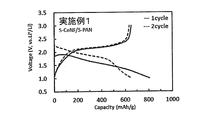
- FIG. 2 is a diagram showing a charge / discharge curve of a battery produced according to Example 1.
- the electrode material for a lithium ion battery or lithium ion capacitor of the present disclosure includes a composite powder in which the B component is supported or coated on the surface of the A component, and the A component electrochemically absorbs and releases lithium ions.
- the B component is a sulfur-modified cellulose, and the B component is 0.01% by mass or more with respect to 100% by mass of the total amount of the A component and the B component.
- the composite powder obtained is hydrophilic since the surface of the component A is supported or coated with the hydrophilic component B described later in detail.
- a binder water-based binder
- a slurry having excellent uniformity can be easily obtained, and the manufacturing time of the electrode can be shortened.
- the productivity of the electrode is significantly improved as compared with the conventional electrode material, and the capacity or output of the battery or capacitor is increased. In addition, it is possible to expand the use application.
- the composite powder of the present disclosure is the one in which the B component is supported or coated on the surface of the A component.
- the B component may be supported or coated around (surface) with the A component as a core.
- Support or coating means that the surface of component A is partially or completely covered by component B.
- composite is a concept different from mixing, and while mixed powder is a mere assembly of A component and B component, composite powder contains A component and B component in one particle constituting the powder. Both are included.
- grains of the mere mixed powder is shown in FIG. 1 (a), and the cross-sectional conceptual diagram of the particle
- FIG. 1 (b) is a conceptual view when the surface of the component A is completely covered with the component B
- B component When a simple mixed powder of A component and B component is to be dispersed in water, B component is excellent in hydrophilicity even if it is a single component, so A component and B component are easily separated when only B component is dispersed alone.
- the composite powder of the present disclosure exhibits excellent dispersibility in water because the component B is supported or coated on the surface of the component A, and both the component A and the component B can be dispersed.
- the median diameter (D50) of the composite powder in which the component B is supported or coated on the surface of the component A is preferably 0.1 ⁇ m to 30 ⁇ m, more preferably 0.5 ⁇ m to 15 ⁇ m, and still more preferably 0.55 ⁇ m to 14.5 ⁇ m Is more preferred.
- the median diameter (D50) of the composite powder in the above range it is possible to obtain an electrode material from which an electrode having excellent output characteristics and cycle life characteristics can be obtained.
- a specific surface area does not become high too much, and a binder required for electrode formation does not increase. As a result, the output characteristics and energy density of the electrode are excellent.
- adjustment of an electrical capacity is easy in design of the electrical capacity per unit area of an electrode by being 30 micrometers or less.
- the median diameter (D50) means a particle diameter at which accumulation of frequency becomes 50% by volume conversion based on volume using laser diffraction / scattering particle diameter distribution measurement method, and so on. .
- the measurement apparatus "LA-960" manufactured by HORIBA can be used.
- the content of the component B is 0.01 mass% or more, preferably 0.1 mass% or more, when the total amount of both components is 100 mass%. 0.5 mass% or more is more preferable.
- the B component is 0.01% by mass or more, the effect of imparting hydrophilicity to the A component is excellent, and the dispersibility is sufficient when producing a slurry using an aqueous binder.
- it is only for the purpose of providing hydrophilicity to the component A it is not necessary to provide the component B exceeding 10% by mass, and it may be 10% by mass or less.
- the component A is made of a material capable of electrochemically absorbing and desorbing lithium ions.
- the component A is not particularly limited as long as it is an electrode material capable of electrochemically absorbing and desorbing lithium ions.
- electrochemically absorbing lithium ions it reversibly forms an alloy (including a solid solution, an intermetallic compound, etc.) with lithium, reversibly chemically bonds with lithium, and reversibly contains lithium And so on.
- releasing lithium ions electrochemically means that lithium ions to be stored are separated.
- the component A is, for example, Li, Na, C, Mg, Al, Si, P, S, K, Ca, Sc, Ti, V, Cr, Mn, Fe, Co, Ni, Cu, Zn, Ga, Ge, It contains at least one or more elements selected from the group consisting of Y, Zr, Nb, Mo, Pd, Ag, Cd, In, Sn, Sb, W, Pb, and Bi.
- sulfur-based organic materials such as sulfur (S), sulfides of the above elements, and sulfur-modified compounds of organic compounds are preferable from the viewpoint of showing a charge-discharge plateau region similar to the component B (sulfur-modified cellulose).
- sulfur-based organic materials such as sulfides of the above elements or sulfur-modified compounds of organic compounds include metal sulfides, sulfur composite carbon, sulfur-modified natural rubber, sulfur-modified pitch, sulfur-modified anthracene, sulfur-modified polyacryl, sulfur Modified phenol, Sulfur modified polyolefin, Sulfur modified polyvinyl alcohol, Sulfur modified nylon, Sulfur modified vinyl acetate copolymer, Sulfur modified terephthalic acid, Sulfur modified diaminobenzoic acid, Sulfur modified methacrylate resin, Sulfur modified polycarbonate, Sulfur modified polystyrene, Sulfur modified N-vinyl formaldehyde copolymer, sulfur-modified polyacrylonitrile and the like can be mentioned.
- a component may consist of 1 type individual, and may consist of 2 or more types.
- sulfur-modified polyacrylonitrile is preferable because it can stably show reversible electric capacity of 500 to 700 mAh / g.
- the component A is in the form of particles, and the median diameter (D50) is preferably 0.1 ⁇ m to 30 ⁇ m, more preferably 0.5 ⁇ m to 15 ⁇ m, and still more preferably 0.55 ⁇ m to 14.5 ⁇ m.
- the median diameter (D50) is in the above range, the surface smoothness of the obtained electrode is not deteriorated, and the B component is easily supported or coated on the surface of the A component.
- the B component is sulfur-modified cellulose.
- Sulfur-modified cellulose means a material in which cellulose is dehydrogenated to be sulfurized, and is composed of a carbon skeleton derived from cellulose and sulfur bonded to the carbon skeleton. Sulfur-modified cellulose changes its appearance from white of the precursor (cellulose) to black, exhibits excellent hydrophilicity, and is insoluble in water.
- cellulose has the property of dispersing or swelling in water and absorbing water, and at 180 ° C. or more, the weight is reduced and the carbonization reaction starts.
- sulfur-modified cellulose is hydrophilic but insoluble in water, it does not swell with water, and even at 400 ° C., the weight loss is 30% by mass or less, exhibiting excellent heat resistance.
- Sulfur-modified cellulose may vary depending on production conditions such as the amount of raw materials charged and the heat treatment temperature, but it may be 10 to 60% by mass of sulfur and 20 to 60% by mass of sulfur in elemental analysis. .
- the electrode material for a lithium ion battery or lithium ion capacitor of the present disclosure includes a composite powder in which the B component is supported or coated on the surface of the A component, and may contain an optional component such as a conductive material.
- the electrode material for a lithium ion battery or lithium ion capacitor preferably contains a conductive material. This is because a further increase in output of the electrode material can be expected.
- the component B is contained so as to be supported or coated on the surface of the component A, such as containing a conductive material, it is preferable because both the hydrophilicity and the conductivity can be imparted to the surface of the component A.
- the electrode material containing an electrically-conductive material disperse
- solvent such as water
- the dispersibility in a solvent such as water can be improved by using a surfactant, an alcohol and the like in combination.
- the surfactant, alcohol and the like used in combination do not adversely affect the electrode material because they are decomposed or vaporized by heat treatment.
- the conductive material refers to a material having electronic conductivity.
- C carbon
- Al aluminum
- Ti titanium
- V vanadium
- Cr chromium
- Fe iron
- Co cobalt
- Ni nickel
- Cu copper
- Ta tantalum
- Au gold
- carbon is preferable from the viewpoint of conductivity, material cost, and small irreversible capacity.
- Examples of carbon include graphite, carbon black, carbon fiber, carbon nanotube, carbon nanohorn, graphene, hard carbon, soft carbon, glassy carbon, and vapor grown carbon fiber (VGCF (registered trademark)).
- Carbon black is particularly preferable. Carbon blacks have different properties depending on the production method, but furnace black (FB), channel black, acetylene black (AB), thermal black, lamp black, and ketjen black (KB (registered trademark)) can be used without problems.
- FB furnace black
- AB acetylene black
- KB ketjen black
- the conductive material may be used alone or in combination of two or more.
- the content of the conductive material is 0.1% by mass or more based on 100% by mass of the composite powder (in other words, the component A and the component B) in which the component B is supported or coated on the surface of the component A 30 mass% or less is preferable.
- the content is 0.1% by mass or more, the effect of imparting conductivity is sufficient.
- the content is 30% by mass or less, the capacity of the active material can be reduced, which is preferable.
- the conductive material is contained as an electrode material, it is preferable to perform desulfurization treatment in the production of a composite powder in which the component B is supported or coated on the surface of the component A and then compounded.
- the component B (sulfur-modified cellulose) can be obtained by a heat treatment process using a cellulose material (precursor) and sulfur as raw materials and contacting the cellulose material with sulfur.
- the cellulose material and the sulfur may be in physical contact, for example, a solid powder obtained by mixing the cellulose material and the sulfur, the cellulose material and the sulfur are dispersed in a solvent and dried. And the like.
- sulfur when sulfur is brought into contact with cellulose and heat-treated, sulfur diffuses in solid phase to cellulose, so that the B component (sulfur-modified cellulose) can be obtained with good yield.
- the heat treatment may be performed at a temperature at which cellulose is sulfur-modified, and preferably 200 ° C. or more and 800 ° C. or less.
- a sulfur-modified cellulose comprising a carbon skeleton derived from a cellulose material and sulfur bonded to the carbon skeleton can be synthesized.
- the temperature is 200 ° C. or more
- the cellulose material is sufficiently sulfur-modified, and the conductivity of the resulting sulfur-modified cellulose is higher than that of the one below 200 ° C. Further, by setting the temperature to 800 ° C.
- sulfur is less likely to be desorbed from the sulfur-modified cellulose, and the sulfur content is less likely to be reduced, so that it is possible to prevent the reduction in electric capacity of the electrode material as carbide.
- From the viewpoint of high yield and electrical capacity of sulfur-modified cellulose 220 ° C. or more and 600 ° C. or less are more preferable.
- From the viewpoint of excellent conductivity of the sulfur-modified cellulose 250 ° C. or more and 500 ° C. or less are more preferable.
- the atmosphere at the time of heat treatment is not particularly limited, but oxidation with oxygen may occur in the atmosphere, so it is preferable to use a non-oxygen atmosphere such as an inert gas atmosphere or a reducing atmosphere.
- a reduced pressure atmosphere a helium atmosphere, a neon atmosphere, an argon atmosphere, a nitrogen atmosphere, a hydrogen atmosphere, and a sulfur gas atmosphere can be mentioned.
- the heat treatment time may be any time as long as sulfur-modified cellulose is produced, and may be 1 hour or more and 50 hours or less, or 1 hour or more and 40 hours or less. By being in this range, cellulose is sufficiently sulfur-denatured, which is preferable because the electric capacity of the obtained composite powder is excellent. Moreover, since the heating time is not too long, the reaction of sulfur modification proceeds sufficiently, and wasteful heating energy is not consumed, which is economically preferable.
- the weight of sulfur used as the raw material may be equal to or more than the weight of the cellulose material.
- the weight of sulfur is preferably, for example, 1 to 10 times the weight of the cellulose material, and more preferably 2 to 6 times the weight.
- the sulfur modification sufficiently occurs to provide an electrode material excellent in electric capacity.
- the amount is 10 times or less, the sulfur of the raw material is unlikely to remain in the obtained electrode material, and it takes less time to carry out the desulfurization treatment in the subsequent step. Since sulfur is hydrophobic, the remaining electrode material may not exhibit sufficient hydrophilicity. In addition, if the electrode material does not show sufficient hydrophilicity, desulfurization can be performed.
- the cellulose material which is a precursor of the component B may be a carbohydrate represented by the molecular formula (C 6 H 10 O 5 ) n or a derivative thereof.
- the molecular formula (C 6 H 10 O 5) derivatives of carbohydrates represented by n, the introduction of functional groups, oxidation, reduction, etc. replacement atom, represented by the molecular formula (C 6 H 10 O 5) n It means a compound which has been modified to such an extent that the structure and properties of carbohydrates are not significantly changed.
- CeNF is cellulose which is a constituent substance such as wood; cellulose fiber in which cellulose or the like obtained from animals, algae, or bacteria is finely or physically finely ground to a maximum fiber diameter of 1 ⁇ m or less. More specifically, the cellulose fiber has a length of 0.2 ⁇ m or more, an aspect ratio (cellulose fiber length / cellulose fiber diameter (fiber diameter)) of 10 or more and 100,000 or less, and an average degree of polymerization of 100 to 100,000.
- the length of the cellulose fiber is 0.5 ⁇ m or more
- the aspect ratio (the length of the cellulose fiber / the diameter of the cellulose fiber (fiber diameter)) is 10 to 250
- the average degree of polymerization is 100 to More preferably, it is 10000 cellulose fibers.
- the average degree of polymerization refers to a value calculated by the viscosity method described in TAPPI T230 standard method.
- CeNF it is preferable that it is a cellulose fiber which has anionic group from a viewpoint which can be disintegrated efficiently to the predetermined
- the anionic group is not particularly limited, and examples thereof include a carboxylic acid group, a phosphoric acid group, a sulfonic acid group, a sulfuric acid group, or a group forming a salt with these groups, and any one of these groups is included. And may have two or more.
- the type of the salt is not particularly limited, but alkali metal salts such as sodium salt, potassium salt and lithium salt; alkaline earth metal salts such as magnesium salt, calcium salt and barium salt; onium such as ammonium salt and phosphonium salt Salts; amine salts such as primary amines, secondary amines, tertiary amines, etc. may be mentioned.
- the anionic group includes an acid type such as carboxylic acid group, phosphoric acid group, sulfonic acid group and sulfuric acid group, and a salt type such as carboxylic acid group, phosphoric acid group, sulfonic acid group and sulfuric acid base
- a preferred embodiment is that it contains a salt type anionic group, a cellulose fiber having only a salt type anionic group may be used, and a salt type anionic group and an acid type anion You may use the cellulose fiber in which the sex group is mixed.
- cellulose nanofibers (CeNF) are used as a precursor of the B component (sulfur-modified cellulose)
- the obtained sulfur-modified cellulose becomes sulfur-modified cellulose nanofibers (S-CeNF).
- the component B is fibrous sulfur-modified cellulose nanofibers (S-CeNF)
- a three-dimensional network structure having conductivity can be formed on the surface of the component A, and a sufficient current collection effect as an electrode active material It is preferable because
- S-CeNF exhibits excellent hydrophilicity without dissolving or swelling in water.
- a reversible electric capacity of 300 to 400 mAh / g can be stably shown.
- S-CeNF As the B component on the surface of the A component, it is possible to expect not only to impart hydrophilicity but also to increase the capacity of the electrode. Furthermore, since S-CeNF is fibrous, it is possible to form a three-dimensional network structure on the surface of the component A. If a three-dimensional network structure of S-CeNF is formed, the A component can be in contact with the electrolytic solution, and an output characteristic sufficient as an electrode material can be obtained.
- S-CeNF preferably has a maximum fiber diameter of 1 ⁇ m or less. More specifically, the fiber length is preferably 0.2 ⁇ m or more, and the aspect ratio (S-CeNF length / S-CeNF diameter) is preferably 10 or more and 100000 or less. Further, from the viewpoint of excellent output characteristics of the battery or capacitor, it is more preferable that the maximum fiber diameter is 1 nm or more and 500 nm or less, the fiber length is 0.5 ⁇ m or more, and the aspect ratio is 8 or more and 50000 or less.
- the fiber length is 2 ⁇ m to 200 nm, the fiber length is 0.8 ⁇ m or more, and the aspect ratio is 25 to 10000. It is possible to obtain a composite powder in which sulfur modified cellulose nanofibers having a three-dimensional network structure are supported or coated on the surface of component A, and the electrode characteristics originally expected for component A, specifically, output characteristics and cycle life characteristics It is possible to impart hydrophilicity to the component A and to exhibit excellent dispersibility without lowering the viscosity.
- the maximum fiber diameter at least 10 fibers are randomly selected from fiber images obtained using an electron beam microscope or the like, and the maximum value of the length in the minor axis direction of each fiber is determined. It is obtained by averaging the maximum values.
- the average fiber diameter at least ten or more fibers are randomly selected from fiber images obtained using an electron beam microscope or the like, and the average value of the lengths in the minor axis direction of each fiber is determined. can get.
- the aspect ratio is determined by the fiber length / fiber diameter (average fiber diameter), and the fiber length and fiber diameter are obtained as follows.
- the fiber length is a value measured by a fiber length measurement machine (FS-200 type) manufactured by KAJAANI AUTOMATION. Also, the fiber length can be measured by an equivalent device.
- the method for obtaining the composite powder in which the component B is supported or coated on the surface of the component A is not particularly limited, but methods such as mechanical milling, spray drying, fluidized bed granulation, and firing and grinding may be mentioned.
- a composite in which the surface of the component A is supported or coated with the component B can be formed by spray-drying a liquid in which the component A and the component B are dispersed in water or an organic solvent.
- the component A is a hydrophobic material
- a surfactant, alcohol or the like may be added to water. It is preferred to utilize the added solvent. The surfactant, alcohol and the like do not adversely affect the electrode material because they are decomposed or vaporized by heat treatment.
- hot air is sent from the lower part of the granulation chamber containing the component A, and the solvent in which the component B is dispersed is sprayed onto the component A while the component A is wound up into the air and allowed to flow. It is possible to form a complex in which the B component is supported or coated on the surface of the A component.
- hot air is sent from the lower part of the granulation chamber containing the precursor of the component A, and the precursor of the component A is wound up into the air and allowed to flow,
- the solvent in which the precursor is dispersed is sprayed onto the A component precursor to prepare a composite powder in which the B component precursor is supported or coated on the surface of the A component precursor, and then this composite powder is brought into contact with sulfur.
- heat treatment at 200 ° C. or higher in the molten state, a complex in which the B component is supported or coated on the surface of the A component can be formed.
- the dispersion is heat-treated at 200 ° C. or higher, and then pulverized to obtain the component B on the surface of the component A.
- the solvent used by the baking grinding method utilizes the solvent which added surfactant, alcohol, etc. to water. The surfactant, alcohol and the like do not adversely affect the electrode material because they are decomposed or vaporized by heat treatment.
- the component A when the component A is prepared first and then manufactured, particularly when it is a sulfur or sulfur-based organic material as the component A Component A is obtained by sulfiding the above element by heat treatment and sulfur-modifying an organic compound.
- this organic compound polyacrylonitrile (PAN) is preferable from the viewpoint of large electric capacity and excellent life characteristics.
- the composite powder in which the B component is supported or coated on the surface of the A component can be obtained by the step of heating to 200 ° C. or more and 800 ° C. or less.
- the component A is a sulfur-modified polyacrylonitrile obtained by sulfur-modifying polyacrylonitrile (PAN)
- PAN sulfur-modified polyacrylonitrile
- the following method may be mentioned as a method for obtaining a composite powder in which the component B is supported or coated on the surface of the component A .
- PAN is a sulfur-modified polyacrylonitrile (S-PAN; A component) by a process of heating to 200 ° C. or more and 800 ° C. or less with PAN, cellulose material, and sulfur as raw materials and in the state of contacting PAN and cellulose with sulfur.
- the cellulose material becomes sulfur-modified cellulose (corresponding to the B component), and at the same time, a composite powder in which the B component is supported or coated on the surface of the A component can be obtained.
- the weight of sulfur used as the raw material may be equal to or more than the weight of each of PAN and the cellulose material.
- the amount of sulfur is preferably 1 to 10 times the weight of each of PAN and the cellulose material, and more preferably 2 to 6 times the weight.
- the weight of sulfur as a raw material is one or more times the weight of each of PAN and a cellulose material, sulfur modification occurs sufficiently, and an electrode material excellent in electric capacity is obtained.
- the amount is 10 times or less, the sulfur of the raw material is less likely to remain in the obtained electrode material, and it takes less time to carry out the desulfurization treatment in the subsequent step. If elemental sulfur remains in the electrode material, the initial electric capacity increases, but the cycle life characteristics may deteriorate. In such a case, it is preferable to carry out desulfurization treatment.
- the desulfurization treatment is a treatment for removing elemental sulfur contained in the produced composite powder, and is not limited as long as residual sulfur can be removed by heat treatment or reduced pressure treatment.
- a heating step at 250 ° C. or higher in a reduced pressure or inert gas atmosphere may be mentioned.
- the residual sulfur can be satisfactorily removed by performing this heating for about 1 to 20 hours.
- the upper limit of the heating temperature is not particularly limited, but may be 800 ° C. or less from the viewpoint of a large electric capacity of the electrode material.
- residual sulfur may be dissolved in carbon disulfide, but since carbon disulfide is highly toxic, the above-mentioned desulfurization treatment by heat treatment is preferable.
- the lithium ion battery electrode of the present disclosure comprises the electrode material for a lithium ion battery of the present disclosure.
- the electrode for a lithium ion capacitor of the present disclosure comprises the electrode material for a lithium ion capacitor of the present disclosure.
- the lithium ion battery electrode or the lithium ion capacitor electrode may be composed of an electrode material and a current collector, and the electrode material of the present disclosure may be integrated with the current collector.
- the electrode for lithium ion batteries or the electrode for lithium ion capacitors may contain arbitrary components, such as a binder and a conductive support agent, other than the electrode material of this indication.
- a composite powder in which the B component is supported or coated on the surface of the A component in the electrode material of the present disclosure is mainly used as an active material.
- the active material refers to a substance capable of electrochemically absorbing and desorbing lithium ions.
- the electrode for example, the electrode material for lithium ion battery of the present disclosure or the electrode material for lithium ion capacitor, binder and conductive auxiliary agent, N-methyl-pyrrolidone (NMP), water, alcohol, xylene , And an appropriate solvent such as toluene are added and sufficiently kneaded, the electrode slurry obtained is coated on the surface of the current collector, dried, and pressure-controlled, to form an active material-containing layer on the current collector surface.
- NMP N-methyl-pyrrolidone
- water alcohol
- xylene xylene
- an appropriate solvent such as toluene
- the current collector is not particularly limited as long as it is a material that has electron conductivity and can conduct electricity to the held negative electrode material.
- conductive materials such as C, Ti, Cr, Fe, Mo, Ru, Rh, Ta, W, Os, Ir, Pt, Au, Cu, Ni, Al, etc. containing two or more of these conductive materials Alloys (eg, stainless steel) or the like may be used.
- C, Al, Cu, Ni, stainless steel and the like are preferable as the current collector from the viewpoints of high electron conductivity, stability in the electrolyte, oxidation resistance and reduction resistance, C, Al and stainless steel Is more preferred.
- the shape of the current collector is not particularly limited.
- a foil-like substrate, a three-dimensional substrate or the like can be used.
- Three-dimensional substrates include foam metal, mesh, woven fabric, non-woven fabric, expanded and the like.
- a primer layer on the surface of the current collector in advance.
- the primer layer may be any one as long as it has good adhesion to the electrode material layer and the current collector and has conductivity.
- a primer layer can be formed by applying a binder, which is a mixture of a carbon-based conductive additive and a binder for a primer, on a current collector.
- the thickness of the primer layer is, for example, 0.1 ⁇ m to 20 ⁇ m.
- the binder for primers can use the well-known binder used for an electrode.
- the binder contained as an optional component in the electrode for lithium ion battery or lithium ion capacitor is not limited as long as it is conventionally used as a binder for electrodes for lithium ion battery or lithium ion capacitor.
- carboxymethyl cellulose salt (CMC) acrylic resin, alginate, polyvinylidene fluoride (PVDF), polyimide (PI), polytetrafluoroethylene (PTFE), polyamide, polyamide imide, styrene butadiene rubber (SBR), polyurethane, Styrene-Ethylene-Butylene-Styrene Copolymer (SEBS), Styrene-Butadiene-Styrene Copolymer (SBS), Styrene-Isoprene-Styrene Copolymer (SIS), Styrene-Ethylene-Propylene-Styrene Copolymer (SEPS) And polyvinyl alcohol (PVA), polyvinyl alcohol (PVA
- CMC acrylic resin
- alginate PVA, SBR, etc.
- binders are water-based binders which can use water as a solvent or dispersion medium.
- the use of a water-based binder is preferable because it suppresses sulfur elution into the slurry solvent and improves the high temperature durability of the electrode.
- the hydrophobic material repels with water and becomes a dispersed powder (for example, lumps, aggregates etc.)
- a dispersed powder for example, lumps, aggregates etc.
- the composite powder of the present disclosure has the component B having excellent hydrophilicity supported or coated on the surface of the component A. Therefore, even when an aqueous binder is employed, there is no problem of difficulty in dispersion.
- the binder content is 0.1% by mass or more and 30% by mass with respect to a total of 100% by mass of the composite powder (in other words, the A and B components) in which the B component is supported or coated on the surface of the A component. % Or less is preferable, and 0.5% by mass or more and 15% by mass or less is more preferable. If the value is out of the above range, it is difficult to obtain stable life characteristics and output characteristics. That is, when the amount of the binder is small, the binding ability with the current collector is not sufficient, so it is difficult to obtain stable life characteristics. On the contrary, when the amount is too large, the electrode resistance becomes high and the output characteristics deteriorate.
- the conductive aid is a substance that helps the conductivity between active materials, and is a material that is filled or crosslinked between active materials that are separated from each other to achieve conduction between active materials or between the active material and a current collector.
- a conductive support agent contained as an optional component in a lithium ion battery electrode or a capacitor electrode those conventionally used as a conductive support agent for a lithium ion battery electrode or a capacitor electrode can be used.
- Examples include carbon materials such as acetylene black (AB), ketjen black (KB), graphite, carbon fiber, carbon nanotube, graphene, amorphous carbon, and vapor grown carbon fiber (VGCF).
- the conductive aids may be used alone or in combination of two or more.
- those capable of forming a conductive three-dimensional network structure are preferable.
- materials capable of forming a conductive three-dimensional network structure include flake-like conductive materials such as flake aluminum powder and flake stainless steel powder; carbon fibers; carbon tubes; amorphous carbon and the like.
- the content of the conductive aid is 0% by mass or more based on 100% by mass of the composite powder (in other words, the component A and the component B) in which the component B is supported or coated on the surface of the component A 20 mass% or less is preferable, and 1 mass% or more and 10 mass% or less is more preferable.
- the conductive aid is contained as needed.
- a lithium ion battery can be formed using the lithium ion battery electrode of the present disclosure.
- the lithium ion battery includes a positive electrode, a negative electrode, and an electrolyte interposed between the positive electrode and the negative electrode.
- the electrode of the present disclosure can be used as any one of the positive electrode and the negative electrode of a lithium ion battery. That is, although the electrode of the present disclosure can be used as either a positive electrode or a negative electrode of a lithium ion battery, it is excluded that the positive electrode and the negative electrode simultaneously use the same electrode among the electrodes of the present disclosure.
- a lithium ion battery When using the said electrode as a positive electrode of a lithium ion battery, a lithium ion battery can be produced by combining with the electrode more negative than the charging / discharging electric potential of the said electrode.
- a lithium ion battery when using the said electrode as a negative electrode of a lithium ion battery, a lithium ion battery can be produced by combining with the electrode more noble than the charging / discharging electric potential of the said electrode.
- the lithium ion capacitor can be set as a lithium ion capacitor using the electrode for lithium ion capacitors of this indication.
- the lithium ion capacitor also includes a positive electrode, a negative electrode, and an electrolyte interposed between the positive electrode and the negative electrode.
- the electrode of the present disclosure is used as an electrode of a lithium ion capacitor, the electrode can be used as either a positive electrode or a negative electrode, and the positive electrode and the negative electrode may use the same electrode at the same time.
- a lithium ion doped negative electrode as an electrode to be a negative electrode in advance before assembling a lithium ion capacitor.
- the lithium ion doping method is not particularly limited as long as the electrode can be doped with lithium, but, for example, non-patent literature (Sakamoto Taichi et al., "Collection of measurement and analysis data of lithium secondary battery members” Technical Information Association publication, 30 (1) Electrochemical doping, (2) Bonding doping of lithium metal foil, (3) mechanical lithium doping using high-speed planetary mill, etc. as described in can give.
- examples of the counter electrode include Li, Na, C, Mg, Al, Si, P, K, Ca, Sc, Ti, V, Cr, Mn, Fe, Co, Ni At least one element selected from the group consisting of Cu, Zn, Ga, Ge, Y, Zr, Nb, Mo, Pd, Ag, Cd, In, Sn, Sb, W, Pb, and Bi; Electrodes containing materials such as alloys containing elements; oxides, sulfides and halides of these elements; sulfur-based organic materials such as sulfur-modified compounds of organic compounds; and the like (in other words, negative electrode materials). These negative electrode materials may be used alone or in combination of two or more.
- a counter electrode positive electrode
- LiCoO 2 , L iNiO 2 , LiMnO 2 , LiNi 0.33 Mn 0.33 Co 0.33 O 2 LiNi 0.5 Mn 0.3 Co 0.2 O 2 , LiNi 0.6 Mn 0.2 Co 0.2 O 2 , LiNi 0.8 Mn 0.1 Co 0.1 O 2 , LiMn 2 O 4 , LiNi 0.5 Mn 1.5 O 4
- LiFePO 4 LiFe 0.5 Mn 0.5 PO 4 , LiMnPO 4 , LiCoPO 4 4, LiNiPO 4, Li 3 V 2 (PO 4) 3, LiV 2 O 5, LiVO 2, LiNb 2 O 5, LiNbO 2, LiFeO 2, LiMgO 2, LiCaO 2, LiTiO 2, LiCrO 2, LiRuO 2, LiCuO 2, LiZnO 2, LiMoO 2, LiTaO 2 or LiWO 2
- An electrolytic solution is obtained by dissolving a supporting salt in a solvent.
- the solvent of the electrolytic solution is not particularly limited, but cyclic carbonates such as ethylene carbonate (EC), propylene carbonate (PC) and butylene carbonate; ethers such as tetrahydrofuran; hydrocarbons such as hexane; and ⁇ -butyl A lactone system such as lactone can be used.
- cyclic carbonate-based electrolytes such as EC or PC are preferable from the viewpoint of discharge rate characteristics.
- the discharge rate is an index based on a constant current discharge of a cell having a capacity of a nominal capacity value to set a current value that completely discharges in 1 hour as a “1C rate”, for example, 5 hours.
- the current value for complete discharge is described as "0.2 C rate”, and the current value for complete discharge in 10 hours is described as “0.1 C rate”.
- the charge rate is an index based on a constant current charge of a cell having a capacity of a nominal capacity value to set a current value to be fully charged in one hour as a “1 C rate”, for example, 1
- the current value for full charge in minutes is "60C rate”
- the current value for full charge in 6 minutes is "10C rate”
- the current value for full charge in 5 hours is "0.2C rate”
- full in 10 hours full in 10 hours
- the current value to be charged is described as "0.1 C rate”.
- EC Since EC is usually solid at normal temperature, EC alone does not function as an electrolyte. However, the mixed solvent obtained by mixing with PC, dimethyl carbonate (DMC), diethyl carbonate (DEC), ethyl methyl carbonate (EMC) or the like functions as an electrolytic solution usable even at normal temperature.
- DMC dimethyl carbonate
- DEC diethyl carbonate
- EMC ethyl methyl carbonate
- EC ethylene carbonate
- DEC diethylene carbonate
- EC-DMC dimethyl carbonate
- EC-PC ethylene carbonate
- EC-DEC or EC-PC is suitably used.
- the salt generally used to a lithium ion battery or a lithium ion capacitor can be used.
- lithium hexafluorophosphate (LiPF 6 ) is preferably used.
- LiPF 6 lithium hexafluorophosphate
- the concentration of the electrolytic solution is not particularly limited, but is preferably 0.1 to 3 mol / L, and more preferably 0.8 to 2 mol / L.
- the structure of the lithium ion battery or lithium ion capacitor is not particularly limited, but an existing form or structure such as a laminated type or a wound type can be adopted. That is, the electrode group in which the positive electrode and the negative electrode face each other with the separator interposed therebetween is wound or sealed in a state in which the electrode group is immersed in the electrolytic solution, to form a secondary battery or a capacitor.
- An electricity storage device (in particular, a lithium ion battery or a lithium ion capacitor) using an electrode material for a lithium ion battery or a lithium ion capacitor according to the present disclosure has a high capacity and a high output.
- an electrode of the present disclosure there are an electrode for lithium ion battery and an electrode for lithium ion capacitor.
- a lithium ion battery is manufactured and tested.
- the lithium ion capacitor can be manufactured in the same manner as the lithium ion battery except that the operation of the counter electrode is mainly different.
- the battery can be manufactured in the same manner as the battery described later except that the conventional lithium ion capacitor positive electrode is used as the positive electrode and the electrode of the present disclosure is used as the negative electrode.
- the electrode of the present disclosure is used as an electrode for a lithium ion capacitor, for example, an electrode manufactured by applying a slurry consisting of activated carbon, a binder and a conductive additive to an aluminum foil and heat treating it as a counter electrode Can.
- the activated carbon of such a lithium ion capacitor is formed of an infinite number of fine pores, preferably a carbon material having a large specific surface area.
- a carbon material such as petroleum coke and an alkali metal compound such as potassium hydroxide are heated at 600 to 1500 ° C. in a non-oxygen atmosphere to allow alkali metal to penetrate between graphite crystal layers. It is obtained by activating the reaction.
- the median diameter (D50) of the activated carbon particles is preferably 0.5 to 30 ⁇ m.
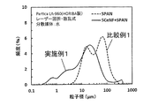
- volume based particle size distribution With respect to the obtained powder, volume based particle size distribution was measured by laser diffraction / scattering equation using water as a dispersion medium. As a measuring apparatus, “LA-960” manufactured by HORIBA was used. It measured using the laser beam of wavelength 650nm and 405 nm. The results are shown in FIG.
- the obtained slurry was applied on a 20 ⁇ m thick aluminum foil as a current collector, and dried under reduced pressure at 160 ° C. for 12 hours to obtain a test electrode.
- the powder of the sulfur modified compound was used as an active material.
- the obtained test electrode was used as a positive electrode, and the coating amount of the slurry was adjusted so that the positive electrode capacity per unit area of one side of the positive electrode was 1 mAh / cm 2 .
- EC ethylene carbonate
- DEC diethyl CR2032 coin cell equipped with carbonate
- Test electrode obtained as positive electrode; microporous polypropylene membrane (thickness 20 ⁇ m) as separator; SiO whose electrochemical irreversible capacity is canceled as negative electrode; 1 M LiPF 6 as electrolyte (ethylene carbonate (EC): diethyl carbonate (DEC)
- EC ethylene carbonate
- DEC diethyl carbonate
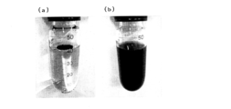
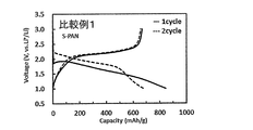
- Example 1 A battery was produced in the same manner as in Comparative Example 1 except that the composite powder obtained by the following method was used as the powder of the sulfur-modified compound. The evaluation of the dispersibility of the composite powder obtained in the steps up to the production of the battery in water, the charge / discharge test of the battery, and the test of leaving at high temperature were performed on the electrode. The results are shown in Table 1, FIG. 2, FIG. 3 and FIG.
- the resulting mixture was heated at 350 ° C. for 5 hours. After heating, the mixture is crushed by a stirring grinder, classified by a sieve of 325 mesh (45 ⁇ m mesh), and a composite powder (S-CeNF + S-PAN) in which sulfur modified cellulose is supported or coated on the surface of sulfur modified polyacrylonitrile powder. Got).
- the median diameter (D50) of the obtained powder was 14.2 ⁇ m. This value is obtained based on the data shown in FIG.
- Example 1 shows superior water dispersibility to Comparative Example 1.
- the powder of Comparative Example 1 has a peak with a narrow width at a large particle size value compared to the powder of Example 1, and the powder of Example 1 has a broad peak at a small particle size value. It can be seen that the powder of 1 is well dispersed in water.
- the electrode of Comparative Example 1 has a decrease in discharge capacity of about 4.9% from 674 mAh / g in one cycle to 641 mAh / g in 100 cycles, while Example 1 The electrode of Example 1 had a decrease in discharge capacity of about 4.9% from one cycle of 652 mAh / g to 100 cycles of 620 mAh / g, and exhibited the same reversible capacity and cycle life characteristics as the electrode of Comparative Example 1.
- the electrode of Reference Example 1 is about 19% reduction in discharge capacity from 1 cycle of 353 mAh / g to 100 cycles of 287 mAh / g, and although it has excellent cycle life characteristics to a certain extent, Example 1 and Comparative Example 1 It has been shown that especially the electrical capacity is low compared to the capacity above 600 mAh / g. In the batteries using the electrodes of Example 1 and Comparative Example 1, no significant change by visual observation was observed, and no battery swelling due to gas generation was confirmed.
Landscapes
- Chemical & Material Sciences (AREA)
- Engineering & Computer Science (AREA)
- Chemical Kinetics & Catalysis (AREA)
- Electrochemistry (AREA)
- General Chemical & Material Sciences (AREA)
- Power Engineering (AREA)
- Materials Engineering (AREA)
- Microelectronics & Electronic Packaging (AREA)
- Manufacturing & Machinery (AREA)
- Composite Materials (AREA)
- Electric Double-Layer Capacitors Or The Like (AREA)
- Battery Electrode And Active Subsutance (AREA)
Abstract
電極特性を低下させることなく、疎水性の活物質の欠点を補い、疎水性の活物質に親水性を付与し、優れた分散性を発揮できるリチウムイオン電池用またはリチウムイオンキャパシタ用の電極材料を提供する。 リチウムイオン電池用またはリチウムイオンキャパシタ用の電極材料であって、前記電極材料は、A成分の表面にB成分が担持または被覆された複合粉末を含み、A成分がリチウムイオンを電気化学的に吸蔵および放出することができる材料からなり、B成分が、硫黄変性セルロースであり、前記A成分および前記B成分の合計量100質量%に対し、前記B成分が0.01質量%以上である、リチウムイオン電池用またはリチウムイオンキャパシタ用の電極材料。
Description
本発明は、リチウムイオン電池用電極材料、リチウムイオンキャパシタ用電極材料、電極、電池、キャパシタ、電気機器、リチウムイオン電池用電極材料の製造方法、およびリチウムイオンキャパシタ用電極材料の製造方法に関する。
近年、ノートパソコン、スマートフォン、携帯ゲーム機器、PDA等の携帯電子機器;電気自動車;家庭太陽光発電等の普及に伴い、これらに用いられる、繰り返し充放電が可能な蓄電デバイスの性能に対する要求が高まっている。携帯電子機器をより軽量化し、且つ、長時間の使用を可能とするため、また電気自動車の長距離走行を可能とするために、蓄電デバイスの小型化および高エネルギー密度化が要求されている。蓄電デバイスとしては、二次電池やキャパシタ等が挙げられる。現在、特に、二次電池が携帯電子機器の電源、電気自動車用電源、家庭用蓄電池などとして用いられている。
従来、二次電池としては、ニッケル-カドミウム(Ni-Cd)電池、ニッケル-水素(Ni-MH)電池等のアルカリ二次電池が主流であったが、上記した小型化および高エネルギー密度化の要請から、リチウムイオン電池の使用が増大する傾向にある。また、出力密度に優れたキャパシタの中では、リチウムイオンキャパシタは、高エネルギー密度であることから、出力用途での使用の増大が期待される。
リチウムイオン電池は、一般的に、正極、負極、電解液または電解質、セパレータなどから構成される。電極(正極または負極)は、例えば、電極材料(主に活物質をいう)、バインダ、および導電助剤からなるスラリーを、集電体上に塗工し乾燥することで作製される。
市販のリチウムイオン電池の正極材料(主に正極活物質をいう)としては、コバルト酸リチウム(LiCoO2)や三元系材料(Li(Ni,Co,Mn)O2)などが使用されている。これらの実用的な放電容量は150~160mAh/g程度である。コバルトやニッケルは、レアメタルであることから、これらのレアメタルに代わる正極材料が求められている。また、負極材料(主に負極活物質をいう)としては、グラファイト(黒鉛)やハードカーボン、チタン酸リチウム(Li4Ti5O12)などが使用されている。これらの実用的な放電容量は150~350mAh/g程度であるが、更なる高容量化が求
められている。
められている。
多岐にわたる電極材料のうち、硫黄は、単位重量当たりの反応電子数が大きく、理論容量が1672mAh/gで、材料コストも低いため、魅力的な電極材料として知られている。また、硫黄は、2V(vs.Li/Li+)付近に充放電プラトーを示し、正極としても、負極としても利用することが可能である。
しかし、硫黄からなる電極は、Li化(正極として用いた場合では放電、負極として用いた場合では充電)する際に、多硫化リチウム(Li2Sx:x=2~8)や低分子量の硫化物が生成し、電解液中(特に、カーボネート系溶媒)に溶出しやすく、可逆的な安定した容量を維持することが困難であった。そこで、電解液中への硫黄溶出を抑制するため、-CS-CS-結合または-S-S-結合をもつ硫黄系有機材料の他、硫黄に硫黄以外の材料を複合化した材料などの硫黄系の電極材料が提案されている。
また、最近では、硫黄を含有する有機化合物が電極材料として提案されている(特許文献1~7および非特許文献1~5)。なかでも、硫化したポリアクリロニトリル(硫黄変性ポリアクリロニトリル)は、500~700mAh/gの可逆容量と、安定した寿命特性が得られることが見出されている。
幸琢寛ら、「リチウムイオン電池活物質の開発と電極材料技術」,サイエンス&テクノロジー出版、pp.194-222(2014)
小島敏勝ら、第53回電池討論会講演要旨集,3C27,p.202(2012)
幸琢寛ら、第53回電池討論会講演要旨集,3C28,p.203(2012)
小島敏勝ら、第54回電池討論会講演要旨集,1A08,p.7(2013)
小島敏勝ら、第54回電池討論会講演要旨集,3E08,p.344(2013)
リチウムイオン電池やリチウムイオンキャパシタの電極には、活物質を結着するバインダとして、ポリフッ化ビニリデン(PVDF)が、広く実用化され普及している。PVDFは、高い柔軟性と優れた耐酸化性・耐還元性を示すバインダであり、これをスラリーとする際の溶媒としてN-メチルピロリドン(NMP)等の有機溶媒が好ましく用いられる。しかしながら、これらの有機溶媒は、製造コストおよび環境への負荷の負荷が比較的高い。このため、脱有機溶媒が求められる。さらに、NMPは、硫黄系の電極材料を用いた場合、電極材料中の硫黄を溶解させるため、電極の容量低下を招く。また、PVDFは、高温の電解液中で膨潤しやすく、PVDFの膨潤は、電極材料層の電子導電性を低下させ、電極の出力特性とサイクル寿命特性を悪化させる1つの要因となっている。したがって、NMP等の有機溶媒を用いず、且つ電解液中で膨潤しにくいバインダを用いることが望ましい。
近年、高温の電解液中でも膨張しにくいバインダとして、カルボキシメチルセルロース(CMC)、アクリル系樹脂、およびアルギン酸などの水系バインダが注目されている。電極に水系バインダを用いることで、電極の製造工程で調製するスラリーの溶媒として水を選択できる。このため、製造コスト面と環境面でも有望である。また、水に硫黄が溶けないため、スラリーの溶媒として水を用いれば、スラリーの溶媒への硫黄溶出による容量低下を防ぐことができる。
しかし、これまで報告されてきた電極材料として用いられる各種の硫黄系材料は、疎水性で水に対する濡れ性が低い。したがって、水を溶媒或いは分散媒とするバインダ(言い換えれば、水系バインダ)を用いる場合、スラリー調製の混練工程において、疎水性の硫黄系材料の分散が困難であった。疎水性の硫黄系材料の分散性を高めようとして、親水性を付与するためには、界面活性剤などを用いることが容易に思いつく。しかしながら、多くの界面活性剤は、電池として用いた場合、過充電や高温放置などで分解しガスを発生させ、電池特性を低下させる。
本発明は、上記従来技術の現状に鑑みてなされたものであり、その主な目的は、電極特性を低下させることなく、疎水性の活物質の欠点を補い、疎水性の活物質に親水性を付与し、優れた分散性を発揮できるリチウムイオン電池用またはリチウムイオンキャパシタ用の電極材料を提供することにある。
本発明者らは、上述した従来技術の現状に留意しつつ鋭意研究を重ねてきた結果、リチウムイオンを電気化学的に吸蔵および放出することができる材料からなる成分が、その表面に、硫黄変性処理したセルロースが担持または被覆された複合粉末を形成することで、スラリーの製造工程において、水および水系バインダを用いても、優れた分散性を示すこと、および出力特性に優れた電極が得られることを見出し、ここに本発明を完成するに至った。
本発明の第一は、リチウムイオン電池用またはリチウムイオンキャパシタ用の電極材料であって、前記電極材料は、A成分の表面にB成分が担持または被覆された複合粉末を含み、A成分がリチウムイオンを電気化学的に吸蔵および放出することができる材料からなり、B成分が、硫黄変性セルロースであり、前記A成分および前記B成分の合計量100質量%に対し、前記B成分が0.01質量%以上である、リチウムイオン電池用またはリチウムイオンキャパシタ用の電極材料に関する。
前記リチウムイオン電池用またはリチウムイオンキャパシタ用の電極材料において、前記硫黄変性セルロースが硫黄変性セルロースナノファイバーであることが好ましい。
前記リチウムイオン電池用またはリチウムイオンキャパシタ用の電極材料において、前記硫黄変性セルロースナノファイバーの最大繊維径が1μm以下であることが好ましい。
前記リチウムイオン電池用またはリチウムイオンキャパシタ用の電極材料において、前記電極材料が、さらに導電材料を含有し、前記A成分、前記B成分および前記導電材料の合計量100質量%に対し、前記導電材料が0.1質量%以上30質量%以下であることが好ましい。
前記リチウムイオン電池用またはリチウムイオンキャパシタ用の電極材料において、前記リチウムイオンを電気化学的に吸蔵および放出することができる材料が、硫黄または硫黄系有機材料であることが好ましい。
前記リチウムイオン電池用またはリチウムイオンキャパシタ用の電極材料において、前記リチウムイオンを電気化学的に吸蔵および放出することができる材料が、硫黄変性ポリアクリロニトリルであることが好ましい。
本発明の第二は、前記電極材料からなる、リチウムイオン電池用またはリチウムイオンキャパシタ用の電極に関する。また、前記電極材料および集電体からなる、リチウムイオン電池用またはリチウムイオンキャパシタ用の電極であってよい。
前記リチウムイオン電池用またはリチウムイオンキャパシタ用の電極において、前記電極がバインダを含有し、前記バインダが水系バインダであることが好ましい。
本発明の第三は、正極、負極、および前記正極と前記負極との間に介在する電解質を備える、リチウムイオン電池またはリチウムイオンキャパシタであって、前記正極および前記負極のうちいずれか一方が、前記電極である、リチウムイオン電池またはリチウムイオンキャパシタに関する。
本発明の第四は、前記リチウムイオン電池またはリチウムイオンキャパシタを有する電気機器に関する。
本発明の第五は、前記リチウムイオン電池用またはリチウムイオンキャパシタ用の電極材料の製造方法であって、前記リチウムイオンを電気化学的に吸蔵および放出することができる材料と、セルロース材料と、硫黄とを接触させた状態で200℃以上800℃以下に加熱する工程を有する、リチウムイオン電池用またはリチウムイオンキャパシタ用の電極材料の製造方法に関する。
前記リチウムイオン電池用またはリチウムイオンキャパシタ用の電極材料の製造方法において、前記リチウムイオンを電気化学的に吸蔵および放出することができる材料が、硫黄変性ポリアクリロニトリルであることが好ましい。
前記リチウムイオン電池用またはリチウムイオンキャパシタ用の電極材料の製造方法において、前記加熱する工程の後、さらに減圧または不活性ガス雰囲気中、250℃以上に加熱する工程を有することが好ましい。
前記リチウムイオン電池用またはリチウムイオンキャパシタ用の電極材料の製造方法において、リチウムイオンを電気化学的に吸蔵および放出することができる材料と、セルロース材料と、硫黄とを接触させた状態で200℃以上800℃以下に加熱する工程の後、または、減圧または不活性ガス雰囲気中、250℃以上に加熱する工程の後、導電材料を配合することが好ましい。
前記リチウムイオン電池用またはリチウムイオンキャパシタ用の電極材料の製造方法において、前記セルロース材料が、最大繊維径1μm以下のセルロースナノファイバーであることが好ましい。
本発明によれば、電極特性を低下させることなく、疎水性の活物質の欠点を補い、疎水性の活物質に親水性を付与し、優れた分散性を発揮できるリチウムイオン電池用またはリチウムイオンキャパシタ用の電極材料を提供することができる。
[リチウムイオン電池用またはリチウムイオンキャパシタ用の電極材料]
本開示のリチウムイオン電池用またはリチウムイオンキャパシタ用の電極材料は、A成分の表面にB成分が担持または被覆された複合粉末を含み、A成分がリチウムイオンを電気化学的に吸蔵および放出することができる材料からなり、B成分が、硫黄変性セルロースであり、前記A成分および前記B成分の合計量100質量%に対し、前記B成分が0.01質量%以上である。
本開示のリチウムイオン電池用またはリチウムイオンキャパシタ用の電極材料は、A成分の表面にB成分が担持または被覆された複合粉末を含み、A成分がリチウムイオンを電気化学的に吸蔵および放出することができる材料からなり、B成分が、硫黄変性セルロースであり、前記A成分および前記B成分の合計量100質量%に対し、前記B成分が0.01質量%以上である。
この構成によれば、A成分が、疎水性の材料であっても、A成分の表面に、詳しくは後述する親水性のB成分が担持または被覆されているので、得られる複合粉末は親水性を有する。したがって、当該複合粉末を電極材料とし、水を溶媒或いは分散媒とするバインダ(水系バインダ)を用いても、容易に且つ均一性に優れたスラリーを得ることができ、電極の製造時間の短縮を図ることができる。そのため、本開示に係る、リチウムイオン電池またはリチウムイオンキャパシタ用の電極材料によれば、従来の電極材料と比べて電極の生産性が大幅に向上し、電池またはキャパシタの高容量化と高出力化を両立させることが可能となり、利用用途を拡大することが可能となる。
<複合粉末>
本開示の複合粉末は、A成分の表面にB成分が担持または被覆されたものである。例えば、A成分を核としてその周囲(表面)にB成分が担持または被覆されたものであってよい。担持または被覆とは、A成分の表面がB成分によって部分被覆または完全被覆されていることを意味する。
本開示の複合粉末は、A成分の表面にB成分が担持または被覆されたものである。例えば、A成分を核としてその周囲(表面)にB成分が担持または被覆されたものであってよい。担持または被覆とは、A成分の表面がB成分によって部分被覆または完全被覆されていることを意味する。
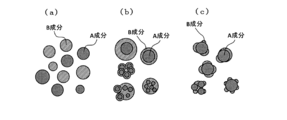
また、複合は、混合とは異なる概念であり、混合粉末がA成分とB成分との単なる集合であるのに対して、複合粉末は当該粉末を構成する1つの粒子中にA成分とB成分の両方が含まれている。一例として、図1(a)に単なる混合粉末の粒子の断面概念図、並びに図1(b)および(c)に複合粉末の粒子の断面概念図を比較して示す。図1(b)は、A成分の表面がB成分によって完全被覆された場合の概念図であり、図1(c)は、A成分の表面がB成分によって部分被覆(言い換えれば、担持)された場合の概念図である。
A成分とB成分の単なる混合粉末を水に分散しようとする場合、B成分は単体でも親水性に優れるため、B成分のみが単体で分散することにより、A成分とB成分が分離しやすいのに対し、本開示の複合粉末は、A成分の表面にB成分が担持または被覆されているため、水に対する優れた分散性を示し、A成分もB成分も分散した状態とすることができる。
A成分の表面にB成分が担持または被覆された複合粉末は、メディアン径(D50)が0.1μm以上30μm以下が好ましく、0.5μm以上15μm以下がより好ましく、0.55μm以上14.5μm以下がさらに好ましい。複合粉末のメディアン径(D50)を上記の範囲内にすることで、出力特性およびサイクル寿命特性に優れた電極が得られる電極材料とすることができる。0.1μm以上であることにより、比表面積が高くなりすぎず、電極形成に必要なバインダが多くならない。その結果、電極の出力特性とエネルギー密度に優れる。一方、30μm以下であることにより、電極の単位面積当たりの電気容量の設計において電気容量の調整が容易である。
ここで、メディアン径(D50)とは、レーザー回折・散乱式粒子径分布測定法を用い、体積基準の体積換算で頻度の累積が50%になる粒子径を意味し、以降においても同様である。測定装置は、HORIBA製「LA-960」などを用いることができる。
複合粉末全体におけるA成分とB成分の割合としては、両者の合計量を100質量%とした場合に、B成分が0.01質量%以上であるところ、0.1質量%以上が好ましく、0.5質量%以上がより好ましい。B成分が0.01質量%以上であることにより、A成分に対する親水性付与の効果に優れ、水系バインダを用いたスラリーを作製する際に十分な分散性を有する。なお、A成分に親水性を付与する目的だけであれば、10質量%を超えるB成分を設ける必要はなく、10質量%以下であってよい。
(A成分)
A成分は、リチウムイオンを電気化学的に吸蔵および放出することができる材料からなる。A成分は、リチウムイオンを電気化学的に吸蔵および放出することができる電極材料であれば特に限定されない。リチウムイオンを電気化学的に吸蔵することとしては、リチウムと可逆的に合金(固溶体、金属間化合物などを含む)を形成する、リチウムと可逆的に化学結合する、またリチウムを可逆的に内包することなどが挙げられる。また、リチウムイオンを電気化学的に放出することとは、吸蔵されるリチウムイオンが離れることをいう。
A成分は、リチウムイオンを電気化学的に吸蔵および放出することができる材料からなる。A成分は、リチウムイオンを電気化学的に吸蔵および放出することができる電極材料であれば特に限定されない。リチウムイオンを電気化学的に吸蔵することとしては、リチウムと可逆的に合金(固溶体、金属間化合物などを含む)を形成する、リチウムと可逆的に化学結合する、またリチウムを可逆的に内包することなどが挙げられる。また、リチウムイオンを電気化学的に放出することとは、吸蔵されるリチウムイオンが離れることをいう。
A成分は、例えば、Li、Na、C、Mg、Al、Si、P、S、K、Ca、Sc、Ti、V、Cr、Mn、Fe、Co、Ni、Cu、Zn、Ga、Ge、Y、Zr、Nb、Mo、Pd、Ag、Cd、In、Sn、Sb、W、Pb、およびBiよりなる群から選ばれた少なくとも一種以上の元素を含む。また、これらの元素が含まれる合金;これらの元素の酸化物、硫化物、およびハロゲン化物;有機化合物の硫黄変性化合物などの硫黄系有機材料;などであってもよい。
これらのなかでも、B成分(硫黄変性セルロース)と近い充放電プラトー域を示す観点から、S(硫黄)、上記元素の硫化物、および有機化合物の硫黄変性化合物などの硫黄系有機材料が好ましい。上記元素の硫化物、または有機化合物の硫黄変性化合物などの硫黄系有機材料としては、例えば、硫化金属、硫黄複合カーボン、硫黄変性天然ゴム、硫黄変性ピッチ、硫黄変性アントラセン、硫黄変性ポリアクリル、硫黄変性フェノール、硫黄変性ポリオレフィン、硫黄変性ポリビニルアルコール、硫黄変性ナイロン、硫黄変性酢酸ビニル共重合体、硫黄変性テレフタル酸、硫黄変性ジアミノ安息香酸、硫黄変性メタクリル樹脂、硫黄変性ポリカーボネート、硫黄変性ポリスチレン、硫黄変性N-ビニルホルムアルデヒド共重合体、および硫黄変性ポリアクリロニトリルなどが挙げられる。A成分は1種単独からなるものでもよく、2種以上からなるものであってよい。
これらのなかでも、特に、硫黄変性ポリアクリロニトリルは、電気容量が500~700mAh/gもの可逆的な電気容量を安定して示すことができるため好適である。
A成分は、粒子状であって、メディアン径(D50)が0.1μm以上30μm以下が好ましく、0.5μm以上15μm以下がより好ましく、0.55μm以上14.5μm以下がさらに好ましい。メディアン径(D50)が上記範囲内であれば、得られる電極の表面平滑性を悪化させず、且つA成分の表面にB成分を担持または被覆されやすい。
(B成分)
B成分は、硫黄変性セルロースである。硫黄変性セルロースとは、セルロースが脱水素反応を起こして硫化した材料を意味し、セルロースに由来する炭素骨格と該炭素骨格と結合した硫黄とからなる。硫黄変性セルロースは、前駆体(セルロース)の白色から黒色に見た目が変化しており、優れた親水性を示し、水には不溶である。
B成分は、硫黄変性セルロースである。硫黄変性セルロースとは、セルロースが脱水素反応を起こして硫化した材料を意味し、セルロースに由来する炭素骨格と該炭素骨格と結合した硫黄とからなる。硫黄変性セルロースは、前駆体(セルロース)の白色から黒色に見た目が変化しており、優れた親水性を示し、水には不溶である。
セルロースと硫黄変性セルロースの違いについて述べる。セルロースは、水に分散または水を吸収して膨潤する性質があるとともに、180℃以上では、重量減少して炭化反応が始まる。しかし、硫黄変性セルロースは、親水性はあるものの水には不溶であるため、水により膨潤せず、400℃でも重量減少は30質量%以下であり、優れた耐熱性を示す。硫黄変性セルロースは、原料の仕込み量や熱処理温度などの製造条件によっても異なるが、元素分析で10~60質量%が硫黄で構成されてよく、20~60質量%が硫黄で構成されていてよい。
<導電材料>
本開示のリチウムイオン電池用またはリチウムイオンキャパシタ用の電極材料は、A成分の表面にB成分が担持または被覆された複合粉末を含む他、導電材料などの任意成分を含んでよい。
本開示のリチウムイオン電池用またはリチウムイオンキャパシタ用の電極材料は、A成分の表面にB成分が担持または被覆された複合粉末を含む他、導電材料などの任意成分を含んでよい。
リチウムイオン電池用またはリチウムイオンキャパシタ用の電極材料は、導電材料を含有していることが好ましい。電極材料のさらなる高出力化が期待できるためである。特に、B成分に導電材料が含まれるなど、A成分の表面に担持または被覆されるように含まれる場合、A成分の表面に親水性と導電性の両方を付与できるため好ましい。
また、導電材料を含有する電極材料の製造方法としては、例えば、水などの溶媒に、A成分、B成分の前駆体、導電材料および硫黄を分散し、熱処理することが挙げられる。A成分を水などの溶媒に分散する際、継粉(ダマ又は凝集体)になった場合は、界面活性剤やアルコールなどを併用することにより、水などの溶媒への分散性を向上させることができる。併用する界面活性剤やアルコールなどは、熱処理することによって、分解または気化するので、電極材料に悪影響を及ぼさない。
導電材料とは、電子導電性を有する材料をいう。例えば、C(カーボン)、Al(アルミニウム)、Ti(チタン)、V(バナジウム)、Cr(クロム)、Fe(鉄)、Co(コバルト)、Ni(ニッケル)、Cu(銅)、Ta(タンタル)、Pt(白金)、Au(金)から選ばれる金属;これらの金属からなる合金;および導電性を有するセラミックや高分子などであってもよい。これらの中でも、導電性と材料コスト、不可逆容量が少ない観点からカーボンが好ましい。カーボンとしては、グラファイト、カーボンブラック、カーボンファイバー、カーボンナノチューブ、カーボンナノホーン、グラフェン、ハードカーボン、ソフトカーボン、グラッシーカーボン、および気相成長炭素繊維(VGCF;登録商標)等が挙げられる。このうち特にカーボンブラックが好ましい。カーボンブラックは、製造方法により性質が異なるが、ファーネスブラック(FB)、チャンネルブラック、アセチレンブラック(AB)、サーマルブラック、ランプブラック、およびケッチェンブラック(KB;登録商標)などが問題なく使用できる。導電材料は、1種単独で用いてもよく、2種以上を併用してもよい。
導電材料の含有量は、A成分の表面にB成分が担持または被覆された複合粉末(言い換えれば、A成分およびB成分)、および導電材料の合計100質量%に対し、0.1質量%以上30質量%以下が好ましい。0.1質量%以上であることにより、導電性付与の効果が十分であり、30質量%以下であることにより、活物質容量も低くなりずぎないため好ましい。
導電材料を、電極材料として含有する場合は、A成分の表面にB成分が担持または被覆された複合粉末の製造において、脱硫黄処理を行った後、配合することが好ましい。
[リチウムイオン電池用またはリチウムイオンキャパシタ用の電極材料の製造]
まず、リチウムイオン電池用またはリチウムイオンキャパシタ用の電極材料が含む、A成分の表面にB成分が担持または被覆された複合粉末の製造について述べる。B成分(硫黄変性セルロース)は、セルロース材料(前駆体)と硫黄とを原料とし、セルロース材料に硫黄を接触させた状態で、加熱処理する工程により得ることができる。セルロースに硫黄を接触させた状態とは、セルロース材料と硫黄とが物理的に接触していればよく、例えば、セルロース材料と硫黄を混合した固形粉末、セルロース材料と硫黄を溶媒中に分散し乾燥したものなどが挙げられる。このようにセルロースに硫黄を接触させて加熱処理することで、セルロースに硫黄が固相拡散するため、収率よくB成分(硫黄変性セルロース)を得ることができる。
まず、リチウムイオン電池用またはリチウムイオンキャパシタ用の電極材料が含む、A成分の表面にB成分が担持または被覆された複合粉末の製造について述べる。B成分(硫黄変性セルロース)は、セルロース材料(前駆体)と硫黄とを原料とし、セルロース材料に硫黄を接触させた状態で、加熱処理する工程により得ることができる。セルロースに硫黄を接触させた状態とは、セルロース材料と硫黄とが物理的に接触していればよく、例えば、セルロース材料と硫黄を混合した固形粉末、セルロース材料と硫黄を溶媒中に分散し乾燥したものなどが挙げられる。このようにセルロースに硫黄を接触させて加熱処理することで、セルロースに硫黄が固相拡散するため、収率よくB成分(硫黄変性セルロース)を得ることができる。
加熱処理は、セルロースが硫黄変性する温度であればよく、200℃以上800℃以下とすることが好ましい。これにより、セルロース材料に由来する炭素骨格と該炭素骨格と結合した硫黄とからなる硫黄変性セルロースが合成できる。200℃以上であることにより、セルロース材料が十分に硫黄変性し、得られる硫黄変性セルロースの導電性は、200℃未満のものと比べて高い。また、800℃以下であることにより、硫黄変性セルロースから硫黄が脱離しにくく、硫黄含有量が減少しにくいため、炭化物となり電極材料の電気容量が低下することを防ぐことができる。硫黄変性セルロースの収率と電気容量が高い観点から、220℃以上600℃以下がより好ましい。また、硫黄変性セルロースの導電性に優れる観点から、250℃以上500℃以下がさらに好ましい。
加熱処理時の雰囲気は、特に限定されないが、大気中であると酸素による酸化が起こりうるので、不活性ガス雰囲気や還元雰囲気などの非酸素雰囲気とすることが好ましい。具体的には、例えば、減圧雰囲気、ヘリウム雰囲気、ネオン雰囲気、アルゴン雰囲気、窒素雰囲気、水素雰囲気、および硫黄ガス雰囲気が挙げられる。
加熱処理の時間は、硫黄変性セルロースが生成される時間であればよく、1時間以上50時間以下であってよく、1時間以上40時間以下であってよい。この範囲にあることにより、セルロースが十分に硫黄変性し、得られる複合粉末の電気容量に優れるため好ましい。また、加熱時間が長すぎないので、硫黄変性の反応が十分に進行し、無駄な加熱エネルギーを消費しないので、経済的に好ましい。
原料となる硫黄の重量は、セルロース材料の重量と同量かそれ以上であればよい。硫黄の重量は、具体的には、例えば、セルロース材料の重量に対し1倍量以上10倍量以下が好ましく、2倍量以上6倍量以下がより好ましい。硫黄の重量がセルロース材料の重量に対し1倍量以上であることにより、硫黄変性が十分に起こり、電気容量に優れた電極材料となる。10倍量以下であることにより、得られる電極材料中に、原料の硫黄が残留しにくく、後工程において脱硫黄処理を行う場合に時間がかからない。硫黄は、疎水性であるため、残留すると得られる電極材料が十分な親水性を示さないことがある。なお、もし電極材料が十分な親水性を示さない場合、脱硫黄処理を行うことができる。
B成分(硫黄変性セルロース)の前駆体であるセルロース材料は、分子式(C6H10O5)nで表される炭水化物またはその誘導体であればよい。なお、分子式(C6H10O5)nで表される炭水化物の誘導体とは、官能基の導入、酸化、還元、原子の置き換えなど、分子式(C6H10O5)nで表される炭水化物の構造や性質を大幅に変えない程度の改変がなされた化合物のことを意味する。例えば、メチルセルロース、エチルセルロース、エチルメチルセルロース、カルボキシメチルセルロース(CMC)、ヒドロキシエチルセルロース、ヒドロキシブチルメチルセルロース、ヒドロキシプロピルセルロース、ヒドロキシプロピルメチルセルロース、ヒドロキシエチルメチルセルロース、ヒドロキシプロピルメチルセルロースステアロキシエーテル、カルボキシメチルヒドロキシエチルセルロース、アルキルヒドロキシエチルセルロース、ノノキシニルヒドロキシエチルセルロース、及びそれらのアルカリ金属塩、セルロース硫酸塩、酢酸セルロース、メチルセルロースエーテル、メチルエチルセルロースエーテル、エチルセルロースエーテル、低窒素ヒドロキシエチルセルロースジメチルジアリルアンモニウムクロリド(ポリクオタニウム-4)、塩化-[2-ヒドロキシ-3-(トリメチルアンモニオ)プロピル]ヒドロキシエチルセルロース(ポリクオタニウム-10)、塩化-[2-ヒドロキシ-3-(ラウリルジメチルアンモニオ)プロピル]ヒドロキシエチルセルロース(ポリクオタニウム-24)、ヘミセルロース、マイクロクリスタリンセルロース、セルロースナノクリスタル、セルロースナノファイバー(CeNF)などが挙げられる。これら前駆体であるセルロース材料のうち、CeNFが好ましい。
CeNFは、木材などの構成物質であるセルロース;動物、藻類、またはバクテリアから得たセルロースなどを最大繊維径が1μm以下にまで物理的または化学的に細かくほぐしたセルロース繊維である。より具体的には、セルロース繊維の長さが0.2μm以上、アスペクト比(セルロース繊維の長さ/セルロース繊維の直径(繊維径))が10以上100000以下、および平均重合度が100~100000のセルロース繊維であることが好ましく、セルロース繊維の長さが0.5μm以上、アスペクト比(セルロース繊維の長さ/セルロース繊維の直径(繊維径))が10以上250以下、および平均重合度が100~10000のセルロース繊維であることがより好ましい。なお、ここで、平均重合度とは、TAPPI T230標準法に記載の粘度法により算出された値をいう。
さらに、上記CeNFとしては、セルロース繊維の所定の繊維径まで効率良く解繊することができる観点から、アニオン性基を有するセルロース繊維であることが好ましい。
アニオン性基としては、特に限定されないが、カルボン酸基、リン酸基、スルホン酸基、硫酸基、またはこれらの基と塩をなしている基が挙げられ、これらのいずれか1種を有していてもよく、2種以上を有していてもよい。
上記塩の種類としては、特に限定されないが、ナトリウム塩、カリウム塩、リチウム塩等のアルカリ金属塩;マグネシウム塩、カルシウム塩、バリウム塩等のアルカリ土類金属塩;アンモニウム塩、ホスホニウム塩等のオニウム塩;1級アミン、2級アミン、3級アミン等のアミン塩等が挙げられる。
アニオン性基には、上記のように、カルボン酸基、リン酸基、スルホン酸基、硫酸基等の酸型と、カルボン酸塩基、リン酸塩基、スルホン酸塩基、硫酸塩基等の塩型があるが、好ましい実施形態としては、塩型のアニオン性基を含むことであり、塩型のアニオン性基のみを有するセルロース繊維を使用してもよく、塩型のアニオン性基と酸型のアニオン性基が混在するセルロース繊維を使用してもよい。
B成分(硫黄変性セルロース)の前駆体として、セルロースナノファイバー(CeNF)を用いる場合、得られる硫黄変性セルロースは、硫黄変性セルロースナノファイバー(S-CeNF)となる。B成分が繊維状の硫黄変性セルロースナノファイバー(S-CeNF)であれば、A成分の表面に導電性を有する三次元網目構造を形成することができ、電極の活物質として充分な集電効果が得られるため好ましい。
S-CeNFは、水に対して溶解や膨潤することなく、優れた親水性を示す。また、300~400mAh/gの可逆的な電気容量を安定して示すことができる。
したがって、A成分の表面にB成分としてS-CeNFを担持または被覆することで、親水性を付与するだけでなく、電極の高容量化も期待できる。さらに、S-CeNFは繊維状であるため、A成分の表面に三次元網目構造を形成することができる。S-CeNFによる3次元網目構造が形成されていれば、A成分は電解液に接触することが可能となり、電極材料として充分な出力特性が得られる。
A成分の表面に三次元網目構造を形成するという観点から、S-CeNFは、最大繊維径が1μm以下であることが好ましい。より具体的には、繊維の長さが0.2μm以上、アスペクト比(S-CeNFの長さ/S-CeNFの直径)が、10以上100000以下であることが好ましい。また、電池またはキャパシタの出力特性に優れる観点からは、最大繊維径が1nm以上500nm以下、繊維の長さが0.5μm以上、アスペクト比が8以上50000以下であることがより好ましく、最大繊維径が2nm以上200nm以下、繊維の長さが0.8μm以上、アスペクト比が25以上10000以下であることがさらに好ましい。A成分の表面に三次元網目構造の硫黄変性セルロースナノファイバーを担持または被覆した複合粉末を得ることができ、A成分に元々期待される電極特性、具体的には、出力特性およびサイクル寿命特性を低下させることなく、A成分に親水性を付与させ、優れた分散性を発揮できる。
最大繊維径は、電子線顕微鏡などを用いて得た繊維像の中から、少なくとも10本以上の繊維を無作為に選択し、それぞれの繊維における短軸方向の長さの最大値を求め、その最大値を平均することにより得られる。平均繊維径は、電子線顕微鏡などを用いて得た繊維像の中から、少なくとも10本以上の繊維を無作為に選択し、それぞれの繊維における短軸方向の長さの平均値を求めることにより得られる。
アスペクト比は、繊維の長さ/繊維の直径(平均繊維径)で求められるところ、繊維の長さ、および繊維の直径は、以下のようにして得られる。なお、本開示において、繊維の長さは、カヤーニオートメーション(KAJAANI AUTOMATION)社製の繊維長測定機(FS-200型)により測定した値である。また、繊維の長さは、これと同等の装置により測定することもできる。
A成分の表面にB成分が担持または被覆された複合粉末を得る方法としては、特に限定されないが、例えば、メカニカルミリング法、スプレードライ法、流動層造粒法、焼成粉砕法などの方法が挙げられる。
メカニカルミリング法では、衝撃・引張り・摩擦・圧縮・せん断等の外力を原料粉末(少なくともA成分およびB成分)に与える方法で、転動ミル、振動ミル、遊星ミル、揺動ミル、水平ミル、ボールミル、アトライターミル、ジェットミル、撹拌擂潰機、ホモジナイザー、フルイダイザー、ペイントシェイカー、およびミキサー等などが挙げられる。当該方法により、A成分の表面をB成分で担持または被覆した複合体を形成することができる。ただし、この方法では、B成分はA成分と比べて機械的強度が低い条件であることが好ましい。すなわち、B成分がA成分よりも粉砕されやすいことが好ましい。優先的に微粒子となったB成分がA成分の表面に機械的に圧着することとなり、A成分にB成分を担持または被覆することが可能となる。
スプレードライ法では、A成分とB成分とを水や有機溶媒に分散した液体をスプレードライすることにより、A成分の表面をB成分で担持または被覆した複合体を形成することができる。A成分が疎水性の材料である場合は、A成分の分散のため、有機溶媒を利用することが好ましく、特に、硫黄または硫黄系有機材料である場合は、水に界面活性剤やアルコールなどを添加した溶媒を利用することが好ましい。界面活性剤やアルコールなどは、熱処理することによって、分解または気化するので、電極材料に悪影響を及ぼさない。
流動層造粒法では、A成分を入れた造粒室の下部から熱風を送り込み、A成分を空中に巻き上げて流動させた状態で、B成分が分散した溶媒をA成分に噴霧することで、A成分の表面にB成分が担持または被覆した複合体を形成することができる。また、硫黄または硫黄系有機材料である場合は、A成分の前駆体を入れた造粒室の下部から熱風を送り込み、A成分の前駆体を空中に巻き上げて流動させた状態で、B成分の前駆体が分散した溶媒をA成分前駆体に噴霧して、A成分の前駆体の表面にB成分の前駆体が担持または被覆した複合粉末を作製した後、この複合粉末と硫黄とを接触させた状態で200℃以上の加熱処理をすることでも、A成分の表面にB成分が担持または被覆した複合体を形成することができる。
焼成粉砕法では、A成分、B成分の前駆体、および硫黄とを溶媒に分散させた後、この分散体を200℃以上で加熱処理し、その後粉砕することにより、A成分の表面にB成分が担持または被覆された複合粉末を形成することができる。また、硫黄または硫黄系有機材料である場合は、A成分の前駆体、B成分前駆体、および硫黄とを溶媒に分散させた後、この分散体を加熱処理し、その後粉砕することにより、A成分の表面にB成分が担持または被覆された複合体を形成することができる。焼成粉砕法で、用いられる溶媒は、水に界面活性剤やアルコールなどを添加した溶媒を利用することが好ましい。界面活性剤やアルコールなどは、熱処理することによって、分解または気化するので、電極材料に悪影響を及ぼさない。
メカニカルミリング法、スプレードライ法、流動層造粒法、焼成粉砕法などの方法において、A成分を先に調製してから製造する場合、特に、A成分として、硫黄または硫黄系有機材料である場合、A成分は、加熱処理によって、上記元素を硫化する、また有機化合物を硫黄変性することによって得られる。また、この有機化合物としては、電気容量が大きく寿命特性に優れる観点から、ポリアクリロニトリル(PAN)が好ましい。
メカニカルミリング法、スプレードライ法、流動層造粒法、および焼成粉砕法の他、前記リチウムイオンを電気化学的に吸蔵および放出することができる材料と、セルロース材料と、硫黄とを接触させた状態で200℃以上800℃以下に加熱する工程により、A成分の表面にB成分が担持または被覆された複合粉末を得ることができる。
また、A成分がポリアクリロニトリル(PAN)を硫黄変性して得られる硫黄変性ポリアクリロニトリルである場合、A成分の表面にB成分が担持または被覆された複合粉末を得る方法として以下の方法が挙げられる。PAN、セルロース材料、および硫黄を原料として、PANとセルロースとに硫黄を接触させた状態で、200℃以上800℃以下に加熱する工程により、PANは硫黄変性ポリアクリロニトリル(S-PAN;A成分に相当)になり、セルロース材料は硫黄変性セルロース(B成分に相当)になり、そして同時に、A成分の表面にB成分が担持または被覆された複合粉末を得ることができる。
ここで、原料となる硫黄の重量は、PANおよびセルロース材料のそれぞれの重量と同量かそれ以上であればよい。具体的には、硫黄は、PANおよびセルロース材料のそれぞれの重量に対し、1倍量以上10倍量以下が好ましく、2倍量以上6倍量以下がより好ましい。原料として硫黄の重量がPANおよびセルロース材料のそれぞれの重量に対し、1倍量以上であることにより、硫黄変性が十分に起こり、電気容量に優れた電極材料となる。10倍量以下であることにより、得られる電極材料に、原料の硫黄が残留しにくく、後工程において脱硫黄処理を行う場合に時間がかからない。電極材料中に単体硫黄が残留すると、初期の電気容量は大きくなるが、サイクル寿命特性が悪くなることがある。このような場合は、脱硫黄処理を行うことが好ましい。
脱硫黄処理とは、製造した複合粉末中に含まれる単体硫黄を取り除く処理で、加熱処理や減圧処理などで残留硫黄を除去できれば限定されない。例えば、複合粉末を得た後、減圧または不活性ガス雰囲気中で、250℃以上の加熱する工程が挙げられる。そして、この加熱を1~20時間ほど行うことで良好に残留硫黄を除去できる。加熱温度の上限は特に限定されないが、電極材料の電気容量が大きい観点からは、800℃以下であってよい。その他、該複合粉末を得た後、二硫化炭素に残留硫黄を溶解してもよいが、二硫化炭素は毒性が強いため、上述した加熱処理による脱硫黄処理が好ましい。
[リチウムイオン電池用またはリチウムイオンキャパシタ用の電極]
本開示のリチウムイオン電池用電極は、本開示のリチウムイオン電池用電極材料からなる。本開示のリチウムイオンキャパシタ用電極は、本開示のリチウムイオンキャパシタ用電極材料からなる。リチウムイオン電池用電極またはリチウムイオンキャパシタ用電極は、電極材料と集電体とからなり、本開示の電極材料を集電体と一体としたものであってよい。また、リチウムイオン電池用電極またはリチウムイオンキャパシタ用電極は、本開示の電極材料の他、バインダおよび導電助剤などの任意成分を含有してよい。
本開示のリチウムイオン電池用電極は、本開示のリチウムイオン電池用電極材料からなる。本開示のリチウムイオンキャパシタ用電極は、本開示のリチウムイオンキャパシタ用電極材料からなる。リチウムイオン電池用電極またはリチウムイオンキャパシタ用電極は、電極材料と集電体とからなり、本開示の電極材料を集電体と一体としたものであってよい。また、リチウムイオン電池用電極またはリチウムイオンキャパシタ用電極は、本開示の電極材料の他、バインダおよび導電助剤などの任意成分を含有してよい。
本開示のリチウムイオン電池用またはリチウムイオンキャパシタ用の電極において、本開示の電極材料におけるA成分の表面にB成分が担持または被覆された複合粉末は、主に活物質として用いられる。なお、活物質とは、リチウムイオンを電気化学的に吸蔵および放出することができる物質をいう。
そして、電極は、具体的には、例えば、本開示のリチウムイオン電池用電極材料またはリチウムイオンキャパシタ用電極材料、バインダおよび導電助剤に、N-メチル-ピロリドン(NMP)、水、アルコール、キシレン、およびトルエン等の適当な溶剤を加えて十分に混練して得られる電極スラリーを、集電体表面に塗布、乾燥し、更にプレス調圧することで、集電体表面に活物質含有層を形成し、電池の電極とすることができる。
集電体は、電子伝導性を有し、保持した負極材料に通電し得る材料であれば特に限定されない。例えば、C、Ti、Cr、Fe、Mo、Ru、Rh、Ta、W、Os、Ir、Pt、Au、Cu、Ni、Al等の導電性物質;これら導電性物質の2種類以上を含有する合金(例えば、ステンレス鋼)等を使用し得る。電子伝導性が高く、電解液中の安定性と耐酸化性、耐還元性がよい観点から、集電体としてはC、Al、Cu、Ni、ステンレス鋼等が好ましく、C、Alおよびステンレス鋼がより好ましい。
集電体の形状は、特に制約はない。例えば、箔状基材、三次元基材などを用いることができる。三次元基材としては、発泡メタル、メッシュ、織布、不織布、およびエキスパンド等が挙げられる。三次元基材を用いると、集電体との密着性に欠けるようなバインダであっても高い容量密度の電極が得られる。加えて、高率充放電特性も良好になる。
また、箔状の集電体であっても、予め、集電体表面上にプライマー層を形成することで高出力化を図ることができる。プライマー層は、電極材料層と集電体とのそれぞれに密着性が良好で、且つ導電性を有しているものであればよい。例えば、炭素系導電助剤とプライマー用バインダ等を混ぜ合わせた結着材を集電体上に塗布することで、プライマー層を形成できる。プライマー層の厚みは、例えば、0.1μm~20μmである。なお、プライマー用バインダは、電極に用いられる公知のバインダが使用できる。
(バインダ)
リチウムイオン電池用またはリチウムイオンキャパシタ用の電極に任意成分として含有されるバインダとしては、リチウムイオン電池用またはリチウムイオンキャパシタ用の電極のバインダとして従来使用されるものであれば制約はない。例えば、カルボキシメチルセルロース塩(CMC)、アクリル系樹脂、アルギン酸塩、ポリフッ化ビニリデン(PVDF)、ポリイミド(PI)、ポリテトラフルオロエチレン(PTFE)、ポリアミド、ポリアミドイミド、スチレンブタジエンゴム(SBR)、ポリウレタン、スチレン-エチレン-ブチレン-スチレン共重合体(SEBS)、スチレン-ブタジエン-スチレン共重合体(SBS)、スチレン-イソプレン-スチレン共重合体(SIS)、スチレン-エチレン-プロピレン-スチレン共重合体(SEPS)、ポリビニルアルコール(PVA)、ポリビニルブチラール(PVB)、ポリエチレン(PE)、ポリプロピレン(PP)、ポリエステル樹脂、ポリ塩化ビニール、およびエチレン酢酸共重合体(EVA)等が挙げられる。これらは1種単独で用いてもよく、2種以上を併用してもよい。
リチウムイオン電池用またはリチウムイオンキャパシタ用の電極に任意成分として含有されるバインダとしては、リチウムイオン電池用またはリチウムイオンキャパシタ用の電極のバインダとして従来使用されるものであれば制約はない。例えば、カルボキシメチルセルロース塩(CMC)、アクリル系樹脂、アルギン酸塩、ポリフッ化ビニリデン(PVDF)、ポリイミド(PI)、ポリテトラフルオロエチレン(PTFE)、ポリアミド、ポリアミドイミド、スチレンブタジエンゴム(SBR)、ポリウレタン、スチレン-エチレン-ブチレン-スチレン共重合体(SEBS)、スチレン-ブタジエン-スチレン共重合体(SBS)、スチレン-イソプレン-スチレン共重合体(SIS)、スチレン-エチレン-プロピレン-スチレン共重合体(SEPS)、ポリビニルアルコール(PVA)、ポリビニルブチラール(PVB)、ポリエチレン(PE)、ポリプロピレン(PP)、ポリエステル樹脂、ポリ塩化ビニール、およびエチレン酢酸共重合体(EVA)等が挙げられる。これらは1種単独で用いてもよく、2種以上を併用してもよい。
上記のバインダのうち、CMC、アクリル系樹脂、アルギン酸塩、PVA、SBRなどが、水を溶媒或いは分散媒とできる水系バインダであるため好適に用いられる。水系バインダを用いると、スラリー溶媒への硫黄溶出抑制や電極の高温耐久性が向上するため好ましい。
一般的には、水系バインダおよび疎水性の電極材料(特に、活物質等)により電極を構成すると、疎水性の材料が水と反発して継粉(例えば、ダマや凝集体など)となり分散しにくいが、本開示の複合粉末は、親水性に優れるB成分がA成分の表面に担持または被覆しているため、水系バインダを採用しても分散が困難という問題が生じることはない。
バインダの含有量は、A成分の表面にB成分が担持または被覆された複合粉末(言い換えれば、A成分およびB成分)、およびバインダの合計100質量%に対し、0.1質量%以上30質量%以下が好ましく、0.5質量%以上15質量%以下がより好ましい。上記範囲外であると、安定した寿命特性と出力特性が得られにくい電極となる。すなわち、バインダ量が少ないと集電体との結着力が十分でないため安定した寿命特性が得られにくく、逆に多すぎると電極抵抗が高くなり出力特性が低下する。
(導電助剤)
導電助剤とは、活物質間の導電性を助ける物質であり、離れている活物質の間に充填または架橋され、活物質同士または、活物質と集電体の導通をとる材料をいう。
導電助剤とは、活物質間の導電性を助ける物質であり、離れている活物質の間に充填または架橋され、活物質同士または、活物質と集電体の導通をとる材料をいう。
リチウムイオン電池用電極またはキャパシタ用電極に任意成分として含有される導電助剤としては、リチウムイオン電池用電極またはキャパシタ用電極の導電助剤として従来使用されるものを用いることができる。例えば、アセチレンブラック(AB)、ケッチェンブラック(KB)、黒鉛、カーボンファイバー、カーボンナノチューブ、グラフェン、非晶質炭素、および気相成長炭素繊維(VGCF)等の炭素材料が挙げられる。導電助剤は、1種単独で用いてもよいし、または2種以上を併用してもよい。
これらの中でも、導電性の3次元網目構造を形成できるものが好ましい。導電性の3次元網目構造を形成できるものとしては、例えば、フレークアルミニウム粉、フレークステンレス粉等のフレーク状の導電材;カーボンファイバー;カーボンチューブ;非晶質炭素等が挙げられる。導電性の3次元網目構造が形成されれば、十分な集電効果が得られるとともに、充放電における電極の体積膨張を効果的に抑制できる。
導電助剤の含有量は、A成分の表面にB成分が担持または被覆された複合粉末(言い換えれば、A成分およびB成分)、および導電助剤の合計100質量%に対し、0質量%以上20質量%以下が好ましく、1質量%以上10質量%以下がより好ましい。上記範囲であることにより、電池の出力特性に優れると共に、容量の低下も小さい。すなわち、導電助剤は必要に応じて含有される。
[リチウムイオン電池またはキャパシタ]
本開示のリチウムイオン電池用電極を用い、リチウムイオン電池とすることができる。リチウムイオン電池は、正極、負極、および前記正極と前記負極との間に介在する電解質を備える。そして、本開示の電極を、リチウムイオン電池の正極および負極のうちいずれか一方として用いることができる。すなわち、本開示の電極は、リチウムイオン電池の正極または負極のいずれにも用いることができるが、正極および負極が同時に、本開示の電極のうち全く同じ電極を用いることは除かれるものである。上記電極をリチウムイオン電池の正極として用いる場合は、上記電極の充放電電位よりも卑の電極と組みわせることでリチウムイオン電池を作製できる。一方、上記電極をリチウムイオン電池の負極として用いる場合は、上記電極の充放電電位よりも貴の電極と組み合わせることでリチウムイオン電池を作製できる。
本開示のリチウムイオン電池用電極を用い、リチウムイオン電池とすることができる。リチウムイオン電池は、正極、負極、および前記正極と前記負極との間に介在する電解質を備える。そして、本開示の電極を、リチウムイオン電池の正極および負極のうちいずれか一方として用いることができる。すなわち、本開示の電極は、リチウムイオン電池の正極または負極のいずれにも用いることができるが、正極および負極が同時に、本開示の電極のうち全く同じ電極を用いることは除かれるものである。上記電極をリチウムイオン電池の正極として用いる場合は、上記電極の充放電電位よりも卑の電極と組みわせることでリチウムイオン電池を作製できる。一方、上記電極をリチウムイオン電池の負極として用いる場合は、上記電極の充放電電位よりも貴の電極と組み合わせることでリチウムイオン電池を作製できる。
また、本開示のリチウムイオンキャパシタ用の電極を用い、リチウムイオンキャパシタとすることができる。リチウムイオンキャパシタも、正極、負極、および前記正極と前記負極との間に介在する電解質を備える。本開示の電極をリチウムイオンキャパシタの電極として使用する場合においては、当該電極を正極および負極のいずれにも用いることができる上、正極および負極が同時に、全く同じ電極を用いてもよい。
全く同じ電極で構成される場合は、リチウムイオンキャパシタを組み立てる前に、予め負極となる電極にリチウムイオンドープした負極を用いることが好ましい。
リチウムイオンのドープ方法としては、電極にリチウムをドーピングできれば特に限定されないが、例えば、非特許文献(坂本太地ら、「リチウム二次電池部材の測定・分析データ集」技術情報協会出版,第30節, pp.200~205)に記載されているような、(1)電気化学的ドーピング、(2)リチウム金属箔の貼り付けドーピング、(3)高速遊星ミルを用いたメカニカルリチウムドーピング、などがあげられる。
上記電極を正極として用いる場合、対極(負極)としては、例えば、Li、Na、C、Mg、Al、Si、P、K、Ca、Sc、Ti、V、Cr、Mn、Fe、Co、Ni、Cu、Zn、Ga、Ge、Y、Zr、Nb、Mo、Pd、Ag、Cd、In、Sn、Sb、W、Pb、およびBiよりなる群から選ばれた少なくとも一種以上の元素;これらの元素が含まれる合金;これらの元素の酸化物、硫化物、およびハロゲン化物;有機化合物の硫黄変性化合物などの硫黄系有機材料;などの材料(言い換えれば、負極材料)を含む電極が挙げられる。なお、これらの負極材料は1種単独であってもよく、2種以上併用してもよい。
上記電極を負極として用いる場合、対極(正極)としては、例えば、LiCoO2、L
iNiO2、LiMnO2、LiNi0.33Mn0.33Co0.33O2、LiNi0.5Mn0.3Co0.2O2、LiNi0.6Mn0.2Co0.2O2、LiNi0.8Mn0.1Co0.1O2、LiMn2O4、LiNi0.5Mn1.5O4、LiFePO4、LiFe0.5Mn0.5PO4、LiMnPO4、LiCoPO4、LiNiPO4、Li3V2(PO4)3、LiV2O5、LiVO2、LiNb2O5、LiNbO2、LiFeO2、LiMgO2、LiCaO2、LiTiO2、LiCrO2、LiRuO2、LiCuO2、LiZnO2、LiMoO2、LiTaO2又はLiWO2等のリチウム遷移金属酸化物を含む公知の電極が用いられる。なお、これらの正極材料は1種単独であってもよく、2種以上併用してもよい。
iNiO2、LiMnO2、LiNi0.33Mn0.33Co0.33O2、LiNi0.5Mn0.3Co0.2O2、LiNi0.6Mn0.2Co0.2O2、LiNi0.8Mn0.1Co0.1O2、LiMn2O4、LiNi0.5Mn1.5O4、LiFePO4、LiFe0.5Mn0.5PO4、LiMnPO4、LiCoPO4、LiNiPO4、Li3V2(PO4)3、LiV2O5、LiVO2、LiNb2O5、LiNbO2、LiFeO2、LiMgO2、LiCaO2、LiTiO2、LiCrO2、LiRuO2、LiCuO2、LiZnO2、LiMoO2、LiTaO2又はLiWO2等のリチウム遷移金属酸化物を含む公知の電極が用いられる。なお、これらの正極材料は1種単独であってもよく、2種以上併用してもよい。
電解液は、溶媒に支持塩を溶解することにより得られる。電解液の溶媒としては、特に限定されないが、エチレンカーボネート(EC)、プロピレンカーボネート(PC)、ブチレンカーボネートのような環状カーボネート系;テトラヒドロフランなどのエーテル系;ヘキサンなどの炭化水素系;およびγ-ブチルラクトンなどのラクトン系などを用いることができる。このうち、放電レート特性の観点から、ECまたはPCなどの環状カーボネート系電解液が好ましい。放電レートとは、公称容量値の容量を有するセルを定電流放電して、1時間で完全放電となる電流値を「1C率」とすることを基準とした指標であり、例えば、5時間で完全放電となる電流値は「0.2C率」、10時間で完全放電となる電流値は「0.1C率」と表記される。一方、充電レートとは、公称容量値の容量を有するセルを定電流充電して、1時間で満充電となる電流値を「1C率」とすることを基準とした指標であり、例えば、1分で満充電となる電流値は「60C率」、6分で満充電となる電流値は「10C率」、5時間で満充電となる電流値は「0.2C率」、10時間で満充電となる電流値は「0.1C率」と表記される。
通常、ECは常温では固体であるため、EC単独では電解液としての機能を果たさない。しかし、PC、ジメチルカーボネート(DMC)、ジエチルカーボネート(DEC)、エチルメチルカーボネート(EMC)などと混合して得られる混合溶媒とすることで、常温でも使用可能な電解液として機能する。
このような混合溶媒としては、EC(エチレンカーボネート)-DEC(ジエチレンカーボネート)、EC-DMC(ジメチルカーボネート)、EC-PCが好適に用いられ、特にEC‐DECやEC-PCが好適に用いられる。
電解液の支持塩としては、特に限定されないが、リチウムイオン電池やリチウムイオンキャパシタに一般的に使用される塩を用いることができる。例えば、LiPF6、LiBF4、LiClO4、LiTiF4、LiVF5、LiAsF6、LiSbF6、LiCF3SO3、Li(C2F5SO2)2N、LiB(C2O4)2、LiB10Cl10、LiB12Cl12、LiCF3COO、Li2S2O4、LiNO3、Li2SO4、LiPF3(C2F5)3、LiB(C6F5)4、およびLi(CF3SO2)3Cなどの塩を用いることができる。なお、上記塩のうち1種単独で用いてもよく、2種以上を組み合わせてもよい。
このうち、六フッ化リン酸リチウム(LiPF6)が好適に用いられる。LiPF6を塩として用いることで、正極の放電容量とサイクル寿命を改善し、負極のサイクル寿命を改善する効果が高まる。また、電解液の濃度(溶媒中の塩の濃度)は、特に限定されないが、0.1~3mol/Lであることが好ましく、0.8~2mol/Lであることが更に好ましい。
リチウムイオン電池またはリチウムイオンキャパシタの構造としては、特に限定されないが、積層式、捲回式などの既存の形態・構造を採用できる。すなわち、正極と負極とがセパレータを介して対向して積層または捲回された電極群を、電解液内に浸漬した状態で密閉化され、二次電池またはキャパシタとなる。
本開示のリチウムイオン電池用またはリチウムイオンキャパシタ用の電極材料を用いた蓄電デバイス(特に、リチウムイオン電池またはリチウムイオンキャパシタ)は、高容量で高出力であることから、例えば、エアコン、洗濯機、テレビ、冷蔵庫、冷凍庫、冷房機器、ノートパソコン、タブレット、スマートフォン、パソコンキーボード、パソコン用ディスプレイ、デスクトップ型パソコン、CRTモニター、パソコンラック、プリンター、一体型パソコン、マウス、ハードディスク、パソコン周辺機器、アイロン、衣類乾燥機、ウインドウファン、トランシーバー、送風機、換気扇、テレビ、音楽レコーダー、音楽プレーヤー、オーブン、レンジ、洗浄機能付便座、温風ヒーター、カーコンポ、カーナビ、懐中電灯、加湿器、携帯カラオケ機、換気扇、乾燥機、空気清浄器、携帯電話、非常用電灯、ゲーム機、血圧計、コーヒーミル、コーヒーメーカー、こたつ、コピー機、ディスクチェンジャー、ラジオ、シェーバー、ジューサー、シュレッダー、浄水器、照明器具、除湿器、食器乾燥機、炊飯器、ステレオ、ストーブ、スピーカー、ズボンプレッサー、掃除機、体脂肪計、体重計、ヘルスメーター、ムービープレーヤー、電気カーペット、電気釜、炊飯器、電気かみそり、電気スタンド、電気ポット、電子ゲーム機、携帯ゲーム機、電子辞書、電子手帳、電子レンジ、電磁調理器、電卓、電動カート、電動車椅子、電動工具、電動歯ブラシ、あんか、散髪器具、電話機、時計、インターホン、エアサーキュレーター、電撃殺虫器、複写機、ホットプレート、トースター、ドライヤー、電動ドリル、給湯器、パネルヒーター、粉砕機、はんだごて、ビデオカメラ、ビデオデッキ、ファクシミリ、ファンヒーター、フードプロセッサー、布団乾燥機、ヘッドホン、電気ポット、ホットカーペット、マイク、マッサージ機、豆電球、ミキサー、ミシン、もちつき機、床暖房パネル、ランタン、リモコン、冷温庫、冷水器、冷凍ストッカー、冷風器、ワープロ、泡だて器、GPS、電子楽器、オートバイ、おもちゃ類、芝刈り機、うき、自転車、自動二輪、自動車、ハイブリッド自動車、プラグインハイブリッド自動車、電気自動車、鉄道、船、飛行機、潜水艇、航空機、人工衛星、および非常用電源システムなど様々な電気機器の電源として利用することができる。
以下、本発明にかかる実施形態について説明するが、本発明はこの実施形態に限定されるものではない。本開示の電極としては、リチウムイオン電池用電極とリチウムイオンキャパシタ用電極があるところ、本実施例においては、後述のとおり、リチウムイオン電池を作製し、試験を行っている。リチウムイオンキャパシタは、主に対極の動作が異なる以外はリチウムイオン電池と同様にして作製できる。具体的には、例えば、正極として、従来のリチウムイオンキャパシタ用正極を、負極として、本開示の電極を用いる以外は、後述の電池と同様にして作製できる。
本開示の電極をリチウムイオンキャパシタ用電極として用いる場合、その対極として、例えば、活性炭と、バインダと導電助剤からなるスラリーをアルミニウム箔に塗工し、熱処理することで製造された電極を用いることができる。
かかるリチウムイオンキャパシタの活性炭は、微細な多孔が無数に形成され、比表面積の大きな炭素材料が好ましい。一般的な活性炭の製造方法としては、石油コークスなどの炭素材料と水酸化カリウムなどのアルカリ金属化合物とを非酸素雰囲気中で、600~1500℃で加熱し、アルカリ金属を黒鉛結晶層間に侵入させて反応させる賦活することで得られる。当該活性炭粒子のメディアン径(D50)は、0.5~30μmであることが好ましい。
[比較例1]
(1)電極材料の合成
硫黄とポリアクリロニトリルを硫黄:ポリアクリルニトリル=1:5の重量比で混合し、得られた混合物を350℃で5時間加熱した。加熱終了後、撹拌擂潰機を用いて、粉砕し、325メッシュ(目開き45μm)のふるいで分級した。分級後、窒素ガス雰囲気で300℃で5時間加熱し、脱硫黄処理を行い、硫黄変性化合物の粉末(S-PAN)を得た。なお、得られた粉末のメディアン径(D50)は、36.3μmであった。この値は、後述の図3に示すデータに基づき得られたものである。
(1)電極材料の合成
硫黄とポリアクリロニトリルを硫黄:ポリアクリルニトリル=1:5の重量比で混合し、得られた混合物を350℃で5時間加熱した。加熱終了後、撹拌擂潰機を用いて、粉砕し、325メッシュ(目開き45μm)のふるいで分級した。分級後、窒素ガス雰囲気で300℃で5時間加熱し、脱硫黄処理を行い、硫黄変性化合物の粉末(S-PAN)を得た。なお、得られた粉末のメディアン径(D50)は、36.3μmであった。この値は、後述の図3に示すデータに基づき得られたものである。
(水への分散性評価)
得られた粉末に対し、100倍重量の水が入った硝子ビンに入れ、蓋を閉めて、1分程度よく振った。よく振った直後の写真を図2に、結果は表1に示す。
得られた粉末に対し、100倍重量の水が入った硝子ビンに入れ、蓋を閉めて、1分程度よく振った。よく振った直後の写真を図2に、結果は表1に示す。
(体積基準粒度分布)
得られた粉末について、水を分散媒体としてレーザー回折・散乱式による体積基準粒度分布を測定した。測定装置は、HORIBA製「LA-960」を用いた。波長650nmおよび405nmのレーザー光を用いて測定した。結果は、図3に示す。
得られた粉末について、水を分散媒体としてレーザー回折・散乱式による体積基準粒度分布を測定した。測定装置は、HORIBA製「LA-960」を用いた。波長650nmおよび405nmのレーザー光を用いて測定した。結果は、図3に示す。
(2)試験電極の作製
得られた硫黄変性化合物の粉末、アセチレンブラック(AB)、気相成長炭素繊維(VGCF)、およびアクリル系樹脂バインダを、硫黄変性化合物の粉末:アセチレンブラック(AB):気相成長炭素繊維(VGCF):アクリル系樹脂バインダ=82:3:8:7質量%の比率で、水に十分に分散するまで自公式ミキサー(2000rpm、40分間)で混練し、スラリー化(固形比:35%)した。得られたスラリーを集電体として厚み20μmのアルミニウム箔上に塗工し、160℃で12時間の減圧乾燥処理することで試験電極を得た。硫黄変性化合物の粉末は活物質として用いた。後述のとおり、得られた試験電極は正極として用い、正極の片面の単位面積当たりの正極容量が1mAh/cm2となるようにスラリーの塗布量を調整した。
得られた硫黄変性化合物の粉末、アセチレンブラック(AB)、気相成長炭素繊維(VGCF)、およびアクリル系樹脂バインダを、硫黄変性化合物の粉末:アセチレンブラック(AB):気相成長炭素繊維(VGCF):アクリル系樹脂バインダ=82:3:8:7質量%の比率で、水に十分に分散するまで自公式ミキサー(2000rpm、40分間)で混練し、スラリー化(固形比:35%)した。得られたスラリーを集電体として厚み20μmのアルミニウム箔上に塗工し、160℃で12時間の減圧乾燥処理することで試験電極を得た。硫黄変性化合物の粉末は活物質として用いた。後述のとおり、得られた試験電極は正極として用い、正極の片面の単位面積当たりの正極容量が1mAh/cm2となるようにスラリーの塗布量を調整した。
(3)電池の作製
得られた試験電極を正極として用いた電池を作製し、充放電試験を行った。詳細は以下のとおりである。充放電試験のため、正極として得られた試験電極;セパレータとしてガラスフィルター(ADVANTEC社製、GA-100 GLASS FIBER FILTER);負極として金属リチウム;電解液として1M LiPF6(エチレンカーボネート(EC):ジエチルカーボネート(DEC)=50:50vol%溶液)を具備したCR2032コインセルを作製した。
得られた試験電極を正極として用いた電池を作製し、充放電試験を行った。詳細は以下のとおりである。充放電試験のため、正極として得られた試験電極;セパレータとしてガラスフィルター(ADVANTEC社製、GA-100 GLASS FIBER FILTER);負極として金属リチウム;電解液として1M LiPF6(エチレンカーボネート(EC):ジエチルカーボネート(DEC)=50:50vol%溶液)を具備したCR2032コインセルを作製した。
(充放電試験)
得られた電池について、充放電試験を行った。充放電試験条件としては、環境温度30℃、カットオフ電位1.0~3.0V(vs.Li/Li+)、充放電電流レート0.2C率とした。充放電曲線を図4に示す。これにより、電極のサイクル寿命特性が分かる、また、放電容量の結果は表1に示す。
得られた電池について、充放電試験を行った。充放電試験条件としては、環境温度30℃、カットオフ電位1.0~3.0V(vs.Li/Li+)、充放電電流レート0.2C率とした。充放電曲線を図4に示す。これにより、電極のサイクル寿命特性が分かる、また、放電容量の結果は表1に示す。
(高温放置試験)
得られた試験電極を用いたラミネートセルを作製し、そのラミネートセルについて、高温放置試験を行った。詳細は以下のとおりである。正極として得られた試験電極;セパレータとしてポリプロピレン微多孔膜(厚み20μm);負極として電気化学的に不可逆容量をキャンセルしたSiO;電解液として1M LiPF6(エチレンカーボネート(EC):ジエチルカーボネート(DEC)=50:50vol%)を具備したラミネートセルを作製した。作製したラミネートセルを0.1C率で3.0Vまで充電した後、60℃環境下で1週間放置した。結果は表1に示す。
得られた試験電極を用いたラミネートセルを作製し、そのラミネートセルについて、高温放置試験を行った。詳細は以下のとおりである。正極として得られた試験電極;セパレータとしてポリプロピレン微多孔膜(厚み20μm);負極として電気化学的に不可逆容量をキャンセルしたSiO;電解液として1M LiPF6(エチレンカーボネート(EC):ジエチルカーボネート(DEC)=50:50vol%)を具備したラミネートセルを作製した。作製したラミネートセルを0.1C率で3.0Vまで充電した後、60℃環境下で1週間放置した。結果は表1に示す。
[参考例1]
硫黄変性化合物の粉末として、以下の方法で得られた硫黄変性セルロースナノファイバー粉末を用いた以外は、比較例1と同様にして、電池を作製し、充放電試験を行った。結果は表1に示す。
硫黄変性化合物の粉末として、以下の方法で得られた硫黄変性セルロースナノファイバー粉末を用いた以外は、比較例1と同様にして、電池を作製し、充放電試験を行った。結果は表1に示す。
CeNF(製品名:レオクリスタI-2SX、第一工業製薬(株)製)と硫黄を1:5の重量比で混合したものを用い、これを350℃で5時間加熱し、粉砕後、325メッシュ(目開き45μm)のふるいで分級し、硫黄変性セルロースナノファイバー粉末を得た。
[実施例1]
硫黄変性化合物の粉末として、以下の方法で得られた複合粉末を用いた以外は、比較例1と同様にして、電池を作製した。電池を作製するまでの工程で得られた複合粉末の水への分散性評価、電池の充放電試験および電極について高温放置試験を行った。結果は表1、図2、図3及び図5に示す。
硫黄変性化合物の粉末として、以下の方法で得られた複合粉末を用いた以外は、比較例1と同様にして、電池を作製した。電池を作製するまでの工程で得られた複合粉末の水への分散性評価、電池の充放電試験および電極について高温放置試験を行った。結果は表1、図2、図3及び図5に示す。
比較例1で得られた硫黄変性ポリアクリロニトリル粉末、セルロースナノファイバー(CeNF)、および硫黄を、硫黄変性ポリアクリロニトリル粉末:セルロースナノファイバー(CeNF):硫黄=94:1:5の重量比で混合し、得られた混合物を350℃で5時間加熱した。加熱終了後、撹拌擂潰機で粉砕し、325メッシュ(目開き45μm)のふるいで分級し、硫黄変性ポリアクリロニトリル粉末の表面に硫黄変性セルロースが担持または被覆された複合粉末(S-CeNF+S-PAN)を得た。得られた粉末のメディアン径(D50)は、14.2μmであった。この値は、図3に示すデータに基づき得られたものである。

図2と図3から明らかなように、実施例1は比較例1に対して優れた水分散性を示すことがわかる。比較例1の粉末は、実施例1の粉末に比べ大きな粒子径の値に幅が狭いピークを有し、実施例1の粉末は小さな粒子径の値にが広いピークがあることから、実施例1の粉末が水中に十分に分散していることが分かる。また、表1から明らかなように、比較例1の電極は、1サイクルの674mAh/gから100サイクルの641mAh/gまで4.9%程度の放電容量の減少であるのに対し、実施例1の電極は、1サイクルの652mAh/gから100サイクルの620mAh/gまで4.9%程度の放電容量の減少であり、比較例1の電極と同程度の可逆容量とサイクル寿命特性を示した。参考例1の電極は、1サイクルの353mAh/gから100サイクルの287mAh/gまで19%程度の放電容量の減少であり、ある程度優れたサイクル寿命特性を有するものの、実施例1および比較例1の600mAh/gを超える容量と比較して、特に電気容量が少ないことが示された。実施例1および比較例1の電極を用いた電池には、目視による大きな変化は見られず、ガス発生による電池膨れは確認されなかった。
Claims (16)
- リチウムイオン電池用またはリチウムイオンキャパシタ用の電極材料であって、前記電極材料は、A成分の表面にB成分が担持または被覆された複合粉末を含み、A成分がリチウムイオンを電気化学的に吸蔵および放出することができる材料からなり、B成分が、硫黄変性セルロースであり、前記A成分および前記B成分の合計量100質量%に対し、前記B成分が0.01質量%以上である、リチウムイオン電池用またはリチウムイオンキャパシタ用の電極材料。
- 前記硫黄変性セルロースが硫黄変性セルロースナノファイバーである、請求項1に記載のリチウムイオン電池用またはリチウムイオンキャパシタ用の電極材料。
- 前記硫黄変性セルロースナノファイバーの最大繊維径が1μm以下である、請求項2に記載のリチウムイオン電池用またはリチウムイオンキャパシタ用の電極材料。
- 前記電極材料が、さらに導電材料を含有し、前記A成分、前記B成分および前記導電材料の合計量100質量%に対し、前記導電材料が0.1質量%以上30質量%以下である、請求項1~3のいずれか1項に記載のリチウムイオン電池用またはリチウムイオンキャパシタ用の電極材料。
- 前記リチウムイオンを電気化学的に吸蔵および放出することができる材料が、硫黄または硫黄系有機材料である、請求項1~4のいずれか1項に記載のリチウムイオン電池用またはリチウムイオンキャパシタ用の電極材料。
- 前記リチウムイオンを電気化学的に吸蔵および放出することができる材料が、硫黄変性ポリアクリロニトリルである、請求項1~4のいずれか1項に記載のリチウムイオン電池用またはリチウムイオンキャパシタ用の電極材料。
- 請求項1~6のいずれか1項に記載の電極材料からなる、リチウムイオン電池用またはリチウムイオンキャパシタ用の電極。
- 請求項1~6のいずれか1項に記載の電極材料および集電体からなる、リチウムイオン電池用またはリチウムイオンキャパシタ用の電極。
- 前記電極がバインダを含有し、前記バインダが水系バインダである、請求項7または8に記載のリチウムイオン電池用またはリチウムイオンキャパシタ用の電極。
- 正極、負極、および前記正極と前記負極との間に介在する電解質を備える、リチウムイオン電池またはリチウムイオンキャパシタであって、前記正極および前記負極のうちいずれか一方が、請求項7~9のいずれか1項に記載の電極である、リチウムイオン電池またはリチウムイオンキャパシタ。
- 請求項10に記載のリチウムイオン電池またはリチウムイオンキャパシタを有する電気機器。
- 請求項1に記載のリチウムイオン電池用またはリチウムイオンキャパシタ用の電極材料の製造方法であって、前記リチウムイオンを電気化学的に吸蔵および放出することができる材料と、セルロース材料と、硫黄とを接触させた状態で200℃以上800℃以下に加熱する工程を有する、リチウムイオン電池用またはリチウムイオンキャパシタ用の電極材料の製造方法。
- 前記リチウムイオンを電気化学的に吸蔵および放出することができる材料が、硫黄変性ポリアクリロニトリルである、請求項12に記載のリチウムイオン電池用またはリチウムイオンキャパシタ用の電極材料の製造方法。
- 前記加熱する工程の後、さらに減圧または不活性ガス雰囲気中、250℃以上に加熱する工程を有する、請求項12または13に記載のリチウムイオン電池用またはリチウムイオンキャパシタ用の電極材料の製造方法。
- リチウムイオンを電気化学的に吸蔵および放出することができる材料と、セルロース材料と、硫黄とを接触させた状態で200℃以上800℃以下に加熱する工程の後、または、減圧または不活性ガス雰囲気中、250℃以上に加熱する工程の後、導電材料を配合する、請求項12~14のいずれか1項に記載のリチウムイオン電池用またはリチウムイオンキャパシタ用の電極材料の製造方法。
- 前記セルロース材料が、最大繊維径1μm以下のセルロースナノファイバーである、請求項12~15のいずれか1項に記載のリチウムイオン電池用またはリチウムイオンキャパシタ用の電極材料の製造方法。
Priority Applications (4)
| Application Number | Priority Date | Filing Date | Title |
|---|---|---|---|
| KR1020207003690A KR20200038936A (ko) | 2017-08-08 | 2018-07-23 | 리튬이온 전지용 전극 재료, 리튬이온 커패시터용 전극 재료, 전극, 전지, 커패시터, 전기 기기, 리튬이온 전지용 전극 재료의 제조 방법, 및 리튬이온 커패시터용 전극 재료의 제조 방법 |
| EP18844262.8A EP3667783B1 (en) | 2017-08-08 | 2018-07-23 | Lithium-ion battery electrode material, lithium-ion capacitor electrode material, electrode, battery, capacitor, electric device, production method for lithium-ion battery electrode material, and production method for lithium-ion capacitor electrode material |
| CN201880052042.6A CN111052467B (zh) | 2017-08-08 | 2018-07-23 | 锂离子电池或电容器用电极材料、电极、电池、电容器、电子设备、该电极材料的制造方法 |
| US16/637,083 US11289693B2 (en) | 2017-08-08 | 2018-07-23 | Sulfur modified cellulose containing lithium-ion battery electrode material, lithium-ion capacitor electrode material, electrode, battery, capacitor, electric device, production method for lithium-ion battery electrode material, and production method for lithium-ion capacitor electrode material |
Applications Claiming Priority (2)
| Application Number | Priority Date | Filing Date | Title |
|---|---|---|---|
| JP2017152821A JP6981621B2 (ja) | 2017-08-08 | 2017-08-08 | リチウムイオン電池用電極材料、リチウムイオンキャパシタ用電極材料、電極、電池、キャパシタ、電気機器、リチウムイオン電池用電極材料の製造方法、およびリチウムイオンキャパシタ用電極材料の製造方法 |
| JP2017-152821 | 2017-08-08 |
Publications (1)
| Publication Number | Publication Date |
|---|---|
| WO2019031208A1 true WO2019031208A1 (ja) | 2019-02-14 |
Family
ID=65272112
Family Applications (1)
| Application Number | Title | Priority Date | Filing Date |
|---|---|---|---|
| PCT/JP2018/027432 Ceased WO2019031208A1 (ja) | 2017-08-08 | 2018-07-23 | リチウムイオン電池用電極材料、リチウムイオンキャパシタ用電極材料、電極、電池、キャパシタ、電気機器、リチウムイオン電池用電極材料の製造方法、およびリチウムイオンキャパシタ用電極材料の製造方法 |
Country Status (7)
| Country | Link |
|---|---|
| US (1) | US11289693B2 (ja) |
| EP (1) | EP3667783B1 (ja) |
| JP (1) | JP6981621B2 (ja) |
| KR (1) | KR20200038936A (ja) |
| CN (1) | CN111052467B (ja) |
| TW (1) | TW201911638A (ja) |
| WO (1) | WO2019031208A1 (ja) |
Cited By (3)
| Publication number | Priority date | Publication date | Assignee | Title |
|---|---|---|---|---|
| CN110380005A (zh) * | 2019-06-12 | 2019-10-25 | 欧格尼材料科技江苏有限公司 | 一种有机富锂正极材料、制备方法及其应用 |
| CN111342046A (zh) * | 2020-04-03 | 2020-06-26 | 内蒙古三信新材料科技有限公司 | 一种高容量的锂离子电池负极材料 |
| CN115702509A (zh) * | 2020-06-12 | 2023-02-14 | 株式会社Adeka | 电极和锂离子二次电池 |
Families Citing this family (13)
| Publication number | Priority date | Publication date | Assignee | Title |
|---|---|---|---|---|
| JP7449527B2 (ja) * | 2018-10-01 | 2024-03-14 | 第一工業製薬株式会社 | 蓄電デバイスの電極材料、電極、蓄電デバイス、電気機器、及び蓄電デバイスの電極材料の製造方法 |
| US20220293948A1 (en) * | 2018-10-30 | 2022-09-15 | Attaccato Limited Liability Company | A nonaqueous electrolyte secondary battery and a method for manufacturing the nonaqueous electrolyte secondary battery |
| JP6941637B2 (ja) * | 2019-04-22 | 2021-09-29 | 第一工業製薬株式会社 | 電極用結着剤組成物、電極用塗料組成物、蓄電デバイス用電極、および蓄電デバイス |
| JP7400580B2 (ja) * | 2020-03-25 | 2023-12-19 | Tdk株式会社 | 正極活物質層、それを用いた正極および二次電池 |
| KR20210130100A (ko) * | 2020-04-20 | 2021-10-29 | 스미토모 고무 코교 카부시키카이샤 | 유기 황 재료, 전극 및 리튬 이온 이차 전지, 및 제조 방법 |
| CN111640939B (zh) * | 2020-05-22 | 2021-12-17 | 华中科技大学 | 一种基于固相反应机制的硫正极材料及其制备方法 |
| CN114597554A (zh) * | 2020-12-04 | 2022-06-07 | 通用汽车环球科技运作有限责任公司 | 电容器辅助锂-硫电池组 |
| KR102655552B1 (ko) * | 2021-08-19 | 2024-04-05 | 세종대학교산학협력단 | 황-탄소 복합체 제조방법 및 이 복합체를 포함하는 나트륨-황 전지 |
| CN114014379B (zh) * | 2021-10-22 | 2022-08-26 | 广东佳纳能源科技有限公司 | 三元前驱体材料及连续制备方法、三元材料、二次电池 |
| JP2025020057A (ja) * | 2021-11-11 | 2025-02-10 | 株式会社Adeka | 組成物、電極、電池及び電極活物質材料 |
| CN114447306A (zh) * | 2022-02-10 | 2022-05-06 | 湖北亿纬动力有限公司 | 一种复合正极材料及其制备方法和电化学储能装置 |
| WO2024048182A1 (ja) * | 2022-08-31 | 2024-03-07 | パナソニックIpマネジメント株式会社 | 電気化学デバイス |
| CN115863647A (zh) * | 2022-12-22 | 2023-03-28 | 中国科学院过程工程研究所 | 一种微米级硫化聚丙烯腈二次颗粒的制备及其正极片 |
Citations (10)
| Publication number | Priority date | Publication date | Assignee | Title |
|---|---|---|---|---|
| JP2005267853A (ja) * | 2004-03-16 | 2005-09-29 | Sanyo Electric Co Ltd | 非水電解質電池用正極及びこの正極を用いた電池 |
| WO2010044437A1 (ja) | 2008-10-17 | 2010-04-22 | 独立行政法人産業技術総合研究所 | 硫黄変性ポリアクリロニトリル、その製造方法、及びその用途 |
| JP2010153296A (ja) | 2008-12-26 | 2010-07-08 | National Institute Of Advanced Industrial Science & Technology | 硫黄変性ポリアクリロニトリルシート、その製造方法及びその用途 |
| JP2012099342A (ja) | 2010-11-02 | 2012-05-24 | Toyota Industries Corp | 硫黄系正極活物質の製造方法、硫黄系正極活物質、および、リチウムイオン二次電池用正極 |
| JP2012150933A (ja) | 2011-01-18 | 2012-08-09 | Toyota Industries Corp | 硫黄系正極活物質とその製造方法及びリチウムイオン二次電池用正極。 |
| WO2013076958A1 (ja) * | 2011-11-24 | 2013-05-30 | 株式会社豊田自動織機 | 非水電解質二次電池用正極材料、非水電解質二次電池、および非水電解質二次電池用正極材料の製造方法 |
| JP2014096326A (ja) | 2012-11-12 | 2014-05-22 | Toyota Industries Corp | 二次電池用負極活物質、並びにこれを用いた負極及び二次電池 |
| JP2014096327A (ja) | 2012-11-12 | 2014-05-22 | Toyota Industries Corp | 硫黄系活物質とその製造方法及びリチウムイオン二次電池用電極 |
| WO2014133067A1 (ja) * | 2013-02-27 | 2014-09-04 | 日本ゼオン株式会社 | 電気化学素子電極用複合粒子、電気化学素子電極用複合粒子の製造方法、電気化学素子電極および電気化学素子 |
| JP2014179179A (ja) | 2013-03-13 | 2014-09-25 | National Institute Of Advanced Industrial & Technology | 硫黄変性ニトリル基含有共重合体樹脂及びその用途 |
Family Cites Families (7)
| Publication number | Priority date | Publication date | Assignee | Title |
|---|---|---|---|---|
| JP5142162B2 (ja) * | 2011-01-18 | 2013-02-13 | 株式会社豊田自動織機 | リチウムイオン二次電池用正極活物質の製造方法及びリチウムイオン二次電池用正極 |
| CN102891274B (zh) | 2012-10-22 | 2017-05-03 | 中国电子科技集团公司第十八研究所 | 纤维素膜在锂硫二次电池中的应用 |
| WO2014138242A1 (en) * | 2013-03-05 | 2014-09-12 | Sion Power Corporation | Electrochemical cells comprising fibril materials, such as fibril cellulose materials |
| US10461330B2 (en) * | 2014-09-26 | 2019-10-29 | Taiheiyo Cement Corporation | Positive-electrode active material for secondary cell, and method for manufacturing same |
| KR20170127422A (ko) * | 2015-03-09 | 2017-11-21 | 다이헤이요 세멘토 가부시키가이샤 | 이차전지용 양극 활물질 및 그 제조방법 |
| US20180138503A1 (en) * | 2015-09-14 | 2018-05-17 | Lg Chem, Ltd. | Cathode for lithium-sulfur battery, manufacturing method therefor, and lithium-sulfur battery containing same |
| CN105428616A (zh) | 2015-11-09 | 2016-03-23 | 北京理工大学 | 一种含有阻挡层的锂硫电池 |
-
2017
- 2017-08-08 JP JP2017152821A patent/JP6981621B2/ja active Active
-
2018
- 2018-07-20 TW TW107125140A patent/TW201911638A/zh unknown
- 2018-07-23 US US16/637,083 patent/US11289693B2/en active Active
- 2018-07-23 EP EP18844262.8A patent/EP3667783B1/en active Active
- 2018-07-23 WO PCT/JP2018/027432 patent/WO2019031208A1/ja not_active Ceased
- 2018-07-23 KR KR1020207003690A patent/KR20200038936A/ko not_active Withdrawn
- 2018-07-23 CN CN201880052042.6A patent/CN111052467B/zh active Active
Patent Citations (10)
| Publication number | Priority date | Publication date | Assignee | Title |
|---|---|---|---|---|
| JP2005267853A (ja) * | 2004-03-16 | 2005-09-29 | Sanyo Electric Co Ltd | 非水電解質電池用正極及びこの正極を用いた電池 |
| WO2010044437A1 (ja) | 2008-10-17 | 2010-04-22 | 独立行政法人産業技術総合研究所 | 硫黄変性ポリアクリロニトリル、その製造方法、及びその用途 |
| JP2010153296A (ja) | 2008-12-26 | 2010-07-08 | National Institute Of Advanced Industrial Science & Technology | 硫黄変性ポリアクリロニトリルシート、その製造方法及びその用途 |
| JP2012099342A (ja) | 2010-11-02 | 2012-05-24 | Toyota Industries Corp | 硫黄系正極活物質の製造方法、硫黄系正極活物質、および、リチウムイオン二次電池用正極 |
| JP2012150933A (ja) | 2011-01-18 | 2012-08-09 | Toyota Industries Corp | 硫黄系正極活物質とその製造方法及びリチウムイオン二次電池用正極。 |
| WO2013076958A1 (ja) * | 2011-11-24 | 2013-05-30 | 株式会社豊田自動織機 | 非水電解質二次電池用正極材料、非水電解質二次電池、および非水電解質二次電池用正極材料の製造方法 |
| JP2014096326A (ja) | 2012-11-12 | 2014-05-22 | Toyota Industries Corp | 二次電池用負極活物質、並びにこれを用いた負極及び二次電池 |
| JP2014096327A (ja) | 2012-11-12 | 2014-05-22 | Toyota Industries Corp | 硫黄系活物質とその製造方法及びリチウムイオン二次電池用電極 |
| WO2014133067A1 (ja) * | 2013-02-27 | 2014-09-04 | 日本ゼオン株式会社 | 電気化学素子電極用複合粒子、電気化学素子電極用複合粒子の製造方法、電気化学素子電極および電気化学素子 |
| JP2014179179A (ja) | 2013-03-13 | 2014-09-25 | National Institute Of Advanced Industrial & Technology | 硫黄変性ニトリル基含有共重合体樹脂及びその用途 |
Non-Patent Citations (7)
| Title |
|---|
| DAICHI SAKAMOTO ET AL.: "Measurement and Analysis Data for Lithium Secondary Battery Materials", vol. 30, TECHNICAL INFORMATION INSTITUTE CO., LTD., pages: 200 - 205 |
| See also references of EP3667783A4 |
| TAKUHIRO MIYUKI ET AL., ABSTRACTS OF THE 53RD BATTERY SYMPOSIUM, 3C28, 2012, pages 203 |
| TAKUHIRO MIYUKI ET AL.: "Development of Lithium-Ion Battery Active Material and Electrode Material Technology", 2014, SCIENCE TECHNOLOGY CO., LTD., pages: 194 - 222 |
| TOSHIKATSU KOJIMA ET AL., ABSTRACTS OF THE 53RD BATTERY SYMPOSIUM, 3C27, 2012, pages 202 |
| TOSHIKATSU KOJIMA ET AL., ABSTRACTS OF THE 54TH BATTERY SYMPOSIUM, 1A08, 2013, pages 7 |
| TOSHIKATSU KOJIMA ET AL., ABSTRACTS OF THE 54TH BATTERY SYMPOSIUM, 3E08, 2013, pages 344 |
Cited By (5)
| Publication number | Priority date | Publication date | Assignee | Title |
|---|---|---|---|---|
| CN110380005A (zh) * | 2019-06-12 | 2019-10-25 | 欧格尼材料科技江苏有限公司 | 一种有机富锂正极材料、制备方法及其应用 |
| CN110380005B (zh) * | 2019-06-12 | 2022-04-22 | 欧格尼材料科技江苏有限公司 | 一种有机富锂正极材料、制备方法及其应用 |
| CN111342046A (zh) * | 2020-04-03 | 2020-06-26 | 内蒙古三信新材料科技有限公司 | 一种高容量的锂离子电池负极材料 |
| CN115702509A (zh) * | 2020-06-12 | 2023-02-14 | 株式会社Adeka | 电极和锂离子二次电池 |
| CN115702509B (zh) * | 2020-06-12 | 2025-03-28 | 株式会社Adeka | 电极和锂离子二次电池 |
Also Published As
| Publication number | Publication date |
|---|---|
| TW201911638A (zh) | 2019-03-16 |
| KR20200038936A (ko) | 2020-04-14 |
| JP6981621B2 (ja) | 2021-12-15 |
| US11289693B2 (en) | 2022-03-29 |
| CN111052467A (zh) | 2020-04-21 |
| EP3667783B1 (en) | 2022-11-16 |
| EP3667783A4 (en) | 2021-05-05 |
| CN111052467B (zh) | 2023-06-30 |
| EP3667783A1 (en) | 2020-06-17 |
| JP2019032983A (ja) | 2019-02-28 |
| US20200251720A1 (en) | 2020-08-06 |
Similar Documents
| Publication | Publication Date | Title |
|---|---|---|
| JP6981621B2 (ja) | リチウムイオン電池用電極材料、リチウムイオンキャパシタ用電極材料、電極、電池、キャパシタ、電気機器、リチウムイオン電池用電極材料の製造方法、およびリチウムイオンキャパシタ用電極材料の製造方法 | |
| US9553308B2 (en) | Negative electrode material for sodium secondary battery and method for producing same, negative electrode for sodium secondary batter, and sodium secondary battery | |
| JP5686332B2 (ja) | リチウムイオン二次電池正極用バインダー、このバインダーを含むリチウムイオン二次電池用正極、この正極を用いたリチウムイオン二次電池及び電気機器 | |
| CN1328805C (zh) | 用于二次锂电池的负极活性材料和用途 | |
| JP5812482B2 (ja) | ナトリウム二次電池、ナトリウム二次電池用負極の製造方法および電気機器 | |
| JP7449527B2 (ja) | 蓄電デバイスの電極材料、電極、蓄電デバイス、電気機器、及び蓄電デバイスの電極材料の製造方法 | |
| JP2013171798A (ja) | ナトリウム二次電池用負極材料及びその製造方法、並びにナトリウム二次電池用負極、ナトリウム二次電池及びこれを用いた電気機器 | |
| JP2017097952A (ja) | 負極活物質、混合負極活物質材料、非水電解質二次電池用負極、リチウムイオン二次電池、負極活物質の製造方法、及びリチウムイオン二次電池の製造方法 | |
| JP2013197069A (ja) | リチウム二次電池用負極材料及びその製造方法、リチウム二次電池用負極及びその製造方法、リチウム二次電池及びこれを用いた電気機器 | |
| WO2019054350A1 (ja) | 非水電解質二次電池用電極合剤 | |
| JP5660539B2 (ja) | リチウムイオン二次電池用電極、リチウムイオン二次電池、および電気機器 | |
| JPWO2007043665A1 (ja) | リチウムリン酸鉄とカーボンとの混合体、それを備えた電極、その電極を備えた電池、その混合体の製造方法、及び電池の製造方法 | |
| JP2013196978A (ja) | ナトリウム二次電池用正極材料及びその製造方法、並びにナトリウム二次電池用正極、ナトリウム二次電池及びこれを用いた電気機器 | |
| JP2017188319A (ja) | 負極活物質、混合負極活物質材料、及び負極活物質の製造方法 | |
| EP3322009B1 (en) | Binder for lithium ion secondary battery positive electrodes | |
| JP5999683B2 (ja) | 高温特性に優れたリチウムイオン二次電池用正極、この正極を具備するリチウムイオン二次電池及びこの二次電池を用いた電気機器 | |
| WO2020071298A1 (ja) | 蓄電デバイスの電極材料、電極、蓄電デバイス、電気機器、及び蓄電デバイスの電極材料の製造方法 | |
| JP2016173938A (ja) | 非水電解液蓄電素子 |
Legal Events
| Date | Code | Title | Description |
|---|---|---|---|
| 121 | Ep: the epo has been informed by wipo that ep was designated in this application |
Ref document number: 18844262 Country of ref document: EP Kind code of ref document: A1 |
|
| NENP | Non-entry into the national phase |
Ref country code: DE |
|
| ENP | Entry into the national phase |
Ref document number: 2018844262 Country of ref document: EP Effective date: 20200309 |