WO2019031237A1 - 表示装置及び遊技機 - Google Patents
表示装置及び遊技機 Download PDFInfo
- Publication number
- WO2019031237A1 WO2019031237A1 PCT/JP2018/027758 JP2018027758W WO2019031237A1 WO 2019031237 A1 WO2019031237 A1 WO 2019031237A1 JP 2018027758 W JP2018027758 W JP 2018027758W WO 2019031237 A1 WO2019031237 A1 WO 2019031237A1
- Authority
- WO
- WIPO (PCT)
- Prior art keywords
- light
- light sources
- guide plate
- lighting
- light guide
- Prior art date
- Legal status (The legal status is an assumption and is not a legal conclusion. Google has not performed a legal analysis and makes no representation as to the accuracy of the status listed.)
- Ceased
Links
Images


Classifications
-
- G—PHYSICS
- G07—CHECKING-DEVICES
- G07F—COIN-FREED OR LIKE APPARATUS
- G07F17/00—Coin-freed apparatus for hiring articles; Coin-freed facilities or services
- G07F17/32—Coin-freed apparatus for hiring articles; Coin-freed facilities or services for games, toys, sports, or amusements
- G07F17/34—Coin-freed apparatus for hiring articles; Coin-freed facilities or services for games, toys, sports, or amusements depending on the stopping of moving members in a mechanical slot machine, e.g. "fruit" machines
-
- A—HUMAN NECESSITIES
- A63—SPORTS; GAMES; AMUSEMENTS
- A63F—CARD, BOARD, OR ROULETTE GAMES; INDOOR GAMES USING SMALL MOVING PLAYING BODIES; VIDEO GAMES; GAMES NOT OTHERWISE PROVIDED FOR
- A63F5/00—Roulette games
- A63F5/04—Disc roulettes; Dial roulettes; Teetotums; Dice-tops
-
- G—PHYSICS
- G02—OPTICS
- G02B—OPTICAL ELEMENTS, SYSTEMS OR APPARATUS
- G02B6/00—Light guides; Structural details of arrangements comprising light guides and other optical elements, e.g. couplings
-
- G—PHYSICS
- G02—OPTICS
- G02B—OPTICAL ELEMENTS, SYSTEMS OR APPARATUS
- G02B6/00—Light guides; Structural details of arrangements comprising light guides and other optical elements, e.g. couplings
- G02B6/0001—Light guides; Structural details of arrangements comprising light guides and other optical elements, e.g. couplings specially adapted for lighting devices or systems
- G02B6/0011—Light guides; Structural details of arrangements comprising light guides and other optical elements, e.g. couplings specially adapted for lighting devices or systems the light guides being planar or of plate-like form
- G02B6/0033—Means for improving the coupling-out of light from the light guide
- G02B6/0035—Means for improving the coupling-out of light from the light guide provided on the surface of the light guide or in the bulk of it
- G02B6/0036—2-D arrangement of prisms, protrusions, indentations or roughened surfaces
-
- G—PHYSICS
- G02—OPTICS
- G02B—OPTICAL ELEMENTS, SYSTEMS OR APPARATUS
- G02B6/00—Light guides; Structural details of arrangements comprising light guides and other optical elements, e.g. couplings
- G02B6/0001—Light guides; Structural details of arrangements comprising light guides and other optical elements, e.g. couplings specially adapted for lighting devices or systems
- G02B6/0011—Light guides; Structural details of arrangements comprising light guides and other optical elements, e.g. couplings specially adapted for lighting devices or systems the light guides being planar or of plate-like form
- G02B6/0033—Means for improving the coupling-out of light from the light guide
- G02B6/0058—Means for improving the coupling-out of light from the light guide varying in density, size, shape or depth along the light guide
- G02B6/006—Means for improving the coupling-out of light from the light guide varying in density, size, shape or depth along the light guide to produce indicia, symbols, texts or the like
-
- G—PHYSICS
- G02—OPTICS
- G02B—OPTICAL ELEMENTS, SYSTEMS OR APPARATUS
- G02B6/00—Light guides; Structural details of arrangements comprising light guides and other optical elements, e.g. couplings
- G02B6/0001—Light guides; Structural details of arrangements comprising light guides and other optical elements, e.g. couplings specially adapted for lighting devices or systems
- G02B6/0011—Light guides; Structural details of arrangements comprising light guides and other optical elements, e.g. couplings specially adapted for lighting devices or systems the light guides being planar or of plate-like form
- G02B6/0066—Light guides; Structural details of arrangements comprising light guides and other optical elements, e.g. couplings specially adapted for lighting devices or systems the light guides being planar or of plate-like form characterised by the light source being coupled to the light guide
- G02B6/0068—Arrangements of plural sources, e.g. multi-colour light sources
-
- G—PHYSICS
- G07—CHECKING-DEVICES
- G07F—COIN-FREED OR LIKE APPARATUS
- G07F17/00—Coin-freed apparatus for hiring articles; Coin-freed facilities or services
- G07F17/32—Coin-freed apparatus for hiring articles; Coin-freed facilities or services for games, toys, sports, or amusements
- G07F17/3202—Hardware aspects of a gaming system, e.g. components, construction, architecture thereof
- G07F17/3204—Player-machine interfaces
- G07F17/3211—Display means
- G07F17/3213—Details of moving display elements, e.g. spinning reels, tumbling members
-
- G—PHYSICS
- G09—EDUCATION; CRYPTOGRAPHY; DISPLAY; ADVERTISING; SEALS
- G09F—DISPLAYING; ADVERTISING; SIGNS; LABELS OR NAME-PLATES; SEALS
- G09F13/00—Illuminated signs; Luminous advertising
- G09F13/18—Edge-illuminated signs
Definitions
- the present invention relates to a display device capable of switching a pattern to be displayed, and a gaming machine having such a display device.
- Patent Document 1 Conventionally, there has been proposed a technique which enables dynamic switching of a pattern to be displayed according to a light source to be lit among a plurality of light sources (see, for example, Patent Document 1).
- the display device disclosed in Patent Document 1 includes a light guide plate capable of displaying a plurality of patterns, a plurality of light sources arranged side by side along one side of a side wall of the light guide plate, and a plurality of light sources according to lighting order information. And a control unit that controls lighting and extinguishing.
- the light guide plate is arranged along the pattern for each pattern on its one surface, and the light source corresponding to the pattern among the plurality of light sources emits visible light which is incident on the light guide plate from the incident surface of the light guide plate It has a plurality of prisms that reflect light toward the other side of the light guide plate.
- the display device disclosed in Patent Document 1 can sequentially switch patterns to be displayed by controlling lighting and extinguishing of a plurality of light sources according to lighting order information.
- the upper control device generates the lighting order information and notifies the display device of the lighting order information. Therefore, when changing the lighting order of each light source, the upper control device controls the individual light sources.
- the lighting order information is generated in accordance with the lighting order, and the load on the upper control apparatus becomes large. Therefore, there is a need for a display device that can simplify control for switching a pattern to be displayed.
- an object of this invention is to provide the display apparatus which can simplify control for switching the pattern to display.
- a display is provided as one form of the present invention.
- the display device is formed of a transparent member, capable of displaying a plurality of patterns, and disposed so as to face the light guide plate having the incident surface and the incident surface, and corresponds to each of the plurality of patterns.
- Storage unit for storing a reference table representing a relationship between a plurality of light sources to be selected, a plurality of lighting state numbers, and a combination of the lighting state numbers and the light sources to be lit among the plurality of light sources; Identify the combination of the light sources to be lit among the plurality of light sources corresponding to the lighting state numbers included in the lighting control information with reference to the communication unit that receives the lighting control information including any of the numbers and the reference table And a control unit that controls lighting and extinguishing of the plurality of light sources according to the combination of the specified light sources.
- the light guide plate is arranged along one of the plurality of patterns on one side of the light guide plate, and a light source corresponding to the pattern out of the plurality of light sources is incident on the light guide plate from the incident plane. It has a plurality of prisms that reflect light toward the other side of the light guide plate.
- the reference table is applied to at least one of the plurality of lighting state numbers, the combination of the lighting state number, the combination of two or more lighting sources, and the combination of the two or more lighting sources
- the relationship with the order is indicated, and the control unit refers to the lookup table to specify the combination of the two or more lighting sources and the order to be applied corresponding to the at least one lighting state number included in the lighting control information. It is preferable to control the lighting and extinguishing of the plurality of light sources according to the combination of the two or more lighting light sources specified and the order of application.
- a game machine is provided as another aspect of the present invention.
- This gaming machine generates lighting control information including any of a plurality of lighting state numbers according to the state of the game, a display provided on the side of the gaming machine body facing the player, and a display device provided on the side facing the player of the gaming machine body.
- Control circuit for transmitting the generated lighting control information to the display device.
- the display device is formed of a transparent member, capable of displaying a plurality of patterns, and disposed so as to face the light guide plate having the incident surface and the incident surface, and corresponds to each of the plurality of patterns.
- a storage unit for storing a reference table representing the relationship between the lighting state number and the combination of the light sources to be lit among the plurality of light sources and the lighting control information is received for each of the plurality of light sources and the plurality of lighting state numbers
- the combination of the light sources to be lit among the plurality of light sources corresponding to the lighting state number included in the lighting control information is specified with reference to the communication unit and the reference table, and lighting of the plurality of light sources is performed according to the specified combination of light sources
- the light guide plate is arranged along one of the plurality of patterns on one side of the light guide plate, and a light source corresponding to the pattern out of the plurality of light sources is incident on the light guide plate from the incident plane. It has a plurality of prisms that reflect light toward the other side of the light guide plate.
- the display device has an effect that control for switching a pattern to be displayed can be simplified.
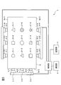
- FIG. 1 is a schematic block diagram of a spinning machine having a display device according to one embodiment of the present invention.
- FIG. 2 is a schematic internal block diagram of a spinning machine.
- FIG. 3 is a schematic block diagram of a display device according to an embodiment of the present invention.
- FIG. 4 is a diagram showing an example of the reference table.
- FIG. 5 is a schematic front view of the light guide plate.
- 6 is a schematic side cross-sectional view of the light guide plate in the line indicated by the arrow AA 'in
- FIG. 7 is a view showing an example of the relationship between a light source to be lit and a pattern to be displayed.
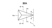
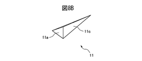
- FIG. 8A is a schematic front view of a prism.
- FIG. 8B is a schematic perspective view of a prism.
- FIG. 8C is a schematic side view of a prism.
- FIG. 8D is a schematic cross-sectional view of the prism along line BB 'in FIG. 8A.
- the display device includes a light guide plate formed in a plate shape of a material transparent to light emitted from the plurality of light sources, and the light guide plate is provided with a plurality of patterns. Further, in the display device, a plurality of light guide plates is formed as one light emission surface facing the player, and a plurality of side surfaces surrounding the light emission plate are in one-to-one correspondence with the plurality of patterns. It is formed as an incident surface facing the light source of.
- the display device can dynamically switch the pattern to be displayed.
- this display device associates and stores in advance the combination of the light sources to be lit among the plurality of light sources, and the lighting state number corresponding to the combination and one to one.
- the display device receives lighting control information including a lighting state number from a higher control device such as a control circuit of a gaming machine in which the display device is incorporated, a combination of light sources to be lit corresponding to the lighting state number is selected.
- a pattern corresponding to each of the light sources to be turned on is displayed.
- the side facing the player is referred to as the front, and the opposite side is referred to as the back.
- FIG. 1 is a schematic block diagram of a coin-operated game machine 100 having a display device according to an embodiment of the present invention.
- FIG. 2 is a schematic internal block diagram of the spinning machine 100.
- the spinning drum game machine 100 has a main body case 110 which is a game machine main body, a drum unit 120, a start lever 130, stop buttons 140a to 140c, and a display device 1.
- a control circuit 150 for controlling each unit of the main unit game machine 100
- a power supply circuit (not shown) for supplying power to each unit of the main unit game machine 100
- a medal storage and discharge mechanism (not shown) is provided for temporarily storing the medals in response to the control signal from the circuit 150 and discharging the medals.
- An opening 111 is formed at an upper central portion of the front surface of the main body housing 110, and a part of the drum unit 120 is visible through the opening 111. Further, on the upper surface of the lower frame 112 of the opening 111, a medal insertion slot 113 for inserting a medal is formed.
- the drum unit 120 has three drums 121-1 to 121-3.
- Each of the drums 121-1 to 121-3 responds to a control signal from the control circuit 150 and rotates about a rotation axis (not shown) substantially parallel and substantially horizontal to the front surface of the main body case 110 as a rotation center. It is possible to rotate separately.
- the surface of each of the drums 121-1 to 121-3 is divided into a plurality of areas having substantially the same width along the rotational direction, and various patterns are drawn for each area. Are visible to the player through the opening 111.
- the start lever 130 is provided on the left side of the front surface of the frame 112 of the main housing 110. Further, stop buttons 140a to 140c are provided substantially at the center of the front surface of the frame 112. The stop buttons 140a to 140c correspond to the drums 121-1 to 121-3, respectively.
- a medal discharge port 114 for discharging medals is formed at the lower part of the front surface of the main body case 110. And below the medal discharge port 114, a medal receptacle 115 for preventing the discharged medal from falling is attached.
- the control circuit 150 receives a signal indicating that the button has been pressed from the pressed button, and rotates the drum corresponding to the pressed button. Stop it.
- the control circuit 150 stops the drums of the drums 121-1 to 121-3 for which the corresponding stop button has not been pressed until the predetermined period has elapsed after the start of the rotation, after the predetermined period has elapsed. Let Then, when all the drums are stopped, if the same pattern is arranged in a line over all the drums, the control circuit 150 discharges a predetermined number of medals corresponding to the pattern through the medal discharge port 114.
- control circuit 150 controls the rotation state of the drums 121-1 to 121-3 (for example, the rotation speed of the individual drums, a state indicating rotation or stop), or the operation of the start lever 130 or the stop button 140a Lighting control information is generated in accordance with the game state corresponding to the operation of 140 c and the lighting control information is transmitted to the display device 1.
- the display device 1 is disposed on the front side of the drum unit 120 at the opening 111 of the main housing 110. Then, every time the display device 1 receives the lighting control information received from the control circuit 150, the display device 1 refers to the lighting state number included in the lighting control information to select one of the light sources of the display device 1 to be lighted. A combination is specified, and each light source specified by the specified combination is turned on to display a pattern corresponding to the light source. Therefore, the player can see the patterns drawn on the drums 121-1 to 121-3 and the patterns displayed on the display device 1 in an overlapping manner.
- FIG. 3 is a schematic block diagram of a display device according to an embodiment of the present invention.
- the display device 1 includes a light guide plate 2, light sources 3-1 to 3-9, collimating lenses 4-1 to 4-9, a storage unit 5, a communication unit 6, and a control unit 7.
- the light guide plate 2 is a member formed in a plate shape transparent to light emitted from each of the light sources 3-1 to 3-9.
- the light guide plate 2 is formed, for example, by molding a resin transparent to visible light, such as polymethyl methacrylate (PMMA), polycarbonate, or cycloolefin polymer.
- PMMA polymethyl methacrylate
- the light guide plate 2 is provided with nine patterns 21-1 to 21-9 which can be displayed by lighting of the light sources 3-1 to 3-9.
- the patterns 21-1 to 21-3 are arranged side by side along the rotational direction (vertical direction in FIG. 3) of the drum 121-1. Therefore, to the player, the displayed pattern among the patterns 21-1 to 21-3 appears to overlap with the pattern drawn on the drum 121-1.
- the patterns 21-4 to 21-6 are arranged side by side along the rotational direction of the drum 121-2. Therefore, the pattern displayed among the patterns 21-4 to 21-6 appears to the player overlapping the pattern drawn on the drum 12-2. Further, the patterns 21-7 to 21-9 are arranged side by side along the rotational direction of the drum 121-3. Therefore, to the player, the displayed pattern among the patterns 21-7 to 21-9 appears to overlap with the pattern drawn on the drum 121-3.
- the plurality of light sources 3-1 to 3-9 each have at least one light emitting element that emits visible light.
- the light sources 3-1, 3-4 and 3-8 are respectively one of the side surfaces of the light guide plate 2 and substantially parallel to the direction in which the drums 121-1 to 121-3 are arranged. Along the longitudinal direction of the incident surface 2a-1, it is disposed at substantially the same position as the position of the corresponding pattern in the longitudinal direction.
- the light emitting elements of the light sources 3-1, 3-4 and 3-8 are arranged such that the light emitting surfaces thereof face the light incident surface 2a-1.
- the light sources 3-3, 3-5, and 3-7 are side surfaces adjacent to the incident surface 2a-1 among the side surfaces of the light guide plate 2, respectively, and the incident surfaces substantially parallel to the rotational directions of the respective drums. Along the longitudinal direction of 2a-2, it is disposed at substantially the same position as the position of the corresponding pattern in the longitudinal direction.
- the light emitting elements of the light sources 3-3, 3-5 and 3-7 are arranged such that the light emitting surfaces thereof face the light incident surface 2a-2.
- the light sources 3-2, 3-6 and 3-9 are respectively along the longitudinal direction of the incident surface 2a-3 formed on the side opposite to the incident surface 2a-1 among the side surfaces of the light guide plate 2. It is arranged at substantially the same position as the position of the corresponding pattern in the longitudinal direction.
- the light emitting elements of each of the light sources 3-2, 3-6 and 3-9 are arranged such that the light emitting surfaces thereof face the incident surface 2a-3.
- the light sources 3-1 to 3-9 are turned on or off according to the control signal from the control unit 7, respectively.
- the light propagates along a direction substantially orthogonal to the incident plane of incidence, and propagates in the light guide plate 2 to form a plurality of patterns 21-k provided on the diffusion surface on the back side of the light guide plate 2. It is reflected by the prism and exits from the exit surface on the front side.
- the light emitting elements of the light sources 3-1 to 3-9 are, for example, light emitting diodes, incandescent lamps, or fluorescent lamps. And the luminescent color of each light source may be the same, or may mutually differ.
- the collimator lenses 4-1 to 4-9 are respectively disposed between the corresponding light source of the light sources 3-1 to 3-9 and the corresponding incident surface of the light guide plate 2, and the light emitted from the corresponding light source Parallelize. That is, the collimator lens 4-1 is disposed between the light source 3-1 and the incident surface 2a-1, and collimates the light emitted from the light emitting element of the light source 3-1. Similarly, the collimating lenses 4-4 and 4-8 are respectively disposed between the light sources 3-4 and 3-8 and the incident surface 2a-1, and emitted from the light emitting elements of the light sources 3-4 and 3-8. Collimated light.
- the collimator lens 4-3 is disposed between the light source 3-3 and the incident surface 2a-2, and collimates the light emitted from the light emitting element of the light source 3-3.
- the collimating lenses 4-5 and 4-7 are respectively disposed between the light sources 3-5 and 3-7 and the incident surface 2a-2, and emitted from the light emitting elements of the light sources 3-5 and 3-7. Collimated light.
- the collimator lens 4-2 is disposed between the light source 3-2 and the incident surface 2a-3, and collimates the light emitted from the light emitting element of the light source 3-3.
- the collimating lenses 4-6 and 4-9 are respectively disposed between the light sources 3-6 and 3-9 and the incident surface 2a-3, and emit light from the light emitting elements of the light sources 3-6 and 3-9. Collimated light.
- the collimator lenses 4-1 to 4-9 may be configured as refractive lenses, or may be configured as diffractive lenses such as Fresnel zone plates. Further, each of the collimator lenses 4-1 to 4-9 may be a cylindrical lens which collimates the light from the corresponding light source only in the longitudinal direction of the corresponding incident surface.
- the storage unit 5 has, for example, a volatile or non-volatile memory circuit. Then, the storage unit 5 stores a reference table or the like representing the correspondence between the lighting state number and the combination of the light sources to be lighted.
- the communication unit 6 has, for example, a communication interface and a communication circuit for communicating with the control circuit 150 of the drum game 100.
- the communication unit 6 is connected to the control circuit 150 via a signal line, receives various control information for controlling the display device 1 from the control circuit 150, and passes the control information to the control unit 7. For example, when receiving the lighting control information including the lighting state number, the communication unit 6 passes the lighting control information to the control unit 7.
- the control unit 7 includes, for example, a processor and drive circuits of the light sources 3-1 to 3-9.
- the control unit 7 stores, for example, the lighting state number included in the lighting control information and the storage unit 5 every time lighting control information is received from the control circuit 150 of the spinning machine 100 via the communication unit 6.
- the light source to be lighted is determined with reference to the reference table which has been set.
- the control unit 7 turns on the light source determined to be turned on among the light sources 3-1 to 3-9, and turns off the other light sources.
- the control unit 7 can cause the display device 1 to emit light and display a combination of patterns according to the lighting state number included in the lighting control information among the patterns 21-1 to 21-9.
- FIG. 4 is a diagram showing an example of the reference table.
- a lighting state number is shown in each column at the left end of the reference table 400.
- each of the columns L1 to L9 of the reference table 400 represents lighting / extinguishing of the light sources 3-1 to 3-9. Then, in each row of the reference table 400, it is indicated whether the light sources 3-1 to 3-9 are turned on or off with respect to the lighting state numbers indicated in the leftmost column.
- the light source 3-1 is turned on and the other light sources are turned off. Therefore, of the patterns 21-1 to 21-9, only the pattern 21-1 is displayed.
- the lighting state number is 'j'
- the light sources 3-2, 3-5 and 3-8 are turned on and the other light sources are turned off. Therefore, patterns 21-2, 21-5 and 21-8 are displayed.
- the lighting state number is 'n-1'
- all the light sources 3-1 to 3-9 are turned on. Therefore, all of the patterns 21-1 to 21-9 are displayed.
- the lighting state number is 'n', all the light sources 3-1 to 3-9 are turned off. Therefore, none of the patterns 21-1 to 21-9 is displayed.
- FIG. 5 is a schematic front view of the light guide plate 2.
- 6 is a schematic side sectional view of the light guide plate 2 taken along the line indicated by the arrow AA 'in FIG.
- three of the side surfaces of the light guide plate 2 are formed as incident surfaces 2a-1 to 2a-3.
- the lights emitted from the light sources 3-1, 3-4 and 3-8 enter the inside of the light guide plate 2 from the incident surface 2a-1.
- light emitted from the light sources 3-3, 3-5 and 3-7 is incident to the inside of the light guide plate 2 from the incident surface 2a-2.
- light emitted from the light sources 3-2, 3-6 and 3-9 is incident to the inside of the light guide plate 2 from the incident surface 2a-3.
- a plurality of prisms 11 for reflecting toward the player the light emitted from the corresponding light source and propagating in the light guide plate 2 are arranged along the patterns,
- the prism is formed on the diffusion surface 2 b located on the back side of the light guide plate 2. That is, the light from the light source 3-k propagated inside the light guide plate 2 is totally reflected by each of the plurality of prisms 11 arranged along the pattern 21-k, and then the light guide plate 2
- the light is emitted from the exit surface 2c which is located on the front side of the light emitting diode and faces the diffusion surface 2b.
- each of the prisms arranged along the pattern 21-k directs the light from the light source 3-k in a direction within a predetermined angle range based on the normal direction of the exit surface 2c of the light guide plate 2. To reflect. Therefore, while the light source 3-k is on, the player can observe the pattern 21-k which appears to emit light on the surface of the light guide plate 2.
- FIGS. 5 and 6 it should be noted that the size of each prism and the thickness of the light guide plate 2 are exaggerated in order to improve the viewability of the drawings.
- each of the prisms 11 forming the pattern is, for example, in a zigzag shape, a lattice shape, or random so that the arrangement density of the prisms becomes constant in the pattern Will be placed.
- the prisms 11 arranged in each pattern can have the same configuration except that the direction and the arrangement are different for each pattern.
- FIG. 8A is a schematic front view of the prism 11, and FIG. 8B is a schematic perspective view of the prism 11. And FIG. 8C is a schematic side view of the prism 11.
- FIG. 8D is a schematic cross-sectional view of the prism 11 along the line BB 'in FIG. 8A.
- the prism 11 is formed, for example, as a triangular pyramid shaped groove whose bottom surface is the diffusion surface 2 b. And one of the three slopes of the prism 11 is formed as a reflecting surface 11a which makes a predetermined angle with respect to the diffusing surface 2b.
- the predetermined angle is a method of totally reflecting the light from the corresponding light source (for example, light source 3-1 in the case of the prism forming the pattern 21-1) which is incident on the light guide plate 2, It is set to be directed to a direction within a predetermined angular range based on the line direction.
- the other two of the three inclined surfaces of the prism 11 are light from other than the corresponding light source (for example, in the case of the prism forming the pattern 21-1, the incident surface from the incident surface other than the incident surface 2a-1 And the direction out of the predetermined angle range based on the normal direction of the emitting surface 2 c so that the player can not visually recognize the light from the light sources 3-2 and 3-7 reaching the pattern 21-1). It is formed as diffusion surfaces 11 b and 11 c that are reflected toward the side.
- each of the prisms 11 forming the pattern 21-k is from the light source 3-k such that the reflecting surface 11a faces the light source 3-k, that is, in a plane parallel to the diffusion surface 2b. It is arrange
- each of the prisms forming the pattern 21-1 is disposed such that the reflection surface 11a faces the light source 3-1 (that is, the reflection surface 11a is substantially parallel to the incident surface 2a-1). .
- light emitted from the light source 3-k enters the light guide plate 2 and travels to any of the prisms forming the pattern 21-k is reflected by the reflection surface 11a of the prism, and the front side of the light guide plate 2
- the light guide plate 2 is emitted from the emission surface 2c toward the player located in
- light emitted from a light source other than the light source 3-k and incident on the light guide plate 2 and directed to any of the prisms forming the pattern 21-k is visible to the player by the diffusion surface 11b or 11c of the prism
- the light is reflected toward a direction out of a predetermined angle range based on the normal direction of the light exit surface 2 c of the light guide plate 2.
- the direction in which light emitted from a light source other than the light source 3-k and incident into the light guide plate 2 is reflected by the diffusion surface 11b or 11c of the prism forming the pattern corresponding to the light source 3-k is the light source 3
- the direction orthogonal to the propagation direction of light from -k (for example, for the prism forming the pattern 21-1, the direction orthogonal to the propagation direction of light from the light source 3-1, parallel to the incident surface 2a-1)
- the diffusion surface 11b or 11c of the prism hereinafter referred to as a rotation angle for convenience
- the angle formed by the reflected light with respect to the normal direction of the exit surface 2 c when emitted from the light guide plate 2 is influenced by the refractive index of the material forming the
- the predetermined angle range based on the direction in which the player is located that is, the normal direction of the exit surface 2c of the light guide plate 2 is within 30 ° from the normal direction of the exit surface 2c of the light guide plate 2.
- the light guide plate 2 is formed of polycarbonate (refractive index 1.59) or PMMA (refractive index 1.49)
- the rotation angle ⁇ is in the range of 25 ° to 65 °
- the inclination angle ⁇ is in the range of 25 ° to 55 °.
- each prism 11 is formed.
- the predetermined angle range based on the normal direction of the exit surface 2 c of the light guide plate 2 is within 45 ° from the normal direction of the exit surface 2 c of the light guide plate 2.
- the rotation angle ⁇ Is preferably in the range of 35.degree. To 55.degree.
- the inclination angle .alpha. Is in the range of 25.degree. To 55.degree.
- the predetermined angle range based on the normal direction of the exit surface 2 c of the light guide plate 2 is within 60 ° from the normal direction of the exit surface 2 c of the light guide plate 2.
- the rotation angle ⁇ Is preferably in the range of 40.degree. To 50.degree.
- the rotation angle and the inclination angle of each diffusion surface of each prism 11 in any pattern may be set similarly.
- the light guide plate is provided with a plurality of patterns formed by the arrangement of the prisms, and the patterns are displayed by causing the light sources corresponding to the respective patterns to emit light.
- the display device corresponds to the lighting state number included in the received lighting control information with reference to a reference table in which the combination of the light sources to be lighted, that is, the combination of the patterns to be displayed and the lighting state number is associated. Identify the combination of light sources to be lit. Therefore, since it is only necessary to designate the lighting state number when dynamically switching the pattern to be displayed, this display device can simplify the switching of the pattern to be displayed. As a result, the control load on the switching of the pattern to be displayed is reduced for the control circuit of the gaming machine in which the display device is incorporated.
- the collimating lens may be omitted.
- each light source has one light emitting element. Then, light emitted from each light source is incident into the light guide plate 2 through an incident surface facing the light source. The incident light spreads in a direction parallel to the incident plane of incidence as it propagates in the light guide plate 2.
- each prism 11 forming the pattern faces the light source corresponding to the reflecting surface 11a, that is, on a plane parallel to the diffusion surface 2b of the light guide plate 2, It is preferable that the reflecting surface 11 a be formed along an arc centered on the corresponding light source. Thereby, each prism 11 positions the light emitted from the corresponding light source and incident into the light guide plate 2 within a predetermined angle range on the front side of the light guide plate 2 with respect to the normal direction of the exit surface 2 c.
- the reference table stored in the storage unit 5 is a combination of two or more of the lighting state number, the light source to be lit, and at least one of the plurality of lighting state numbers.
- the correspondence with the order in which each of the combinations is applied may be expressed.
- the control unit 7 refers to the reference table to specify the combination of two or more of the light sources to be lit and the application order of the individual combinations corresponding to the notified lighting state number, and the specified application According to the order, for example, the combination of the specified light sources to be turned on may be switched at predetermined intervals. Therefore, according to this modification, the display device can dynamically switch the combination of patterns to be displayed by being notified of only one lighting state number, so it is easier to switch the combination of patterns to be displayed. Can be
- the lighting control information may include information specifying a cycle of switching a combination of light sources to be lit.
- the control unit 7 may switch the combination of the light sources to be lit according to the application order for each cycle designated by the information.
- the display device can simplify the switching of the combination of patterns to be displayed and the control of the switching cycle.
- the number of patterns provided on the light guide plate is not limited to nine, and may be two or more. Further, each of the plurality of patterns provided on the light guide plate may partially overlap each other. Furthermore, the light guide plate may be formed to be curved in an arc shape along the outer periphery of each drum of the drum unit.
- the gaming machine having the display according to the above embodiment or modification may have another display such as a liquid crystal display instead of the drum unit.
- the gaming machine having the display device according to the above embodiment or modification may be a ball game machine.
- SYMBOLS 1 display apparatus 2 light-guide plate 2a-1 to 2a-3 entrance plane 2b diffusion plane 2c exit plane 3-1 to 3-9 light source 11 prism 11a reflection plane 11b, 11c diffusion plane 21-1 to 21-9 pattern 4, 4 -1 to 4-9 Collimate lens 5 Storage unit 6 Communication unit 7 Control unit 100 Rotating gaming machine 110 Main unit case 120 Drum unit 130 Start lever 140a to 140c Stop button 150 Control circuit 111 Opening 112 Frame 113 Medal slot 114 Exit 115 medal receiver
Landscapes
- Physics & Mathematics (AREA)
- General Physics & Mathematics (AREA)
- Optics & Photonics (AREA)
- Engineering & Computer Science (AREA)
- Theoretical Computer Science (AREA)
- Multimedia (AREA)
- Slot Machines And Peripheral Devices (AREA)
- Pinball Game Machines (AREA)
- Illuminated Signs And Luminous Advertising (AREA)
Abstract
表示装置は、複数のパターン(21-1~21-9)を表示可能であり、かつ、入射面を有する導光板2と、入射面と対向するように配置され、かつ、複数のパターンのそれぞれに対応する複数の光源(3-1~3-9)と、複数の点灯状態番号のそれぞれについて、その点灯状態番号と点灯する光源の組み合わせとの関係を表す参照テーブルを記憶する記憶部5と、参照テーブルを参照して、点灯制御情報に含まれる点灯状態番号に対応する、点灯する光源の組み合わせを特定し、特定した光源の組み合わせに従って各光源の点灯及び消灯を制御する制御部7とを有する。導光板2は、その一方の面に、各パターンに沿って配列され、そのパターンに対応する光源から発して入射面から導光板内に入射した光を導光板の他方の面へ向けて反射する複数のプリズムを有する。
Description
本発明は、表示されるパターンを切り替え可能な表示装置、及び、そのような表示装置を有する遊技機に関する。
従来より、複数の光源のうちの点灯する光源に応じて表示させるパターンを動的に切り替えることを可能とする技術が提案されている(例えば、特許文献1を参照)。
例えば、特許文献1に開示された表示装置は、複数のパターンを表示可能な導光板と、導光板の側壁の一辺に沿って並べて配置される複数の光源と、点灯順序情報に従って複数の光源の点灯及び消灯を制御する制御部とを有する。導光板は、その一方の面において、パターンごとに、そのパターンに沿って配列され、複数の光源のうち、そのパターンに対応する光源から発して導光板の入射面から導光板内に入射した可視光を導光板の他方の面へ向けて反射する複数のプリズムを有する。
特許文献1に開示された表示装置は、点灯順序情報に従って複数の光源の点灯及び消灯を制御することで、表示するパターンを順次切り替えることができる。しかし、この表示装置では、上位の制御装置が点灯順序情報を生成して表示装置へ通知することとなるので、各光源の点灯順序を変更する場合などには、上位の制御装置が個々の光源の点灯順序に合わせて点灯順序情報を生成することになり、上位の制御装置の負荷が大きくなる。そこで、表示するパターンを切り替えるための制御を簡単化できる表示装置が求められている。
そこで、本発明は、表示するパターンを切り替えるための制御を簡単化することが可能な表示装置を提供することを目的とする。
本発明の一つの形態として、表示装置が提供される。この表示装置は、透明な部材で形成され、複数のパターンを表示可能であり、かつ、入射面を有する導光板と、入射面と対向するように配置され、かつ、複数のパターンのそれぞれに対応する複数の光源と、複数の点灯状態番号のそれぞれについて、その点灯状態番号と、複数の光源のうちの点灯する光源の組み合わせとの関係を表す参照テーブルを記憶する記憶部と、複数の点灯状態番号のうちの何れかを含む点灯制御情報を受信する通信部と、参照テーブルを参照して、点灯制御情報に含まれる点灯状態番号に対応する、複数の光源のうち点灯する光源の組み合わせを特定し、特定した光源の組み合わせに従って複数の光源の点灯及び消灯を制御する制御部とを有する。そして導光板は、その一方の面に、複数のパターンのそれぞれについて、そのパターンに沿って配列され、複数の光源のうち、そのパターンに対応する光源から発して入射面から導光板内に入射した光を導光板の他方の面へ向けて反射する複数のプリズムを有する。
この表示装置において、参照テーブルは、複数の点灯状態番号の少なくとも一つについて、その点灯状態番号と、2以上の点灯する光源の組み合わせ及びその2以上の点灯する光源の組み合わせのうちの適用される順序との関係を表し、制御部は、参照テーブルを参照して、点灯制御情報に含まれるその少なくとも一つの点灯状態番号に対応する、2以上の点灯する光源の組み合わせ及び適用される順序を特定し、特定した2以上の点灯する光源の組み合わせ及び適用される順序に従って複数の光源の点灯及び消灯を制御することが好ましい。
本発明の他の形態として、遊技機が提供される。この遊技機は、遊技機本体と、遊技機本体の遊技者と対向する側の面に設けられた表示装置と、遊技の状態に従って、複数の点灯状態番号の何れかを含む点灯制御情報を生成し、生成した点灯制御情報を表示装置へ送信する制御回路とを有する。表示装置は、透明な部材で形成され、複数のパターンを表示可能であり、かつ、入射面を有する導光板と、入射面と対向するように配置され、かつ、複数のパターンのそれぞれに対応する複数の光源と、複数の点灯状態番号のそれぞれについて、点灯状態番号と、複数の光源のうちの点灯する光源の組み合わせとの関係を表す参照テーブルを記憶する記憶部と、点灯制御情報を受信する通信部と、参照テーブルを参照して、点灯制御情報に含まれる点灯状態番号に対応する、複数の光源のうち点灯する光源の組み合わせを特定し、特定した光源の組み合わせに従って複数の光源の点灯及び消灯を制御する制御部とを有する。そして導光板は、その一方の面に、複数のパターンのそれぞれについて、そのパターンに沿って配列され、複数の光源のうち、そのパターンに対応する光源から発して入射面から導光板内に入射した光を導光板の他方の面へ向けて反射する複数のプリズムを有する。
本発明に係る表示装置は、表示するパターンを切り替えるための制御を簡単化することができるという効果を奏する。
以下、本発明の実施形態による表示装置を、図を参照しつつ説明する。この表示装置は、複数の光源が発する光に対して透明な材料を板状に形成した導光板を有し、その導光板に、複数のパターンが設けられる。また、この表示装置において、導光板の一方の面が遊技者に面する出射面として形成され、導光板の出射面を囲う周囲の側面が、複数のパターンのそれぞれと1対1に対応する複数の光源と対向する入射面として形成される。そして出射面と対向する導光板の他方の面には、複数のパターンのそれぞれごとに、複数の光源のうちの対応する光源から発し、導光板内に入射した光を出射面へ向けて反射する複数のプリズムがそのパターンに沿って配列される。したがって、点灯する光源を切り替えることで、この表示装置は、表示するパターンを動的に切り替えることができる。
さらに、この表示装置は、予め、複数の光源のうちの点灯させる光源の組み合わせと、その組み合わせと1対1に対応する点灯状態番号とを関連付けて記憶する。そしてこの表示装置は、表示装置が組み込まれる遊技機の制御回路といった、上位の制御装置から、点灯状態番号を含む点灯制御情報を受信すると、その点灯状態番号に対応する、点灯させる光源の組み合わせを特定し、特定した組み合わせで指定される各光源を点灯させることで、点灯させる光源のそれぞれに対応するパターンを表示する。
なお、以下では、説明の便宜上、遊技者と対向する側を正面とし、その反対側を背面とする。
なお、以下では、説明の便宜上、遊技者と対向する側を正面とし、その反対側を背面とする。
図1は、本発明の一つの実施形態に係る表示装置を有する回胴遊技機100の概略構成図である。また図2は、回胴遊技機100の概略内部構成図である。図1に示すように、回胴遊技機100は、遊技機本体である本体筐体110と、ドラムユニット120と、スタートレバー130と、ストップボタン140a~140cと、表示装置1とを有する。
また回胴遊技機100は、本体筐体110内に、回胴遊技機100の各部を制御する制御回路150、回胴遊技機100の各部に電力を供給する電源回路(図示せず)及び制御回路150からの制御信号に応じてメダルを一時貯留し、かつメダルを排出するためのメダル貯留及び排出機構(図示せず)を有する。
また回胴遊技機100は、本体筐体110内に、回胴遊技機100の各部を制御する制御回路150、回胴遊技機100の各部に電力を供給する電源回路(図示せず)及び制御回路150からの制御信号に応じてメダルを一時貯留し、かつメダルを排出するためのメダル貯留及び排出機構(図示せず)を有する。
本体筐体110の前面の中央上部には開口111が形成されており、その開口111を通じて、ドラムユニット120の一部が視認可能になっている。また開口111の下側の枠112の上面には、メダルを投入するためのメダル投入口113が形成されている。
ドラムユニット120は、3個のドラム121-1~121-3を有する。ドラム121-1~121-3は、制御回路150からの制御信号に応じて、本体筐体110の前面に対して略平行かつ略水平な回転軸(図示せず)を回転中心として、それぞれ、別個に回転可能となっている。ドラム121-1~121-3の表面は、それぞれ、回転方向に沿って複数の略同一幅を持つ領域に区切られ、領域ごとに様々なパターンが描かれており、それら領域のうちの一部が開口111を介して遊技者に視認可能となっている。
スタートレバー130は、本体筐体110の枠112の前面に向かって左側に設けられている。また、枠112の前面略中央には、ストップボタン140a~140cが設けられている。ストップボタン140a~140cは、それぞれ、ドラム121-1~121-3に対応する。
本体筐体110の前面の下部には、メダルを排出するためのメダル排出口114が形成されている。そしてメダル排出口114の下方には、排出されたメダルが落下することを防止するためのメダル受け皿115が取り付けられている。
メダルがメダル投入口113に投入された後に、スタートレバー130が操作されると、スタートレバー130が操作されたことを示す信号が制御回路150へ伝達される。そして制御回路150は、ドラム121-1~121-3の回転を開始させる。
その後、ストップボタン140a~140cの何れかが押下されると、制御回路150は、その押下されたボタンから押下されたことを示す信号を受信し、その押下されたボタンに対応するドラムの回転を停止させる。あるいは、制御回路150は、ドラム121-1~121-3のうち、回転を開始してから所定期間が経過するまでに、対応するストップボタンが押下されなかったドラムを、その所定期間経過後に停止させる。
そして全てのドラムが停止した時点で、同一のパターンが全てのドラムにわたって一列に並んでいると、制御回路150は、そのパターンに応じた所定枚数のメダルをメダル排出口114を通じて排出する。
そして全てのドラムが停止した時点で、同一のパターンが全てのドラムにわたって一列に並んでいると、制御回路150は、そのパターンに応じた所定枚数のメダルをメダル排出口114を通じて排出する。
また、制御回路150は、ドラム121-1~121-3の回転状態(例えば、個々のドラムの回転速度、回転中あるいは回転停止などを表す状態)、スタートレバー130の操作、またはストップボタン140a~140cの操作などに応じた遊技状態にしたがって、点灯制御情報を生成し、その点灯制御情報を表示装置1へ送信する。
表示装置1は、本体筐体110の開口111において、ドラムユニット120の正面側に配置されている。そして表示装置1は、制御回路150から受信した点灯制御情報を受信する度に、点灯制御情報に含まれる点灯状態番号を参照して、表示装置1が有する複数の光源のうち、点灯させる光源の組み合わせを特定し、特定された組み合わせで指定される各光源を点灯させることで、その光源に対応するパターンを表示する。したがって、遊技者からは、ドラム121-1~121-3に描かれたパターンと、表示装置1に表示されたパターンとが重複して見えるようになる。
次に、表示装置1について詳細に説明する。
図3は、本発明の一つの実施形態に係る表示装置の概略構成図である。表示装置1は、導光板2と、光源3-1~3-9と、コリメートレンズ4-1~4-9と、記憶部5と、通信部6と、制御部7とを有する。
図3は、本発明の一つの実施形態に係る表示装置の概略構成図である。表示装置1は、導光板2と、光源3-1~3-9と、コリメートレンズ4-1~4-9と、記憶部5と、通信部6と、制御部7とを有する。
導光板2は、各光源3-1~3-9から発する光に対して透明な板状に形成された部材である。導光板2は、例えば、ポリメチルメタクリレート(PMMA)、ポリカーボネート、シクロオレフィンポリマーといった、可視光に対して透明な樹脂を成型することで形成される。そして導光板2には、光源3-1~3-9の点灯によって表示可能な9個のパターン21-1~21-9が設けられる。
この例では、パターン21-1~21-3が、ドラム121-1の回転方向(図3では、縦方向)に沿って並べて配置される。したがって、遊技者からは、パターン21-1~21-3のうち、表示されるパターンが、ドラム121-1に描かれたパターンに重複して見えることになる。
同様に、パターン21-4~21-6が、ドラム121-2の回転方向に沿って並べて配置される。したがって、遊技者からは、パターン21-4~21-6のうち、表示されるパターンが、ドラム121-2に描かれたパターンに重複して見えることになる。さらに、パターン21-7~21-9が、ドラム121-3の回転方向に沿って並べて配置される。したがって、遊技者からは、パターン21-7~21-9のうち、表示されるパターンが、ドラム121-3に描かれたパターンに重複して見えることになる。
導光板2は、光源3-k(k=1、2、・・・、9)が点灯している間、光源3-kからの光をその内部で伝搬させるとともに、背面側に形成された、光源3-kに対応し、パターン21-kを形成するように配列された複数のプリズム(詳細は後述)により、その光を正面側において出射面の法線方向を基準とする所定の角度範囲内に位置する遊技者へ向けて反射させることで、遊技者が発光するパターン21-kを視認できるようにする。
なお、導光板2の詳細については後述する。
なお、導光板2の詳細については後述する。
複数の光源3-1~3-9は、それぞれ、可視光を発する少なくとも一つの発光素子を有する。本実施形態では、光源3-1、3-4及び3-8は、それぞれ、導光板2の側面のうちの一つであり、かつ、ドラム121-1~121-3の並び方向と略平行な入射面2a-1の長手方向に沿って、その長手方向における対応するパターンの位置と略同じ位置に配置される。そして光源3-1、3-4及び3-8のそれぞれが有する各発光素子は、その発光面が入射面2a-1と対向するように配置される。
同様に、光源3-3、3-5及び3-7は、それぞれ、導光板2の側面のうち、入射面2a-1と隣接する側面であり、各ドラムの回転方向と略平行な入射面2a-2の長手方向に沿って、その長手方向における対応するパターンの位置と略同じ位置に配置される。そして光源3-3、3-5及び3-7のそれぞれが有する各発光素子は、その発光面が入射面2a-2と対向するように配置される。
また、光源3-2、3-6及び3-9は、それぞれ、導光板2の側面のうち、入射面2a-1と反対側の側面に形成される入射面2a-3の長手方向に沿って、その長手方向における対応するパターンの位置と略同じ位置に配置される。そして光源3-2、3-6及び3-9のそれぞれが有する各発光素子は、その発光面が入射面2a-3と対向するように配置される。
また、光源3-2、3-6及び3-9は、それぞれ、導光板2の側面のうち、入射面2a-1と反対側の側面に形成される入射面2a-3の長手方向に沿って、その長手方向における対応するパターンの位置と略同じ位置に配置される。そして光源3-2、3-6及び3-9のそれぞれが有する各発光素子は、その発光面が入射面2a-3と対向するように配置される。
光源3-1~3-9は、それぞれ、制御部7からの制御信号に応じて点灯または消灯する。そして制御部7が光源3-k(k=1、2、・・・、9)を点灯させている間、光源3-kから発した光は、コリメートレンズ4-kにより平行光化された後、入射面2a-1~2a-3のうちの対応する入射面を介して導光板2内に入射する。その光は、入射した入射面と略直交する方向に沿って伝播し、導光板2内を伝搬した後に導光板2の背面側の拡散面に設けられた、パターン21-kを形成する複数のプリズムで反射されて正面側の出射面から出射する。
なお、光源3-1~3-9が有する発光素子は、例えば、発光ダイオード、白熱灯あるいは蛍光灯である。そして各光源の発光色は同じであってもよく、あるいは、互いに異なっていてもよい。
コリメートレンズ4-1~4-9は、それぞれ、光源3-1~3-9のうちの対応する光源と導光板2の対応する入射面との間に配置され、対応する光源から発した光を平行光化する。すなわち、コリメートレンズ4-1は、光源3-1と入射面2a-1の間に配置され、光源3-1が有する発光素子から発した光を平行光化する。同様に、コリメートレンズ4-4及び4-8は、それぞれ、光源3-4及び3-8と入射面2a-1の間に配置され、光源3-4及び3-8が有する発光素子から発した光を平行光化する。
また、コリメートレンズ4-3は、光源3-3と入射面2a-2の間に配置され、光源3-3が有する発光素子から発した光を平行光化する。同様に、コリメートレンズ4-5及び4-7は、それぞれ、光源3-5及び3-7と入射面2a-2の間に配置され、光源3-5及び3-7が有する発光素子から発した光を平行光化する。
さらに、コリメートレンズ4-2は、光源3-2と入射面2a-3の間に配置され、光源3-3が有する発光素子から発した光を平行光化する。同様に、コリメートレンズ4-6及び4-9は、それぞれ、光源3-6及び3-9と入射面2a-3の間に配置され、光源3-6及び3-9が有する発光素子から発した光を平行光化する。
これにより、各光源からの光が、同一の入射面に沿ってその光源と並べて配置される他の光源に対応するパターンを照射することが抑制される。例えば、光源3-1から発した光が、光源3-4及び3-8に対応するパターン21-4及び21-8を照射することが抑制される。
なお、コリメートレンズ4-1~4-9は、屈折レンズとして構成されてもよく、あるいは、フレネルゾーンプレートといった回折レンズとして構成されてもよい。また、コリメートレンズ4-1~4-9は、それぞれ、対応する光源からの光を、対応する入射面の長手方向についてのみ平行光化するシリンドリカルレンズであってもよい。
なお、コリメートレンズ4-1~4-9は、屈折レンズとして構成されてもよく、あるいは、フレネルゾーンプレートといった回折レンズとして構成されてもよい。また、コリメートレンズ4-1~4-9は、それぞれ、対応する光源からの光を、対応する入射面の長手方向についてのみ平行光化するシリンドリカルレンズであってもよい。
記憶部5は、例えば、揮発性あるいは不揮発性のメモリ回路を有する。そして記憶部5は、点灯状態番号と点灯させる光源の組み合わせとの対応関係を表す参照テーブルなどを記憶する。
通信部6は、例えば、回胴遊技機100の制御回路150と通信するための通信インターフェース及び通信回路を有する。そして通信部6は、信号線を介して制御回路150と接続され、制御回路150から、表示装置1を制御するための各種制御情報を受信し、その制御情報を制御部7へわたす。例えば、通信部6は、点灯状態番号を含む点灯制御情報を受信すると、点灯制御情報を制御部7へわたす。
制御部7は、例えば、プロセッサと、光源3-1~3-9の駆動回路とを有する。そして制御部7は、例えば、回胴遊技機100の制御回路150から通信部6を介して点灯制御情報を受信する度に、その点灯制御情報に含まれる点灯状態番号と、記憶部5に記憶されている参照テーブルとを参照して、光源3-1~3-9のうち、点灯させる光源を決定する。そして制御部7は、光源3-1~3-9のうち、点灯させることを決定した光源を点灯させ、他の光源を消灯する。これにより、制御部7は、パターン21-1~21-9のうち、点灯制御情報に含まれる点灯状態番号に応じたパターンの組み合わせを、表示装置1に発光表示させることができる。
図4は、参照テーブルの一例を示す図である。参照テーブル400の左端の各欄には、点灯状態番号が示される。また、参照テーブル400のL1~L9の列のそれぞれは、光源3-1~3-9の点灯・消灯を表す。そして参照テーブル400の各行には、左端の欄に示された点灯状態番号に対して、光源3-1~3-9が点灯するか消灯するかが表される。
例えば、点灯状態番号が'1'であれば、光源3-1が点灯され、その他の光源が消灯される。したがって、パターン21-1~21-9のうち、パターン21-1のみが表示される。また、点灯状態番号が'j'であれば、光源3-2、3-5及び3-8が点灯され、その他の光源が消灯される。したがって、パターン21-2、21-5及び21-8が表示される。さらに、点灯状態番号が'n-1'であれば、光源3-1~3-9の全てが点灯される。したがって、パターン21-1~21-9の全てが表示される。さらにまた、点灯状態番号が'n'であれば、光源3-1~3-9の全てが消灯される。したがって、パターン21-1~21-9の何れも表示されない。
以下、導光板2の詳細について説明する。
図5は、導光板2の概略正面図である。また図6は、図5の矢印AA’で示される線における、導光板2の概略側面断面図である。図5及び図6に示されるように、導光板2の側面のうちの三つは、入射面2a-1~2a-3として形成される。上記のように、光源3-1、3-4及び3-8から発した光は入射面2a-1から導光板2の内部に入射する。また、光源3-3、3-5及び3-7から発した光は入射面2a-2から導光板2の内部に入射する。さらに、光源3-2、3-6及び3-9から発した光は入射面2a-3から導光板2の内部に入射する。
パターン21-1~21-9のそれぞれについて、対応する光源から発して導光板2内を伝搬する光を遊技者側へ向けて反射する複数のプリズム11が、そのパターンに沿って配列され、各プリズムは、導光板2の背面側に位置する拡散面2bに形成される。すなわち、導光板2の内部を伝搬した、光源3-kからの光は、複数のプリズム11のうち、パターン21-kに沿って配列される各プリズムにて全反射された後、導光板2の正面側に位置し、かつ、拡散面2bと対向する出射面2cから出射する。その際、パターン21-kに沿って配列される各プリズムは、光源3-kからの光を、導光板2の出射面2cの法線方向を基準とする所定の角度範囲内の方向に向けて反射する。したがって、遊技者は、光源3-kが点灯している間、導光板2の表面において発光して見えるパターン21-kを観察できる。なお、図5及び図6において、図の見易さの向上のために、各プリズムのサイズ及び導光板2の厚さは誇張されている点に留意されたい。
図7は、点灯する光源と表示されるパターンの関係の一例を示す図である。図7に示されるように、光源3-k(k=1、2、・・・、9)が点灯し、他の光源が消灯していると、パターン21-kが表示され、他のパターンが視認不能となる。
パターン21-1~21-9のそれぞれについて、そのパターンを形成する各プリズム11は、例えば、そのパターン内において千鳥足状、格子状あるいは、プリズムの配置密度がそのパターン内で一定となるようにランダムに配置される。
なお、各パターンに配列されるプリズム11は、パターンごとに向き及び配置が異なるだけで同じ構成とすることができる。
図8Aは、プリズム11の概略正面図であり、図8Bは、プリズム11の概略斜視図である。そして図8Cは、プリズム11の概略側面図である。また、図8Dは、図8Aにおける線BB’に沿った、プリズム11の概略断面図である。プリズム11は、例えば、拡散面2bを底面とする三角錐状の溝として形成される。そしてプリズム11の3個の斜面のうちの一つは、拡散面2bに対して所定の角度をなす反射面11aとして形成される。なお、所定の角度は、導光板2へ入射した、対応する光源(例えば、パターン21-1を形成するプリズムの場合、光源3-1)からの光を全反射させて、出射面2cの法線方向を基準とする所定の角度範囲内の方向へ向けるように設定される。また、プリズム11の3個の斜面のうちの他の二つは、対応する光源以外からの光(例えば、パターン21-1を形成するプリズムの場合、入射面2a-1以外の入射面から入射し、かつ、パターン21-1に達する、光源3-2及び3-7からの光)を遊技者が視認できないように、出射面2cの法線方向を基準とする所定の角度範囲外の方向へ向けて反射させる拡散面11b、11cとして形成される。
再度図5を参照すると、パターン21-kを形成する各プリズム11は、反射面11aが光源3-kと正対するように、すなわち、拡散面2bと平行な面において、光源3-kからの光が入射する入射面と反射面11aとが略平行となるように配置される。例えば、パターン21-1を形成する各プリズムは、その反射面11aが光源3-1と正対するように(すなわち、反射面11aが入射面2a-1と略平行となるように)配置される。
これにより、光源3-kから発して導光板2内に入射し、パターン21-kを形成する何れかのプリズムへ向かう光は、そのプリズムの反射面11aにより反射され、導光板2の正面側に位置する遊技者へ向けて出射面2cから導光板2を出射する。一方、光源3-k以外の光源から発して導光板2内に入射し、パターン21-kを形成する何れかのプリズムへ向かう光は、そのプリズムの拡散面11bまたは11cにより、遊技者に視認されないように、導光板2の出射面2cの法線方向を基準とする所定の角度範囲外の方向へ向けて反射される。
ここで、光源3-k以外の光源から発して導光板2内に入射した光が、光源3-kに対応するパターンを形成するプリズムの拡散面11bまたは11cにより反射される方向は、光源3-kからの光の伝搬方向と直交する方向(例えば、パターン21-1を形成するプリズムについては、光源3-1からの光の伝搬方向と直交する、入射面2a-1と平行な方向)とプリズムの拡散面11bまたは11cとがなす角(以下、便宜上、回転角と呼ぶ)θと、導光板2の拡散面2bとプリズムの拡散面11bまたは11cとがなす角度(以下、便宜上、傾斜角と呼ぶ)αの組み合わせで決定される。さらに、その反射された光が導光板2から出射する際の出射面2cの法線方向に対してなす角度は、導光板2を形成する材料の屈折率により影響される。
例えば、遊技者が位置する方向、すなわち、導光板2の出射面2cの法線方向を基準とする所定の角度範囲が導光板2の出射面2cの法線方向から30°以内であるとする。この場合において、導光板2がポリカーボネート(屈折率1.59)またはPMMA(屈折率1.49)で形成される場合、対応する光源以外の光源から発してプリズム11により反射された光が遊技者へ向かわないように、その反射光を所定の角度範囲外の方向へ向けるためには、回転角θは25°~65°の範囲内となり、かつ、傾斜角αは25°~55°の範囲内となるように、各プリズム11は形成されることが好ましい。
また、導光板2の出射面2cの法線方向を基準とする所定の角度範囲が導光板2の出射面2cの法線方向から45°以内であるとする。この場合において、導光板2がポリカーボネートまたはPMMAで形成される場合、対応する光源以外の光源から発してプリズム11により反射された光を所定の角度範囲外の方向へ向けるためには、回転角θは35°~55°の範囲内となり、かつ、傾斜角αは25°~55°の範囲内となるように、各プリズム11は形成されることが好ましい。
さらに、導光板2の出射面2cの法線方向を基準とする所定の角度範囲が導光板2の出射面2cの法線方向から60°以内であるとする。この場合において、導光板2がポリカーボネートまたはPMMAで形成される場合、対応する光源以外の光源から発してプリズム11により反射された光を所定の角度範囲外の方向へ向けるためには、回転角θは40°~50°の範囲内となり、かつ、傾斜角αは25°~55°の範囲内となるように、各プリズム11は形成されることが好ましい。
なお、何れのパターン内の各プリズム11の各拡散面の回転角及び傾斜角についても、同様に設定されればよい。
以上に説明してきたように、この表示装置では、導光板に、プリズムの配列によって形成される複数のパターンが設けられ、各パターンに対応する光源を発光させることで、そのパターンが表示される。そしてこの表示装置は、点灯する光源の組み合わせ、すなわち、表示するパターンの組み合わせと、点灯状態番号とを関連付けた参照テーブルを参照して、受信した点灯制御情報に含まれる点灯状態番号に対応する、点灯する光源の組み合わせを特定する。したがって、表示するパターンを動的に切り替える際に点灯状態番号だけが指定されればよいので、この表示装置は、表示するパターンの切り替えを簡単化できる。その結果として、この表示装置が組み込まれる遊技機の制御回路についての、表示するパターンの切り替えに関する制御負荷が軽減される。
変形例によれば、コリメートレンズは省略されてもよい。この変形例では、各光源は、一つの発光素子を有する。そして各光源から発した光は、それぞれ、その光源と対向する入射面を介して導光板2内に入射する。入射した光は、導光板2内を伝搬するにつれて、入射した入射面に平行な方向において拡がる。
したがって、この変形例では、各パターンについて、そのパターンを形成する各プリズム11は、反射面11aが対応する光源と正対するように、すなわち、導光板2の拡散面2bに平行な面上で、対応する光源を中心とする円弧に沿って反射面11aが位置するように形成されることが好ましい。これにより、各プリズム11は、対応する光源から発して導光板2内に入射した光を、導光板2の正面側において、出射面2cの法線方向を基準とする所定の角度範囲内に位置する遊技者の方へ向けて反射することができる。一方、対応する光源以外の光源から発して導光板2内に入射した光については、各プリズム11の拡散面11bまたは11cにより反射され、遊技者が位置する方向とは異なる方向、すなわち、出射面2cの法線方向を基準とする所定の角度範囲外の方向へ向けられる。
他の変形例によれば、記憶部5が記憶する参照テーブルは、複数の点灯状態番号のうちの少なくとも一つについて、その点灯状態番号と、点灯する光源の2以上の組み合わせ及びその2以上の組み合わせのそれぞれが適用される順序との対応関係を表してもよい。この場合には、制御部7は、参照テーブルを参照して、通知された点灯状態番号に対応する、点灯する光源の2以上の組み合わせ及び個々の組み合わせの適用順序を特定し、その特定した適用順序に従って、例えば、一定周期ごとに、特定した点灯する光源の組み合わせを切り替えればよい。したがって、この変形例によれば、表示装置は、一つの点灯状態番号が通知されるだけで、表示するパターンの組み合わせを動的に切り替えることができるので、表示するパターンの組み合わせの切り替えをより簡単化できる。
さらに、上記の変形例において、点灯制御情報には、点灯する光源の組み合わせを切り替える周期を指定する情報が含まれてもよい。制御部7は、その情報で指定された周期ごとに、適用順序に従って点灯する光源の組み合わせを切り替えればよい。これにより、表示装置は、表示するパターンの組み合わせの切り替えと切替の周期の制御を簡単化できる。
さらに他の変形例によれば、導光板に設けられるパターンの数は9個に限られず、2個以上であればよい。また、導光板に設けられる複数のパターンのそれぞれは、互いに部分的に重なっていてもよい。さらに、導光板は、ドラムユニットの各ドラムの外周に沿って、円弧状に湾曲するように形成されてもよい。
さらに他の変形例によれば、上記の実施形態または変形例による表示装置を有する遊技機は、ドラムユニットの代わりに、液晶ディスプレイといった他の表示装置を有していてもよい。また、上記の実施形態または変形例による表示装置を有する遊技機は、弾球遊技機であってもよい。
このように、当業者は、本発明の範囲内で、実施される形態に合わせて様々な変更を行うことができる。
1 表示装置
2 導光板
2a-1~2a-3 入射面
2b 拡散面
2c 出射面
3-1~3-9 光源
11 プリズム
11a 反射面
11b、11c 拡散面
21-1~21-9 パターン
4、4-1~4-9 コリメートレンズ
5 記憶部
6 通信部
7 制御部
100 回胴遊技機
110 本体筐体
120 ドラムユニット
130 スタートレバー
140a~140c ストップボタン
150 制御回路
111 開口
112 枠
113 メダル投入口
114 メダル排出口
115 メダル受け皿
2 導光板
2a-1~2a-3 入射面
2b 拡散面
2c 出射面
3-1~3-9 光源
11 プリズム
11a 反射面
11b、11c 拡散面
21-1~21-9 パターン
4、4-1~4-9 コリメートレンズ
5 記憶部
6 通信部
7 制御部
100 回胴遊技機
110 本体筐体
120 ドラムユニット
130 スタートレバー
140a~140c ストップボタン
150 制御回路
111 開口
112 枠
113 メダル投入口
114 メダル排出口
115 メダル受け皿
Claims (3)
- 透明な部材で形成され、複数のパターンを表示可能であり、かつ、入射面を有する導光板と、
前記入射面と対向するように配置され、かつ、前記複数のパターンのそれぞれに対応する複数の光源と、
複数の点灯状態番号のそれぞれについて、当該点灯状態番号と、前記複数の光源のうちの点灯する光源の組み合わせとの関係を表す参照テーブルを記憶する記憶部と、
前記複数の点灯状態番号のうちの何れかを含む点灯制御情報を受信する通信部と、
前記参照テーブルを参照して、前記点灯制御情報に含まれる前記点灯状態番号に対応する、前記複数の光源のうち点灯する光源の組み合わせを特定し、当該特定した光源の組み合わせに従って前記複数の光源の点灯及び消灯を制御する制御部と、
を有し、
前記導光板は、
前記導光板の一方の面に、前記複数のパターンのそれぞれについて、当該パターンに沿って配列され、前記複数の光源のうち、当該パターンに対応する光源から発して前記入射面から前記導光板内に入射した光を前記導光板の他方の面へ向けて反射する複数のプリズムを有する、
表示装置。 - 前記参照テーブルは、前記複数の点灯状態番号の少なくとも一つについて、当該点灯状態番号と、2以上の前記点灯する光源の組み合わせ及び当該2以上の前記点灯する光源の組み合わせのうちの適用される順序との関係を表し、
前記制御部は、前記参照テーブルを参照して、前記点灯制御情報に含まれる前記少なくとも一つの点灯状態番号に対応する、前記2以上の点灯する光源の組み合わせ及び適用される順序を特定し、当該特定した2以上の点灯する光源の組み合わせ及び適用される順序に従って前記複数の光源の点灯及び消灯を制御する、請求項1に記載の表示装置。 - 遊技機本体と、
前記遊技機本体の遊技者と対向する側の面に設けられた表示装置と、
遊技の状態に従って、複数の点灯状態番号の何れかを含む点灯制御情報を生成し、前記点灯制御情報を前記表示装置へ送信する制御回路と、
を有し、
前記表示装置は、
透明な部材で形成され、複数のパターンを表示可能であり、かつ、入射面を有する導光板と、
前記入射面と対向するように配置され、かつ、前記複数のパターンのそれぞれに対応する複数の光源と、
前記複数の点灯状態番号のそれぞれについて、当該点灯状態番号と、前記複数の光源のうちの点灯する光源の組み合わせとの関係を表す参照テーブルを記憶する記憶部と、
前記点灯制御情報を受信する通信部と、
前記参照テーブルを参照して、前記点灯制御情報に含まれる前記点灯状態番号に対応する、前記複数の光源のうち点灯する光源の組み合わせを特定し、当該特定した光源の組み合わせに従って前記複数の光源の点灯及び消灯を制御する制御部と、
を有し、
前記導光板は、
前記導光板の一方の面に、前記複数のパターンのそれぞれについて、当該パターンに沿って配列され、前記複数の光源のうち、当該パターンに対応する光源から発して前記入射面から前記導光板内に入射した光を前記導光板の他方の面へ向けて反射する複数のプリズムを有する、
遊技機。
Priority Applications (2)
| Application Number | Priority Date | Filing Date | Title |
|---|---|---|---|
| CN201880030711.XA CN110612564B (zh) | 2017-08-10 | 2018-07-24 | 显示装置以及游戏机 |
| US16/614,718 US11069178B2 (en) | 2017-08-10 | 2018-07-24 | Display device and game machine |
Applications Claiming Priority (2)
| Application Number | Priority Date | Filing Date | Title |
|---|---|---|---|
| JP2017155611A JP7181678B2 (ja) | 2017-08-10 | 2017-08-10 | 表示装置及び遊技機 |
| JP2017-155611 | 2017-08-10 |
Publications (1)
| Publication Number | Publication Date |
|---|---|
| WO2019031237A1 true WO2019031237A1 (ja) | 2019-02-14 |
Family
ID=65271367
Family Applications (1)
| Application Number | Title | Priority Date | Filing Date |
|---|---|---|---|
| PCT/JP2018/027758 Ceased WO2019031237A1 (ja) | 2017-08-10 | 2018-07-24 | 表示装置及び遊技機 |
Country Status (4)
| Country | Link |
|---|---|
| US (1) | US11069178B2 (ja) |
| JP (1) | JP7181678B2 (ja) |
| CN (1) | CN110612564B (ja) |
| WO (1) | WO2019031237A1 (ja) |
Families Citing this family (4)
| Publication number | Priority date | Publication date | Assignee | Title |
|---|---|---|---|---|
| JP7632146B2 (ja) * | 2021-07-19 | 2025-02-19 | オムロン株式会社 | シャッター装置及び遊技機 |
| JP7718138B2 (ja) * | 2021-07-27 | 2025-08-05 | オムロン株式会社 | シャッター装置及び遊技機 |
| JP7729151B2 (ja) * | 2021-09-28 | 2025-08-26 | オムロン株式会社 | 表示切替装置、情報表示装置、遊技表示装置、およびスイッチ |
| JP2023150470A (ja) * | 2022-03-31 | 2023-10-16 | オムロン株式会社 | 表示装置およびショーケース |
Citations (6)
| Publication number | Priority date | Publication date | Assignee | Title |
|---|---|---|---|---|
| JPS4810920B1 (ja) * | 1968-12-10 | 1973-04-09 | ||
| JP2001029546A (ja) * | 1999-07-16 | 2001-02-06 | Takasago Electric Ind Co Ltd | ディスプレイ表示式遊技機およびこれに用いるエミュレータ回路 |
| JP2003519810A (ja) * | 2000-01-06 | 2003-06-24 | コーニンクレッカ フィリップス エレクトロニクス エヌ ヴィ | 照明装置及び発光パネル |
| JP2009125529A (ja) * | 2007-11-28 | 2009-06-11 | Aruze Corp | 遊技機 |
| US20100254158A1 (en) * | 2009-04-01 | 2010-10-07 | Motorola, Inc. | Visual Morphing Using Directionally Selective Microprisms |
| JP2017107048A (ja) * | 2015-12-09 | 2017-06-15 | オムロン株式会社 | 表示装置及び遊技機 |
Family Cites Families (26)
| Publication number | Priority date | Publication date | Assignee | Title |
|---|---|---|---|---|
| JP2006003431A (ja) * | 2004-06-15 | 2006-01-05 | Omron Corp | 表示装置 |
| JP2006068216A (ja) * | 2004-09-01 | 2006-03-16 | Heiwa Corp | 遊技機 |
| US20080110067A1 (en) * | 2004-09-10 | 2008-05-15 | Sun Energy Solar, Inc. | Light Units With Communications Capability |
| US8681071B2 (en) * | 2005-07-20 | 2014-03-25 | Daniel Deutsch | Lighted multiple panel display |
| US7762702B2 (en) * | 2006-04-11 | 2010-07-27 | Sony Ericsson Mobile Communications Ab | Light guide display systems and related methods, systems, and computer program products |
| EP2009615A4 (en) * | 2006-04-20 | 2013-04-03 | Fujikura Ltd | DISPLAY ARRANGEMENT AND METHOD FOR THE PRODUCTION THEREOF, PATTERN DISPLAY METHOD AND JALOUSIE ARRANGEMENT AND JALOSYSTEM PROCESS |
| CN201111585Y (zh) | 2007-07-02 | 2008-09-10 | 东莞建达制造有限公司 | 一种led装饰灯串 |
| CN101469825B (zh) * | 2007-12-26 | 2011-08-24 | 富士迈半导体精密工业(上海)有限公司 | 发光面板 |
| CN101471006A (zh) * | 2007-12-26 | 2009-07-01 | 富士迈半导体精密工业(上海)有限公司 | 发光面板 |
| JP2009204885A (ja) * | 2008-02-28 | 2009-09-10 | Omron Corp | 表示装置 |
| JP2009289622A (ja) * | 2008-05-29 | 2009-12-10 | Sharp Corp | 照明装置 |
| US20110090424A1 (en) * | 2008-07-11 | 2011-04-21 | Sharp Kabushiki Kaisha | Illumination device and liquid crystal display device |
| WO2010007851A1 (ja) * | 2008-07-16 | 2010-01-21 | 日本電気株式会社 | 携帯通信端末、プログラムおよび状態表示方法 |
| US20100142183A1 (en) * | 2008-12-10 | 2010-06-10 | Sony Ericsson Mobile Communications Ab | Light guide unit for illuminating functional areas |
| US20100259485A1 (en) * | 2009-04-08 | 2010-10-14 | Cheng-Yen Chuang | Touch keyboard input device enabling pattern switching |
| KR101725542B1 (ko) * | 2009-04-09 | 2017-04-10 | 가부시키가이샤 브이 테크놀로지 | 노광 장치용 광 조사 장치 및 그 점등 제어 방법, 그리고 노광 장치 및 기판 |
| CN101909379A (zh) | 2009-06-05 | 2010-12-08 | 原相科技股份有限公司 | 光源控制系统及其控制方法 |
| US20110194167A1 (en) * | 2009-07-20 | 2011-08-11 | Jeanette Elisabeth Jackson | Multi-segmented displays |
| JP5664369B2 (ja) * | 2011-03-15 | 2015-02-04 | オムロン株式会社 | 面光源装置 |
| CN102764105A (zh) * | 2011-05-02 | 2012-11-07 | 富士胶片株式会社 | 医疗设备的光源装置以及内视镜装置 |
| JP2013240457A (ja) | 2012-05-18 | 2013-12-05 | Universal Entertainment Corp | ゲーミングマシン |
| JP6331020B2 (ja) * | 2014-09-03 | 2018-05-30 | パナソニックIpマネジメント株式会社 | 導光板表示装置 |
| TW201627964A (zh) * | 2015-01-26 | 2016-08-01 | 廣達電腦股份有限公司 | 可出現光紋圖案之電子裝置 |
| CN104754831A (zh) | 2015-03-30 | 2015-07-01 | 无锡中新绿能科技有限公司 | 一种智能观片灯 |
| CN205344676U (zh) | 2016-02-26 | 2016-06-29 | 成都雅骏新能源汽车科技股份有限公司 | 一种渐变led刹车灯 |
| CN106530977A (zh) | 2016-10-14 | 2017-03-22 | 武汉通畅汽车电子照明有限公司 | 一种显示电池电量的oled位置灯及其灯具控制装置 |
-
2017
- 2017-08-10 JP JP2017155611A patent/JP7181678B2/ja active Active
-
2018
- 2018-07-24 WO PCT/JP2018/027758 patent/WO2019031237A1/ja not_active Ceased
- 2018-07-24 US US16/614,718 patent/US11069178B2/en active Active
- 2018-07-24 CN CN201880030711.XA patent/CN110612564B/zh active Active
Patent Citations (6)
| Publication number | Priority date | Publication date | Assignee | Title |
|---|---|---|---|---|
| JPS4810920B1 (ja) * | 1968-12-10 | 1973-04-09 | ||
| JP2001029546A (ja) * | 1999-07-16 | 2001-02-06 | Takasago Electric Ind Co Ltd | ディスプレイ表示式遊技機およびこれに用いるエミュレータ回路 |
| JP2003519810A (ja) * | 2000-01-06 | 2003-06-24 | コーニンクレッカ フィリップス エレクトロニクス エヌ ヴィ | 照明装置及び発光パネル |
| JP2009125529A (ja) * | 2007-11-28 | 2009-06-11 | Aruze Corp | 遊技機 |
| US20100254158A1 (en) * | 2009-04-01 | 2010-10-07 | Motorola, Inc. | Visual Morphing Using Directionally Selective Microprisms |
| JP2017107048A (ja) * | 2015-12-09 | 2017-06-15 | オムロン株式会社 | 表示装置及び遊技機 |
Also Published As
| Publication number | Publication date |
|---|---|
| JP2019033805A (ja) | 2019-03-07 |
| US20200184762A1 (en) | 2020-06-11 |
| CN110612564B (zh) | 2023-01-03 |
| CN110612564A (zh) | 2019-12-24 |
| US11069178B2 (en) | 2021-07-20 |
| JP7181678B2 (ja) | 2022-12-01 |
Similar Documents
| Publication | Publication Date | Title |
|---|---|---|
| CN110622236B (zh) | 显示装置以及导光板 | |
| JP2017107048A (ja) | 表示装置及び遊技機 | |
| JP2016122162A (ja) | 導光板、表示装置及び遊技機 | |
| WO2019031237A1 (ja) | 表示装置及び遊技機 | |
| JP2018081272A (ja) | 導光板、表示装置及び遊技機 | |
| JP2016122171A (ja) | 導光板、表示装置及び遊技機 | |
| JP6519349B2 (ja) | 導光板 | |
| JP2011244930A (ja) | 装飾装置を備えた遊技機 | |
| JP6519350B2 (ja) | 装飾装置及び遊技機 | |
| JP6519351B2 (ja) | 演出装置及び遊技機 | |
| JP2011247993A (ja) | 装飾装置 | |
| JP6394765B1 (ja) | 表示装置 | |
| CN110621933B (zh) | 显示装置以及导光板 | |
| WO2019031215A1 (ja) | 表示装置及び遊技機 | |
| JP7718138B2 (ja) | シャッター装置及び遊技機 | |
| JP6402811B1 (ja) | 表示装置及び導光板 | |
| JP6939232B2 (ja) | 遊技機 | |
| JP2023014601A (ja) | シャッター装置及び遊技機 |
Legal Events
| Date | Code | Title | Description |
|---|---|---|---|
| 121 | Ep: the epo has been informed by wipo that ep was designated in this application |
Ref document number: 18845162 Country of ref document: EP Kind code of ref document: A1 |
|
| NENP | Non-entry into the national phase |
Ref country code: DE |
|
| 122 | Ep: pct application non-entry in european phase |
Ref document number: 18845162 Country of ref document: EP Kind code of ref document: A1 |