WO2019031274A1 - Bloc-batterie et appareil électrique utilisant le bloc-batterie - Google Patents
Bloc-batterie et appareil électrique utilisant le bloc-batterie Download PDFInfo
- Publication number
- WO2019031274A1 WO2019031274A1 PCT/JP2018/028260 JP2018028260W WO2019031274A1 WO 2019031274 A1 WO2019031274 A1 WO 2019031274A1 JP 2018028260 W JP2018028260 W JP 2018028260W WO 2019031274 A1 WO2019031274 A1 WO 2019031274A1
- Authority
- WO
- WIPO (PCT)
- Prior art keywords
- microcomputer
- battery pack
- terminal
- voltage
- power supply
- Prior art date
- Legal status (The legal status is an assumption and is not a legal conclusion. Google has not performed a legal analysis and makes no representation as to the accuracy of the status listed.)
- Ceased
Links
Images


Classifications
-
- H—ELECTRICITY
- H01—ELECTRIC ELEMENTS
- H01M—PROCESSES OR MEANS, e.g. BATTERIES, FOR THE DIRECT CONVERSION OF CHEMICAL ENERGY INTO ELECTRICAL ENERGY
- H01M50/00—Constructional details or processes of manufacture of the non-active parts of electrochemical cells other than fuel cells, e.g. hybrid cells
- H01M50/20—Mountings; Secondary casings or frames; Racks, modules or packs; Suspension devices; Shock absorbers; Transport or carrying devices; Holders
- H01M50/247—Mountings; Secondary casings or frames; Racks, modules or packs; Suspension devices; Shock absorbers; Transport or carrying devices; Holders specially adapted for portable devices, e.g. mobile phones, computers, hand tools or pacemakers
-
- B—PERFORMING OPERATIONS; TRANSPORTING
- B25—HAND TOOLS; PORTABLE POWER-DRIVEN TOOLS; MANIPULATORS
- B25F—COMBINATION OR MULTI-PURPOSE TOOLS NOT OTHERWISE PROVIDED FOR; DETAILS OR COMPONENTS OF PORTABLE POWER-DRIVEN TOOLS NOT PARTICULARLY RELATED TO THE OPERATIONS PERFORMED AND NOT OTHERWISE PROVIDED FOR
- B25F5/00—Details or components of portable power-driven tools not particularly related to the operations performed and not otherwise provided for
-
- H—ELECTRICITY
- H01—ELECTRIC ELEMENTS
- H01M—PROCESSES OR MEANS, e.g. BATTERIES, FOR THE DIRECT CONVERSION OF CHEMICAL ENERGY INTO ELECTRICAL ENERGY
- H01M10/00—Secondary cells; Manufacture thereof
- H01M10/42—Methods or arrangements for servicing or maintenance of secondary cells or secondary half-cells
- H01M10/48—Accumulators combined with arrangements for measuring, testing or indicating the condition of cells, e.g. the level or density of the electrolyte
-
- H—ELECTRICITY
- H01—ELECTRIC ELEMENTS
- H01M—PROCESSES OR MEANS, e.g. BATTERIES, FOR THE DIRECT CONVERSION OF CHEMICAL ENERGY INTO ELECTRICAL ENERGY
- H01M50/00—Constructional details or processes of manufacture of the non-active parts of electrochemical cells other than fuel cells, e.g. hybrid cells
- H01M50/20—Mountings; Secondary casings or frames; Racks, modules or packs; Suspension devices; Shock absorbers; Transport or carrying devices; Holders
- H01M50/204—Racks, modules or packs for multiple batteries or multiple cells
-
- H—ELECTRICITY
- H01—ELECTRIC ELEMENTS
- H01M—PROCESSES OR MEANS, e.g. BATTERIES, FOR THE DIRECT CONVERSION OF CHEMICAL ENERGY INTO ELECTRICAL ENERGY
- H01M50/00—Constructional details or processes of manufacture of the non-active parts of electrochemical cells other than fuel cells, e.g. hybrid cells
- H01M50/20—Mountings; Secondary casings or frames; Racks, modules or packs; Suspension devices; Shock absorbers; Transport or carrying devices; Holders
- H01M50/296—Mountings; Secondary casings or frames; Racks, modules or packs; Suspension devices; Shock absorbers; Transport or carrying devices; Holders characterised by terminals of battery packs
-
- H—ELECTRICITY
- H02—GENERATION; CONVERSION OR DISTRIBUTION OF ELECTRIC POWER
- H02J—ELECTRIC POWER NETWORKS; CIRCUIT ARRANGEMENTS OR SYSTEMS FOR SUPPLYING OR DISTRIBUTING ELECTRIC POWER; SYSTEMS FOR STORING ELECTRIC ENERGY
- H02J7/00—Circuit arrangements for charging or discharging batteries or for supplying loads from batteries
-
- Y—GENERAL TAGGING OF NEW TECHNOLOGICAL DEVELOPMENTS; GENERAL TAGGING OF CROSS-SECTIONAL TECHNOLOGIES SPANNING OVER SEVERAL SECTIONS OF THE IPC; TECHNICAL SUBJECTS COVERED BY FORMER USPC CROSS-REFERENCE ART COLLECTIONS [XRACs] AND DIGESTS
- Y02—TECHNOLOGIES OR APPLICATIONS FOR MITIGATION OR ADAPTATION AGAINST CLIMATE CHANGE
- Y02E—REDUCTION OF GREENHOUSE GAS [GHG] EMISSIONS, RELATED TO ENERGY GENERATION, TRANSMISSION OR DISTRIBUTION
- Y02E60/00—Enabling technologies; Technologies with a potential or indirect contribution to GHG emissions mitigation
- Y02E60/10—Energy storage using batteries
Definitions
- the present invention relates to an electric device having a load such as a motor and lighting, and a battery pack for supplying power to such an electric device.
- BACKGROUND Electrical devices such as power tools are driven by battery packs using secondary batteries such as lithium ion batteries, and cordless electrical devices are in progress.
- a battery pack containing a plurality of secondary battery cells is used, and the motor is driven by electric energy stored in the battery pack.
- the battery pack is configured to be detachable from the electric power tool main body, and when the voltage decreases due to the discharge, the battery pack is removed from the power electric tool main body and charged using an external charging device.
- Patent Document 1 is known as a battery pack having a microcomputer on the battery pack side.
- the electric device main body using the battery pack includes not only the device having the main switch but also the electric device main body having only the trigger switch without the main switch.
- the microcomputer on the main body side is configured to be activated.
- a shutdown mode is provided to turn off the power of the microcomputer, and the main body of the electric device is not used for a predetermined period of time In this case, the operation of the microcomputer is stopped by stopping the power supplied to the microcomputer. By such control, power consumption by the microcomputer on the side of the electric device main body is minimized.
- power saving control of the microcomputer on the main body side may be such control, when providing the microcomputer in the control unit on the battery pack side, the problem is how to perform power saving management of the microcomputer on the battery pack side Become.
- the present invention has been made in view of the above background, and an object of the present invention is a battery pack having a plurality of battery cells by secondary batteries, as a power source between electric devices, which uses a microcomputer to achieve high accuracy battery pack
- An object of the present invention is to provide a battery pack and an electric device using the battery pack, which realize a protective function and minimize power consumption by a microcomputer.
- Another object of the present invention is to configure the microcomputer on the battery pack side to be able to shut down, to efficiently manage the power source on the battery pack side by shutdown, and to keep the microcomputer for a long time
- An object of the present invention is to provide a battery pack capable of suppressing self-consumption of power and an electric device using the battery pack.
- Still another object of the present invention is to provide a battery pack and a battery pack in which the microcomputer operating in the normal mode can be shifted to the sleep mode or the shutdown depending on the connection status and operation status of the counterpart device to be attached.
- the voltages of the positive electrode terminal, the negative electrode terminal, the LD terminal for sending the stop signal to the mounted electric device main body, the plurality of battery cells, and the battery cells are monitored.
- a battery pack comprising a protection circuit, a microcomputer connected to the protection circuit and monitoring a load state of a battery cell, and a power supply circuit for driving the microcomputer, the microcomputer including the device-side microcomputer in the electric device body
- the power saving mode is either a sleep mode (intermittent operation mode) or shutdown (power-off of the microcomputer).
- a power management circuit that activates the power supply circuit according to the presence or absence of the voltage at the LD terminal.
- the power management circuit operates the power supply circuit when there is a voltage at the LD terminal. Then, the power supply circuit is stopped, or the power supply circuit is stopped after a predetermined time has elapsed since the power was lost.
- the LD terminal of the battery pack is connected to the ground through the switching element, and the microcomputer controls the gate signal of the switching element to make the switching element conductive to set the LD terminal By grounding to ground, the operation stop signal is transmitted to the electric device body.
- the microcomputer can output a self-holding signal for maintaining the on state of the power supply circuit to the power management circuit, and the power supply circuit stops operation due to the voltage loss of the LD terminal and the loss of the self-holding signal. Configured.
- the operation mode of the microcomputer includes a normal mode in which the processor operates continuously and a sleep mode in which the processor operates intermittently, and the power supply circuit is starting and no discharge current more than the threshold I min flows When the state continues for a fixed time, the normal mode is shifted to the sleep mode. The transition to the sleep mode can save the amount of power consumed by the microcomputer in the battery pack.
- the microcomputer when operating in the sleep mode, detects a predetermined current value (a discharge current equal to or higher than the threshold I min ) at which the operation of the electric device main body is estimated. Return to normal mode from. Further, the microcomputer maintains the activated state at least while the device-side microcomputer is activated, and shifts to the power-saving mode when the device-side microcomputer shifts to the power saving mode.
- the microcomputer on the battery pack side operates in the normal mode only when the microcomputer on the electric device side is activated, thereby linking with the microcomputer on the battery pack side to perform highly accurate and efficient battery management Function can be realized.
- the microcomputer determines whether the device-side microcomputer is included in the electric device main body by comparing the voltage of the positive electrode terminal of the battery pack and the voltage of the LD terminal.
- the voltage on the electrical device side LD terminal when mounted on the electrical device body is the power supply voltage level of the microcomputer when the electrical device body has the device microcomputer, and the electrical device body does not include the device microcomputer The case is the voltage level of the positive terminal of the battery pack.
- the microcomputer on the battery pack side shifts from the sleep mode to the normal mode. Also, if it is detected that the voltage of the LD terminal is lost while operating in the normal mode or the sleep mode, the microcomputer on the battery pack shuts itself down after a predetermined time has elapsed.
- monitoring the voltage of the positive electrode terminal, the negative electrode terminal, the LD terminal for sending the stop signal to the mounted electric device main body, a plurality of battery cells, and the battery cells Protection circuit, a microcomputer connected to the protection circuit to monitor the load state of the battery cell, and a battery pack having a power supply circuit for driving the microcomputer, a terminal voltage detection circuit detecting the voltage of the LD terminal and outputting it to the microcomputer Provided.
- the microcomputer determines whether or not the device-side microcomputer of the electric device main body has shut down based on a change in voltage of the LD terminal, and shuts down itself in response to the shutdown of the device-side microcomputer.
- the microcomputer automatically shuts down after a predetermined time elapses in response to the detection of the shutdown of the device-side microcomputer of the electric device main body side, and therefore the microcomputer shifts to the power saving mode when it is not necessary to operate.
- the self-consumption of power by the battery pack side microcomputer can be suppressed.
- a power management circuit is provided which activates the power supply circuit for the microcomputer in accordance with the voltage change of the LD terminal, and the power management circuit activates the power supply circuit when a voltage is applied to the LD terminal.
- the microcomputer in shutdown can be activated again in accordance with the operation of the electric device main body.
- the microcomputer shuts down or sleeps when the voltage at the LD terminal becomes zero, for example, when the battery pack is removed from the main body of the electric device.
- the power supply status of the electric device main body is detected on the battery pack side, and when the microcomputer on the device side is powered on, the microcomputer on the battery pack side also maintains the on state.
- the microcomputer on the device side is turned off, it is detected and the microcomputer on the battery pack side is also shifted to the power saving mode.
- the circuit of the battery pack is activated when a predetermined voltage is input to the LD terminal, there is no need to separately provide a dedicated connection terminal for activating the power supply circuit of the battery pack side microcomputer. It is possible to perform on / off control of the microcomputer on the battery pack side according to the state of the device on the other party side to which the battery pack is attached using the LD terminal).
- the power supply circuit of the battery pack side microcomputer is Or switching to shutdown), it is possible to significantly reduce the power consumption by the microcomputer when the battery pack is removed.
- FIG. 1 is a perspective view of a battery pack 100 according to an embodiment of the present invention.
- FIG. 1 is a circuit diagram showing a state in which a battery pack 100 of the present embodiment is connected to an electric power tool main body 1 with a microcomputer. It is a circuit diagram which shows the state which connected the battery pack 100 of a present Example to the electric tool main body 1A without a microcomputer. It is a flowchart explaining the control procedure in the normal mode of the battery pack 100 of a present Example. It is a flowchart explaining the control procedure in the sleep mode of the battery pack 100 of a present Example.
- FIG. 1 is a view for explaining a mounting condition of the battery pack according to the present embodiment to the power tool.
- the electric power tool which is one form of the electric equipment has a battery pack 100, and drives a tip tool and a working device using a rotational driving force by a motor.
- the power tool main body (electric equipment main body) 1 shown in FIG. 1 applies a rotational force and an axial striking force to a tip tool such as a bit or socket wrench not shown. Is an impact tool that performs tightening work.
- the tip tool is attached to the tip tool holder 8.
- the power tool main body 1 includes a housing 2 which is an outer frame forming an outer shape, and a handle portion 3 is formed on the housing 2.
- a trigger-like operation switch 4 is provided in the vicinity of a portion of the handle portion 3 where the forefinger strikes when the operator grips, and the battery pack 100 is attached below the handle portion 3 of the housing 2
- a battery pack mounting portion 10 is formed.
- the “cell unit” is a plurality of battery cells electrically connected, and an example thereof is a connected body in which a plurality of battery cells are connected in series, a connected body in which a plurality of battery cells are connected in parallel, And a connected body in which a plurality of battery cells are connected in series and in parallel.
- rail grooves (not shown) for mounting the battery pack 100 are formed, and an input terminal for fitting with the connection terminal of the battery pack 100 is formed.
- the battery pack 100 is formed with rails 138a and 138b (see FIG. 2) and locked by the latches 141 (141a and 141b).
- FIG. 2 is a perspective view of a battery pack 100 according to an embodiment of the present invention.
- the battery pack 100 is attachable to and removable from the battery pack mounting portion 10 (see FIG. 1), and corresponds to the terminal shape on the power tool main body 1 side.
- the housing of the battery pack 100 is formed by a lower case 101 and an upper case 110 which can be divided in the vertical direction.
- the lower case 101 and the upper case 110 are fixed to each other by non-electrically conductive members, for example, synthetic resin and four screws (not shown).
- the upper case 110 is formed with a mounting mechanism in which two rails 138 a and 138 b are formed for mounting to the battery pack mounting portion 10.
- the rails 138a and 138b are formed so as to be parallel to the mounting direction of the battery pack 100 and to project from the left and right side surfaces of the upper case 110 in the left-right direction.
- the forward end of the rails 138a, 138b is an open end, and the rearward end is a closed end connected to the front wall of the ridge 132.
- the rails 138a and 138b are formed in a shape corresponding to a rail groove (not shown) formed in the battery pack mounting portion 10 of the power tool main body 1, and with the rails 138a and 138b fitted with the rail groove
- the battery pack 100 is fixed to the power tool main body 1 by locking at the locking portions 142a (see FIG. 1) and 142b.
- the latching portions 142a and 142b are moved inward to release the latching state by pushing the latches 141 (141a and 141b) on the left and right sides. In this state, the battery pack 100 is moved to the side opposite to the mounting direction.
- a flat lower surface 111 is formed on the front side of the upper case 110, and an upper surface 115 formed higher than the lower surface 111 is formed in the vicinity of the center.
- the lower surface 111 and the upper surface 115 are formed in a step-like shape, and their connection portion is a step portion 114 which is a vertical surface.
- the front side portion of the step portion 114 to the upper stage surface 115 is an area in which the slots 121 to 128 are disposed.
- the slots 121 to 128 are notched portions having a predetermined length in the battery pack mounting direction so as to extend rearward from the front step portion 114, and the inside of the notched portions A plurality of connection terminals (not shown) which can be fitted with the apparatus-side terminals of the power tool main body 1 or an external charging device (not shown) are disposed.
- notches are respectively formed on the upper surface and the vertical surface parallel to the mounting direction so that the terminal on the power tool main body side can be inserted from the lower surface 111 side.
- an opening 113 is formed below the slots 121 to 128 and is continuous with the lower surface 111 in the lateral direction.
- the slot 121 on the side closer to the right rail 138a of the battery pack 100 is an insertion port for the charging positive terminal (C + terminal), and the slot 122 is an insertion port for the discharging positive terminal (+ terminal) Become.
- the slot 127 on the side closer to the left rail 138 b of the battery pack 100 is an insertion port for the negative electrode terminal ( ⁇ terminal).
- the positive and negative sides of the power terminal for transmitting electric power are disposed sufficiently apart from each other, and the positive electrode is located at a sufficiently separated position on the right as viewed from the vertical virtual plane located at the left and right center.
- a terminal (+ terminal) is provided, and a negative electrode terminal is provided at a position sufficiently separated on the left side.
- a plurality of signal terminals for signal transmission used to control the battery pack 100 and the power tool body 1 or an external charging device are disposed.
- Four slots 123-126 are provided between the power terminals.
- the slot 123 is a spare terminal insertion port, and no terminal is provided in this embodiment.
- the slot 124 is an insertion port for a T terminal for outputting a signal serving as identification information of the battery pack 100 to the power tool body or the charging device.
- the slot 125 is an insertion port for a V terminal for receiving a control signal from an external charging device (not shown).
- the slot 126 is an insertion port for an LS terminal for outputting temperature information of the battery by a not-shown thermistor (temperature-sensitive element) provided in contact with the cell.
- a slot 128 for an LD terminal for outputting an abnormal stop signal by a battery protection circuit described later included in the battery pack 100 is further provided.
- a raised portion 132 formed to be raised is formed on the rear side of the upper stage surface 115.
- the raised portion 132 is shaped such that its outer shape is raised above the upper stage surface 115, and a recessed stopper portion 131 is formed in the vicinity of the center.
- the stopper portion 131 is a surface to be abutted against a protrusion (not shown) of the battery pack mounting portion 10 when the battery pack 100 is mounted to the battery pack mounting portion 10, and When the protrusion relatively moves to a position where the protrusion abuts on the stopper portion 131, the plurality of terminals (apparatus side terminals) disposed in the power tool main body 1 and the plurality of connection terminals disposed in the battery pack 100 (FIG.
- FIG. 3 a left region surrounded by a dotted line is a schematic block diagram showing an internal configuration of the electric power tool main body 1, and a right portion is an internal configuration of the battery pack 100.
- a positive electrode terminal 162 and a negative electrode terminal 167 are provided as terminals for power output.
- a positive electrode input terminal 22 for electric power and a negative electrode input terminal 27 are provided on the corresponding power tool main body 1 side.
- the battery pack 100 is further provided with four signal transmission terminals (signal terminals), but only the LD terminal 168 is used for connection with the power tool main body 1 side. Therefore, in FIG. 3, only the circuit related to the LD terminal 168 is illustrated as a signal transmission terminal on the battery pack 100 side, and an output circuit for other signal transmission terminals (V terminal, LS terminal, T terminal) is illustrated. Is omitted. The use other than the LD terminal 168 is not excluded. For example, when connecting to an external charging device, all other signal terminals of the battery pack 100 are connected.
- a direct current type motor 5 is provided in a power supply path between the positive electrode input terminal 22 and the negative electrode input terminal 27, and the working device is operated using the rotational driving force of the motor 5 to screw it.
- a trigger switch 4 for turning on or off the rotation of the motor 5 is provided in series.
- the trigger switch 4 is turned on and power from the battery pack 100 is supplied to the motor 5. Further, when the operator cancels the operation of the lever of the trigger switch 4, the trigger switch 4 is turned off and the power supply to the motor 5 is cut off.
- the power tool main body 1 is provided with a control unit 60 for detecting the value of the current flowing to the motor 5 and protecting the motor 5 and the drive mechanism.
- the control unit 60 includes a microcomputer 60a.
- the semiconductor switching element M21 and the shunt resistor R21 are inserted between the motor 5 and the negative electrode input terminal 27.
- the switching element M21 is, for example, an FET (field effect transistor), and the gate signal 66 is sent out by the control unit 60.
- a high signal is normally output as the gate signal 66 of the switching element M21, and the motor 5 and the negative electrode input terminal 27 are brought into conduction.
- the gate signal 66 is switched from high to low to cause the source-drain of the switching element M21 to be cut off.
- the current detection circuit 64 is provided to measure the value of the current flowing to the motor 5, and measures a voltage proportional to the value of the current flowing to the shunt resistor R21 by measuring the voltage across the shunt resistor R21.
- Output to The control unit 60 monitors the current value in real time by using the output of the current detection circuit 64, whereby the gate is turned on when an excessive load is applied to the motor 5, or at the time of an excessive current when the motor is locked. By making the signal 66 low, the motor 5 is stopped to protect the motor 5 and also protect mechanism parts such as a power transmission mechanism.
- the operator After the motor 5 is stopped, the operator removes the cause of the occurrence of an excessive current, for example, detaches the end tool from the fixed screw or bolt, and turns the trigger switch 4 on again to start the motor.
- the control unit 60 detects that the trigger switch 4 is turned off after making the gate signal 66 low, and returns the gate signal 66 to high, so that the operator can resume the work.
- the control unit 60 including the microcomputer 60 a operates with the low voltage power supply generated by the power supply circuit 61.
- the power supply circuit 61 generates an operation power supply of the control unit 60, and generates a low voltage for driving (reference voltage VDD2, for example, 5 V) from direct current (for example, rated 18 V) supplied from the battery pack 100 side.
- VDD2 reference voltage
- direct current for example, rated 18 V
- the power supply management circuit 62 is an electric circuit for instructing or suppressing the generation of the reference voltage VDD2 by the power supply circuit 61.
- the power management circuit 62 has one end connected to the power supply circuit 61 and the other end grounded (not shown), and receives the potential between the trigger 4 and the motor 5 as the first input signal, and the second input As a signal, a signal from the microcomputer 60a, that is, the self-holding signal 62a is input.
- the power supply management circuit 62 operates the power supply circuit 61 when either or both of the input signals become high, and controls the power supply circuit 61 to supply the reference voltage VDD2 to the control unit 60. In addition, when both of the input signals become low, the power management circuit 62 stops the power supply circuit 61 to stop the power supply to the control unit 60.
- the microcomputer 60a shuts down.
- the battery voltage detection circuit 65 is a circuit that measures the voltage between the positive electrode input terminal 22 and the negative electrode input terminal 27 and outputs the voltage to the control unit 60. By using the battery voltage detection circuit 65, the control unit 60 can monitor the battery voltage in real time. When the voltage from the battery pack 100 falls below the predetermined reference value, the control unit 60 determines that the battery cell is in an overdischarged state, and changes the gate signal 66 from high to low. Stop the operation of The switch state detection circuit 63 outputs a high or low signal to the control unit 60 in accordance with the connection state of the trigger switch 34.
- the microcomputer 60a can detect the operating state (in use state) and the stopped state (inactive state) of the electric power tool, and the inactive state continues for a predetermined time or more. At this time, the microcomputer 60a is shifted to the power saving mode by stopping the supply of the reference voltage VDD2 to the microcomputer 60a.
- the power saving mode it is conceivable to shift the operation mode of the microcomputer 60a to the sleep mode and to shut down the microcomputer 60a itself. The shutdown can be easily performed by the microcomputer 60a switching the self-holding signal 62a from high to low.
- the microcomputer 60a may be turned on when the switch state detection circuit 63 detects the last trigger operation and then it is left for a few minutes to several hours without trigger operation. You can shut it down. After the microcomputer 60a shuts down, when the operator operates the trigger switch 4 and the trigger switch 4 is turned on, the potential (high signal) between the trigger 4 and the motor 5 is input to the power management circuit 62 Therefore, the power supply circuit 61 is activated and the reference voltage VDD2 is supplied to the microcomputer 60a. Therefore, the microcomputer 60a starts immediately in conjunction with the trigger operation, and operates in the normal operation mode (normal mode).
- the LD terminal 28 of the power tool main body 1 is connected to the input port of the microcomputer 60 a.
- the reference voltage VDD2 is connected to the LD terminal 28 via the resistor R22.
- a voltage ( ⁇ 5 V) substantially equal to the reference voltage VDD2 is normally applied to the input port of the control unit 60 and the LD terminal 28.
- the input port of the microcomputer 60a connected to the LD terminal 28 also becomes high.
- the input port of the microcomputer 60a goes from high to low.
- the microcomputer 60a can receive the discharge stop signal (or the emergency stop signal) from the battery pack 100 by detecting the change in the potential of the LD signal line 67.
- the microcomputer 60a switches the gate signal 66 of the switching element M21 to low to stop the power supply to the motor 5.
- the motor 5 is illustrated as a DC motor with a brush, it may be configured to drive a three-phase brushless motor using a known inverter circuit.
- the switching element M21 may be connected in series in the power path input to the inverter circuit (not shown), or the motor by controlling the switching element (not shown) included in the inverter circuit instead of the switching element M21. The rotation of 5 may be stopped.
- Battery pack 100 includes a positive electrode terminal 162, a negative electrode terminal 167, and an LD terminal 168.
- the positive electrode (+ output) of the cell unit 146 is connected to the positive electrode terminal 162, and the negative electrode ( ⁇ output) of the cell unit 146 is connected to the negative electrode terminal 167.
- the cell unit 146 is formed by connecting five lithium ion battery cells 146a to 146e in series.
- the cell unit 146 is connected to a battery cell protection circuit 220 for monitoring the voltage of the battery cell.
- the battery cell protection circuit 220 is an integrated circuit marketed as a so-called "protection IC for lithium ion battery", and receives the voltage across each battery cell of the cell unit 146 to input the voltage of each of the battery cells 146a to 146e. Is detected, and any one of a cell balance function, a cascade connection function, a disconnection detection function, etc. is executed using the detected voltage, in addition to the overcharge protection function and the overdischarge protection function.
- the LD terminal 168 is a terminal for transmitting a signal for stopping the electric power tool main body 1 from the battery pack 100 side or a signal for stopping the operation of an electric device powered by a battery pack (not shown).
- a discharge inhibition control circuit 240 is provided to change the state of the LD terminal 168. In the normal operation, the discharge prohibition control circuit 240 is low (permits discharge) to the discharge prohibition signal 241, but when the microcomputer 250a determines that it is necessary to stop the discharge from the battery pack 100, for example, an overdischarged state At the time of an overcurrent condition and an overtemperature condition, the discharge inhibition signal 241 is switched to high (discharge inhibition). The drain of the switching element M1 using the FET is connected to the LD terminal 168.
- the switching element M1 is, for example, a P-type field effect transistor (FET), the drain side is connected to the LD terminal 168, and the source side is grounded.
- a resistor R2 and a capacitor C1 are provided between the gate and the source.
- the resistor R2 is a ground resistor for setting the gate-source voltage to 0 V when the gate signal goes low.
- the capacitor C1 is provided to slightly delay the rise of the potential of the LD terminal 168 when the discharge inhibition signal 241 changes from high to low.
- the resistor R5 is a resistor for stabilizing the voltage of the LD terminal 168.
- the control unit 250 switches the gate signal (discharge prohibition signal 241) input to the semiconductor switching element M1 of the discharge prohibition control circuit 240 from the normal low state ("discharge permission from the battery pack 100") to the high state (battery pack). Switch to "Discharge inhibition” from 100).
- discharge inhibition signal 241 When the discharge inhibition signal 241 is switched to high, the source-drain of the switching element M1 is grounded by conduction, and the potential of the LD terminal 28 on the side of the power tool main body 1 falls to the ground potential. As a result, the power circuit of the power tool main body 1 is cut off by the microcomputer 60a, and the rotation of the motor 5 is blocked.
- the control unit 250 of the battery pack 100 since the discharge prohibition signal 241 emitted by the control unit 250 of the battery pack 100 can prevent the rotation of the motor 5 of the power tool main body 1, the control unit 250 must stop the power supply from the battery pack 100. For example, when an excessive current during discharge, a drop in cell voltage during discharge (overdischarge), an abnormal rise in cell temperature (overtemperature) or the like occurs, the operation of the power tool or the electric device can be stopped quickly. Not only the battery pack 100 but also the power tool body 1 can be protected.
- the control unit 250 is connected to the battery cell protection circuit 220.
- the control unit 250 includes a microcomputer 250a.
- the power supply for driving the control unit 250 is generated by the power supply circuit 221, and a low voltage constant voltage (reference voltage VDD1) is supplied to the control unit 250.
- the reference voltage VDD1 for operating the control unit 250 is 3.3V.
- the control unit 250 monitors the voltage value, the current value, and the cell temperature, and transmits the discharge inhibition signal 241 to the counterpart device, that is, the power tool main body 1 based on the output of the battery cell protection circuit 220.
- the microcomputer 250a determines, from the output of the terminal voltage detection circuit 228 that measures the voltage value of the LD terminal 168, whether or not the microcomputer 60a is included inside the other device.
- the normal voltage transmitted from the LD terminal 28 to the LD terminal 168 is the operating voltage ( ⁇ 3.3 V or 5 V) of the microcomputer 60 a when the other device includes the microcomputer 60 a, but the microcomputer is not included. In the case of the device, it is the voltage VCC of the battery pack (18V in this case). By detecting the difference in voltage, the microcomputer 250a can switch control parameters for over current monitoring and temperature monitoring.
- the power supply management circuit 222 is a circuit for instructing or suppressing the generation of the reference voltage VDD1 by the power supply circuit 221.
- One end of the power management circuit 222 is connected to the power circuit 221, and the other end is grounded (not shown). Further, the potential of the LD terminal 168 is input as the first input signal as the power supply start signal 223, and a signal from the microcomputer 250a, that is, the self-holding signal 224 is input as the second input signal.
- the battery pack 100 is not attached to the other device, that is, removed, the LD terminal 168 is in a high impedance state, and the potential of the power supply start signal 223 is low.
- the power management circuit 222 activates the power supply circuit 221 in conjunction with the activation of the microcomputer 60a on the power tool main body 1 side, and the reference voltage VDD1 is supplied to the control unit 250 so that the microcomputer 250a is also activated. Do. In this manner, the microcomputer 250a of the battery pack 100 is activated in conjunction with the microcomputer 250a on the power tool main body 1 side.
- the microcomputer 250a When an emergency stop of the power tool main body 1 is required, the microcomputer 250a generates a discharge inhibition signal 241 to change the potential of the LD terminal 168, thereby changing the power tool main body 1 side through the LD terminal 28. Instruct the operation to stop. Further, the control unit 250 monitors the amount of current flowing to the battery cell of the cell unit 146. In recent power tools, it has become possible to extract a large current from the battery pack 100 as the performance of the battery cell is improved and the capacity is increased. However, in terms of life and heat generation, it is preferable to limit the battery cell to a predetermined amount of current (less than the current upper limit value).
- the microcomputer 60a When the microcomputer 60a is included in the electric power tool main body 1, the microcomputer 60a can monitor the overcurrent, so the microcomputer 250a may be set to a high threshold value to prevent the battery pack 100 from being damaged. However, if the electric tool main body 1 does not include the microcomputer 60a, there is a high possibility that overcurrent monitoring is not performed on the electric tool main body 1 side, so a general threshold for overcurrent monitoring in the microcomputer 250a.
- the microcomputer 250a makes the discharge inhibition signal 241 high when the discharge current from the battery pack 100 exceeds 20 A, for example, as 20A.
- the microcomputer 250a also manages overdischarge of the cell unit 146. If the voltage of the battery cell of the cell unit 146 drops below a predetermined threshold value V 1, the microcomputer 250a by issuing a discharge inhibiting signal 241 to prohibit discharge stops the operation of the power tool main body 1 side.
- the control unit 250 monitors the current value using the shunt resistance R1 and the current detection circuit 227 interposed in the middle of the power supply line of the battery cell protection circuit 220 in order to particularly monitor the current flowing to the battery cell.
- the current detection circuit 227 is a circuit for measuring the value of the current flowing in the cell unit 146 by measuring the voltage of the shunt resistor R1 interposed in series with the cell unit 146, and the output of the current detection circuit 227 is the control unit 250. Is transmitted to the microcomputer 250a.
- the microcomputer 250a includes, for example, a voltage detection circuit called an analog front end (AFE), and measures the current value flowing to the battery cell protection circuit 220 from the output voltage of the current detection circuit 227.
- AFE analog front end
- the battery cell protection circuit 220 including the control unit 250, the power supply circuit 221, the current detection circuit 227 and the like may be configured as a "battery management IC" integrated in one chip.
- the battery cell protection circuit 220 is connected to the control unit by a plurality of signal lines, and the microcomputer 250a can detect the voltage of each of the battery cells 146a to 146e.
- the cell temperature detection means 231 is a circuit for measuring the temperature of the battery cell using a thermistor (not shown) provided in the vicinity of the battery cells 146a to 146e.
- the control unit 250 When the power supply circuit 221 is powered on, the control unit 250 is supplied with the power supply voltage VDD1, and the microcomputer of the power supply circuit 221 is activated.
- the microcomputer 250a When the microcomputer 250a is activated, the self-holding signal 224 from the microcomputer 250a changes from low to high and is input to the power management circuit 222, so that the microcomputer 250a is kept activated.
- the microcomputer 250 a shuts down. The microcomputer 250a is shut down by stopping the output of the power supply circuit 221 by switching the self-holding signal 224 from high to low when the power supply start signal 223 is low.
- the control unit 250 having a microcomputer When the control unit 250 having a microcomputer is provided in the battery pack 100, the state where the power supply voltage VDD1 can be supplied to the control unit 250 continues unless the voltage of the cell unit 146 is sufficiently reduced. Therefore, in the battery pack 100, when unnecessary, particularly when the battery pack 100 is removed from the electric device main body or the external charging device, or when the electric device main body or the external charging device of those attached thereto is stopped If the battery management control necessary for the control unit 250 is not performed (or not required), the power supply to the control unit 250 is shut off to control the battery cell by the control unit 250. To reduce the self-consumption of electricity.
- the shutdown maintaining circuit 260 is provided so that the power supply circuit 221 can not be restarted after the discharge inhibition signal 241 is sent out due to the overdischarge of the battery cells 146a to 146e. In order to prevent the power supply circuit 221 from being restarted, the LD terminal 168 may be kept at the ground potential.
- the shutdown maintaining circuit 260 is configured to include two switching elements M2 and M3 such as FET, a plurality of resistors (resistors R3 and R4), a diode D1 and a zener diode ZD1.
- the basic operation keeping the case where the battery voltage VCC of the cell unit 146 is threshold V 1 or a cutoff state switching device M2, the battery voltage VCC switching element When becomes less than the threshold value V 1 showing the over-discharge state M2
- the potential of the LD terminal 168 is maintained at the ground level by keeping the.
- the drain terminal of the switching element M2 is connected to the LD terminal 168, and the source terminal is grounded.
- the drain terminal of the further switching element M3 is connected to the gate signal of the switching element M2.
- the battery voltage VCC of the cell unit 146 is connected to the drain terminal of the switching element M3 via the resistor R3.
- the source terminal of the switching element M3 is grounded and the gate terminal receives a divided voltage by the zener diode ZD1 and the resistor R4 between the battery voltage VCC and the ground.
- the shutdown maintenance circuit 260 the voltage VCC of the battery pack becomes smaller than the threshold value V 1 of the over-discharge, and, when the supply of VDD1 to via a diode D1 is eliminated, LD terminal switching devices M3, M2 are both turned on 168 is dropped to the ground potential. ON state of the switching element M2 is sufficiently operate at lower voltage range than the threshold value V 1 is the battery voltage VCC.
- the state of the microcomputer 250a has three stages of normal, sleep and shutdown.
- Normal is a state in which the microcomputer 250a is always activated.
- Sleep is a power saving mode in which the microcomputer 250a is intermittently activated by itself, and repeats an operation of stopping for several hundred milliseconds after activation of several milliseconds.
- the shutdown is a power saving mode in which the power supply voltage VDD1 is not supplied at all, and the microcomputer 250a is completely stopped.
- the microcomputer 250a operates both when the battery pack 100 is attached to the power tool main body 1 and when the battery pack 100 is not attached.
- the microcomputer 250a goes to sleep. Even in this sleep state, when the state of the LD terminal 28 changes, the power management circuit 222 turns on the power circuit 221, and the microcomputer 250a returns to the normal mode. With this configuration, it is possible to control the operation of the microcomputer 250a in the normal mode and the operation (or stop) in the other power saving mode in conjunction with the microcomputer 60a on the power tool main body 1 side.
- FIG. 4 is a circuit diagram showing a state in which the battery pack 100 of the present embodiment is connected to the electric power tool main body 1A without a microcomputer.
- the electric power tool main body 1A is configured to include a positive electrode input terminal 22 on the device side, a negative electrode input terminal 27, and an LD terminal.
- the trigger switch 4 and the DC motor 5 are connected between the positive electrode input terminal 22 and the negative electrode input terminal 27.
- a semiconductor switching element M31 is provided between the motor 5 and the negative electrode input terminal 27.
- the drain-source of the switching element M31 is connected to the power supply path of the motor 5, and the gate is connected to the positive electrode input terminal 22 via the resistor R31.
- the gate of the switching element M31 is connected to the LD terminal 28 via the resistor R32.
- the LD terminal 28 on the battery pack 100 side is in a high impedance state.
- the positive electrode voltage is applied to the gate of the switching element M31 via the resistor R31, and the switching element M31 is in the conductive state.
- the gate potential of the switching element M31 becomes a voltage obtained by dividing the voltage of the positive electrode input terminal 22 by the resistors R31 and R32.
- the divided potential is a potential for blocking between the source and the drain of the switching element M31. As a result, since the power supply path to the motor 5 is cut off, the rotation of the motor 5 is stopped.
- the switching of the potential of the LD terminal 168 is performed by the discharge inhibition control circuit 240 under the control of the microcomputer 250 a on the battery pack 100 side, and the voltage of the battery cell falls to the threshold (predetermined voltage value V 1 ) in the overdischarge state. It is executed when the temperature of the battery cell exceeds the upper limit value or the like in the case of the so-called state of so-called overdischarge, or when the current flowing to the battery cell exceeds the defined upper limit value.
- the threshold current IC determined to be an overcurrent in that case can not but be set to an average value.
- the control condition higher threshold value of the overcurrent
- the avoidance of the output restriction is particularly effective for new power tools to be released in the future, and control that makes the most of the capabilities of the new power tool main body 1 can be realized.
- the control unit 250 on the battery pack 100 side determines whether the control unit 60 having a microcomputer is included on the side of the power tool main body 1 or 1A on which the battery pack 100 is mounted.
- the conditions for overload protection on the battery pack 100 side are changed.
- the overcurrent limit value at the time of low voltage output is a threshold for the microcomputerless power tool main body 1A, for example, 20A (default value) Set to The extent to which the default value is to be set may be appropriately set according to the capacity and performance of the battery cell to be used.
- this overcurrent limit value is equal to the value set in the conventional battery pack, the conventional microcomputerless electric power tool main body 1A can be driven using the battery pack 100 of the present embodiment.
- the overcurrent limit value at the time of low voltage output is not set on the battery pack 100 side, or is sufficiently higher than the power tool main body 1 without microcomputer even if set.
- the monitoring of the overcurrent value is left to the microcomputer of the control unit 60 on the side of the electric power tool main body 1A as a threshold (for example, a threshold of overdischarge is 50A).
- the terminal voltage detection circuit 228 is connected to the LD terminal 168 by a connection line, and the terminal voltage detection circuit 228 outputs an output according to the terminal voltage to the control unit 250. This operation is the same as the circuit shown in FIG. Control parameters for battery cell monitoring, which are changed as the terminal voltage detection circuit 228 determines the presence or absence of the microcomputer on the side of the power tool main body 1A by the control unit 250, for example, overload protection conditions include non-volatiles included in the microcomputer 250a. It may be stored in advance in the memory, and any one of the stored values may be read out and set according to the determination result.
- the microcomputer of the control unit 250 of the battery pack 100 has three operation levels: normal mode, sleep mode, and shutdown.
- the normal mode is a state in which the microcomputer is continuously activated
- the sleep mode is a mode in which operating power is saved by intermittently activating the microcomputer.
- the shutdown mode is a mode in which the operation of the microcomputer included in the control unit 250 is stopped by interrupting the power supply from the power supply circuit 211 to the control unit 250.
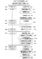
- Figure 5 is a control state in which the microcomputer is operating in the normal mode (step 300), first whether the microcomputer is battery voltage using the battery cell protection circuit 220 is a predetermined threshold value V 2 less The determination is made (step 301).
- Threshold V 2 is the threshold value for monitoring the overcharged state of the battery cell, if it exceeds the threshold value V 2 returns to step 301 to clear the timer A and timer B (step 308). If YES in step 301, the microcomputer uses the current detection circuit 227 to determine that the charging current is less than or equal to the threshold value I C (step 302).
- the threshold value I C is the upper limit value of the normal charging current range. In the case where the charging current is below the threshold value I C, the process proceeds to step 303, if it exceeds the threshold value I C returns to step 301 to clear the timer A and timer B (step 308).
- step 303 it is determined whether the discharge current is below the threshold value I 1 serving limit acceptable.
- the process proceeds to step 304 if the threshold value I 1 or less, if it exceeds the threshold value I 1 returns to step 301 to clear the timer A and timer B (step 308).
- step 304 the microcomputer determines whether the battery temperature is equal to or less than the threshold value T 1 which is an allowable upper limit value. In the case of the threshold value T 1 or less, that is, in the normal state, the process proceeds to step 305 and exceeds the threshold value T 1 Since the case is an abnormal state, the timer A and the timer B are cleared (step 308), and the microcomputer 250a maintains the normal mode by proceeding to step 301. At this time, what kind of battery management control is to be performed according to the battery temperature is managed by a program (not shown) different from FIG.
- step 305 the microcomputer measures the voltage of the LD terminal 168 from the output of the terminal voltage detection circuit 228, and determines whether the LD terminal voltage is in the low state (step 305). If the LD terminal voltage is low, this means that the connected external device (electrical device main unit or charging device) includes a microcomputer. In this case, shutdown transition processing using timer A is performed. Run. First, it increments the count of the timer A, determines whether the count value of the timer A is equal to or greater than the threshold value N A (step 307). In step 307, if it is less than the threshold value N A returns to step 301, if less than the threshold value N A, performs shutdown processing of the microcomputer 250a of the control unit 250 (step 309). In this manner, when a state of not being the use of a certain time only the battery pack 100 to the timer A reaches the threshold N A is followed, it is automatically shut down microcomputer 250a of the battery pack 100 side it can.
- step 305 when the LD terminal voltage is high, it means that the external device (electrical device main body or charging device) connected does not include the microcomputer, and in this case, the microcomputer of the external device side In conjunction with this, the microcomputer of the battery pack 100 can not be shut down, and the microcomputer of the battery pack 100 can not be activated in conjunction with the activation of the microcomputer of the external device. Therefore, the transition control to the power saving mode of the microcomputer 250a is spontaneously performed on the battery pack 100 side without interlocking with the power tool main body 1A side. That is, at step 310, the timer B is used to execute sleep mode transition processing. First, the timer B count is incremented (step 310).
- Step 311 it is determined the count value of the timer B is a predetermined time value for shifting to the sleep mode, whether words or equal to or greater than the threshold value N B (Step 311). If the count value is less than the threshold value N B returns to step 301, if the count value is not less than the threshold value N B, performs the migration processing of the timer B of the control unit 250 after clearing to zero the microcomputer sleep mode (step 312, 313).
- the subsequent procedures for entering the sleep mode of the microcomputer are known, and thus the individual descriptions are omitted.
- the counterpart device does not include a microcomputer in the body, once only followed nonuse state of the battery pack 100 a certain time until the timer A reaches the threshold N B, the battery pack 100 side
- the microcomputer is automatically put into sleep mode. By this transition, power consumption by the microcomputer in the battery pack 100 can be suppressed.
- FIG. 6 is a flowchart showing control of a state in which the microcomputer is operating in the sleep mode (step 350).
- the microcomputer on the battery pack 100 side determines, using the battery cell protection circuit 220, whether the battery voltage is equal to or higher than the threshold value V 1 (step 351).
- Threshold V 1 was, in the same manner as described in FIG. 5, a threshold value for monitoring the over-discharge state of the battery cell, a normal to higher than the threshold value V 1 is, in the case of less than the threshold value V 1 external charging It is an overdischarged condition that must be charged using the device.
- step 362 to shift to the normal mode, to judge again in the normal mode battery protection routine whether or not it is the overdischarged state, and send the discharge inhibition signal 241. Since the LD terminal 168 falls to the ground potential when the discharge inhibition signal 241 is sent, the power supply shutdown condition when the flow returns to the flowchart of FIG. The microcomputer 250a shuts down after the passage of N A. If it is determined in step 351 that the voltage is higher than the threshold V 1 , the process proceeds to step 352.
- step 352 the microcomputer 250a determines whether the battery voltage is the threshold value V 2 below using the battery cell protection circuit 220.
- Threshold V 2 is a threshold voltage indicative of the abnormally high voltage, if a certain threshold value V 2 or more because an abnormal value improbable normal or overcharged state, rather than intermittent control as sleep mode, continuous It proceeds to step 362 to shift to the normal mode so as to enable general control (step 352).
- the battery protection routine performs an unillustrated abnormality countermeasure process according to the overvoltage. Because if it is less than the threshold value V 2 it is normal proceeds to step 353.
- the microcomputer uses the current detection circuit 227 to determine whether the charging current is less than or equal to the threshold value I C (step 353).
- the charging current exceeds the threshold value I C , this is an abnormal value, and therefore, instead of the intermittent control such as in the sleep mode, the process proceeds to step 362 so as to enable continuous control. Migrate. If it is determined in step 353 that the charging current is less than or equal to the threshold value I C , then the process proceeds to step 354.
- the microcomputer determines that the discharge current is equal to or less than the threshold value I 1 using the current detection circuit 227 (step 353).
- step 362 If the discharge current is larger than the threshold I 1, there is a high possibility of overheating or battery cell deterioration, so the process proceeds to step 362 to shift to the normal mode to execute the specified overcurrent protection process (not shown). It can be so. If the discharge current is less than or equal to the threshold I 1 , the process proceeds to step 355.
- step 355 the microcomputer, with a cell temperature detection means 231 (see FIG. 3) to determine the temperature of the battery cell is thresholds T 1 below, the step 356 because if the thresholds T 1 below normal move on. During abnormal state where the temperature of the battery cell exceeds the thresholds T 1 shifts to the normal mode proceeds to step 362.
- step 356 the microcomputer 250a measures the voltage of the LD terminal 168 using the terminal voltage detection circuit 228 (see FIG. 3) to determine whether the battery pack 100 has been removed from the counterpart device (electric tool main body or charging device) Determine if. When connected to the electric power tool main body 1A having no microcomputer, the voltage of the LD terminal 168 is high, and when the battery pack 100 is removed, the voltage of the LD terminal 28 becomes low.
- step 356 when the battery pack 100 is removed, the process proceeds to step 362, and the microcomputer 250a on the battery pack 100 side shifts to the normal mode.
- the battery pack 100 When the battery pack 100 is not removed, the voltage of the LD terminal 28 remains high, but the external device being connected does not include the microcomputer. Since it can not be interlocked with the microcomputer on the side, the sleep setting is performed independently on the microcomputer 250a side (step 357).
- the sleep setting is control for reducing power consumption by shutting off the power supply to most of the circuits of the microcomputer 250a.
- the sleep mode is changed to the active state (step 361), and the process shifts to step 362 to shift to the normal mode.
- step 358 it is determined whether or not a predetermined time for the microcomputer to return to the active state from the sleep state has elapsed (step 359), and if it has elapsed, the microcomputer is returned to the active state. (Step 360) Return to Step 351. If it is determined in step 359 that the predetermined time has not elapsed, the process returns to step 358.
- the microcomputer 250a included in the control unit 250 of the battery pack 100 sets the sleep mode of the microcomputer 250a depending on whether the external device side being connected includes the microcomputer 60a or in the sleep mode. It is possible to switch between shutdown and control of the normal mode without using it.
- the microcomputer 250a in the sleep mode will not shut down. Therefore, by counting the continuous operation time T S of the sleep mode of the microcomputer 250a, the predetermined threshold continuous operation time T S, the microcomputer 250a may be controlled so as to shut down if, for example was a 1 week.
- the shutdown does not occur only in FIG. 6, the shutdown occurs in the combination of FIG. 6 and FIG.
- Operation becomes either voltage V 2 or less when continues the sleep mode in Fig. Then it shifts to the normal mode.
- the microcomputer 250a When the mode is shifted to the normal mode in FIG. 7 and the voltage is further lowered to be in the overdischarge state, the microcomputer 250a outputs the discharge inhibition signal 241, and the LD terminal 168 becomes low.
- the timer A reaches a predetermined value or more, the microcomputer 250a shuts down.
- FIG. 7 is a view for explaining the control procedure of the operation example 1 of the battery pack 100 according to this embodiment, and is a flowchart showing the operation example 1 for the power tool main body 1 in which the control unit 60 of the main body is also included .
- This flowchart is started by the worker attaching the battery pack 100 to the battery pack mounting portion 10 of the power tool main body 1.
- the power from the battery pack 100 is supplied to the power tool main body 1, so the power management circuit 62 of the battery pack 100 is powered. Is supplied and turned on (step 402), and the power management circuit 62 turns on the power supply circuit 61.
- the reference voltage VDD2 is switched from 0 V to 5 V (step 403).
- steps 404 to 410 on the left side of the middle step are control flows of the microcomputer 60a on the power tool main body 1 side
- steps 411 to 416 on the right side of the middle step are control flows of the microcomputer 250a on the battery pack 100 side.
- steps 404-410 and steps 411-416 are processed in parallel.
- step 403 when the reference voltage VDD2 is switched from 0 V to 5 V, the microcomputer 60a included in the control unit 60 of the power tool main body 1 is activated (step 405).
- the microcomputer 60a controls the motor 5 on the side of the power tool main body 1 (step 406), but the contents of the motor control are the same as in the conventional control, so the detailed description thereof will be omitted.
- the control unit 250 of the battery pack 100 is activated (step 414).
- the microcomputer 250a sends the power supply self-holding signal 224 to the power management circuit 222 (step 415).
- the power management circuit 222 maintains the on state in which the power supply circuit 221 continues the output.
- the microcomputer 250a on the battery pack side performs battery protection control (step 416). Since the battery protection control is the same as a known control method, the detailed description here is omitted.
- step 407 When the worker turns off the trigger switch 4 during the control of step 406 (step 407), the motor 5 is stopped. Then, the microcomputer 60a on the main body side keeps sending the self-holding signal 62a to the power management circuit 62 for a predetermined time after the trigger switch 4 is turned off, so that the power management circuit 62 turns the power circuit 61 on. maintain.
- step 408 the microcomputer of the control unit 60 turns off (turns low) the self hold signal 62a sent to the power management circuit 62, whereby the power management circuit 62 operates the power circuit.
- the output of the reference voltage VDD2 from 61 is stopped.
- the control unit 60 including the microcomputer 60a shuts down by losing the power (Step 417).
- the microcomputer 60a on the main body side shuts down, the voltage of the LD terminal 28 drops from about 5 V to about 0 V (step 418). Then, the microcomputer 250a on the battery pack side detects that the voltage of the LD terminal 168 has been switched by the change in the output of the terminal voltage detection circuit 228. The microcomputer 250a keeps sending the self-holding signal 224 for a predetermined time, and the power management circuit 222 keeps the power circuit 221 in the ON state.
- the microcomputer of the control unit 250 stops (turns low) the self-holding signal 224 sent to the power management circuit 222 (step 420). Then, the power supply circuit 221 is turned off, the reference voltage VDD1 changes from 3.3V to 0V (step 421), and the control unit 250 including the microcomputer 250a shuts down by losing the power (step 422).
- FIG. 8 is a view for explaining the control procedure of the operation example 2 of the battery pack 100 according to this embodiment, and is a flowchart showing an operation example 2 for the power tool main body 1 in which the control unit 60 of the main body is also included .
- This flowchart is started by the worker attaching the battery pack 100 to the battery pack mounting portion 10 of the power tool main body 1, and the procedure of steps 400 to 406 and 411 to 416 is the operation example shown in FIG. And so repeated description is omitted.
- the control unit 60 performs the motor control of step 406 on the side of the power tool main body 1, and when the operator operates the trigger switch 4, activation and stop of the motor 5 are repeated a plurality of times.
- step 430 the worker removes the battery pack 100 from the power tool main body 1 (step 430). Then, the DC power from the battery pack 100 to the power supply circuit 61 on the side of the electric power tool main body 1 disappears, so the power supply circuit 61 is turned off and the reference voltage VDD2 becomes 0V (step 431). Further, the microcomputer 60a of the control unit 60 is also shut down by losing the power (step 432). On the other hand, on the battery pack 100 side, since the voltage of the LD terminal 168 is almost 0 V, the microcomputer 250a of the control unit 250 detects that state (step 418), and keeps the microcomputer 250a in normal mode until a predetermined time elapses. Wait as it is (step 419).
- the microcomputer 250a of the control unit 250 stops (turns low) the self-holding signal 224 sent to the power management circuit 222 (step 420). Then, the power supply circuit 221 is turned off, the reference voltage VDD1 changes from 3.3 V to 0 V (step 421), and the microcomputer of the control unit 250 also shuts down by losing the power (step 422). Stop.
- the terminal voltage of the LD terminal 168 becomes low.
- the microcomputer 250a can shift to the power saving mode (sleep mode, shutdown) when the time when the terminal voltage of the LD terminal 168 is low continues for a predetermined time or more.
- FIG. 9 is a diagram for explaining the control procedure of the operation example 3 of the battery pack 100 of the present embodiment.
- FIG. 9 shows control in the case of the power tool main body 1A having no control unit including a microcomputer as a counterpart device to which the battery pack 100 is connected (step 500).
- This flow chart is started by the worker attaching the battery pack 100 to the battery pack mounting portion 10 of the power tool main body 1 (step 501).
- the control procedure is shown, and the operation shown on the left is the operation of the power tool main body 1A.
- the power tool main body 1A When the battery pack 100 is attached to the power tool main body 1A, the power tool main body 1A is in a usable state, and the operator turns on the trigger switch 4 (step 502) to supply power to the motor 5.
- the motor 5 is activated by turning on and the motor 5 is turned on (step 503).
- the trigger switch 4 is turned off (step 504), the power supplied to the motor 5 is cut off, so the motor 5 is stopped and the motor 5 is turned off. (Step 505).
- the operations of steps 502 to 505 are repeated not only once but a plurality of times depending on the work target.
- the control on the battery pack 100 side corresponding to steps 502 to 505 is such that when the battery pack 100 is attached in step 501, the voltage VCC of the battery pack 100 is substantially applied to the LD terminal 168 as shown in FIG. Step 510). Then, since a predetermined voltage is applied to the power management circuit 222 as the power supply start signal 223, the power management circuit 222 is turned on (step 511). When the power management circuit 222 is activated, the power supply circuit 221 is activated and turned on, whereby the power supply voltage VDD1 is supplied from the power supply circuit 221 to the control unit 250 (step 512).
- the control unit 250 As the power supply voltage VDD1, as a microcomputer included in the control unit 250, an MPU (Micro-processing unit) operating at an operating voltage of 3.3 V is used.
- the control unit 250 recovers from the sleep mode and enters the on state, that is, the normal mode (step 513).
- the microcomputer of the control unit 250 sends the self-holding signal 224 to the power management circuit 222 to keep the power circuit 221 on as long as there is no power shutoff instruction from the microcomputer (step 514). .
- the power supply management circuit 222 turns on the power supply circuit when either the power supply start signal 223 becomes high level or the self-holding signal 224 becomes high level, thereby turning on the power supply circuit, and the power supply start signal 223 becomes self-held.
- the microcomputer of the control unit 250 on the battery pack side performs battery protection control. Since the battery protection control is the same as a known control method, the detailed description here is omitted.
- the microcomputer of the battery pack 100 detects that the power tool main body 1A has not been used for a predetermined time or more, for example, a predetermined threshold "threshold T 1 " or more has passed (step 516), the microcomputer The mode is shifted from the normal mode to the sleep mode (step 517). In this embodiment, to set the thresholds T 1 as 2 hours, the last trigger operation of the power tool main body 1A shifts to the sleep mode after the lapse 2 hours from the completion.
- the time for shifting from the normal mode to the sleep mode when the battery pack 100 is not used is not only 2 hours, but may be set from several minutes to several hours.
- the sleep mode of the microcomputer is a mode in which the operation of the CPU and peripheral modules is stopped while the oscillation is stopped by oscillating the main clock intermittently.
- the built-in regulator of the microcomputer continues the operation, so that the built-in regulator can be used as an intermittent start trigger of the oscillation of the main clock. Since the purpose is to shift to the “power saving mode” to reduce the power consumption of the microcomputer in step 517, it is limited to only the sleep mode in which the main clock is intermittently oscillated to realize the power saving mode. Alternatively, other microcomputer power saving techniques may be used.
- the microcomputer shifts to the sleep mode in step 517, when the worker turns on the trigger switch 4 (step 506), the motor 5 is turned on by supplying electric power to the motor 5 (step 507). .
- the microcomputer on the battery pack 100 side performs current monitoring using the current detection circuit 227 when intermittently started, so the current value is equal to or more than a predetermined value, for example, to the external connection device side such as the power tool main body 1 etc. If it is detected that the threshold current I min , which is the lowest current value at which current can flow, is exceeded (step 518), the microcomputer of the control unit 250 returns from the sleep mode to the normal mode (step 519).
- the microcomputer of the control unit 250 detects whether the voltage of the battery cells 146a to 146e is less than or equal to a predetermined threshold value V 1 (step 520).
- the predetermined threshold value V 1 was a predetermined value for determining that the battery cells 146a ⁇ 146e is overdischarged state, since in the case of the threshold value V 1 or the battery voltage is normal (usable state),
- the shutdown maintaining circuit 260 is in an operable state.
- Step 521 Switching the discharge inhibition / permission signal from low to high turns on the switching element M1 (discharge inhibition state) and drops the potential of the LD terminals 28 and 168 to the ground potential (step 522).
- the gate voltage to the switching element M31 on the side of the electric power tool main body 1A decreases, and the switching element M31 is turned off (source-drain cutoff) (step 508).
- the power supply to the motor 5 is cut off, the rotation of the motor 5 is stopped (step 509).
- step 522 On the battery pack 100 side, as a result of step 522, the voltage of the LD terminal 168 becomes approximately 0 V (step 523).
- the control unit 250 stands by until a predetermined time elapses (step 524), and turns the self-holding signal 224 for keeping the power management circuit 222 on (off) to operate the power circuit 221. Are turned off (steps 525 and 526). Then, the supply of the reference voltage VDD1 (3.3 V) to the microcomputer of the control unit 250 is stopped, and the microcomputer shuts down (step 527).
- VDD1 3.3 V
- the shutdown maintaining circuit 260 maintains the operating state, and the value of the voltage VCC of the battery pack 100 is significantly lower than the total voltage corresponding to the threshold V 1 in battery cell units, and even the operation of the shutdown maintaining circuit 260 becomes impossible.
- the switching element M2 is maintained in the on state until the voltage drops to the low voltage V 0 (V 0 ⁇ V 1 ). It should be noted that if the voltage is less than the low voltage V 0 at which even the operation of the shutdown maintaining circuit 260 can not be performed, the power management circuit 222 does not operate even if a voltage of 3.3 V or more is applied to the LD terminal 168. There is no need to restart.
- the battery pack 100 changes the power saving mode (for example, the normal mode of the microcomputer) according to whether the microcomputer is included in the other device to be attached, ie, the power tool body or the charging device. We made it to shift to sleep mode).
- the power saving mode when the trigger is pulled and the power tool main body 1 is started, the microcomputer is immediately restarted even in the normal mode, so power saving of the battery pack is prevented without affecting the operation of the power tool. Can be promoted.
- the microcomputer is shut down.
- power consumption by the microcomputer of the battery pack 100 can be suppressed. This suppression of power consumption is effective particularly in the standby mode when the battery pack 100 is not used.
- Discharge inhibition signal 250: control unit, 250a: microcomputer, 260: shutdown maintenance circuit, C1: capacitor, D1: diode, M1 to M3: (semiconductor) switching circuit, R1 to R5: resistance, ZD1: zener diode, VDD1: power supply voltage (reference Voltage), VDD2 ... reference voltage, VCC ... battery voltage
Landscapes
- General Chemical & Material Sciences (AREA)
- Electrochemistry (AREA)
- Chemical Kinetics & Catalysis (AREA)
- Chemical & Material Sciences (AREA)
- Engineering & Computer Science (AREA)
- Manufacturing & Machinery (AREA)
- Computer Hardware Design (AREA)
- Biophysics (AREA)
- Life Sciences & Earth Sciences (AREA)
- Charge And Discharge Circuits For Batteries Or The Like (AREA)
- Mechanical Engineering (AREA)
- Secondary Cells (AREA)
- Power Engineering (AREA)
- Battery Mounting, Suspending (AREA)
Abstract
Selon la présente invention, l'activation/la désactivation de circuits du côté d'un corps d'outil électrique et l'activation/la désactivation d'un micro-ordinateur du côté d'un bloc-batterie sont associées l'une à l'autre. Un bloc-batterie (100) comprend : une borne LD (168) qui transmet un signal d'arrêt à un corps d'appareil électrique auquel est fixé le bloc-batterie ; des éléments de batteries (146a-146e) ; un micro-ordinateur (250a) qui surveille les états de charge des éléments de batteries ; et un circuit d'alimentation électrique (221) destiné à commander le micro-ordinateur (250a). Le bloc-batterie (100) comporte un circuit de gestion (222) d'alimentation électrique qui contrôle l'activation et l'arrêt du circuit d'alimentation électrique (221) auquel est appliquée une tension d'actionnement (VDD1). Lors de l'entrée de la tension de la borne LD (168), le circuit de gestion (222) d'alimentation électrique arrête le circuit d'alimentation électrique (221) et désactive également le micro-ordinateur (250a) du côté du bloc-batterie en association avec la désactivation d'un micro-ordinateur (60a) du côté de l'appareil. Lorsque le micro-ordinateur (60a) du côté de l'appareil a été activé, le circuit de gestion (222) d'alimentation électrique active le micro-ordinateur (250a) en actionnant le circuit d'alimentation électrique (221) afin d'appliquer la tension d'actionnement (VDD1) au micro-ordinateur (250a).
Priority Applications (1)
| Application Number | Priority Date | Filing Date | Title |
|---|---|---|---|
| JP2019535106A JP7060020B2 (ja) | 2017-08-10 | 2018-07-27 | 電池パック及び電池パックを用いた電気機器 |
Applications Claiming Priority (2)
| Application Number | Priority Date | Filing Date | Title |
|---|---|---|---|
| JP2017-155061 | 2017-08-10 | ||
| JP2017155061 | 2017-08-10 |
Publications (1)
| Publication Number | Publication Date |
|---|---|
| WO2019031274A1 true WO2019031274A1 (fr) | 2019-02-14 |
Family
ID=65271326
Family Applications (1)
| Application Number | Title | Priority Date | Filing Date |
|---|---|---|---|
| PCT/JP2018/028260 Ceased WO2019031274A1 (fr) | 2017-08-10 | 2018-07-27 | Bloc-batterie et appareil électrique utilisant le bloc-batterie |
Country Status (2)
| Country | Link |
|---|---|
| JP (1) | JP7060020B2 (fr) |
| WO (1) | WO2019031274A1 (fr) |
Cited By (9)
| Publication number | Priority date | Publication date | Assignee | Title |
|---|---|---|---|---|
| JP2020194725A (ja) * | 2019-05-29 | 2020-12-03 | 株式会社マキタ | バッテリパック |
| JP2021182845A (ja) * | 2020-05-18 | 2021-11-25 | 北斗制御株式会社 | 電動切断工具 |
| JP2022015137A (ja) * | 2020-07-08 | 2022-01-21 | 太陽誘電株式会社 | バッテリパック及び電動アシスト車 |
| US20220115892A1 (en) * | 2018-09-14 | 2022-04-14 | Makita Corporation | Electric work machine |
| KR20220149346A (ko) * | 2021-04-30 | 2022-11-08 | 넥스콘테크놀러지 주식회사 | 휴대용 배터리팩의 운영 제어장치 및 방법 |
| WO2023049487A1 (fr) | 2021-09-27 | 2023-03-30 | Milwaukee Electric Tool Corporation | Commutateur de déclenchement de source multi-tension |
| JP2024502528A (ja) * | 2020-11-10 | 2024-01-22 | バクスター・インターナショナル・インコーポレイテッド | 点滴ポンプの再充電可能バッテリの貯蔵持続時間を延長するためのシステムおよび方法 |
| JP2024009697A (ja) * | 2022-07-11 | 2024-01-23 | トヨタ自動車株式会社 | バッテリー制御装置、制御方法、及び制御プログラム |
| US12057719B2 (en) | 2018-09-14 | 2024-08-06 | Makita Corporation | Electric work machine and battery pack |
Families Citing this family (1)
| Publication number | Priority date | Publication date | Assignee | Title |
|---|---|---|---|---|
| KR102662545B1 (ko) * | 2021-12-23 | 2024-05-03 | 린나이코리아 주식회사 | 난방 반복 타이머 운전 중 설정 실내온도 유지방법 |
Citations (5)
| Publication number | Priority date | Publication date | Assignee | Title |
|---|---|---|---|---|
| JP2012039701A (ja) * | 2010-08-04 | 2012-02-23 | Sanyo Electric Co Ltd | パック電池及び過電流検出方法 |
| JP2014054703A (ja) * | 2012-09-13 | 2014-03-27 | Panasonic Corp | 電動工具 |
| JP2015196196A (ja) * | 2014-03-31 | 2015-11-09 | 日立工機株式会社 | 電動工具 |
| WO2017022169A1 (fr) * | 2015-07-31 | 2017-02-09 | パナソニックIpマネジメント株式会社 | Dispositif de commande de batterie, appareil électronique, bloc de batterie, et procédé de commande de batterie |
| WO2017043248A1 (fr) * | 2015-09-11 | 2017-03-16 | 日立工機株式会社 | Dispositif de diagnostic de batterie et bloc-batterie |
Family Cites Families (2)
| Publication number | Priority date | Publication date | Assignee | Title |
|---|---|---|---|---|
| JP2005027354A (ja) * | 2004-10-04 | 2005-01-27 | Mitsubishi Electric Corp | 電源制御装置 |
| JP4697669B2 (ja) * | 2006-09-11 | 2011-06-08 | 日立工機株式会社 | 動力工具 |
-
2018
- 2018-07-27 JP JP2019535106A patent/JP7060020B2/ja active Active
- 2018-07-27 WO PCT/JP2018/028260 patent/WO2019031274A1/fr not_active Ceased
Patent Citations (5)
| Publication number | Priority date | Publication date | Assignee | Title |
|---|---|---|---|---|
| JP2012039701A (ja) * | 2010-08-04 | 2012-02-23 | Sanyo Electric Co Ltd | パック電池及び過電流検出方法 |
| JP2014054703A (ja) * | 2012-09-13 | 2014-03-27 | Panasonic Corp | 電動工具 |
| JP2015196196A (ja) * | 2014-03-31 | 2015-11-09 | 日立工機株式会社 | 電動工具 |
| WO2017022169A1 (fr) * | 2015-07-31 | 2017-02-09 | パナソニックIpマネジメント株式会社 | Dispositif de commande de batterie, appareil électronique, bloc de batterie, et procédé de commande de batterie |
| WO2017043248A1 (fr) * | 2015-09-11 | 2017-03-16 | 日立工機株式会社 | Dispositif de diagnostic de batterie et bloc-batterie |
Cited By (18)
| Publication number | Priority date | Publication date | Assignee | Title |
|---|---|---|---|---|
| US11979049B2 (en) * | 2018-09-14 | 2024-05-07 | Makita Corporation | Electric work machine |
| US20220115892A1 (en) * | 2018-09-14 | 2022-04-14 | Makita Corporation | Electric work machine |
| US12057719B2 (en) | 2018-09-14 | 2024-08-06 | Makita Corporation | Electric work machine and battery pack |
| JP7336264B2 (ja) | 2019-05-29 | 2023-08-31 | 株式会社マキタ | バッテリパック |
| JP2020194725A (ja) * | 2019-05-29 | 2020-12-03 | 株式会社マキタ | バッテリパック |
| JP2021182845A (ja) * | 2020-05-18 | 2021-11-25 | 北斗制御株式会社 | 電動切断工具 |
| JP7506912B2 (ja) | 2020-05-18 | 2024-06-27 | 北斗制御株式会社 | 電動切断工具 |
| JP2022015137A (ja) * | 2020-07-08 | 2022-01-21 | 太陽誘電株式会社 | バッテリパック及び電動アシスト車 |
| JP7586659B2 (ja) | 2020-07-08 | 2024-11-19 | 太陽誘電株式会社 | バッテリパック及び電動アシスト車 |
| JP2024502528A (ja) * | 2020-11-10 | 2024-01-22 | バクスター・インターナショナル・インコーポレイテッド | 点滴ポンプの再充電可能バッテリの貯蔵持続時間を延長するためのシステムおよび方法 |
| KR102563592B1 (ko) * | 2021-04-30 | 2023-08-07 | 넥스콘테크놀러지 주식회사 | 휴대용 배터리팩의 운영 제어장치 및 방법 |
| KR20220149346A (ko) * | 2021-04-30 | 2022-11-08 | 넥스콘테크놀러지 주식회사 | 휴대용 배터리팩의 운영 제어장치 및 방법 |
| WO2023049487A1 (fr) | 2021-09-27 | 2023-03-30 | Milwaukee Electric Tool Corporation | Commutateur de déclenchement de source multi-tension |
| JP2024534552A (ja) * | 2021-09-27 | 2024-09-20 | ミルウォーキー エレクトリック ツール コーポレイション | マルチ電圧源トリガスイッチ |
| JP7758439B2 (ja) | 2021-09-27 | 2025-10-22 | ミルウォーキー エレクトリック ツール コーポレイション | マルチ電圧源トリガスイッチ |
| JP2024009697A (ja) * | 2022-07-11 | 2024-01-23 | トヨタ自動車株式会社 | バッテリー制御装置、制御方法、及び制御プログラム |
| JP7632410B2 (ja) | 2022-07-11 | 2025-02-19 | トヨタ自動車株式会社 | バッテリー制御装置、制御方法、及び制御プログラム |
| US12509009B2 (en) | 2022-07-11 | 2025-12-30 | Toyota Jidosha Kabushiki Kaisha | Battery control device, control method, and non-transitory storage medium |
Also Published As
| Publication number | Publication date |
|---|---|
| JP7060020B2 (ja) | 2022-04-26 |
| JPWO2019031274A1 (ja) | 2020-03-26 |
Similar Documents
| Publication | Publication Date | Title |
|---|---|---|
| JP7060020B2 (ja) | 電池パック及び電池パックを用いた電気機器 | |
| US9203249B2 (en) | Battery pack for electric power tool, control circuit, and program | |
| JP6644733B2 (ja) | バッテリパック | |
| CN105322611B (zh) | 电池组以及用于控制电池组的方法 | |
| JP4183004B2 (ja) | 電池パック | |
| CN105009401B (zh) | 电池组和电气设备 | |
| JP6530586B2 (ja) | 2次保護ic、2次保護icの制御方法、保護モジュール、及び電池パック | |
| JP6812194B2 (ja) | 電動作業機 | |
| KR20080060177A (ko) | 배터리 상태 감시 회로 및 배터리 장치 | |
| CN101807801A (zh) | 充电控制器 | |
| US20190280341A1 (en) | Circuits, systems, and methods for protecting batteries | |
| JP6373662B2 (ja) | バッテリパック | |
| JP2005131770A (ja) | 電池パック、電動工具及び電動工具システム | |
| WO2014038165A1 (fr) | Outil de puissance | |
| JP4103828B2 (ja) | 充電式電気機器 | |
| WO2024093303A1 (fr) | Outil électrique et système de décharge | |
| KR102637309B1 (ko) | 외부에서 모드 전환이 가능한 배터리 팩 및 외부에서 배터리 팩의 모드 전환 방법 | |
| JP6462975B2 (ja) | 電源装置 | |
| US20070139847A1 (en) | Power tool with circuit protection capability | |
| US12517569B2 (en) | External and internal power management for embedded electronic devices | |
| JP7056755B2 (ja) | 電池パック及びそれを用いた電気機器 | |
| JP2019051043A (ja) | 電気掃除機 | |
| JP5033035B2 (ja) | 電池パック | |
| WO2011040347A1 (fr) | Outil à moteur, et bloc-batterie utilisé par celui-ci |
Legal Events
| Date | Code | Title | Description |
|---|---|---|---|
| 121 | Ep: the epo has been informed by wipo that ep was designated in this application |
Ref document number: 18843455 Country of ref document: EP Kind code of ref document: A1 |
|
| ENP | Entry into the national phase |
Ref document number: 2019535106 Country of ref document: JP Kind code of ref document: A |
|
| NENP | Non-entry into the national phase |
Ref country code: DE |
|
| 122 | Ep: pct application non-entry in european phase |
Ref document number: 18843455 Country of ref document: EP Kind code of ref document: A1 |