WO2019031353A1 - スピーカおよび音響装置 - Google Patents
スピーカおよび音響装置 Download PDFInfo
- Publication number
- WO2019031353A1 WO2019031353A1 PCT/JP2018/028864 JP2018028864W WO2019031353A1 WO 2019031353 A1 WO2019031353 A1 WO 2019031353A1 JP 2018028864 W JP2018028864 W JP 2018028864W WO 2019031353 A1 WO2019031353 A1 WO 2019031353A1
- Authority
- WO
- WIPO (PCT)
- Prior art keywords
- magnet
- plate
- adhesive
- yoke
- magnetic fluid
- Prior art date
- Legal status (The legal status is an assumption and is not a legal conclusion. Google has not performed a legal analysis and makes no representation as to the accuracy of the status listed.)
- Ceased
Links
Images










Classifications
-
- H—ELECTRICITY
- H04—ELECTRIC COMMUNICATION TECHNIQUE
- H04R—LOUDSPEAKERS, MICROPHONES, GRAMOPHONE PICK-UPS OR LIKE ACOUSTIC ELECTROMECHANICAL TRANSDUCERS; ELECTRIC HEARING AIDS; PUBLIC ADDRESS SYSTEMS
- H04R1/00—Details of transducers, loudspeakers or microphones
- H04R1/02—Casings; Cabinets ; Supports therefor; Mountings therein
-
- H—ELECTRICITY
- H04—ELECTRIC COMMUNICATION TECHNIQUE
- H04R—LOUDSPEAKERS, MICROPHONES, GRAMOPHONE PICK-UPS OR LIKE ACOUSTIC ELECTROMECHANICAL TRANSDUCERS; ELECTRIC HEARING AIDS; PUBLIC ADDRESS SYSTEMS
- H04R1/00—Details of transducers, loudspeakers or microphones
- H04R1/10—Earpieces; Attachments therefor ; Earphones; Monophonic headphones
-
- H—ELECTRICITY
- H04—ELECTRIC COMMUNICATION TECHNIQUE
- H04R—LOUDSPEAKERS, MICROPHONES, GRAMOPHONE PICK-UPS OR LIKE ACOUSTIC ELECTROMECHANICAL TRANSDUCERS; ELECTRIC HEARING AIDS; PUBLIC ADDRESS SYSTEMS
- H04R25/00—Electric hearing aids
-
- H—ELECTRICITY
- H04—ELECTRIC COMMUNICATION TECHNIQUE
- H04R—LOUDSPEAKERS, MICROPHONES, GRAMOPHONE PICK-UPS OR LIKE ACOUSTIC ELECTROMECHANICAL TRANSDUCERS; ELECTRIC HEARING AIDS; PUBLIC ADDRESS SYSTEMS
- H04R9/00—Transducers of moving-coil, moving-strip, or moving-wire type
- H04R9/02—Details
-
- H—ELECTRICITY
- H04—ELECTRIC COMMUNICATION TECHNIQUE
- H04R—LOUDSPEAKERS, MICROPHONES, GRAMOPHONE PICK-UPS OR LIKE ACOUSTIC ELECTROMECHANICAL TRANSDUCERS; ELECTRIC HEARING AIDS; PUBLIC ADDRESS SYSTEMS
- H04R9/00—Transducers of moving-coil, moving-strip, or moving-wire type
- H04R9/02—Details
- H04R9/04—Construction, mounting, or centering of coil
Definitions
- the present disclosure relates to a speaker provided with a magnetic fluid, and an acoustic device provided with the speaker.
- Patent Document 1 discloses a speaker using a magnetic fluid.
- the magnetic fluid is disposed between the voice coil disposed in the magnetic gap of the magnetic circuit and the plate constituting the magnetic circuit.
- the vibration of the voice coil is stabilized by arranging the magnetic fluid between the voice coil and the plate.
- the above-described conventional speaker has not been able to effectively improve the distortion characteristics.
- the present disclosure provides a speaker that can effectively improve distortion characteristics.
- a speaker includes a yoke, a magnet fixed to the yoke, a plate fixed to a surface opposite to the surface fixed to the yoke of the magnet, the yoke, and the yoke
- a voice coil provided in each of the plates and disposed in a magnetic gap formed between opposing parts disposed facing each other, a diaphragm fixed to the voice coil, the yoke, and the yoke
- a coating film containing a fluorine resin is formed on the surface of the portion.
- An earphone according to an aspect of the present disclosure includes the above speaker.
- the loudspeaker according to the present disclosure can effectively improve distortion characteristics.
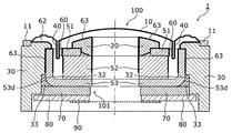
- FIG. 1 is a perspective view showing the appearance of the loudspeaker according to the embodiment.
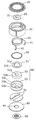
- FIG. 2 is an exploded perspective view of the speaker.
- FIG. 3 is a cross-sectional view of the speaker of FIG. 1 taken along III-III.
- FIG. 4 is a cross-sectional view of the speaker of FIG. 1 taken along IV-IV.
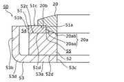
- FIG. 5 is an enlarged view of a joint portion of a stopper, a plate and a magnet in the speaker of FIG. 3 in a state where an adhesive portion is not formed.
- FIG. 6 is an enlarged view of a joint portion of a stopper, a plate and a magnet in the speaker of FIG. 3 in a state where an adhesive portion is formed.
- FIG. 1 is a perspective view showing the appearance of the loudspeaker according to the embodiment.
- FIG. 2 is an exploded perspective view of the speaker.
- FIG. 3 is a cross-sectional view of the speaker of FIG. 1 taken along III-III.
- FIG. 4 is
- FIG. 7 is a view for explaining a fluorine coating treatment method for an assembly in a state where the diaphragm and the support member are fixed to each other.
- FIG. 8 is a view for explaining a fluorine coating treatment method for an assembly in which the magnetic circuit and the stopper are fixed to each other.
- FIG. 9 is a view for explaining a method of adhesively bonding an assembly which has been subjected to a fluorine coating treatment.
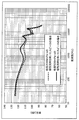
- FIG. 10 is a graph showing a relationship between temperature change and viscosity change of magnetic fluid having different viscosities at a reference temperature.
- FIG. 11 is a graph showing frequency characteristics of output sound pressure of speakers using magnetic fluids different in viscosity at a reference temperature.
- FIG. 12 is a perspective view showing the appearance of the loudspeaker of the second embodiment.
- FIG. 13 is an exploded perspective view of the loudspeaker according to the second embodiment.
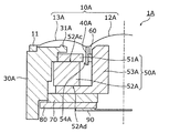
- FIG. 14 is a cross-sectional view of the speaker of FIG. 12 taken along line XIV-XIV.
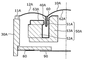
- FIG. 15 is an XV-XV cross-sectional view of the speaker of FIG.
- FIG. 16 is a cross-sectional view taken along line XIV-XIV of the speaker of FIG.
- FIG. 17 is an XV-XV cross-sectional view of the speaker of FIG. 12 after the fluorine coating process.
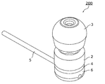
- FIG. 18 is an external view showing an earphone using the speaker according to the embodiment.
- FIG. 19 is an exploded perspective view of the earphone.
- the magnetic circuit of the speaker of Patent Document 1 is configured by fixing the yoke, the magnet, and the plate to each other with an adhesive or the like in a stacked state.
- the magnet is configured by being cut at both sides in the thickness direction, and a minute warpage occurs in the cut surface.
- the plate is formed by press molding, minute warpage due to the press occurs. As described above, micro-warpage is generated on the adhesive surfaces of the components constituting the magnetic circuit, and therefore, when these components are superposed using an adhesive, a state including air between them and become. Therefore, the yoke, the magnet, and the plate are adhesively fixed in a state where a minute gap is generated between them.
- the magnetic circuit has a gap, and the magnetic fluid is disposed between the plate forming the magnetic circuit and the voice coil. Therefore, the magnetic fluid is likely to be drawn into the gap of the magnetic circuit by capillary action.
- the voice coil in which the magnetic fluid is disposed generates Joule heat when a voltage is applied. For this reason, the magnetic fluid is easily affected by Joule heat from the voice coil and easily changes in temperature, so the viscosity is likely to change significantly. And when the viscosity of magnetic fluid changes a lot, there also exists a subject that the above-mentioned capillary phenomenon tends to occur.
- a speaker includes a yoke, a magnet fixed to the yoke, a plate fixed to a surface opposite to the surface fixed to the yoke of the magnet, and the yoke
- a voice coil disposed in each of the magnetic plates and the plate and disposed in a magnetic gap formed between facing portions disposed facing each other, a diaphragm fixed to the voice coil, and the yoke
- a coating film containing a fluorocarbon resin is formed on the surface of the contact portion.
- the surface energy between at least one of the plate and the voice coil and the magnetic fluid can be reduced, and the diaphragm can be vibrated more smoothly. Therefore, the distortion characteristic of the speaker can be improved.
- the coating film may be formed on the surface of a recess formed by the yoke, the magnet, and the plate.
- the surface energy of the surface of the yoke, the magnet and the plate can be reduced, and the magnetic fluid can be prevented from being drawn between the yoke, the magnet and the plate by capillary action.
- the coating film may be formed on the surface of the voice coil and at least a junction of the voice coil and the diaphragm on the surface of the diaphragm on which the voice coil is disposed.
- the surface of the yoke of the part by which the said yoke is supported by the said supporting member may have an area
- the yoke and the support member can be effectively adhered and fixed.
- the coating film may further include a fluorescent member that emits light when receiving ultraviolet light.
- the semiconductor device further includes a first adhesive portion bonding and bonding the plate and the magnet, wherein the first adhesive portion is hardened in the gap between the bonding surface of the plate and the magnet.
- a first portion and a second portion of the first adhesive cured outside of the gap, the second portion being formed over the outlet of the gap in a direction different from that toward the magnetic fluid May be
- the second portion of the first adhesive portion covers the outlet of the gap between the plate and the joint surface of the magnet. Therefore, even if the magnetic fluid intrudes into the gap, the second portion suppresses the leakage of the magnetic fluid from the outlet of the gap. Thus, the decrease in magnetic fluid can be suppressed.
- the yoke may be located at a corner formed by the surface of the plate and the surface of the magnet, and the corner may be adjacent to the outlet of the gap.
- the second part of the first adhesive part blocks the outlet of the gap adjacent to the plate and the corner of the magnet.
- the second part located at the corner can effectively close and seal the outlet of the gap.
- the apparatus further includes a bonding member bonded to the plate and the magnet, and a second adhesive portion bonding and bonding the plate and the magnet to the bonding member, wherein the bonding member is an outlet of the gap. And may be disposed over the second portion.
- the joining member covers the outlet of the gap and the second portion of the first adhesive portion and is adhesively bonded to the plate and the magnet, so that the magnetic fluid leaks through the outlet and the second portion of the gap. It can be suppressed.
- the second adhesive portion may cover the whole of the yoke.
- the second adhesive portion can suppress the leakage of the magnetic fluid through the second portion of the first adhesive portion.
- the bonding member may form a space for housing the yoke together with the plate and the magnet.
- the second portion of the first adhesive portion can be formed in a lump in accordance with the shape of the space.
- the second part can cover and seal the entire outlet of the gap with a sufficient thickness.
- the plate has a corner at an end distal to the outlet of the gap on the surface adjacent to the outlet of the gap, and the joining member has a shape to be fitted to the corner of the plate
- the second adhesive portion may extend across the corner of the plate.
- the second adhesive portion extends across the corner of the plate. For this reason, even when the magnetic fluid intrudes into the gap between the plate and the bonding member, it becomes difficult for the infiltration to proceed at the corner. Thus, the progress of the infiltration of the magnetic fluid can be suppressed.
- the 2nd adhesive agent which comprises a said 2nd adhesive agent part is a visible light curable adhesive agent, and the said joining member may have translucency.
- the second adhesive constituting the second adhesive portion may contain a fluorescent agent that emits light when receiving ultraviolet light.
- the viscosity at a reference temperature (for example, 27 ° C.) is, for example, 4000 mPa ⁇ s in order to prevent the magnetic fluid from being scattered by wind pressure by the diaphragm.
- a reference temperature for example, 27 ° C.
- Used a large magnetic fluid the larger the viscosity of the solvent (oil) used for the magnetic fluid, the larger the range of change in viscosity due to temperature change. That is, the magnetic fluid used for the conventional speaker has the characteristic that the viscosity also changes significantly as the temperature changes.
- the output sound pressure changes in accordance with the magnitude of the viscosity of the magnetic fluid. That is, since the magnitude of the viscosity of the magnetic fluid changes when the temperature changes, there is a problem that the output sound pressure of the speaker changes.
- the voice coil in which the magnetic fluid is disposed generates Joule heat when a voltage is applied. For this reason, the magnetic fluid is easily affected by Joule heat from the voice coil and easily changes in temperature, so the viscosity is likely to change significantly.
- the magnetic fluid having a large viscosity has a large drop width in which the viscosity decreases due to the temperature rise. Be more susceptible.
- the influence of the capillary phenomenon is larger as the decrease width of the viscosity is larger. Therefore, in consideration of the influence of the capillary phenomenon, it is preferable that the viscosity of the magnetic fluid is small. That is, the present inventors came to use a magnetic fluid with a low viscosity to suppress the dissipation of the magnetic fluid.
- the speaker according to an aspect of the present disclosure includes a yoke, a magnet fixed to the yoke, a plate fixed to a surface opposite to the surface fixed to the yoke of the magnet, and the yoke
- a voice coil disposed in each of the magnetic plates and the plate and disposed in a magnetic gap formed between facing portions disposed facing each other, a diaphragm fixed to the voice coil, and the yoke
- a support member for supporting the diaphragm, and a magnetic fluid disposed between the facing portion of the plate and the voice coil, and the viscosity of the magnetic fluid at a predetermined reference temperature is 9 mPa ⁇ s or more.
- the minimum value of the viscosity of the magnetic fluid in the temperature range which is largely 500 mPa ⁇ s or less and exceeds the reference temperature is 9 mPa ⁇ s or more,
- the viscosity of kicking the magnetic fluid is greater than the viscosity of the magnetic fluid in said temperature range.
- the viscosity at the predetermined reference temperature is greater than 9 mPa ⁇ s and 500 mPa ⁇ s or less, the decrease in viscosity can be suppressed even when the temperature rises. Therefore, it is possible to realize a speaker capable of stably maintaining the output sound pressure.
- the magnetic saturation density of the magnetic fluid may be 22 mT or more.
- the attractive force can be maximized by the magnetic force, so that it can be effectively retained in the magnetic gap of the magnetic circuit.
- the influence of capillary action on the magnetic fluid can be reduced.
- the speaker disclosed in Patent Document 1 includes a magnet, a yoke and a plate connected to the magnet, and a voice coil disposed in a magnetic gap between the yoke and the plate.
- the voice coil is joined to the diaphragm.
- the loudspeaker comprises a magnetic fluid between the plate and the voice coil. The magnetic fluid supports the voice coil against the plate.
- the magnetic fluid may enter into a gap between members such as the plate and the magnet by capillary action and leak out from the gap.
- the amount of magnetic fluid that supports the voice coil is reduced, so that the function of the magnetic fluid to support the voice coil may be reduced, which may cause an abnormality in the speaker.
- the magnetic fluid is disposed at the edge of the plate. Furthermore, the edge of this plate is located near the joint surface of the plate and the magnet. Vibration of the voice coil at the time of generation of the sound wave also vibrates the magnetic fluid, whereby the magnetic fluid is in contact with the bonding surface. At this time, capillary action may occur in the magnetic fluid due to the surface tension of the magnetic fluid, and the magnetic fluid may intrude into the gap of the bonding surface. The infiltrated magnetic fluid leaks, for example, from the outlet of the gap located opposite to the magnetic fluid. This reduces the magnetic fluid in the magnetic gap and reduces the function of the magnetic fluid. Therefore, the present inventors have proposed the following techniques in order to suppress the decrease of the magnetic fluid as described above.
- a speaker includes a magnet, a first facing portion, a first member magnetically coupled to a first magnetic pole of the magnet, and a first member facing the first facing portion and the first member.
- a second member magnetically coupled to a second magnetic pole opposite to the first magnetic pole of the magnet and having a second facing portion disposed outward of the one facing portion, and the first facing portion A voice coil disposed in a magnetic gap formed between the second facing portions, a magnetic fluid disposed at least between the voice coil and the first facing portion, the first member, and the magnet
- a first adhesive portion bonding and bonding the first adhesive portion, the first adhesive portion being a first portion in which the first adhesive is cured in the gap between the bonding surface of the first member and the magnet, and the gap And the second portion of the first adhesive cured, Serial second portion is formed to cover the outlet of the gap orientation different from the direction toward the magnetic fluid.
- the second portion of the first adhesive portion covers the outlet of the gap between the joining surface of the first member and the magnet. Therefore, even if the magnetic fluid intrudes into the gap, the second portion suppresses the leakage of the magnetic fluid from the outlet of the gap. Thus, the decrease in magnetic fluid can be suppressed.
- the second portion is located at a corner formed by the surface of the first member and the surface of the magnet, and the corner is adjacent to the outlet of the gap. Good.
- the second portion of the first adhesive portion closes the outlet of the gap adjacent to the corner of the first member and the magnet. The second part located at the corner can effectively close and seal the outlet of the gap.
- the speaker according to an aspect of the present disclosure includes a third member joined to the first member and the magnet, and a second adhesive portion bonding and joining the first member, the magnet, and the third member.
- the third member may be disposed over the outlet of the gap and the second portion. According to the above aspect, the third member covers the outlet of the gap and the second portion of the first adhesive portion and is adhesively bonded to the first member and the magnet, so that the magnetic fluid through the outlet and the second portion of the gap Leakage can be suppressed.
- the second adhesive portion may cover the entire second portion. According to the above aspect, the second adhesive portion can suppress the leakage of the magnetic fluid through the second portion of the first adhesive portion.
- the third member may form a space for housing the second portion together with the first member and the magnet.
- the second portion of the first adhesive portion can be formed into a mass in accordance with the shape of the space.
- the second part can cover and seal the entire outlet of the gap with a sufficient thickness.
- the first member has a corner at an end distal to the outlet of the gap on the surface adjacent to the outlet of the gap
- the third member is the first member
- the second adhesive portion may extend across the corner of the first member. According to the above aspect, the second adhesive portion extends across the corner of the first member. For this reason, even when the magnetic fluid intrudes into the gap between the first member and the third member, it becomes difficult for the infiltration to proceed at the corner. Thus, the progress of the infiltration of the magnetic fluid can be suppressed.
- the second adhesive constituting the second adhesive portion may be a visible light curable adhesive, and the third member may have translucency. According to the above aspect, reliable and quick curing of the second adhesive is possible.
- the second adhesive constituting the second adhesive portion may include a fluorescent agent. According to the above aspect, it is possible to confirm the adhesion state of the second adhesive by projecting light that causes the fluorescent agent to emit light to the second adhesive after bonding of the members. Thus, it is possible to form a good second adhesive portion.
- an earphone according to one aspect of the present disclosure includes the above speaker. According to the above aspect, the same effect as the speaker according to one aspect of the present disclosure can be obtained.
- a hearing aid according to one aspect of the present disclosure includes the above speaker. According to the above aspect, the same effect as the speaker according to one aspect of the present disclosure can be obtained.
- a portable terminal device includes the above-described speaker. According to the above aspect, the same effect as the speaker according to one aspect of the present disclosure can be obtained.
- the sound apparatus which concerns on 1 aspect of this indication is equipped with the said speaker and the housing which accommodates the said speaker.
- Embodiment 1 The loudspeaker according to the first embodiment will be described with reference to FIGS. 1 to 11.
- the speaker according to the first embodiment is a speaker having an internal magnet type magnetic circuit.
- FIG. 1 is a perspective view showing the appearance of the loudspeaker according to the first embodiment.
- FIG. 2 is an exploded perspective view of the loudspeaker according to the first embodiment.
- FIG. 3 is a cross-sectional view of the speaker of FIG. 1 taken along III-III.
- FIG. 4 is a cross-sectional view of the speaker of FIG. 1 taken along IV-IV.
- the speaker 1 includes the diaphragm 10, the support member 30, the voice coil 40, the plate 51, the magnet 52, the yoke 53, and the magnetic fluid 60, as shown in FIGS. That is, an internal magnet type magnetic circuit is formed by the plate 51, the magnet 52, the yoke 53 and the magnetic fluid 60.
- the speaker 1 may further include a stopper 20, a spacer 70, a substrate 80, and a dustproof net 90.
- the direction in which the sound is emitted from the speaker 1 is referred to as the front, and the opposite direction is referred to as the back.
- the diaphragm 10 has a thin disk shape.
- the diaphragm 10 has a shape in which the vicinity of the center when viewed from the front bulges to the front side relative to the outer peripheral edge.
- the diaphragm 10 also includes a central disk-shaped diaphragm body 12 and an annular or ring-shaped diaphragm edge 13 surrounding the outer periphery of the diaphragm body 12.
- the diaphragm edge 13 is flexible, and the diaphragm body 12 is more rigid than the diaphragm edge 13.
- the radial width of the diaphragm edge 13 is smaller than the radial width of the diaphragm body 12A.
- the outer peripheral edge of the diaphragm body 12 and the inner peripheral edge of the diaphragm edge 13 are connected to each other, and the diaphragm body 12 and the diaphragm edge 13 are integrated.
- the diaphragm 10 is provided with an outer peripheral ring 11 on the outer peripheral edge of the diaphragm edge 13 and is supported by the support member 30 by fixing the outer peripheral ring 11 to the support member 30.
- the diaphragm body 12 is coupled to the voice coil 40 near its outer peripheral edge. Thus, when the voice coil 40 vibrates, the diaphragm edge 13 is deformed and the diaphragm body 12 and the diaphragm edge 13 vibrate together.
- a coating film containing a fluorine resin may be formed on the rear surface of the diaphragm 10. The details of the fluorine coating treatment for forming the coating film will be described later.
- the support member 30 is a cylindrical member, and supports the diaphragm 10 at its front end.
- the support member 30 accommodates the stopper 20, the voice coil 40, the plate 51, the magnet 52, the yoke 53 and the magnetic fluid 60 inside.
- the support member 30 may further accommodate the substrate 80 and the dustproof net 90.
- the substrate 80 and the dustproof net 90 may be disposed at the end of the support member 30 opposite to the diaphragm 10 in the front-rear direction.
- the support member 30 is made of, for example, metal, resin or the like.
- the plate 51 is a metal member having a circular plate shape and having a through hole 51a at the center.
- the plate 51 is fixed to the end surface of the plate 51 with the one surface facing the end surface on the N pole side of the magnet 52.
- a coating film containing a fluorine resin is formed on the surface of the outer peripheral edge 51 b of the plate 51.
- the plate 51 is made of a magnetic material.
- the plate 51 is an example of the first member.
- the outer peripheral edge 51b of the plate 51 is an example of a 1st opposing part.
- the magnet 52 is a permanent magnet having a circular plate shape and having a through hole 52a at the center.
- One end of the magnet 52 in the thickness direction (front-rear direction) is an N pole, and the other end is an S pole.
- the magnet 52 may have an S pole at one end and an N pole at the other end, contrary to the above.
- the plate 51 is fixed to the end face 52c on the N pole side of the magnet 52, and the yoke 53 is fixed to the end face 52d on the S pole side.
- the magnet 52 is disposed coaxially with the plate 51.
- the outer diameter of the magnet 52 is equal to the outer diameter of the plate 51. Therefore, the outer peripheral surface 52 b of the magnet 52 and the outer peripheral edge 51 b of the plate 51 are substantially flush with each other.
- the outer diameter of the magnet 52 may be smaller than the outer diameter of the plate 51. Further, the inner diameter of the through hole 52 a of the magnet 52 is smaller than the inner diameter of the through hole 51 a of the plate 51. Therefore, in the through hole 51 a, a part of the end surface 52 c of the magnet 52 is exposed without being covered by the plate 51. Specifically, the plate 51, the magnet 52 and the yoke 53 are fixed to each other by an adhesive. The plate 51, the magnet 52, and the yoke 53 may not necessarily be fixed by an adhesive, and may be fixed using a fastening member such as a screw or a rivet.
- the yoke 53 has a disc portion 53a having a circular plate shape and a through hole 53c formed at the center, and a cylindrical tubular portion 53b erected on the disc portion 53a from the outer peripheral edge of the disc portion 53a.
- the surface of the yoke 53 on the side on which the cylindrical portion 53 b of the disc portion 53 a is formed is fixed to the end portion on the S pole side of the magnet 52.
- the cylindrical portion 53 b of the yoke 53 covers the side of the outer peripheral surface 52 b of the magnet 52 and is not in contact with the outer peripheral surface 52 b of the magnet 52.
- the magnet 52 is disposed inside the cylindrical portion 53b of the yoke 53, and a cylindrical space is formed between the magnet 52 and the cylindrical portion 53b.
- the disc portion 53 a of the yoke 53 is disposed coaxially with the magnet 52.
- the cylindrical portion 53 b of the yoke 53 extends to the side of the plate 51 disposed at the end of the magnet 52 on the N pole side. That is, the cylindrical portion 53 b is an example of a second facing portion facing the outer peripheral edge 51 b as the first facing portion of the plate 51.
- a magnetic air gap 54 is formed between the cylindrical portion 53 b and the plate 51. Further, a part of the outer peripheral surface of the cylindrical portion 53 b of the yoke 53 may be supported by the support member 30.
- the yoke 53 is made of a magnetic material.
- the yoke 53 is an example of a second member.
- the plate 51, the magnet 52 and the yoke 53 constitute an inner magnetic type magnetic circuit 50.
- the stopper 20 is a member for preventing the diaphragm 10 from coming too close to the plate 51.
- the stopper 20 protrudes toward the diaphragm 10 more than the plate 51, and has a shape along the shape of the diaphragm 10. A gap is formed between the projecting portion of the stopper 20 and the diaphragm 10.
- the stopper 20 also has through holes 21 having substantially the same shape as the through holes 52 a and 53 c at positions overlapping with the through holes 52 a and 53 c of the magnetic circuit 50.
- the stopper 20 is arranged to cover a part of the plate 51 and the exposed portion of the end face 52 c of the magnet 52.
- the stopper 20 is fixed to the plate 51 and the magnet 52 by an adhesive.
- the stopper 20 is made of a nonmagnetic material, for example, a resin. Also, the stopper 20 is configured to be able to transmit light in the visible light range, and is made, for example, translucent or transparent. Examples of the constituent material of the stopper 20 are polycarbonate (also referred to as “PC”), acrylic resin (also referred to as “PMMA”), and the like. However, the constituent material of the stopper 20 may be any material that can transmit light in the visible light range and has resistance to the magnetic fluid 60 described later. Specifically, the constituent material of the stopper 20 may be a material having resistance to the solvent constituting the magnetic fluid 60.
- the stopper 20 is an example of a joining member.
- the stopper 20 is an example of a third member.
- a coating film may be formed on the surface of the stopper 20 and a part of the front side of the magnetic circuit 50.
- the detail of the fluorine coating process for forming the said coating film is mentioned later.
- the voice coil 40 is a coiled member configured by winding a metal wire in a ring shape (cylindrical shape) a plurality of times.
- the voice coil 40 has input terminals 41 and 42 to which an electrical signal is input.
- the voice coil 40 is fixed to the diaphragm 10. Specifically, the voice coil 40 is fixed to a portion inside the outer peripheral edge of the diaphragm 10.
- the voice coil 40 is disposed in the magnetic air gap 54 of the magnetic circuit 50.
- a coating film containing a fluorocarbon resin is formed on the inner peripheral surface of the voice coil 40.
- the magnetic fluid 60 is disposed between the facing portion of the plate 51 of the magnetic circuit 50 and the voice coil 40.
- the magnetic fluid 60 is disposed from the outer peripheral surface of the plate 51 to the inner peripheral surface of the voice coil 40. That is, the magnetic fluid 60 is disposed in a state in which the plate 51 and the voice coil 40 are suspended. Further, the magnetic fluid 60 is annularly disposed over the entire circumference of the outer periphery of the plate 51. That is, the magnetic fluid 60 is annularly disposed over the entire inner circumference of the voice coil 40.
- the magnetic fluid 60 is a mixture of ferromagnetic fine particles such as iron oxide (Fe3O4), a dispersing agent such as an organic acid covering the surface of the ferromagnetic fine particles, and a solvent composed of a synthetic hydrocarbon-based oil such as poly alpha olefin. It is a magnetic colloid solution composed of
- the spacer 70 is a member for forming a sound tube by forming a space between the support member 30, the yoke 53 and the substrate 80.
- the spacer 70 is disposed on the side of the disc portion 53 a of the yoke 53 opposite to the side on which the magnet 52 is disposed.
- the substrate 80 is a member having a circular plate shape and a through hole 81 formed at the center.
- the substrate 80 has a circuit for electrically connecting the input terminals 41 and 42 of the voice coil 40 and a terminal for acquiring an external electrical signal.
- the circuit may convert an electrical signal acquired from the outside and output the converted electrical signal to the input terminals 41 and 42 of the voice coil 40.
- the substrate 80 is disposed on the side opposite to the side on which the yoke 53 of the spacer 70 is disposed.
- the dustproof net 90 is a net that covers the through holes 81 of the substrate 80.
- the dustproof net 90 is disposed on the side of the substrate 80 opposite to the side where the spacer 70 is disposed.
- the annular plate-like plate 51 has two flat annular surfaces 51c and 51d facing in opposite directions, between the through hole 51a and the outer peripheral edge 51b.
- the plate 51 is disposed such that the surface 51 d faces the end face 52 c of the magnet 52.
- the stopper 20 is arranged to cover the plate 51 and the magnet 52 over the surface 51 c, the inner peripheral surface of the through hole 51 a and the end surface 52 c.
- the stopper 20 has a surface 20b shaped to conform to the shape of the surface 51c and the inner peripheral surface of the through hole 51a, and the surface 20b closely fits the corner formed by the surface 51c and the inner peripheral surface of the through hole 51a. .
- the surface 20b is annular and has an L-shaped depressed radial cross section.
- the corner formed by the surface 51c and the inner peripheral surface of the through hole 51a is distal to the outer peripheral surface of the through hole 51a adjacent to the outlet of the space between the plate 51 and the magnet 52 from the outlet of the space Corner at the end of the
- the annular surface 20a opposite to the end face 52c of the stopper 20 has an annular face 20ab shaped to follow the end face 52c at a part on the radially inner side, and is inclined away from the end face 52c at the other part on the radial outside And the inclined annular surface 20aa.
- the inclined annular surface 20aa is inclined with respect to the end surface 52c so as to be away from the end surface 52c as it goes radially outward.
- the sealing space 55 which is an annular space is formed between the inclined annular surface 20aa, the through hole 51a, and the end face 52c.
- the sealing space 55 has a right triangle-shaped radial cross section, but the shape of the radial cross section of the sealing space 55 is a shape covering the exit of the gap between the surface 51 d and the end face 52 c.
- the inclined annular surface 20aa which is a flat inclined surface may be a curved surface or a curved surface which protrudes or is recessed toward the outlet.
- the stopper 20, the plate 51 and the magnet 52 are bonded to each other by an adhesive. Specifically, as shown in FIG. 6, the plate 51 is joined to the magnet 52 by the first adhesive portion 22 where the first adhesive is cured. The stopper 20 is joined to the plate 51 and the magnet 52 by the second adhesive portion 23 in which the second adhesive is cured.
- the first adhesive portion 22 integrally includes a first portion 22a and a second portion 22b.
- the first portion 22a and the second portion 22b are not separated from one another and together form one continuous adhesive portion.
- the first portion 22a is located in the gap between the surface 51d of the plate 51 and the end face 52c of the magnet 52, and is formed by curing the first adhesive filled in the gap.
- the first portion 22a joins the plate 51 to the magnet 52 and seals between the surface 51d and the end face 52c.
- the surface 51 d and the end surface 52 c are respectively the bonding surfaces of the plate 51 and the magnet 52 and are an example of the bonding surfaces of the first member and the magnet.
- the second portion 22b is located outside the gap between the surface 51d and the end surface 52c.
- the second portion 22 b is formed by curing of the first adhesive filled in the sealing space 55.
- the second portion 22 b seals a corner formed by the inner peripheral surface of the through hole 51 a of the plate 51 and the end surface 52 c of the magnet 52.
- the corners are annular and have an L-shaped recessed radial cross section.
- Such a second portion 22b covers and closes the outlet of the gap between the surface 51d and the end surface 52c.
- the outlet of the gap between the surface 51 d and the end face 52 c at the corner is an example of the outlet of the gap having a direction different from the direction toward the magnetic fluid 60.
- the second adhesive portion 23 is a second adhesive filled between the surface 20 b of the stopper 20 and the surface 51 c of the plate 51 and between the surface 20 b and the inner circumferential surface of the through hole 51 a of the plate 51. It is formed by curing. The second adhesive portion 23 joins the stopper 20 to the magnet 52, and seals between the surface 20b and the surface 51c and between the surface 20b and the inner circumferential surface of the through hole 51a. Furthermore, the second adhesive portion 23 is also formed by curing of the second adhesive filled between the surface 20 a of the stopper 20 and the end face 52 c of the magnet 52. The second adhesive portion 23 bonds the stopper 20 to the magnet 52 and seals between the surface 20 a and the end surface 52 c.
- the second adhesive portion 23 is formed to cover the second portion 22b of the first adhesive portion 22 from the top over the entire circumference of the sealing space 55. That is, the second adhesive portion 23 covers the entire second portion 22b at the corner between the inner peripheral surface of the through hole 51a and the end surface 52c.
- the second adhesive portion 23 seals between the second portion 22 b and the inner peripheral surface of the through hole 51 a and between the second portion 22 b and the end surface 52 c of the magnet 52.
- the first adhesive constituting the first adhesive portion 22 and the second adhesive constituting the second adhesive portion 23 preferably have resistance to the magnetic fluid 60.
- the first adhesive and the second adhesive may have resistance to the base fluid that constitutes the magnetic fluid 60.
- the second adhesive is preferably a visible light curable adhesive that promotes curing when receiving light in the visible light range.
- the second adhesive preferably has a fluorescent agent as a component.
- the fluorescent agent emits light when it receives light of a specific wavelength.
- the fluorescent agent may be configured to emit light when it receives ultraviolet light having a wavelength of, for example, 315 to 400 nm (nanometers).
- the second adhesive portion 23 formed by the second adhesive emits light when it receives ultraviolet light using black light or the like.
- the first adhesive and the second adhesive may be different adhesives or may be the same adhesive.
- the first adhesive before curing is applied to the surface 51 d of the plate 51 (application treatment of the first adhesive).
- the first adhesive is applied over the entire surface of the annular surface 51d.
- the plate 51 is placed at a predetermined position on the end surface 52c, with the surface 51d facing the end surface 52c of the magnet 52, and pressed against the end surface 52c. That is, bonding of the plate 51 to the magnet 52 is performed (bonding process of the plate 51).
- the predetermined position is a position where the outer peripheral edge 51b of the plate 51 and the outer peripheral surface of the magnet 52 are flush with each other.
- the first adhesive overflows into the through hole 51a of the plate 51 from the gap between the surface 51d and the end face 52c, and accumulates at the corner of the inner circumferential surface of the end face 52c and the through hole 51a.
- the first adhesive in the gap between the surface 51 d and the end face 52 c cures to form the first portion 22 a of the first adhesive portion 22, and the first adhesive accumulated in the corner hardens to form the first adhesive
- the second portion 22 b of the agent portion 22 is formed.
- Such first portion 22a and second portion 22b extend continuously with one another to form one continuous first adhesive portion 22 together.
- the second adhesive before curing is applied to the surfaces 20a and 20b of the stopper 20 (application process of the second adhesive).
- the second adhesive is applied to the entire surface of the annular surfaces 20a and 20b.
- the stopper 20 is placed on the surface 51c and the end surface 52c, with the surfaces 20a and 20b facing the surface 51c of the plate 51 and the end surface 52c of the magnet 52, and pressed against the surface 51c and the end surface 52c. That is, bonding of the stopper 20 to the plate 51 and the magnet 52 is performed (bonding process of the stopper 20).
- the surface 20 b of the stopper 20 is fitted to the surface 51 c of the plate 51 and the corner of the through hole 51 a. Bonding of the stopper 20 is preferably performed before the first adhesive cures, that is, while the first adhesive remaining on the end face 52c is deformable.
- the first adhesive accumulated on the end face 52 c deforms in accordance with the shape of the sealing space 55 and is contained in the sealing space 55. Furthermore, the second adhesive covers the whole of the first adhesive in and around the sealing space 55. The entire sealing space 55 is filled with a first adhesive and a second adhesive. As a result, the second portion 22b in which the first adhesive is cured has a triangular radial cross section, and is formed in an annular shape. Then, the second portion 22b covers and closes the entire outlet of the gap between the surface 51d and the end surface 52c with a sufficient thickness.
- the first adhesive is pushed by the inclined annular surface 20aa of the stopper 20 at the time of bonding and is further in close contact with the inner peripheral surface and the end surface 52c of the through hole 51a, whereby the second portion 22b has the surface 51d and the end surface 52c Close the outlet of the gap tightly.
- the second adhesive receives light in the visible light range transmitted through the stopper 20 and cures to form a second adhesive portion 23 (curing treatment of the second adhesive). Note that light in the visible light range may be projected onto the stopper 20 using a light or the like. This promotes the curing of the second adhesive.
- the ultraviolet light may be projected onto the stopper 20 using a device that emits ultraviolet light such as a black light before or after curing of the second adhesive.
- the fluorescent agent of the second adhesive emits light.
- the light emission state is visible through the stopper 20.
- the first adhesive portion 22 and the second adhesive portion 23 formed as described above are formed elsewhere in the outer peripheral edge 51 b of the plate 51 through the gap between the plate 51 and the magnet 52.
- Reduce leakage
- the surface 51 d of the plate 51 and the end surface 52 c of the magnet 52 may not be a completely flat surface but may include distortion or warpage.
- the distance between the surface 51 d and the end surface 52 c may be uneven, and a minute gap may be generated between the first adhesive portion 22 and the surface 51 d or the end surface 52 c.
- the capillary action may occur in the magnetic fluid 60 due to the surface tension of the liquid magnetic fluid 60, and the magnetic fluid 60 may intrude into the gap between the surface 51d and the end face 52c.
- the entering magnetic fluid 60 travels toward the through hole 51 a of the plate 51 by capillary action.
- the magnetic fluid 60 is sealed in the sealed space 55. It can be suppressed from leaking inside.
- the second adhesive portion 23 covers the entire second portion 22 b in and around the sealing space 55. Thereby, the second adhesive portion 23 closes the outlet from the gap between the inner peripheral surface of the second portion 22b and the through hole 51a to the sealing space 55, and the sealing space from the second portion 22b and the end face 52c gap Block the exit to 55.
- the magnetic fluid 60 can be prevented from leaking into the sealed space 55 through the periphery of the second portion 22 b.
- the second adhesive portion 23 also extends to the gap between the inner peripheral surface of the through hole 51 a and the surface 20 b of the stopper 20 so that the magnetic fluid 60 leaks from the sealing space 55 to the through hole 21, 52 a Suppress the issue. Furthermore, the second adhesive portion 23 also extends into the gap between the surface 51 c of the plate 51 and the surface 20 b of the stopper 20. At this time, the second adhesive portion 23 is bent at the corner between the surface 51c and the inner peripheral surface of the through hole 51a, and extends across the corner. Thus, even if the magnetic fluid 60 intrudes into the gap between the inner circumferential surface of the through hole 51a and the surface 20b, it is possible to suppress leakage into the through holes 21 and 51a. Furthermore, the second adhesive portion 23 extends also to the gap between the end face 52c and the annular surface 20ab of the stopper 20, thereby suppressing the magnetic fluid 60 from leaking into the through holes 21 and 52a.
- the magnetic fluid 60 is suppressed from moving and decreasing from the position between the voice coil 40 and the outer peripheral edge 51 b of the plate 51, and the function deterioration of the magnetic fluid 60 is suppressed.
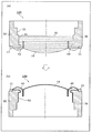
- FIG. 7 is a view for explaining a fluorine coating treatment method for an assembly in a state where the diaphragm and the support member are fixed to each other.
- the outer peripheral ring 11 of the diaphragm 10 is adhesively fixed to the front end of the support member 30.
- the diaphragm 10 closes the opening on the front side of the cylindrical support member 30. That is, the assembly 100 has a cylindrical shape having a bottom on one side. Therefore, the liquid fluorine coating agent 61 is injected into the bottomed cylindrical assembly 100 with the diaphragm 10 of the assembly 100 directed downward. At this time, the fluorine coating agent 61 is injected until the liquid surface of the fluorine coating agent 61 has a height near the boundary between the inner peripheral surface 31 in contact with the magnetic circuit 50 and the inner peripheral surface 32 not in contact with the magnetic circuit 50. . At this time, the fluorine coating agent 61 is injected until the liquid level becomes higher than the voice coil 40.
- the surface on the front side from the boundary between the inner circumferential surface 31 and the inner circumferential surface 32 and the surface of the voice coil 40 are subjected to fluorine coating treatment
- the coating film 62 is formed.
- the fluorine coating process is not performed on the surface on the rear side from the boundary, the coating film 62 is not formed.
- FIG. 8 is a view for explaining a fluorine coating treatment method for an assembly in which the magnetic circuit and the stopper are fixed to each other.
- the assembly 101 is inserted into a bottomed cylindrical container 110 filled with a fluorine coating agent 61 with the stopper 20 directed downward.
- the liquid level of the fluorine coating agent 61 inside the container 110 is formed by the disc portion 53a and the cylindrical portion 53b of the yoke 53 of the magnetic circuit 50 in a state where the assembly 101 is in contact with the bottom of the container 110. It is located below the corner 53d.
- FIG. 8 is an enlarged view of the area of the first adhesive portion 22 and the second adhesive portion 23.
- the air gap causes the capillary action.
- the fluorine coating agent 61 penetrates. Thereby, when there is a minute space in the first adhesive portion 22 and the second adhesive portion 23, the coating film 63 is formed by performing the fluorine coating process also on the surface of the minute space. Ru.
- the surface of the portion on the front side of the end face 52d on the rear side of the magnet 52 of the assembly 101 is subjected to the fluorine coating process
- the coating film 63 is formed. Further, the coating film 63 is not formed because the fluorine coating process is not performed on a part of the rear side of the magnet 52 and the surfaces of the disc portion 53a and the corner portion 53d of the yoke 53.
- the fluorine coating process is performed by inserting the assembly 101 into the fluorine coating agent 61 filled in the container 110, the outer surface of the assembly 101 in the assembly 101, and the through holes 21, A coating film 63 is formed on the inner surfaces of 52a and 53c.
- the coating film 63 is formed on the surface of the plate 51 on which the magnetic fluid 60 is disposed and the portion bonded and bonded in the gap between the stopper 20 and the magnet 52 bonded and bonded to the plate 51. it can. Therefore, even if the magnetic fluid 60 intrudes into the joint portion of the plate 51 and the stopper 20 or the joint portion of the plate 51 and the magnet 52, leakage to the through holes 21 and 51a side is suppressed.
- the fluorine coating agent 61 may contain a fluorescent agent that emits light when receiving ultraviolet light. That is, the coating films 62 and 63 formed by performing the fluorine coating process may include a fluorescent member that emits light when receiving ultraviolet light.
- FIG. 9 is a view for explaining a method of adhesively bonding the assembly in which the coating film is formed by the fluorine coating process.
- the surface of the inner circumferential surface 32 of the assembly 100 is not subjected to the fluorine coating treatment, and thus no coating film is formed.
- the outer surface of the corner 53 d of the yoke 53 of the assembly 101 is not subjected to the fluorine coating treatment, and thus no coating film is formed. That is, the surface of the yoke 53 in the portion where the yoke 53 is supported by the support member 30 has a region in which the coating film 63 is not formed.
- the space between the inner circumferential surface 32 of the assembly 100 and the outer surface of the corner 53 d of the yoke 53 of the assembly 101 is filled with the adhesive 33 to form the inner circumferential surface 32 of the assembly 100 and The outer surface of the corner 53 d of the yoke 53 of the assembly 101 can be effectively fixed.
- the magnetic fluid 60 is a mixture of ferromagnetic fine particles such as iron oxide (Fe3O4), a dispersing agent such as an organic acid covering the surface of the ferromagnetic fine particles, and a solvent composed of a synthetic hydrocarbon-based oil such as poly alpha olefin. It is a magnetic colloid solution composed of
- the magnetic fluid 60 has a viscosity of more than 9 mPa ⁇ s and 500 mPa ⁇ s or less at a predetermined reference temperature (eg, normal temperature: 15 to 35 ° C.).
- the reference temperature may be 27 ° C., for example.
- the magnetic fluid 60 has a minimum value of viscosity of 9 mPa ⁇ s or more in a temperature range that exceeds the reference temperature. Further, the viscosity of the magnetic fluid 60 at the reference temperature is higher than the viscosity of the magnetic fluid 60 in the temperature range above the reference temperature.
- the magnetic fluid 60 has a magnetic saturation density of 22 mT or more.
- the magnetic saturation density is also referred to as saturation magnetization.
- FIG. 5 is a graph showing the relationship between temperature change and viscosity change of magnetic fluid having different viscosities at a reference temperature.
- the solid line graph in FIG. 5 shows the relationship between the temperature change and the viscosity change of the magnetic fluid having a viscosity of 500 mPa ⁇ s at a reference temperature of 27 ° C.
- the broken line graph in FIG. 5 shows the relationship between the temperature change and the viscosity change of the magnetic fluid having a viscosity of 2000 mPa ⁇ s at a reference temperature of 27 ° C.
- the viscosity decreases to 220 mPa ⁇ s when the temperature changes from 27 ° C. to 40 ° C., and the reduction width is 280 mPa ⁇ s. ⁇ S.
- the viscosity decreases to 900 mPa ⁇ s when the temperature changes from 27 ° C. to 40 ° C., and the reduction range is 1100 mPa ⁇ s .
- the magnetic fluid having the viscosity of 500 mPa ⁇ s has a significantly smaller decrease in the viscosity with respect to the temperature increase as compared with the magnetic fluid having the viscosity of 2000 mPa ⁇ s. Further, as the magnetic fluid has a lower viscosity at the reference temperature, the decrease in viscosity with respect to the temperature rise becomes smaller. For this reason, if the magnetic fluid has a viscosity of 500 mPa ⁇ s or less, it is possible to effectively suppress the decrease in viscosity with respect to the temperature rise.
- the solvent used for the magnetic fluid 60 is oxidatively degraded when it exceeds 130 ° C. Therefore, the magnetic fluid 60 is preferably used in a temperature range of 130 ° C. or less.
- the magnetic fluid having a viscosity of 500 mPa ⁇ s at a reference temperature of 27 ° C. monotonously decreases as the temperature rises, and the viscosity at 130 ° C. is 9 mPa ⁇ s. Therefore, as for the viscosity of the magnetic fluid 60, it is preferable that the minimum value in the temperature range of 130 degrees C or less and larger than a reference temperature is 9 mPa * s or more.
- FIG. 6 is a graph showing frequency characteristics of output sound pressure of speakers using magnetic fluids having different viscosities at a reference temperature. Specifically, the solid line graph in FIG. 6 shows the frequency characteristic of the output sound pressure of the speaker when using the magnetic fluid having a viscosity of 500 mPa ⁇ s at a reference temperature of 27 ° C. The broken line graph of FIG. 6 shows the frequency characteristic of the output sound pressure of the speaker when using a magnetic fluid having a viscosity of 2000 mPa ⁇ s at a reference temperature of 27 ° C.
- a speaker using a magnetic fluid having a viscosity of 500 mPa ⁇ s at a reference temperature of 27 ° C. is substantially more than a speaker using a magnetic fluid having a viscosity of 2000 mPa ⁇ s at a reference temperature of 27 ° C.
- Output sound pressure is large across all frequencies. For this reason, the speaker using the magnetic fluid having a small viscosity can improve the frequency characteristic of the output sound pressure.
- a coating film containing a fluorine resin is formed on the surface of the outer peripheral edge 51 b of the plate 51 and the surface of the voice coil 40.
- the coating film 63 is formed on the surface of the recess formed by the yoke 53, the magnet 52 and the plate 51. Therefore, the surface energy of the surfaces of the yoke 53, the magnet 52 and the plate 51 can be reduced, and the magnetic fluid 60 can be prevented from being drawn between the yoke 53, the magnet 52 and the plate 51 by capillary action.
- the coating film 62 is formed on the surface of the diaphragm 10 on which the voice coil 40 is disposed and the surface of the voice coil 40. Therefore, even if capillary action with respect to the magnetic fluid 60 occurs when the voice coil 40 or the diaphragm 10 approaches the surface of the magnetic circuit 50, the magnetic fluid 60 is located at a distance from the plate 51 and the voice coil 40. It is possible to reduce movement. For this reason, it is possible to effectively prevent the magnetic fluid 60 from being dissipated.
- the surface of the portion where the yoke 53 is supported by the support member 30 has a region in which the coating film is not formed. Therefore, the yoke 53 and the support member 30 can be effectively adhered and fixed.
- the coating films 62, 63 further include a fluorescent member that emits light when receiving ultraviolet light.
- the coating film 62, 63 to which the fluorine coating process was performed by projecting an ultraviolet light on the surface of each assembly 100, 100 after the fluorine coating process is performed and the coating films 62 and 63 are formed. It is possible to confirm the formation state of Therefore, it is possible to form good coating films 62, 63.
- each assembly 100, 100 after the fluorine coating process has been performed it is possible to confirm locations and areas where the fluorine coating process has not been performed. Therefore, it can be confirmed that the coating film is not formed as in the case where the yoke 53 is supported by the support member 30.
- the second portion 22 b of the first adhesive portion 22 covers the outlet of the gap between the plate 51 and the joint surface of the magnet 52. Therefore, even when the magnetic fluid 60 intrudes into the gap, the second portion 22b suppresses the leakage of the magnetic fluid 60 from the outlet of the gap. Thus, the speaker 1 suppresses the decrease of the magnetic fluid 60 from the magnetic air gap 54.
- the second portion 22 b of the first adhesive portion 22 is a gap adjacent to the corner of the plate 51 and the magnet 52 in the gap between the joining surface of the plate 51 and the magnet 52. Close the exit.
- the second portion 22b located at the corner can effectively close and seal the outlet of the gap.
- the stopper 20 covers the outlet of the gap between the plate 51 and the joint surface of the magnet 52 and the second portion 22 b of the first adhesive portion 22 to form the plate 51 and the magnet 52. Adhesively bonded. For this reason, the stopper 20 can suppress the leakage of the magnetic fluid 60 through the outlet of the gap and the second portion 22b.
- the second adhesive portion 23 covers the whole of the second portion 22 b of the first adhesive portion 22, thereby suppressing leakage of the magnetic fluid 60 through the second portion 22 b. be able to.
- the stopper 20 forms the sealing space 55 for housing the second portion 22 b of the first adhesive portion 22 together with the plate 51 and the magnet 52.
- the second portion 22 b can be formed in a lump in accordance with the shape of the sealing space 55.
- the second portion 22 b can cover and seal the entire exit of the gap between the plate 51 and the joint surface of the magnet 52 with a sufficient thickness.
- the plate 51 is distal to the outlet of the gap on the inner circumferential surface of the through hole 51 a of the plate 51 adjacent to the outlet of the gap between the plate 51 and the joint surface of the magnet 52. It has a corner at the end.
- the stopper 20 has a shape that fits into the corner, and the second adhesive portion 23 extends across the corner of the plate 51. For this reason, even when the magnetic fluid 60 intrudes into the gap between the plate 51 and the stopper 20, it becomes difficult for the infiltration to proceed at the corner. Thus, the progress of the intrusion of the magnetic fluid 60 is suppressed.
- the second adhesive constituting the second adhesive portion 23 is a visible light curable adhesive, and the stopper 20 has translucency, so the second adhesive Reliable and quick curing of the
- the second adhesive constituting the second adhesive portion 23 contains a fluorescent agent that emits light when receiving ultraviolet light, the second adhesive after joining of the members is used. By projecting ultraviolet light, it is possible to check the adhesion state of the second adhesive. Thus, it is possible to form a good second adhesive portion 23.
- the viscosity of the magnetic fluid 60 at a predetermined reference temperature is more than 9 mPa ⁇ s and 500 mPa ⁇ s or less. Further, the minimum value of the viscosity of the magnetic fluid 60 in a temperature range (for example, a temperature range of more than 27 ° C. and 130 ° C. or less) exceeding the reference temperature is 9 mPa ⁇ s or more. Further, the viscosity of the magnetic fluid 60 at the reference temperature is larger than the viscosity of the magnetic fluid 60 in the temperature range. Thereby, even if the temperature rises, the decrease in viscosity can be suppressed. Therefore, it is possible to realize a speaker capable of stably maintaining the output sound pressure.
- the magnetic saturation density of the magnetic fluid 60 is 22 mT or more. Therefore, even with the magnetic fluid 60 having a small viscosity, the attractive force can be maximized by the magnetic force of the magnetic circuit 50, and therefore, the magnetic fluid 60 can be effectively retained in the magnetic gap 54 of the magnetic circuit 50. Thus, the influence of capillary action on the magnetic fluid 60 can be reduced.
- the coating film 62 is formed on the surface of the outer peripheral edge 51b of the plate 51 and the surface on the inner peripheral side of the voice coil 40.
- the coating film is formed on only one of the surfaces. It is good also as composition formed.
- the surface of the portion of the plate and the voice coil in contact with the magnetic fluid may be fluorine-coated, and the configuration is not limited to the above.
- the coating film 62 is formed on the surface on the front side of the boundary between the inner circumferential surface 31 and the inner circumferential surface 32 and the surface of the voice coil 40, but the present invention is not limited thereto.
- the surface of the diaphragm 10 on which the voice coil 40 is disposed may be formed at least at the joint of the voice coil 40 and the diaphragm 10 and the surface of the voice coil 40. That is, the coating film 62 may be formed on the surface on the rear side of the diaphragm 10 and on the surface of the predetermined range from the junction with the voice coil 40 and the surface of the voice coil 40.
- the coating film 63 is formed on the surface of the front side of the rear end surface 52d of the magnet 52 of the assembly 101.
- the present invention is not limited to this. 53, and may be formed on the surface of the recess (magnetic air gap 54) formed by the magnet 52 and the plate 51.
- the speaker according to the second embodiment is a speaker having an external magnet type magnetic circuit.
- FIG. 12 is a perspective view showing the appearance of the loudspeaker of the second embodiment.
- FIG. 13 is an exploded perspective view of the loudspeaker according to the second embodiment.
- FIG. 14 is a cross-sectional view of the speaker of FIG. 12 taken along line XIV-XIV.
- FIG. 15 is an XV-XV cross-sectional view of the speaker of FIG.
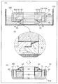
- FIG. 16 is a cross-sectional view taken along line XIV-XIV of the speaker of FIG. 12 after the fluorine coating process.
- FIG. 17 is an XV-XV cross-sectional view of the speaker of FIG. 12 after the fluorine coating process.
- FIGS. 14 to 17 are diagrams showing the configuration on the left side of the central axis of the speaker in the cross-sectional view.
- the speaker 1A includes a diaphragm 10A, a support member 30A, a voice coil 40A, a plate 51A, a magnet 52A, a yoke 53A, and a magnetic fluid 60, as shown in FIGS. That is, an external magnet type magnetic circuit is formed by the plate 51A, the magnet 52A, the yoke 53A, and the magnetic fluid 60.
- the speaker 1A may further include a spacer 70, a substrate 80, and a dustproof net 90.
- substrate 80, and the dustproof net 90 are the same as that of the structure of the speaker 1 which concerns on Embodiment 1, description is abbreviate
- the diaphragm 10A has a thin disk shape. Like the diaphragm 10 of the first embodiment, the diaphragm 10A includes the diaphragm body 12A and the diaphragm edge 13A.
- the diaphragm 10A of the second embodiment differs from the diaphragm 1 of the first embodiment in that the radial width of the diaphragm edge 13A is equal to the radial width of the diaphragm body 12A.
- the other configuration of the diaphragm 10A is the same as that of the diaphragm 10, and thus the description thereof is omitted. As shown by thick lines in FIGS. 16 and 17, a coating film 62A containing a fluorine resin is formed on the surface on the rear side of the diaphragm 10A.
- the support member 30A is a cylindrical member, and supports the diaphragm 10A at its front end.
- the supporting member 30A differs from the supporting member 30 according to the first embodiment in that the supporting member 30A has a projecting portion 31A projecting in the bulging direction (that is, the front side) of the diaphragm edge 13A of the diaphragm 10A as shown in FIG. .
- the protrusion 31 ⁇ / b> A may, for example, protrude further forward than the outer peripheral ring 11.
- the protrusion 31A is a member for preventing the diaphragm 10A from coming too close to the plate 51A, and has the same function as the stopper 20 of the first embodiment.
- the protrusion 31A can prevent the diaphragm 10A from approaching the plate 51A and the magnetic fluid 60 from coming into contact with the inner surface of the diaphragm 10A.
- the magnetic fluid 60 can be prevented from being separated from the space between the voice coil 40A and the yoke 53A by the contact of the inner surface of the diaphragm 10A.
- Support member 30A has a coating including a fluorine resin on the surface of the region between the portion supporting outer peripheral ring 11 and the portion contacting plate 51A, as shown by the thick lines in FIGS. A membrane 62A is formed.
- the plate 51A is a metal member having a circular plate shape and having a through hole 51Aa at the center. As shown by thick lines in FIGS. 16 and 17, a coating film 63A containing a fluorine resin is formed on the surface of the plate 51A excluding the surface facing the end face of the magnet 52A on the side of the S pole.
- the plate 51A is made of a magnetic material.
- the magnet 52A is a permanent magnet having a circular plate shape and a through hole 52Aa formed at the center.
- the plate 51A is fixed to one end surface 52Ac of the magnet 52A in the thickness direction (front-rear direction), and the yoke 53A is fixed to the end surface 52Ad opposite to the end surface 52Ac.
- the end face 52Ac is a south pole, and the end face 52Ad is a north pole.
- the present invention is not limited to the above configuration, and the end face 52Ac may be an S pole and the end face 52Ad may be an N pole.
- the magnet 52A is coaxially disposed with the plate 51A.
- the outer diameter of the magnet 52A may be larger than the outer diameter of the plate 51A. Further, the inner diameter of the through hole 52Aa of the magnet 52A is larger than the inner diameter of the through hole 51Aa of the plate 51A.
- the plate 51A, the magnet 52A and the yoke 53A are fixed to each other by an adhesive.
- the plate 51A, the magnet 52A, and the yoke 53A may not necessarily be fixed with an adhesive, and may be fixed using a fastening member such as a screw or a rivet.
- a coating film 63A containing a fluorine resin is formed on the surface of the through hole 52Aa of the magnet 52A as indicated by thick lines in FIGS.
- the yoke 53A has a disc portion 53Aa having a circular plate shape and a through hole 53Ac formed at the center, and a cylindrical tubular portion 53Ab erected on the disc portion 53Aa from the inner peripheral edge of the disc portion 53Aa. Have.
- the surface of the yoke 53A on the side where the cylindrical portion 53Ab of the disk portion 53Aa is formed is fixed to the end surface 52Ad of the magnet 52A.
- the cylindrical portion 53Ab of the yoke 53A is disposed inward of the through hole 52Aa of the magnet 52A, penetrates the magnet 52A, and is not in contact with the through hole 52Aa of the magnet 52A.
- the magnet 52A is disposed to cover the outside of the cylindrical portion 53Ab of the yoke 53A, and a cylindrical space is formed between the magnet 52A and the cylindrical portion 53Ab.
- the disc portion 53Aa of the yoke 53A is disposed coaxially with the magnet 52A.
- the cylindrical portion 53Ab of the yoke 53A extends so as to penetrate the through hole 51Aa of the plate 51A. That is, cylinder part 53Ab has the opposing part facing the inner surface of penetration hole 51Aa of plate 51A.
- a magnetic air gap 54A is formed between the cylindrical portion 53Ab and the plate 51A.
- the yoke 53A is made of a magnetic material.
- the cylindrical portion 53Ab of the yoke 53A protrudes further forward than the plate 51A.
- the cylindrical portion 53Ab has the same function as the stopper 20 of the first embodiment. That is, the cylindrical portion 53Ab can prevent the diaphragm 10A from approaching the plate 51A and the magnetic fluid 60 from coming into contact with the inner surface of the diaphragm 10A.
- the magnetic fluid 60 can be prevented from being separated from the space between the voice coil 40A and the yoke 53A by the contact of the inner surface of the diaphragm 10A.
- a coating film 63A containing a fluorocarbon resin is formed.
- the plate 51A, the magnet 52A, and the yoke 53A constitute an external magnet type magnetic circuit 50A. Since the magnetic circuit 50A is an external magnet type, the yoke 53A can be disposed on the inner periphery of the magnet 52A. Therefore, the configuration of the magnetic circuit 50A can be made smaller than that of the internal magnet type.
- the voice coil 40A is a coil-shaped member configured by winding a metal wire in a ring shape (cylindrical shape) a plurality of times.
- the voice coil 40A has input terminals 41A and 42A to which an electrical signal is input.
- the voice coil 40A is fixed to the diaphragm 10A. Specifically, the voice coil 40A is fixed to a portion inside the outer peripheral edge of the diaphragm 10A.
- the voice coil 40A is disposed in the magnetic air gap 54A of the magnetic circuit 50A.
- a coating film containing a fluorine resin is formed on the surface on the inner circumferential side and the surface on the outer circumferential side of the voice coil 40A.
- the magnetic fluid 60 is disposed between the facing portion of the cylindrical portion 53Ab of the magnetic circuit 50A and the voice coil 40A.
- the magnetic fluid 60 is disposed from the outer peripheral surface of the cylindrical portion 53Ab to the inner peripheral surface of the voice coil 40A. That is, the magnetic fluid 60 is disposed in a state in which the cylindrical portion 53Ab and the voice coil 40A are suspended.
- the magnetic fluid 60 is arrange
- the material constituting the magnetic fluid 60 is the same as that of the first embodiment.
- the support member 30A has the protrusion 31A for preventing the diaphragm 10A from coming too close to the plate 51A.
- the plate 51A may be configured to have a forwardly projecting protrusion for preventing the diaphragm 10A from coming too close to the plate 51A.
- both the support member 30A and the plate 51A may have a forwardly projecting protrusion for preventing the diaphragm 10A from coming too close to the plate 51A.
- the protrusion is made of the same material as the plate 51A, and may be a part integrally formed with the plate 51A, or made of a material different from the plate 51A. , Or a member fixed on the plate 51A.
- FIG. 18 is an external view showing an earphone using the speaker according to the embodiment.
- FIG. 19 is an exploded perspective view of the earphone.
- the earphone 200 includes a speaker 1, a port 2, an ear tip 3, a box 4, a cable 5, and a back cover 6.
- the earphone 200 is an inner-ear type headphone.
- the speaker 1A may be used instead of the speaker 1.
- the speaker 1 has the configuration described in the above embodiment.
- the port 2 is a substantially cylindrical member that accommodates the speaker 1 therein.
- the ear tip 3 is a member connected to the tip of the port 2 for disposing the earphone 200 inside a person's ear canal.
- the box 4 is a member for closing the opening on the side opposite to the side where the ear tip 3 of the port 2 is disposed.
- the port 2 and the box 4 form a housing for housing the speaker 1.
- the cable 5 is a member which penetrates the box 4, is connected to the substrate 80 of the speaker 1, and is for inputting an electrical signal to the speaker 1.
- the back cover 6 is a member that covers a portion where the cable 5 passes through the box 4.
- the sound output from the speaker 1 in accordance with the electrical signal input through the cable 5 is output from the port 2 and the ear tip 3. Therefore, when the ear tip 3 is attached to a person's external ear canal, the person can hear the sound from the earphone 200.
- the earphone 200 is an example of an audio device.
- the speaker 1 demonstrated the example used for inner-ear type headphones in the said usage example, you may be used for audio equipment, such as overhead type headphones, a portable terminal, or a hearing aid.
- the loudspeaker 1 may be used in a hearing aid.
- the present disclosure is useful as a speaker or the like that can effectively improve the characteristics.
Landscapes
- Physics & Mathematics (AREA)
- Engineering & Computer Science (AREA)
- Acoustics & Sound (AREA)
- Signal Processing (AREA)
- Health & Medical Sciences (AREA)
- General Health & Medical Sciences (AREA)
- Neurosurgery (AREA)
- Otolaryngology (AREA)
- Audible-Bandwidth Dynamoelectric Transducers Other Than Pickups (AREA)
Abstract
ヨーク(53)と、ヨーク(53)に固定されるマグネット(52)と、マグネット(52)のヨーク(53)と固定されている端面(52d)とは反対側の端面(52c)に固定されるプレート(51)と、ヨーク(53)とプレート(51)とのそれぞれに設けられ、互いに対向して配置された対向部同士の間に形成された磁気空隙(54)内に配置されるボイスコイル(40)と、ボイスコイル(40)に固定される振動板(10)と、ヨーク(53)および振動板(10)を支持する支持部材(30)と、プレート(51)の対向部とボイスコイル(40)との間に配置される磁性流体(60)と、を備え、プレート(51)およびボイスコイル(40)の少なくとも一方のうち、磁性流体(60)が接触する部位の表面には、フッ素樹脂を含むコーティング膜が形成されている。
Description
本開示は、磁性流体を備えるスピーカ、および、当該スピーカを備える音響装置に関する。
従来、特許文献1には、磁性流体を用いたスピーカが開示されている。磁性流体は、磁気回路が有する磁気ギャップ内に配置されるボイスコイルと、当該磁気回路を構成するプレートとの間に配置されている。このように、従来のスピーカでは、ボイスコイルとプレートとの間に磁性流体を配置することで、ボイスコイルの振動の安定化を図っている。
上記従来のスピーカでは、歪み特性を効果的に向上させることができていなかった。
そこで、本開示は、歪み特性を効果的に向上させることができるスピーカを提供する。
本開示の一態様に係るスピーカは、ヨークと、前記ヨークに固定されるマグネットと、前記マグネットの前記ヨークと固定されている面とは反対側の面に固定されるプレートと、前記ヨークと前記プレートとのそれぞれに設けられ、互いに対向して配置された対向部同士の間に形成された磁気空隙内に配置されるボイスコイルと、前記ボイスコイルに固定される振動板と、前記ヨークおよび前記振動板を支持する支持部材と、前記プレートの対向部と前記ボイスコイルとの間に配置される磁性流体と、を備え、前記プレートおよび前記ボイスコイルの少なくとも一方のうち、前記磁性流体が接触する部位の表面には、フッ素樹脂を含むコーティング膜が形成されている。
本開示の一態様に係るイヤホンは、上記スピーカを備える。
本開示に係るスピーカは、歪み特性を効果的に向上させることができる。
(本開示の基礎となった知見)
本発明者は、「背景技術」の欄において記載したスピーカに関し、以下の問題が生じることを見出した。
本発明者は、「背景技術」の欄において記載したスピーカに関し、以下の問題が生じることを見出した。
特許文献1に開示されているような従来のスピーカでは、磁性流体が接触するボイスコイルおよびプレートの表面には、振動板による風圧によって磁性流体が飛散することを防ぐために、磁性流体との間で表面エネルギーを小さくするような表面処理を行っていなかった。このため、ボイスコイルおよびプレートの表面と磁性流体との間の表面エネルギーを十分に小さくすることで、スピーカの歪み特性を向上させる余地があった。
また、特許文献1のスピーカの磁気回路は、ヨーク、マグネットおよびプレートが積層された状態で、接着剤などで互いに固定されることにより構成されている。マグネットは、厚み方向の両側の面で切断されることで構成されており、その切断面に微小な反りが生じている。また、プレートは、プレス成形で形成されるため、プレスによる微小な反りが生じている。このように、磁気回路を構成する部品のそれぞれの接着面には、微小な反りが生じているため、これらの部品を接着剤を用いて重ね合わせたときに、間に空気を含んだ状態となる。よって、ヨーク、マグネットおよびプレートは、それぞれの間に微小な隙間が生じた状態で接着固定されてしまう。
このように、磁気回路は隙間を有しており、かつ、磁性流体は当該磁気回路を構成するプレートとボイスコイルとの間に配置されている。このため、磁性流体は、磁気回路の隙間に毛細管現象によって引き込まれやすい状況にある。
さらに、磁性流体が配置されているボイスコイルは、電圧が印加されるとジュール熱を発生する。このため、磁性流体は、ボイスコイルからのジュール熱による影響を受けやすく、温度変化しやすいため、粘度が大きく変化しやすい。そして、磁性流体の粘度が大きく変化すると、上記の毛細管現象は、生じやすくなるという課題もある。
そこで、本開示の一態様に係るスピーカは、ヨークと、前記ヨークに固定されるマグネットと、前記マグネットの前記ヨークと固定されている面とは反対側の面に固定されるプレートと、前記ヨークと前記プレートとのそれぞれに設けられ、互いに対向して配置された対向部同士の間に形成された磁気空隙内に配置されるボイスコイルと、前記ボイスコイルに固定される振動板と、前記ヨークおよび前記振動板を支持する支持部材と、前記プレートの対向部と前記ボイスコイルとの間に配置される磁性流体と、を備え、前記プレートおよび前記ボイスコイルの少なくとも一方のうち、前記磁性流体が接触する部位の表面には、フッ素樹脂を含むコーティング膜が形成されている。
これにより、プレートおよびボイスコイルの少なくとも一方と、磁性流体との間の表面エネルギーを低減することができ、振動板をよりスムーズに振動させることができる。このため、スピーカの歪み特性を向上させることができる。
また、前記コーティング膜は、前記ヨーク、前記マグネットおよび前記プレートにより形成された凹部の表面に形成されていてもよい。
このため、ヨーク、マグネットおよびプレートの表面の表面エネルギーを小さくでき、ヨーク、マグネットおよびプレートの間に磁性流体が毛細管現象により引き込まれることを低減することができる。
また、前記コーティング膜は、前記振動板の前記ボイスコイルが配置されている側の表面において少なくとも前記ボイスコイルと前記振動板との接合部と、前記ボイスコイルの表面に形成されていてもよい。
このため、ボイスコイルまたは振動板が磁気回路の表面に近づくことにより、磁性流体に対する毛細管現象が発生したとしても、磁性流体がプレートおよびボイスコイルの間から離れた位置に移動することを低減することができる。このため、磁性流体が散逸することを効果的に防ぐことができる。
また、前記ヨークが前記支持部材に支持されている部分の前記ヨークの表面は、前記コーティング膜が形成されていない領域を有してもよい。
このため、ヨークと支持部材とを効果的に接着固定することができる。
また、前記コーティング膜は、さらに、紫外光を受けると発光する蛍光部材を含んでもよい。
このため、コーティング膜が形成された後の表面に紫外光を投射することによって、コーティング膜の形成状態の確認が可能である。よって、良好なコーティング膜を形成することが可能である。
また、さらに、前記プレートおよび前記マグネットを接着接合している第一接着剤部分を備え、前記第一接着剤部分は、前記プレートおよび前記マグネットの接合面の間隙内で第一接着剤が硬化した第一部分と、前記間隙の外で前記第一接着剤が硬化した第二部分とを含み、前記第二部分は、前記磁性流体へ向かう向きと異なる向きの前記間隙の出口を覆って形成されていてもよい。
これによれば、第一接着剤部分の第二部分は、プレート及びマグネットの接合面の間隙の出口を覆う。このため、当該間隙に磁性流体が侵入した場合であっても、第二部分は、間隙の当該出口から磁性流体が漏出することを抑える。よって、磁性流体の減少が抑えられる。
また、前記ヨークは、前記プレートの表面と前記マグネットの表面とが形成する隅部に位置し、前記隅部は、前記間隙の出口に隣接してもよい。
これによれば、第一接着剤部分の第二部分は、プレート及びマグネットの隅部に隣接する間隙の出口を塞ぐ。隅部に位置する第二部分は、間隙の出口を効果的に塞ぎ、封止することができる。
また、前記プレートおよび前記マグネットと接合される接合部材と、前記プレートおよび前記マグネットと前記接合部材とを接着接合している第二接着剤部分とをさらに備え、前記接合部材は、前記間隙の出口および前記第二部分を覆って配置されてもよい。
これによれば、接合部材は、間隙の出口及び第一接着剤部分の第二部分を覆って、プレート及びマグネットと接着接合されるため、間隙の出口及び第二部分を通じた磁性流体の漏出を抑えることができる。
また、前記第二接着剤部分は、前記ヨークの全体を覆ってもよい。
これによれば、第二接着剤部分は、第一接着剤部分の第二部分を通じた磁性流体の漏出を抑えることができる。
また、前記接合部材は、前記ヨークを収める空間を、前記プレート及び前記マグネットと共に形成してもよい。
これによれば、第一接着剤部分の第二部分は、当該空間の形状に合わせて、塊状に形成されることができる。よって、第二部分は、間隙の出口全体を十分な厚さで覆い封止することができる。
また、前記プレートは、前記間隙の出口に隣接する表面における前記間隙の出口から遠位の端部に、角部を有し、前記接合部材は、前記プレートの前記角部に嵌まる形状を有し、前記第二接着剤部分は、前記プレートの前記角部を跨いで延びてもよい。
これによれば、第二接着剤部分は、プレートの角部を跨いで延びる。このため、磁性流体は、プレート及び接合部材の間隙に侵入した場合であっても、角部において、侵入を進行することが困難になる。よって、磁性流体の侵入の進行が抑えられる。
また、前記第二接着剤部分を構成する第二接着剤は、可視光硬化型接着剤であり、前記接合部材は、透光性を有してもよい。
これによれば、第二接着剤の確実且つ迅速な硬化が可能になる。
また、前記第二接着剤部分を構成する第二接着剤は、紫外光を受けると発光する蛍光剤を含んでもよい。
これによれば、部材の接合後の第二接着剤に紫外光を投射することによって、第二接着剤の付着状態の確認が可能である。よって、良好な第二接着剤部分を形成することが可能である。
また、特許文献1に開示されているような従来のスピーカでは、振動板による風圧によって磁性流体が飛散することを防ぐために、基準温度(例えば27℃)における粘度が例えば4000mPa・sのような粘度が大きな磁性流体を用いていた。一般的に、磁性流体に用いられる溶媒(油)は、粘度が大きいほど、温度変化による粘度の変化幅が大きくなる。つまり、従来のスピーカに使用されている磁性流体は、温度が変化すると粘度も大きく変化する特性を有する。
ところで、スピーカは、磁性流体の粘度の大きさに応じて、出力音圧が変化する。つまり、温度が変化すると磁性流体の粘度の大きさが変化するため、スピーカの出力音圧が変化するという課題がある。
また、磁性流体が配置されているボイスコイルは、電圧が印加されるとジュール熱を発生する。このため、磁性流体は、ボイスコイルからのジュール熱による影響を受けやすく、温度変化しやすいため、粘度が大きく変化しやすい。
このように、磁性流体を用いた従来のスピーカでは、出力音圧を安定して維持することが難しいという課題があった。
また、上記で説明したような、磁性流体が磁気回路の隙間に毛細管現象によって引き込まれやすい状況下において、粘度が大きな磁性流体では、温度上昇によって粘度が低下する低下幅が大きいため、毛細管現象による影響を受けやすくなる。毛細管現象による影響は、粘度の低下幅が大きいほど大きいため、毛細管現象による影響を考慮すれば、磁性流体の粘度が小さいことが好ましい。つまり、本発明者は、磁性流体の散逸を抑制するために、粘度が小さい磁性流体を用いることに至った。
つまり、本開示の一態様に係るスピーカは、ヨークと、前記ヨークに固定されるマグネットと、前記マグネットの前記ヨークと固定されている面とは反対側の面に固定されるプレートと、前記ヨークと前記プレートとのそれぞれに設けられ、互いに対向して配置された対向部同士の間に形成された磁気空隙内に配置されるボイスコイルと、前記ボイスコイルに固定される振動板と、前記ヨークおよび前記振動板を支持する支持部材と、前記プレートの対向部と前記ボイスコイルとの間に配置される磁性流体と、を備え、所定の基準温度における前記磁性流体の粘度は、9mPa・sより大きく500mPa・s以下であり、前記基準温度を超えた温度範囲における前記磁性流体の粘度の極小値は、9mPa・s以上であり、前記基準温度における前記磁性流体の粘度は、前記温度範囲における前記磁性流体の粘度よりも大きい。
これによれば、所定の基準温度における粘度が9mPa・sより大きく500mPa・s以下の磁性流体を用いるため、温度上昇した場合であっても、粘度の低下幅を抑えることができる。このため、出力音圧を安定して維持することができるスピーカを実現できる。
また、前記磁性流体の磁気飽和密度は、22mT以上であってもよい。
このため、粘度が小さい磁性流体であっても、磁力により引力を極力大きくすることができるため、磁気回路の磁気空隙内に効果的に留まらせることができる。よって、磁性流体への毛細管現象による影響を低減することができる。
スピーカの音質を向上するために、磁気回路に磁性流体が配置された技術が提案されている。例えば、特許文献1に開示されるスピーカは、マグネットと、マグネットに接続されたヨーク及びプレートと、ヨーク及びプレートの間の磁気空隙内に配置されたボイスコイルとを備える。ボイスコイルは、振動板と接合されている。さらに、当該スピーカは、プレートとボイスコイルとの間に磁性流体を備える。磁性流体は、ボイスコイルをプレートに対して支持する。
特許文献1に開示されるスピーカにおいて、磁性流体は、毛細管現象によって、プレートとマグネットとの間のような部材間の間隙に侵入し、間隙から外部に漏れ出す可能性がある。これにより、ボイスコイルを支持する磁性流体の量が減少するため、磁性流体におけるボイスコイルを支持する機能が低下し、スピーカに異常が生じる可能性がある。
特許文献1に記載されるスピーカでは、磁性流体は、プレートの縁に配置される。さらに、このプレートの縁は、プレートとマグネットとの接合面の近傍に位置している。音波の発生時にボイスコイルが振動することによって、磁性流体も振動し、これにより、磁性流体が上記接合面に接する。このとき、磁性流体の表面張力により、磁性流体に毛細管現象が発生し、磁性流体が接合面の間隙に侵入することがある。侵入した磁性流体は、例えば、磁性流体と反対側に位置する間隙の出口から漏出する。これにより、磁気空隙内の磁性流体が減少し、磁性流体の機能が低下する。そこで、本発明者らは、上述のような磁性流体の減少を抑えるために、以下に示す技術を創案した。
本開示の一態様によるスピーカは、マグネットと、第一対向部を有し、前記マグネットの第一の磁極と磁気的に結合された第一部材と、前記第一対向部と対向し且つ前記第一対向部の外方に配置された第二対向部を有し、前記マグネットの前記第一の磁極の反対の第二の磁極と磁気的に結合された第二部材と、前記第一対向部及び前記第二対向部の間に形成された磁気空隙に配置されるボイスコイルと、前記ボイスコイルと前記第一対向部との間に少なくとも配置される磁性流体と、前記第一部材及び前記マグネットを接着接合している第一接着剤部分とを備え、前記第一接着剤部分は、前記第一部材及び前記マグネットの接合面の間隙内で第一接着剤が硬化した第一部分と、前記間隙の外で前記第一接着剤が硬化した第二部分とを含み、前記第二部分は、前記磁性流体へ向かう向きと異なる向きの前記間隙の出口を覆って形成されている。
上記態様によると、第一接着剤部分の第二部分は、第一部材及びマグネットの接合面の間隙の出口を覆う。このため、当該間隙に磁性流体が侵入した場合であっても、第二部分は、間隙の当該出口から磁性流体が漏出することを抑える。よって、磁性流体の減少が抑えられる。
本開示の一態様によるスピーカにおいて、前記第二部分は、前記第一部材の表面と前記マグネットの表面とが形成する隅部に位置し、前記隅部は、前記間隙の出口に隣接してもよい。上記態様によると、第一接着剤部分の第二部分は、第一部材及びマグネットの隅部に隣接する間隙の出口を塞ぐ。隅部に位置する第二部分は、間隙の出口を効果的に塞ぎ、封止することができる。
本開示の一態様によるスピーカは、前記第一部材及び前記マグネットと接合される第三部材と、前記第一部材及び前記マグネットと前記第三部材とを接着接合している第二接着剤部分とをさらに備え、前記第三部材は、前記間隙の出口及び前記第二部分を覆って配置されてもよい。上記態様によると、第三部材は、間隙の出口及び第一接着剤部分の第二部分を覆って、第一部材及びマグネットと接着接合されるため、間隙の出口及び第二部分を通じた磁性流体の漏出を抑えることができる。
本開示の一態様によるスピーカにおいて、前記第二接着剤部分は、前記第二部分の全体を覆ってもよい。上記態様によると、第二接着剤部分は、第一接着剤部分の第二部分を通じた磁性流体の漏出を抑えることができる。
本開示の一態様によるスピーカにおいて、前記第三部材は、前記第二部分を収める空間を、前記第一部材及び前記マグネットと共に形成してもよい。上記態様によると、第一接着剤部分の第二部分は、当該空間の形状に合わせて、塊状に形成されることができる。よって、第二部分は、間隙の出口全体を十分な厚さで覆い封止することができる。
本開示の一態様によるスピーカにおいて、前記第一部材は、前記間隙の出口に隣接する表面における前記間隙の出口から遠位の端部に、角部を有し、前記第三部材は、前記第一部材の前記角部に嵌まる形状を有し、前記第二接着剤部分は、前記第一部材の前記角部を跨いで延びてもよい。上記態様によると、第二接着剤部分は、第一部材の角部を跨いで延びる。このため、磁性流体は、第一部材及び第三部材の間隙に侵入した場合であっても、角部において、侵入を進行することが困難になる。よって、磁性流体の侵入の進行が抑えられる。
本開示の一態様によるスピーカにおいて、前記第二接着剤部分を構成する第二接着剤は、可視光硬化型接着剤であり、前記第三部材は、透光性を有してもよい。上記態様によると、第二接着剤の確実且つ迅速な硬化が可能になる。
本開示の一態様によるスピーカにおいて、前記第二接着剤部分を構成する第二接着剤は、蛍光剤を含んでもよい。上記態様によると、部材の接合後の第二接着剤に蛍光剤を発光させる光を投射することによって、第二接着剤の付着状態の確認が可能である。よって、良好な第二接着剤部分を形成することが可能である。
また、本開示の一態様によるイヤホンは、上記スピーカを備える。上記態様によると、本開示の一態様によるスピーカと同様の効果が得られる。
また、本開示の一態様による補聴器は、上記スピーカを備える。上記態様によると、本開示の一態様によるスピーカと同様の効果が得られる。
また、本開示の一態様によると、携帯型端末装置は、上記スピーカを備える。上記態様によると、本開示の一態様によるスピーカと同様の効果が得られる。
また、本開示の一態様に係る音響装置は、上記スピーカと、前記スピーカを収納する筐体と、を備える。
上記態様によると、本開示の一態様によるスピーカと同様の効果が得られる。
以下、本開示の一態様に係るスピーカについて、図面を参照しながら具体的に説明する。
なお、以下で説明する実施の形態は、いずれも本開示の一具体例を示すものである。以下の実施の形態で示される数値、形状、材料、構成要素、構成要素の配置位置及び接続形態、処理、処理の順序などは、一例であり、本開示を限定する主旨ではない。また、以下の実施の形態における構成要素のうち、最上位概念を示す独立請求項に記載されていない構成要素については、任意の構成要素として説明される。また、以下の実施の形態の説明において、略平行、略直交のような「略」を伴った表現が、用いられる場合がある。例えば、略平行とは、完全に平行であることを意味するだけでなく、実質的に平行である、すなわち、例えば数%程度の差異を含むことも意味する。他の「略」を伴った表現についても同様である。また、各図は模式図であり、必ずしも厳密に図示されたものではない。さらに、各図において、実質的に同一の構成要素に対しては同一の符号を付しており、重複する説明は省略又は簡略化される場合がある。
(実施の形態1)
図1~図11を用いて、実施の形態1のスピーカについて説明する。実施の形態1に係るスピーカは、内磁型の磁気回路を有するスピーカである。
図1~図11を用いて、実施の形態1のスピーカについて説明する。実施の形態1に係るスピーカは、内磁型の磁気回路を有するスピーカである。
[1-1.構成]
図1は、実施の形態1に係るスピーカの外観を示す斜視図である。図2は、実施の形態1に係るスピーカの分解斜視図である。図3は、図1のスピーカのIII-III断面図である。図4は、図1のスピーカのIV-IV断面図である。
図1は、実施の形態1に係るスピーカの外観を示す斜視図である。図2は、実施の形態1に係るスピーカの分解斜視図である。図3は、図1のスピーカのIII-III断面図である。図4は、図1のスピーカのIV-IV断面図である。
スピーカ1は、図1~図4に示すように、振動板10と、支持部材30と、ボイスコイル40と、プレート51と、マグネット52と、ヨーク53と、磁性流体60とを備える。すなわち、プレート51と、マグネット52と、ヨーク53と、磁性流体60とによって内磁型の磁気回路が形成されている。スピーカ1は、さらに、ストッパ20と、スペーサ70と、基板80と、防塵ネット90とを備えていてもよい。なお、スピーカ1において、スピーカ1から音が放出される方向を前方とし、その反対方向を後方とする。
振動板10は、薄い円板形状を有している。振動板10は、前方から見た場合の中央付近が外周縁よりも前側に膨出した形状を有する。振動板10は、また、中央の円盤状の振動板ボディ12と、振動板ボディ12の外周を囲む円環状又はリング状の振動板エッジ13とを備える。振動板エッジ13は、可撓性を有し、振動板ボディ12は、振動板エッジ13よりも剛性を有する。振動板エッジ13の径方向の幅は、振動板ボディ12Aの径方向の幅よりも小さい幅を有する。振動板ボディ12の外周縁及び振動板エッジ13の内周縁は、互いに結合され、振動板ボディ12及び振動板エッジ13は一体化されている。振動板10は、振動板エッジ13の外周縁に外周リング11が設けられており、外周リング11が支持部材30に固定されることで、支持部材30に支持されている。振動板ボディ12は、その外周縁近傍でボイスコイル40と結合されている。これにより、ボイスコイル40が振動すると、振動板エッジ13が変形しつつ、振動板ボディ12及び振動板エッジ13が一緒に振動する。
また、振動板10の後方側の表面には、フッ素樹脂を含むコーティング膜が形成されていてもよい。なお、コーティング膜を形成するためのフッ素コート処理の詳細については後述する。
支持部材30は、円筒形状の部材であり、前側の端部で振動板10を支持している。支持部材30は、内部に、ストッパ20、ボイスコイル40、プレート51、マグネット52、ヨーク53および磁性流体60を収容する。支持部材30は、さらに、基板80および防塵ネット90を収容してもよい。基板80および防塵ネット90は、前後方向において、支持部材30の振動板10とは反対側の端部に配置されていてもよい。支持部材30は、例えば、金属、樹脂などにより構成される。
プレート51は、円形板状で中央に貫通孔51aが形成されている金属製の部材である。プレート51は、その一方の面がマグネット52のN極側の端面と対向した状態で当該端面に固定されている。プレート51の外周縁51bの表面には、フッ素樹脂を含むコーティング膜が形成されている。プレート51は、磁性体により構成される。ここで、プレート51は、第一部材の一例である。また、プレート51の外周縁51bは、第一対向部の一例である。
マグネット52は、円形板状で中央に貫通孔52aが形成されている永久磁石である。マグネット52は、厚み方向(前後方向)の一端がN極であり、他端がS極である。マグネット52は、上記とは反対に、一端がS極であり、他端がN極であってもよい。マグネット52のN極側の端面52cには、プレート51が固定されており、S極側の端面52dには、ヨーク53が固定されている。マグネット52は、プレート51と同軸上に配置される。マグネット52の外径は、プレート51の外径と同等である。このため、マグネット52の外周面52bとプレート51の外周縁51bとは略面一となる。なお、マグネット52の外径は、プレート51の外径よりも小さくてもよい。また、マグネット52の貫通孔52aの内径は、プレート51の貫通孔51aの内径よりも小さい。このため、貫通孔51a内において、マグネット52の端面52cの一部が、プレート51に覆われずに露出している。具体的には、プレート51、マグネット52およびヨーク53は、互いに接着剤により固定されている。なお、プレート51、マグネット52およびヨーク53は、必ずしも接着剤で固定されていなくてもよく、ネジ、リベットなどの締結部材を用いて固定されていてもよい。
ヨーク53は、円形板状で中央に貫通孔53cが形成されている円板部53aと、円板部53aの外周縁から円板部53aに立設されている円筒形状の筒部53bとを有する。ヨーク53は、円板部53aの筒部53bが形成されている側の面がマグネット52のS極側の端部と固定されている。ヨーク53の筒部53bは、マグネット52の外周面52bの側方を覆っており、マグネット52の外周面52bとは接触していない。マグネット52は、ヨーク53の筒部53bの内側に配置されており、筒部53bとの間に円筒形状の空間が形成されている。ヨーク53の円板部53aは、マグネット52の同軸上に配置される。ヨーク53の筒部53bは、マグネット52のN極側の端部に配置されているプレート51の側方まで延びている。つまり、筒部53bは、プレート51の第一対向部としての外周縁51bと対向する第二対向部の一例である。そして、筒部53bとプレート51との間には、磁気空隙54が形成されている。また、ヨーク53の筒部53bの外周面の一部は、支持部材30に支持されていてもよい。ヨーク53は、磁性体により構成される。ヨーク53は、第二部材の一例である。
このように、プレート51、マグネット52およびヨーク53は、内磁型の磁気回路50を構成している。
ストッパ20は、振動板10がプレート51に近づきすぎることを防ぐための部材である。ストッパ20は、プレート51よりも振動板10側に突出しており、かつ、振動板10の形状に沿った形状を有する。ストッパ20の突出している部分と、振動板10との間には隙間が形成されている。また、ストッパ20は、磁気回路50の貫通孔52a、53cと重なる位置に、これらの貫通孔52a、53cと略同一の形状の貫通孔21を有する。ストッパ20は、プレート51の一部およびマグネット52の端面52cの露出部分を覆うように配置される。ストッパ20は、プレート51およびマグネット52に接着剤により固定されている。ストッパ20は、無磁性の材料で構成され、例えば、樹脂で構成されている。また、ストッパ20は、可視光域の光を透過させることができるように構成され、例えば、半透明又は透明に作製される。ストッパ20の構成材料の例は、ポリカーボネート(「PC」とも呼ばれる)、アクリル樹脂(「PMMA」とも呼ばれる)等である。しかしながら、ストッパ20の構成材料は、可視光域の光を透過させることができ、且つ、後述する磁性流体60に対して耐性を有する材料であればよい。具体的には、ストッパ20の構成材料は、磁性流体60を構成する溶媒に対して耐性を有する材料であってもよい。溶媒に、下記の表1に示される油脂が使用される場合、ストッパ20の構成材料には、表1に示すような各油脂に耐性を有する材料が適用されてもよい。ストッパ20は、接合部材の一例である。また、ストッパ20は、第三部材の一例である。
なお、ストッパ20および磁気回路50の前側の一部の表面には、コーティング膜が形成されていてもよい。なお、当該コーティング膜を形成するためのフッ素コート処理の詳細は、後述する。

ボイスコイル40は、金属製の線材が複数回環状(円筒形状)に巻回されることにより構成されるコイル状の部材である。ボイスコイル40は、電気信号が入力される入力端子41、42を有する。ボイスコイル40は、振動板10と固定されている。具体的には、ボイスコイル40は、振動板10の外周縁よりも内側の部位に固定されている。ボイスコイル40は、磁気回路50の磁気空隙54内に配置されている。ボイスコイル40の内周側の表面には、フッ素樹脂を含むコーティング膜が形成されている。
磁性流体60は、磁気回路50のプレート51の対向部とボイスコイル40との間に配置される。磁性流体60は、プレート51の外周側の面からボイスコイル40の内周側の面までに亘って配置される。つまり、磁性流体60は、プレート51とボイスコイル40とを懸架した状態で配置される。また、磁性流体60は、プレート51の外周の全周に亘って環状に配置される。つまり、磁性流体60は、ボイスコイル40の内周の全周に亘って環状に配置される。磁性流体60は、酸化鉄(Fe3O4)などの強磁性微粒子と、強磁性微粒子の表面を覆う有機酸などの分散剤と、ポリαオレフィンなどの合成炭化水素系油からなる溶媒とを混合することで構成される磁性コロイド溶液である。
スペーサ70は、支持部材30、ヨーク53および基板80との間で空間を形成することで、音管を形成するための部材である。スペーサ70は、ヨーク53の円板部53aのマグネット52が配置される側とは反対側に配置される。
基板80は、円形板状で中央に貫通孔81が形成されている部材である。基板80は、ボイスコイル40の入力端子41、42と、外部からの電気信号を取得するための端子とを電気的に接続する回路を有する。当該回路は、外部から取得した電気信号を変換して、変換した電気信号をボイスコイル40の入力端子41、42に出力してもよい。基板80は、スペーサ70のヨーク53が配置される側とは反対側に配置される。
防塵ネット90は、基板80の貫通孔81を覆うネットである。防塵ネット90は、基板80のスペーサ70が配置される側とは反対側に配置される。
[1-2.接合部分の詳細構成]
次に、ストッパ20、プレート51及びマグネット52の接合部分の詳細を説明する。図5を参照すると、図3のスピーカ1におけるストッパ20、プレート51及びマグネット52の接合部分が、接着剤部分が形成されていない状態で拡大して示されている。また、図6を参照すると、図3のスピーカ1におけるストッパ20、プレート51及びマグネット52の接合部分が、接着剤部分が形成された状態で拡大して示されている。
次に、ストッパ20、プレート51及びマグネット52の接合部分の詳細を説明する。図5を参照すると、図3のスピーカ1におけるストッパ20、プレート51及びマグネット52の接合部分が、接着剤部分が形成されていない状態で拡大して示されている。また、図6を参照すると、図3のスピーカ1におけるストッパ20、プレート51及びマグネット52の接合部分が、接着剤部分が形成された状態で拡大して示されている。
図5に示すように、円環板状のプレート51は、貫通孔51aと外周縁51bとの間に、互いに反対方向に向いた2つの平坦な環状表面51c及び51dを有している。表面51dが、マグネット52の端面52cに対向するように、プレート51は配置されている。ストッパ20は、表面51c、貫通孔51aの内周面及び端面52cにわたって、プレート51及びマグネット52を覆うように配置されている。ストッパ20は、表面51c及び貫通孔51aの内周面の形状に倣う形状の表面20bを有し、表面20bは、表面51c及び貫通孔51aの内周面が形成する角部に密接に嵌まる。表面20bは、環状であり、L字状に窪んだ径方向断面を有する。ここで、表面51c及び貫通孔51aの内周面が形成する角部は、プレート51及びマグネット52の間の間隙の出口に隣接する貫通孔51aの内周面において、当該間隙の出口から遠位の端部での角部である。
ストッパ20における端面52cに対向する環状の表面20aは、径方向内側の一部において、端面52cに倣う形状の環状面20abを有し、径方向外側の他部において、端面52cから離れるように傾斜した傾斜環状面20aaを有している。傾斜環状面20aaは、径方向外側に向かうに従って端面52cから離れるように、端面52cに対して傾斜している。これにより、傾斜環状面20aaと貫通孔51aと端面52cとの間には、環状の空隙である封止空間55が形成される。本例では、封止空間55は、直角三角形状の径方向断面を有しているが、封止空間55の径方向断面の形状は、表面51d及び端面52cの間隙の出口を覆う形状であれば、いかなる形状でもよい。例えば、平坦な傾斜面である傾斜環状面20aaが、当該出口に向かって突出する若しくは窪む屈曲面又は湾曲面であってもよい。
ストッパ20、プレート51及びマグネット52は、接着剤によって互いに接合される。具体的には、図6に示すように、プレート51は、第一接着剤が硬化した第一接着剤部分22によって、マグネット52と接合されている。ストッパ20は、第二接着剤が硬化した第二接着剤部分23によって、プレート51及びマグネット52と接合されている。
第一接着剤部分22は、第一部分22a及び第二部分22bを一体的に含む。第一部分22a及び第二部分22bは、互いに分離しておらず、連続する1つの接着剤部分を一緒に形成する。第一部分22aは、プレート51の表面51dとマグネット52の端面52cとの間の間隙に位置しており、当該間隙に充填された第一接着剤が硬化することによって、形成されている。第一部分22aは、プレート51をマグネット52に接合し、且つ、表面51dと端面52cとの間を封止する。ここで、表面51d及び端面52cはそれぞれ、プレート51及びマグネット52の接合面であり、第一部材及びマグネットの接合面の一例である。
さらに、第二部分22bは、表面51d及び端面52cの間隙の外に位置している。第二部分22bは、封止空間55内に充填された第一接着剤が硬化することによって、形成されている。第二部分22bは、プレート51の貫通孔51aの内周面とマグネット52の端面52cとが形成する隅部を封止する。隅部は、環状であり、L字状に窪んだ径方向断面を有する。このような第二部分22bは、表面51d及び端面52cの間隙の出口を覆い、塞ぐ。ここで、隅部における表面51d及び端面52cの間隙の出口は、磁性流体60へ向かう向きと異なる向きの間隙の出口の一例である。
第二接着剤部分23は、ストッパ20の表面20bとプレート51の表面51cとの間、及び、表面20bとプレート51の貫通孔51aの内周面との間に充填された第二接着剤が硬化することによって、形成されている。第二接着剤部分23は、ストッパ20をマグネット52に接合し、且つ、表面20bと表面51cとの間、及び、表面20bと貫通孔51aの内周面との間を封止する。さらに、第二接着剤部分23は、ストッパ20の表面20aとマグネット52の端面52cとの間に充填された第二接着剤が硬化することによっても、形成されている。第二接着剤部分23は、ストッパ20をマグネット52に接合し、且つ、表面20aと端面52cとの間を封止する。また、封止空間55において、第二接着剤部分23は、封止空間55の全周にわたって第一接着剤部分22の第二部分22bを上から覆って形成されている。つまり、第二接着剤部分23は、貫通孔51aの内周面と端面52cとの隅部において、第二部分22bの全体を覆う。そして、第二接着剤部分23は、第二部分22bと貫通孔51aの内周面との間、及び、第二部分22bとマグネット52の端面52cとの間を封止する。
第一接着剤部分22を構成する第一接着剤及び第二接着剤部分23を構成する第二接着剤は、磁性流体60に対する耐性を有することが好ましい。第一接着剤及び第二接着剤は、磁性流体60を構成するベース液に対する耐性を有していてもよい。第二接着剤は、可視光域の光を受けると硬化を促進する可視光硬化型接着剤であることが好ましい。さらに、第二接着剤は、蛍光剤を構成成分として有することが好ましい。蛍光剤は、特定の波長の光を受けると発光する。蛍光剤は、例えば、315~400nm(ナノメートル)等の波長をもつ紫外光を受けると発光する構成であってもよい。この場合、第二接着剤が形成する第二接着剤部分23は、ブラックライト等を用いて紫外光を受けると、発光する。なお、第一接着剤及び第二接着剤は、異なる接着剤であってもよく、同一の接着剤であってもよい。
ここで、図5及び図6を参照して、マグネット52へのプレート51及びストッパ20の組み付け方法の一例を説明する。まず、プレート51の表面51dに、硬化前の第一接着剤が塗布される(第一接着剤の塗布処理)。このとき、第一接着剤は、円環状の表面51dの全面にわたって塗布される。さらに、プレート51は、表面51dをマグネット52の端面52cに対向させて、端面52c上の所定の位置に載置され、端面52cに向かって押し付けられる。つまり、プレート51のマグネット52への接合が行われる(プレート51の接合処理)。図5及び図6の例では、所定の位置とは、プレート51の外周縁51bとマグネット52の外周面とが面一になる位置である。プレート51が押し付けられることによって、第一接着剤は、表面51d及び端面52cの間隙から、プレート51の貫通孔51a内にあふれ出し、端面52c及び貫通孔51aの内周面の隅部に溜まる。そして、表面51d及び端面52cの間隙の第一接着剤は、硬化して第一接着剤部分22の第一部分22aを形成し、隅部に溜まった第一接着剤は、硬化して第一接着剤部分22の第二部分22bを形成する。このような第一部分22a及び第二部分22bは、互いに連続して延在し、1つの連続した第一接着剤部分22を一緒に形成する。
次いで、ストッパ20の表面20a及び20bに、硬化前の第二接着剤が塗布される(第二接着剤の塗布処理)。このとき、第二接着剤は、円環状の表面20a及び20bの全面に塗布される。さらに、ストッパ20は、表面20a及び20bを、プレート51の表面51c及びマグネット52の端面52cに対向させて、表面51c及び端面52c上に載置され、表面51c及び端面52cに向かって押し付けられる。つまり、ストッパ20のプレート51及びマグネット52への接合が行われる(ストッパ20の接合処理)。このとき、ストッパ20の表面20bが、プレート51の表面51c及び貫通孔51aの角部に嵌め付けられる。ストッパ20の接合は、第一接着剤が硬化する前、つまり、端面52c上に溜まっている第一接着剤が変形可能である間に行われることが好ましい。
この結果、端面52c上に溜まっている第一接着剤は、封止空間55の形状に合わせて変形し、封止空間55内に収まる。さらに、第二接着剤は、封止空間55内及びその周辺において、第一接着剤の全体を覆う。封止空間55の全体は、第一接着剤及び第二接着剤によって充填される。これにより、第一接着剤が硬化した第二部分22bは、三角形状の径方向断面を有し、円環状に形成される。そして、第二部分22bは、表面51d及び端面52cの間隙の出口全体を、十分な厚さで覆い、塞ぐ。また、第一接着剤は、接合時にストッパ20の傾斜環状面20aaによって押され、貫通孔51aの内周面及び端面52cとさらに密着し、それにより、第二部分22bは、表面51d及び端面52cの間隙の出口を緊密に塞ぐ。
第二接着剤は、ストッパ20を透過する可視光域の光を受けて硬化し、第二接着剤部分23を形成する(第二接着剤の硬化処理)。なお、ライト等を用いて、ストッパ20に、可視光域の光を投射してもよい。これにより、第二接着剤の硬化が促進する。
また、第二接着剤の硬化前又は硬化後に、ブラックライト等の紫外光を出射する装置を用いて、ストッパ20に紫外光を投射してもよい。これにより、第二接着剤の蛍光剤が発光する。発光状態は、ストッパ20を通じて視認可能である。発光する第二接着剤の発光状態を視認することによって、第二接着剤の付着状態及び塗布状態の確認が可能である。例えば、第二接着剤の硬化前であれば、第二接着剤が第二部分22bの第一接着剤全体を覆っていない場合、接合処理のやり直しが可能である。
上述のように形成された第一接着剤部分22及び第二接着剤部分23は、プレート51の外周縁51bの磁性流体60がプレート51とマグネット52との間の間隙を通って他の場所に漏れることを抑える。例えば、プレート51の表面51d及びマグネット52の端面52cは、完全に平坦な面ではなく、歪み又は反りを含む場合がある。これにより、表面51d及び端面52cの間隔が不均一になり、第一接着剤部分22と表面51d又は端面52cとの間に、微小な空隙が生じることがある。このような場合、液体性状の磁性流体60が有する表面張力により、磁性流体60に毛細管現象が生じ、磁性流体60が表面51d及び端面52cの間隙に侵入することがある。侵入した磁性流体60は、毛細管現象により、プレート51の貫通孔51aに向かって進む。
このとき、封止空間55内の第一接着剤部分22の第二部分22bが、表面51d及び端面52cの間隙から貫通孔51aへの出口を塞いでいるため、磁性流体60が封止空間55内に漏れ出すことが抑えられる。
さらに、第二接着剤部分23は、封止空間55及びその周囲において、第二部分22bの全体を覆っている。これにより、第二接着剤部分23は、第二部分22b及び貫通孔51aの内周面の間隙から封止空間55への出口を塞ぎ、且つ、第二部分22b及び端面52c間隙から封止空間55への出口を塞ぐ。よって、磁性流体60が第二部分22bの周囲を通って封止空間55内に漏れ出すことが抑えられる。
また、第二接着剤部分23は、貫通孔51aの内周面とストッパ20の表面20bとの間の間隙にも延びることによって、磁性流体60が封止空間55から貫通孔21、52aに漏れ出すことを抑える。さらに、第二接着剤部分23は、プレート51の表面51cとストッパ20の表面20bとの間の間隙にも延びる。このとき、第二接着剤部分23は、表面51cと貫通孔51aの内周面との角部で屈曲し、角部を跨いで延びる。これにより、磁性流体60が、仮に、貫通孔51aの内周面及び表面20bの間隙に侵入しても、貫通孔21、51aに漏れ出すことが抑えられる。さらに、第二接着剤部分23は、端面52cとストッパ20の環状面20abとの間の間隙にも延びることによって、磁性流体60が貫通孔21、52aに漏れ出すことを抑える。
従って、磁性流体60が、ボイスコイル40とプレート51の外周縁51bとの間の位置から移動して減少することが抑えられ、磁性流体60の機能低下が抑制される。
[1-3.フッ素コート処理]
次に、フッ素コート処理の詳細について説明する。
次に、フッ素コート処理の詳細について説明する。
図7は、振動板と支持部材とを互いに固定した状態の組立体へのフッ素コート処理方法について説明するための図である。
図7の(a)に示すように、組立体100は、支持部材30の前側の端部に振動板10の外周リング11が接着固定されている。よって、振動板10は、円筒形状の支持部材30の前方側の開口を塞ぐこととなる。つまり、組立体100は、一方に底を有する円筒形状を有する。そこで、組立体100の振動板10を下側に向けた状態で、液体のフッ素コート剤61を有底の円筒形状の組立体100の中に注入する。このとき、フッ素コート剤61の液面が、磁気回路50と接する内周面31と、磁気回路50と接しない内周面32との境界付近の高さとなるまで、フッ素コート剤61を注入する。このとき、フッ素コート剤61は、液面がボイスコイル40よりも高い位置となるまで注入される。
これにより、図7の(b)の太線で示すように、内周面31および内周面32の境界から前方側の表面およびボイスコイル40の表面には、フッ素コート処理が施されることでコーティング膜62が形成される。また、当該境界から後方側の表面には、フッ素コート処理が施されないため、コーティング膜62が形成されていない。
図8は、磁気回路とストッパとを互いに固定した状態の組立体へのフッ素コート処理方法について説明するための図である。
図8の(a)に示すように、組立体101は、ストッパ20を下方に向けた状態で、内部にフッ素コート剤61が満たされている有底筒型の容器110に、挿入される。容器110の内部のフッ素コート剤61の液面は、組立体101を容器110の底部に当接させた状態で、磁気回路50のヨーク53の円板部53aおよび筒部53bにより形成されている角部53dよりも下方の位置に位置する。
ここで、図8の(b)は、第一接着剤部分22および第二接着剤部分23の領域を拡大した拡大図である。この図の白抜き矢印に示すように、第一接着剤部分22および第二接着剤部分23が微量の空気を含んだ状態で凝固していた場合には、当該空気による隙間に、毛細管現象によりフッ素コート剤61が浸透する。これにより、第一接着剤部分22および第二接着剤部分23に微小な空間がある場合には、当該微小な空間の表面にもフッ素コート処理が施されることで、コーティング膜63が形成される。
フッ素コート処理の結果、図8の(c)の太線で示すように、組立体101のマグネット52の後方側の端面52dよりも前側の部分の表面には、フッ素コート処理が施されることでコーティング膜63が形成される。また、マグネット52の後方側の一部と、ヨーク53の円板部53aおよび角部53dとの表面にはフッ素コート処理が施されないため、コーティング膜63が形成されていない。
このように、組立体101を容器110に満たしたフッ素コート剤61の中に挿入することによりフッ素コート処理を行うため、組立体101における、組立体101の外側の表面と、各貫通孔21、52a、53cの内側の表面とには、コーティング膜63が形成される。これにより、磁性流体60が配置されるプレート51と、当該プレート51と接着接合されるストッパ20およびマグネット52の間の隙間において接着接合されている部分の表面に、コーティング膜63を形成することができる。このため、磁性流体60が、仮に、プレート51及びストッパ20の接合部分またはプレート51及びマグネット52の接合部分に侵入しても、貫通孔21、51a側まで漏れ出すことが抑えられる。
なお、フッ素コート剤61には、紫外光を受けると発光する蛍光剤が含まれていてもよい。つまり、フッ素コート処理が施されることで形成されたコーティング膜62、63には、紫外光を受けると発光する蛍光部材が含まれていてもよい。
図9は、フッ素コート処理によりコーティング膜が形成された組立体を接着接合する方法について説明するための図である。
上述したように、組立体100の内周面32の表面にはフッ素コート処理が施されないためコーティング膜が形成されていない。また、同様に、組立体101のヨーク53の角部53dの外表面にはフッ素コート処理が施されないためコーティング膜が形成されていない。つまり、ヨーク53が支持部材30に支持されている部分のヨーク53の表面は、コーティング膜63が形成されていない領域を有する。このため、組立体100の内周面32と、組立体101のヨーク53の角部53dの外表面との間の空間に接着剤33を充填することで、組立体100の内周面32と、組立体101のヨーク53の角部53dの外表面とを効果的に固定することができる。
[1-4.磁性流体の構成]
次に、磁性流体60の物性について説明する。
次に、磁性流体60の物性について説明する。
磁性流体60は、酸化鉄(Fe3O4)などの強磁性微粒子と、強磁性微粒子の表面を覆う有機酸などの分散剤と、ポリαオレフィンなどの合成炭化水素系油からなる溶媒とを混合することで構成される磁性コロイド溶液である。
磁性流体60は、所定の基準温度(例えば、常温:15~35℃)での粘度が9mPa・sより大きく500mPa・s以下である。当該基準温度は、例えば、27℃であってもよい。また、磁性流体60は、当該基準温度を超えた温度範囲における粘度の極小値が9mPa・s以上である。また、当該基準温度における磁性流体60の粘度は、当該基準温度を超えた温度範囲における磁性流体60の粘度よりも大きい。
また、磁性流体60は、その磁気飽和密度が22mT以上である。なお、磁気飽和密度とは、飽和磁化ともいう。
図5は、基準温度における粘度が異なる磁性流体の温度変化と粘度変化との関係を示すグラフである。具体的には、図5の実線のグラフは、基準温度27℃における粘度が500mPa・sである磁性流体の温度変化と粘度変化との関係を示す。図5の破線のグラフは、基準温度27℃における粘度が2000mPa・sである磁性流体の温度変化と粘度変化との関係を示す。
図5に示すように、基準温度27℃における粘度が500mPa・sである磁性流体では、温度が27℃から40℃になった場合、粘度が220mPa・sに低下し、その低下幅は、280mPa・sである。一方で、基準温度27℃における粘度が2000mPa・sである磁性流体では、温度が27℃から40℃になった場合、粘度が900mPa・sに低下し、その低下幅は、1100mPa・sである。このように、粘度が500mPa・sの磁性流体は、粘度が2000mPa・sの磁性流体と比較して、温度上昇に対する粘度の低下幅が顕著に小さい。また、基準温度における粘度が低い磁性流体ほど、温度上昇に対する粘度の低下幅は小さくなる。このため、粘度が500mPa・s以下の磁性流体であれば、温度上昇に対する粘度の低下幅を効果的に抑えることができる。
また、磁性流体60に用いられる溶媒は、130℃を超えた場合、酸化劣化する。このため、磁性流体60は、130℃以下の温度範囲で用いられることが好ましい。図5において、基準温度27℃における粘度が500mPa・sである磁性流体は、粘度が温度上昇に伴い単調減少しており、かつ、130℃での粘度が9mPa・sである。よって、磁性流体60の粘度は、基準温度よりも大きく130℃以下の温度範囲における極小値が9mPa・s以上であることが好ましい。
図6は、基準温度における粘度が異なる磁性流体をそれぞれ用いたスピーカの出力音圧の周波数特性を示すグラフである。具体的には、図6の実線のグラフは、基準温度27℃における粘度が500mPa・sである磁性流体を用いた場合のスピーカの出力音圧の周波数特性を示す。図6の破線のグラフは、基準温度27℃における粘度が2000mPa・sである磁性流体を用いた場合のスピーカの出力音圧の周波数特性を示す。
図6に示すように、基準温度27℃における粘度が500mPa・sである磁性流体を用いたスピーカの方が、基準温度27℃における粘度が2000mPa・sである磁性流体を用いたスピーカよりも概ね全ての周波数に亘って出力音圧が大きい。このため、粘度が小さい磁性流体を用いたスピーカの方が出力音圧の周波数特性を向上させることができる。
[1-5.効果など]
本実施の形態に係るスピーカ1によれば、プレート51の外周縁51bの表面およびボイスコイル40の表面には、フッ素樹脂を含むコーティング膜が形成されている。これにより、プレート51およびボイスコイル40と、磁性流体との間の表面エネルギーを低減することができ、振動板10をよりスムーズに振動させることができる。このため、スピーカ1の歪み特性を向上させることができる。
本実施の形態に係るスピーカ1によれば、プレート51の外周縁51bの表面およびボイスコイル40の表面には、フッ素樹脂を含むコーティング膜が形成されている。これにより、プレート51およびボイスコイル40と、磁性流体との間の表面エネルギーを低減することができ、振動板10をよりスムーズに振動させることができる。このため、スピーカ1の歪み特性を向上させることができる。
また、本実施の形態に係るスピーカ1において、コーティング膜63は、ヨーク53、マグネット52およびプレート51により形成された凹部の表面に形成されている。このため、ヨーク53、マグネット52およびプレート51の表面の表面エネルギーを小さくでき、ヨーク53、マグネット52およびプレート51の間に磁性流体60が毛細管現象により引き込まれることを低減することができる。
また、本実施の形態に係るスピーカ1において、コーティング膜62は、振動板10のボイスコイル40が配置されている側の表面と、ボイスコイル40の表面に形成されている。このため、ボイスコイル40または振動板10が磁気回路50の表面に近づくことにより、磁性流体60に対する毛細管現象が発生したとしても、磁性流体60がプレート51およびボイスコイル40の間から離れた位置に移動することを低減することができる。このため、磁性流体60が散逸することを効果的に防ぐことができる。
また、本実施の形態に係るスピーカ1において、ヨーク53が支持部材30に支持されている部分の表面は、コーティング膜が形成されていない領域を有する。このため、ヨーク53と支持部材30とを効果的に接着固定することができる。
また、本実施の形態に係るスピーカ1において、コーティング膜62、63は、さらに、紫外光を受けると発光する蛍光部材を含む。このため、フッ素コート処理が行われてコーティング膜62、63が形成された後の各組立体100、100の表面に紫外光を投射することによって、フッ素コート処理が施されたコーティング膜62、63の形成状態の確認が可能である。よって、良好なコーティング膜62、63を形成することが可能である。
さらに、フッ素コート処理が行われた後の各組立体100、100の表面に紫外光を投射れば、フッ素コート処理が施されていない箇所・領域を確認できる。したがって、逆にヨーク53が支持部材30に支持されている部分などのようにコーティング膜が形成されていないことを確認できる。
また、本実施の形態に係るスピーカ1によると、第一接着剤部分22の第二部分22bは、プレート51及びマグネット52の接合面の間隙の出口を覆う。このため、当該間隙に磁性流体60が侵入した場合であっても、第二部分22bは、間隙の当該出口から磁性流体60が漏出することを抑える。よって、スピーカ1は、磁気空隙54からの磁性流体60の減少を抑える。
また、本実施の形態に係るスピーカ1では、第一接着剤部分22の第二部分22bは、プレート51及びマグネット52の接合面の間隙において、プレート51及びマグネット52の隅部に隣接する間隙の出口を塞ぐ。当該隅部に位置する第二部分22bは、間隙の出口を効果的に塞ぎ、封止することができる。
また、本実施の形態に係るスピーカ1において、ストッパ20は、プレート51及びマグネット52の接合面の間隙の出口及び第一接着剤部分22の第二部分22bを覆って、プレート51及びマグネット52と接着接合される。このため、ストッパ20は、当該間隙の出口及び第二部分22bを通じた磁性流体60の漏出を抑えることができる。
また、本実施の形態に係るスピーカ1において、第二接着剤部分23は、第一接着剤部分22の第二部分22bの全体を覆うため、第二部分22bを通じた磁性流体60の漏出を抑えることができる。
また、本実施の形態に係るスピーカ1において、ストッパ20は、第一接着剤部分22の第二部分22bを収める封止空間55を、プレート51及びマグネット52と共に形成する。このとき、第二部分22bは、封止空間55の形状に合わせて、塊状に形成されることができる。よって、第二部分22bは、プレート51及びマグネット52の接合面の間隙の出口全体を十分な厚さで覆い封止することができる。
また、本実施の形態に係るスピーカ1では、プレート51は、プレート51及びマグネット52の接合面の間隙の出口に隣接するプレート51の貫通孔51aの内周面において、間隙の出口から遠位の端部に角部を有する。そして、ストッパ20は、上記角部に嵌まる形状を有し、第二接着剤部分23は、プレート51の上記角部を跨いで延びる。このため、磁性流体60は、プレート51及びストッパ20の間隙に侵入した場合であっても、上記角部において、侵入を進行することが困難になる。よって、磁性流体60の侵入の進行が抑えられる。
また、本実施の形態に係るスピーカ1において、第二接着剤部分23を構成する第二接着剤が、可視光硬化型接着剤であり、ストッパ20が透光性を有するため、第二接着剤の確実且つ迅速な硬化が可能になる。
また、本実施の形態に係るスピーカ1において、第二接着剤部分23を構成する第二接着剤が、紫外光を受けると発光する蛍光剤を含むため、部材の接合後の第二接着剤に紫外光を投射することによって、第二接着剤の付着状態の確認が可能である。よって、良好な第二接着剤部分23を形成することが可能である。
本実施の形態に係るスピーカ1によれば、磁性流体60の所定の基準温度における粘度が、9mPa・sより大きく500mPa・s以下である。また、当該基準温度を超えた温度範囲(例えば27℃より大きく130℃以下の温度範囲)における磁性流体60の粘度の極小値は、9mPa・s以上である。また、当該基準温度における磁性流体60の粘度は、当該温度範囲における磁性流体60の粘度よりも大きい。これにより、温度上昇した場合であっても、粘度の低下幅を抑えることができる。このため、出力音圧を安定して維持することができるスピーカを実現できる。
また、本実施の形態に係るスピーカ1によれば、磁性流体60の磁気飽和密度は、22mT以上である。このため、粘度が小さい磁性流体60であっても、磁気回路50の磁力により引力を極力大きくすることができるため、磁気回路50の磁気空隙54内に効果的に留まらせることができる。よって、磁性流体60への毛細管現象による影響を低減することができる。
[1-6.実施の形態1の変形例]
上記実施の形態1では、プレート51の外周縁51bの表面およびボイスコイル40の内周側の表面には、コーティング膜62が形成されているとしたが、いずれか一方の表面のみにコーティング膜が形成されている構成としてもよい。プレートおよびボイスコイルの少なくとも一方のうち、磁性流体が接触する部位の表面がフッ素コート処理されていればよく、上記の構成に限るものではない。
上記実施の形態1では、プレート51の外周縁51bの表面およびボイスコイル40の内周側の表面には、コーティング膜62が形成されているとしたが、いずれか一方の表面のみにコーティング膜が形成されている構成としてもよい。プレートおよびボイスコイルの少なくとも一方のうち、磁性流体が接触する部位の表面がフッ素コート処理されていればよく、上記の構成に限るものではない。
また、上記実施の形態1では、コーティング膜62は、内周面31および内周面32の境界から前方側の表面およびボイスコイル40の表面に形成されるとしたが、これに限らずに、振動板10のボイスコイル40が配置されている側の表面において少なくともボイスコイル40と振動板10との接合部と、ボイスコイル40の表面とに形成されていればよい。つまり、コーティング膜62は、振動板10の後側の表面であって、ボイスコイル40との接合部から所定の範囲の表面と、ボイスコイル40の表面とに形成されていればよい。
また、上記実施の形態1では、コーティング膜63は、組立体101のマグネット52の後方側の端面52dよりも前側の部分の表面に形成されるとしたが、これに限らずに、少なくとも、ヨーク53、マグネット52およびプレート51により形成された凹部(磁気空隙54)の表面に形成されていればよい。
(実施の形態2)
次に、実施の形態2に係るスピーカについて説明する。実施の形態2に係るスピーカは、外磁型の磁気回路を有するスピーカである。
次に、実施の形態2に係るスピーカについて説明する。実施の形態2に係るスピーカは、外磁型の磁気回路を有するスピーカである。
[2-1.構成]
図12は、実施の形態2のスピーカの外観を示す斜視図である。図13は、実施の形態2に係るスピーカの分解斜視図である。図14は、図12のスピーカのXIV-XIV断面図である。図15は、図12のスピーカのXV-XV断面図である。図16は、フッ素コート処理後の図12のスピーカのXIV-XIV断面図である。図17は、フッ素コート処理後の図12のスピーカのXV-XV断面図である。なお、図14~図17は、断面図において、スピーカの中心軸よりも左側半分の構成を示す図である。
図12は、実施の形態2のスピーカの外観を示す斜視図である。図13は、実施の形態2に係るスピーカの分解斜視図である。図14は、図12のスピーカのXIV-XIV断面図である。図15は、図12のスピーカのXV-XV断面図である。図16は、フッ素コート処理後の図12のスピーカのXIV-XIV断面図である。図17は、フッ素コート処理後の図12のスピーカのXV-XV断面図である。なお、図14~図17は、断面図において、スピーカの中心軸よりも左側半分の構成を示す図である。
スピーカ1Aは、図12~図17に示すように、振動板10Aと、支持部材30Aと、ボイスコイル40Aと、プレート51Aと、マグネット52Aと、ヨーク53Aと、磁性流体60とを備える。すなわち、プレート51Aと、マグネット52Aと、ヨーク53Aと、磁性流体60とによって外磁型の磁気回路が形成されている。スピーカ1Aは、さらに、スペーサ70と、基板80と、防塵ネット90とを備えていてもよい。なお、スペーサ70、基板80および防塵ネット90は、実施の形態1に係るスピーカ1の構成と同様であるので説明を省略する。
振動板10Aは、薄い円板形状を有している。振動板10Aは、実施の形態1の振動板10と同様に、振動板ボディ12Aと、振動板エッジ13Aとを備える。実施の形態2の振動板10Aにおいて、振動板エッジ13Aの径方向の幅は、振動板ボディ12Aの径方向の幅と同等の幅を有する点で実施の形態1と異なる。振動板10Aのその他の構成は、振動板10と同様であるので説明を省略する。振動板10Aの後方側の表面には、図16および図17の太線で示すように、フッ素樹脂を含むコーティング膜62Aが形成されている。
支持部材30Aは、実施の形態1に係る支持部材30と同様に、円筒形状の部材であり、前側の端部で振動板10Aを支持している。支持部材30Aは、図14に示すように、振動板10Aの振動板エッジ13Aの膨出方向(つまり前側)に突出している突出部31Aを有する点で実施の形態1に係る支持部材30と異なる。突出部31Aは、例えば、外周リング11よりも前方に突出していてもよい。突出部31Aは、振動板10Aがプレート51Aに近づきすぎることを防ぐための部材であり、実施の形態1のストッパ20と同様の機能を有する。つまり、突出部31Aは、振動板10Aがプレート51Aに近づいて磁性流体60に振動板10Aの内側の面が接触することを防ぐことができる。これにより、振動板10Aの内側の面が接触することで、磁性流体60がボイスコイル40Aとヨーク53Aとの間の空間から離散してしまうことを抑制することができる。支持部材30Aは、外周リング11を支持している部位からプレート51Aと接触している部位までの間の領域の表面には、図16および図17の太線で示すように、フッ素樹脂を含むコーティング膜62Aが形成されている。
プレート51Aは、円形板状で中央に貫通孔51Aaが形成されている金属製の部材である。プレート51Aのマグネット52AのS極側の端面と対向する面を除く表面には、図16および図17の太線で示すように、フッ素樹脂を含むコーティング膜63Aが形成されている。プレート51Aは、磁性体により構成される。
マグネット52Aは、実施の形態1のマグネット52と同様に、円形板状で中央に貫通孔52Aaが形成されている永久磁石である。マグネット52Aの厚み方向(前後方向)の一方の端面52Acには、プレート51Aが固定されており、端面52Acの反対の端面52Adには、ヨーク53Aが固定されている。一般的にマグネット52Aは、端面52AcがS極であり、端面52AdがN極である。なお、上記構成に限られず、端面52AcをS極とし、端面52AdをN極としてもよい。マグネット52Aは、プレート51Aと同軸上に配置される。マグネット52Aの外径は、プレート51Aの外径よりも大きくてもよい。また、マグネット52Aの貫通孔52Aaの内径は、プレート51Aの貫通孔51Aaの内径よりも大きい。プレート51A、マグネット52Aおよびヨーク53Aは、互いに接着剤により固定されている。なお、プレート51A、マグネット52Aおよびヨーク53Aは、必ずしも接着剤で固定されていなくてもよく、ネジ、リベットなどの締結部材を用いて固定されていてもよい。マグネット52Aの貫通孔52Aaの表面には、図16および図17の太線で示すように、フッ素樹脂を含むコーティング膜63Aが形成されている。
ヨーク53Aは、円形板状で中央に貫通孔53Acが形成されている円板部53Aaと、円板部53Aaの内周縁から円板部53Aaに立設されている円筒形状の筒部53Abとを有する。ヨーク53Aは、円板部53Aaの筒部53Abが形成されている側の面がマグネット52Aの端面52Adと固定されている。ヨーク53Aの筒部53Abは、マグネット52Aの貫通孔52Aaの内方に配置され、マグネット52Aを貫通しており、マグネット52Aの貫通孔52Aaとは接触していない。マグネット52Aは、ヨーク53Aの筒部53Abの外側を覆うように配置されており、筒部53Abとの間に円筒形状の空間が形成されている。ヨーク53Aの円板部53Aaは、マグネット52Aの同軸上に配置される。ヨーク53Aの筒部53Abは、プレート51Aの貫通孔51Aaを貫通するように延びている。つまり、筒部53Abは、プレート51Aの貫通孔51Aaの内側面と対向する対向部を有している。そして、筒部53Abとプレート51Aとの間には、磁気空隙54Aが形成されている。ヨーク53Aは、磁性体により構成される。
なお、ヨーク53Aの筒部53Abは、プレート51Aよりも前方に突出している。これにより、筒部53Abは、実施の形態1のストッパ20と同様の機能を有する。つまり、筒部53Abは、振動板10Aがプレート51Aに近づいて磁性流体60に振動板10Aの内側の面が接触することを防ぐことができる。これにより、振動板10Aの内側の面が接触することで、磁性流体60がボイスコイル40Aとヨーク53Aとの間の空間から離散してしまうことを抑制することができる。ヨーク53Aの筒部53Abの前側の表面および外側の表面と、ヨーク53Aの円板部53Aaのマグネット52AのN極側の端部が固定される領域を除く表面とには、図16および図17の太線で示すように、フッ素樹脂を含むコーティング膜63Aが形成されている。
このように、プレート51A、マグネット52Aおよびヨーク53Aは、外磁型の磁気回路50Aを構成している。磁気回路50Aは外磁型であるため、マグネット52Aの内周にヨーク53Aを配置できる。このため、磁気回路50Aの構成を内磁型よりも小型化することができる。
ボイスコイル40Aは、実施の形態1のボイスコイル40と同様に、金属製の線材が複数回環状(円筒形状)に巻回されることにより構成されるコイル状の部材である。ボイスコイル40Aは、電気信号が入力される入力端子41A、42Aを有する。ボイスコイル40Aは、振動板10Aと固定されている。具体的には、ボイスコイル40Aは、振動板10Aの外周縁よりも内側の部位に固定されている。ボイスコイル40Aは、磁気回路50Aの磁気空隙54A内に配置されている。ボイスコイル40Aの内周側の表面および外周側の表面には、フッ素樹脂を含むコーティング膜が形成されている。
磁性流体60は、磁気回路50Aの筒部53Abの対向部とボイスコイル40Aとの間に配置される。磁性流体60は、筒部53Abの外周側の面からボイスコイル40Aの内周側の面までに亘って配置される。つまり、磁性流体60は、筒部53Abとボイスコイル40Aとを懸架した状態で配置される。また、磁性流体60は、筒部53Abの外周の全周に亘って環状に配置される。つまり、磁性流体60は、ボイスコイル40Aの内周の全周に亘って環状に配置される。磁性流体60を構成する材料は、実施の形態1と同様である。
[2-2.実施の形態2の変形例]
上記実施の形態2に係るスピーカ1Aでは、支持部材30Aが、振動板10Aがプレート51Aに近づきすぎることを防ぐための突出部31Aを有する構成としたが、これに限らない。例えば、プレート51Aが、振動板10Aがプレート51Aに近づきすぎることを防ぐための、前方に突出している突出部を有する構成としてもよい。また、支持部材30Aおよびプレート51Aの両方が、振動板10Aがプレート51Aに近づきすぎることを防ぐための、前方に突出している突出部を有していてもよい。また、プレート51Aが突出部を有する場合、当該突出部は、プレート51Aと同じ材料で構成され、プレート51Aと一体に形成された部位であってもよいし、プレート51Aとは異なる材料で構成され、プレート51A上に固定された部材であってもよい。
上記実施の形態2に係るスピーカ1Aでは、支持部材30Aが、振動板10Aがプレート51Aに近づきすぎることを防ぐための突出部31Aを有する構成としたが、これに限らない。例えば、プレート51Aが、振動板10Aがプレート51Aに近づきすぎることを防ぐための、前方に突出している突出部を有する構成としてもよい。また、支持部材30Aおよびプレート51Aの両方が、振動板10Aがプレート51Aに近づきすぎることを防ぐための、前方に突出している突出部を有していてもよい。また、プレート51Aが突出部を有する場合、当該突出部は、プレート51Aと同じ材料で構成され、プレート51Aと一体に形成された部位であってもよいし、プレート51Aとは異なる材料で構成され、プレート51A上に固定された部材であってもよい。
[3.使用例]
図18は、実施の形態に係るスピーカを用いたイヤホンを示す外観図である。図19は、イヤホンの分解斜視図である。
図18は、実施の形態に係るスピーカを用いたイヤホンを示す外観図である。図19は、イヤホンの分解斜視図である。
図18および図19に示すようにイヤホン200は、スピーカ1と、ポート2と、イヤーチップ3と、ボックス4と、ケーブル5と、バックカバー6とを備える。イヤホン200は、インナーイヤー型のヘッドホンである。なお、スピーカ1の代わりにスピーカ1Aを用いてもよい。
スピーカ1は、上記実施の形態で説明した構成である。
ポート2は、スピーカ1を内部に収容する略円筒形状の部材である。
イヤーチップ3は、ポート2の先端に接続され、人の外耳道の内部にイヤホン200を配置するための部材である。
ボックス4は、ポート2のイヤーチップ3が配置される側とは反対側の開口を塞ぐ部材である。そしてポート2とボックス4によって、スピーカ1を収納する筐体を形成している。
ケーブル5は、ボックス4を貫通し、スピーカ1の基板80に接続され、スピーカ1に電気信号を入力するための部材である。
バックカバー6は、ケーブル5がボックス4を貫通している部分を覆う部材である。
このように構成されるイヤホン200は、ケーブル5により入力された電気信号に応じてスピーカ1により出力される音が、ポート2およびイヤーチップ3から出力される。このため、イヤーチップ3が人の外耳道に装着されている場合、人は、イヤホン200からの音を聞くことができる。
なお、イヤホン200は、音響機器の一例である。上記使用例でスピーカ1は、インナーイヤー型のヘッドホンに用いられる例を説明したが、オーバーヘッド型のヘッドホンや、携帯端末、あるいは補聴器などの音響機器に使用されてもよい。さらに、スピーカ1は、補聴器に使用されてもよい。
以上、本開示の一つまたは複数の態様に係るスピーカについて、実施の形態に基づいて説明したが、本開示は、この実施の形態に限定されるものではない。本開示の趣旨を逸脱しない限り、当業者が思いつく各種変形を本実施の形態に施したものや、異なる実施の形態における構成要素を組み合わせて構築される形態も、本開示の一つまたは複数の態様の範囲内に含まれてもよい。
本開示は、特性を効果的に向上させることができるスピーカなどとして有用である。
1 スピーカ
2 ポート
3 イヤーチップ
4 ボックス
5 ケーブル
6 バックカバー
10、10A 振動板
11 外周リング
12、12A 振動板ボディ
13、13A 振動板エッジ
20 ストッパ
20aa 傾斜環状面
20ab 環状面
21 貫通孔
22 第一接着剤部分
22a 第一部分
22b 第二部分
23 第二接着剤部分
30、30A 支持部材
31、32 内周面
33 接着剤
40、40A ボイスコイル
41、42、41A、42A 入力端子
50 磁気回路
51、51A プレート
51a、51Aa 貫通孔
51b 外周縁
51c、51d 表面
52、52A マグネット
52a、52Aa 貫通孔
52b 外周面
52c、52d、52Ac、52Ad 端面
53、53A ヨーク
53a、53Aa 円板部
53b、53Ab 筒部
53c、53Ac 貫通孔
53d 角部
54、54A 磁気空隙
55 封止空間
60 磁性流体
61 フッ素コート剤
62、63、62A、63A コーティング膜
70 スペーサ
80 基板
81 貫通孔
90 防塵ネット
100、101 組立体
110 容器
200 イヤホン
2 ポート
3 イヤーチップ
4 ボックス
5 ケーブル
6 バックカバー
10、10A 振動板
11 外周リング
12、12A 振動板ボディ
13、13A 振動板エッジ
20 ストッパ
20aa 傾斜環状面
20ab 環状面
21 貫通孔
22 第一接着剤部分
22a 第一部分
22b 第二部分
23 第二接着剤部分
30、30A 支持部材
31、32 内周面
33 接着剤
40、40A ボイスコイル
41、42、41A、42A 入力端子
50 磁気回路
51、51A プレート
51a、51Aa 貫通孔
51b 外周縁
51c、51d 表面
52、52A マグネット
52a、52Aa 貫通孔
52b 外周面
52c、52d、52Ac、52Ad 端面
53、53A ヨーク
53a、53Aa 円板部
53b、53Ab 筒部
53c、53Ac 貫通孔
53d 角部
54、54A 磁気空隙
55 封止空間
60 磁性流体
61 フッ素コート剤
62、63、62A、63A コーティング膜
70 スペーサ
80 基板
81 貫通孔
90 防塵ネット
100、101 組立体
110 容器
200 イヤホン
Claims (27)
- ヨークと、
前記ヨークに固定されるマグネットと、
前記マグネットの前記ヨークと固定されている面とは反対側の面に固定されるプレートと、
前記ヨークと前記プレートとのそれぞれに設けられ、互いに対向して配置された対向部同士の間に形成された磁気空隙内に配置されるボイスコイルと、
前記ボイスコイルに固定される振動板と、
前記ヨークおよび前記振動板を支持する支持部材と、
前記プレートの対向部と前記ボイスコイルとの間に配置される磁性流体と、を備え、
前記プレートおよび前記ボイスコイルの少なくとも一方のうち、前記磁性流体が接触する部位の表面には、フッ素樹脂を含むコーティング膜が形成されている
スピーカ。 - 前記コーティング膜は、前記ヨーク、前記マグネットおよび前記プレートにより形成された凹部の表面に形成されている
請求項1に記載のスピーカ。 - 前記コーティング膜は、前記振動板の前記ボイスコイルが配置されている側の表面において少なくとも前記ボイスコイルと前記振動板との接合部と、前記ボイスコイルの表面に形成されている
請求項1または2に記載のスピーカ。 - 前記ヨークが前記支持部材に支持されている部分の前記ヨークの表面は、前記コーティング膜が形成されていない領域を有する
請求項1から3のいずれか1項に記載のスピーカ。 - 前記コーティング膜は、さらに、紫外光を受けると発光する蛍光部材を含む
請求項1から4のいずれか1項に記載のスピーカ。 - さらに、
前記プレートおよび前記マグネットを接着接合している第一接着剤部分を備え、
前記第一接着剤部分は、前記プレートおよび前記マグネットの接合面の間隙内で第一接着剤が硬化した第一部分と、前記間隙の外で前記第一接着剤が硬化した第二部分とを含み、
前記第二部分は、前記磁性流体へ向かう向きと異なる向きの前記間隙の出口を覆って形成されている
請求項1から5のいずれか1項に記載のスピーカ。 - 前記ヨークは、前記プレートの表面と前記マグネットの表面とが形成する隅部に位置し、
前記隅部は、前記間隙の出口に隣接する
請求項6に記載のスピーカ。 - 前記プレートおよび前記マグネットと接合される接合部材と、
前記プレートおよび前記マグネットと前記接合部材とを接着接合している第二接着剤部分とをさらに備え、
前記接合部材は、前記間隙の出口および前記第二部分を覆って配置される
請求項6または7に記載のスピーカ。 - 前記第二接着剤部分は、前記ヨークの全体を覆う
請求項8に記載のスピーカ。 - 前記接合部材は、前記ヨークを収める空間を、前記プレート及び前記マグネットと共に形成する
請求項8または9に記載のスピーカ。 - 前記プレートは、前記間隙の出口に隣接する表面における前記間隙の出口から遠位の端部に、角部を有し、
前記接合部材は、前記プレートの前記角部に嵌まる形状を有し、
前記第二接着剤部分は、前記プレートの前記角部を跨いで延びる
請求項10に記載のスピーカ。 - 前記第二接着剤部分を構成する第二接着剤は、可視光硬化型接着剤であり、
前記接合部材は、透光性を有する
請求項8から11のいずれか1項に記載のスピーカ。 - 前記第二接着剤部分を構成する第二接着剤は、紫外光を受けると発光する蛍光剤を含む
請求項8から12のいずれか1項に記載のスピーカ。 - ヨークと、
前記ヨークに固定されるマグネットと、
前記マグネットの前記ヨークと固定されている面とは反対側の面に固定されるプレートと、
前記ヨークと前記プレートとのそれぞれに設けられる対向部であって、互いに対向して配置された対向部同士の間に形成された磁気空隙内に配置されるボイスコイルと、
前記ボイスコイルに固定される振動板と、
前記ヨークおよび前記振動板を支持する支持部材と、
前記プレートの対向部と前記ボイスコイルとの間に配置される磁性流体と、を備え、
所定の基準温度における前記磁性流体の粘度は、9mPa・sより大きく500mPa・s以下であり、
前記基準温度を超えた温度範囲における前記磁性流体の粘度の極小値は、9mPa・s以上であり、
前記基準温度における前記磁性流体の粘度は、前記温度範囲における前記磁性流体の粘度よりも大きい
スピーカ。 - 前記磁性流体の磁気飽和密度は、22mT以上である
請求項14に記載のスピーカ。 - マグネットと、
第一対向部を有し、前記マグネットの第一の磁極と磁気的に結合された第一部材と、
前記第一対向部と対向し且つ前記第一対向部の外方に配置された第二対向部を有し、前記マグネットの前記第一の磁極の反対の第二の磁極と磁気的に結合された第二部材と、
前記第一対向部及び前記第二対向部の間に形成された磁気空隙に配置されるボイスコイルと、
前記ボイスコイルと前記第一対向部との間に少なくとも配置される磁性流体と、
前記第一部材及び前記マグネットを接着接合している第一接着剤部分と、を備え、
前記第一接着剤部分は、前記第一部材及び前記マグネットの接合面の間隙内で第一接着剤が硬化した第一部分と、前記間隙の外で前記第一接着剤が硬化した第二部分とを含み、
前記第二部分は、前記磁性流体へ向かう向きと異なる向きの前記間隙の出口を覆って形成されている
スピーカ。 - 前記第二部分は、前記第一部材の表面と前記マグネットの表面とが形成する隅部に位置し、
前記隅部は、前記間隙の出口に隣接する
請求項16に記載のスピーカ。 - 前記第一部材及び前記マグネットと接合される第三部材と、
前記第一部材及び前記マグネットと前記第三部材とを接着接合している第二接着剤部分とをさらに備え、
前記第三部材は、前記間隙の出口及び前記第二部分を覆って配置される
請求項16または17に記載のスピーカ。 - 前記第二接着剤部分は、前記第二部分の全体を覆う
請求項18に記載のスピーカ。 - 前記第三部材は、前記第二部分を収める空間を、前記第一部材及び前記マグネットと共に形成する
請求項18または19に記載のスピーカ。 - 前記第一部材は、前記間隙の出口に隣接する表面における前記間隙の出口から遠位の端部に、角部を有し、
前記第三部材は、前記第一部材の前記角部に嵌まる形状を有し、
前記第二接着剤部分は、前記第一部材の前記角部を跨いで延びる
請求項18から20のいずれか1項に記載のスピーカ。 - 前記第二接着剤部分を構成する第二接着剤は、可視光硬化型接着剤であり、
前記第三部材は、透光性を有する
請求項18から21のいずれか1項に記載のスピーカ。 - 前記第二接着剤部分を構成する第二接着剤は、蛍光剤を含む
請求項18から22のいずれか1項に記載のスピーカ。 - 請求項1から23のいずれか1項に記載のスピーカと、
前記スピーカを収納する筐体と、
を備える音響装置。 - 請求項1から23のいずれか1項に記載のスピーカを備えるイヤホン。
- 請求項1から23のいずれか1項に記載のスピーカを備える補聴器。
- 請求項1から23いずれか1項に記載のスピーカを備える携帯型端末装置。
Priority Applications (3)
| Application Number | Priority Date | Filing Date | Title |
|---|---|---|---|
| CN201880047668.8A CN110915234A (zh) | 2017-08-08 | 2018-08-01 | 扬声器以及音响装置 |
| EP18844137.2A EP3668114A4 (en) | 2017-08-08 | 2018-08-01 | SPEAKER AND ACOUSTIC DEVICE |
| US16/634,695 US20200213785A1 (en) | 2017-08-08 | 2018-08-01 | Loudspeaker and acoustic device |
Applications Claiming Priority (10)
| Application Number | Priority Date | Filing Date | Title |
|---|---|---|---|
| JP2017-153379 | 2017-08-08 | ||
| JP2017-153608 | 2017-08-08 | ||
| JP2017153608 | 2017-08-08 | ||
| JP2017153601 | 2017-08-08 | ||
| JP2017-153601 | 2017-08-08 | ||
| JP2017153379A JP2019033389A (ja) | 2017-08-08 | 2017-08-08 | スピーカ、イヤホン、補聴器及び携帯型端末装置 |
| JP2018-144744 | 2018-08-01 | ||
| JP2018144744A JP2019033483A (ja) | 2017-08-08 | 2018-08-01 | スピーカおよび音響装置 |
| JP2018144739A JP2019033482A (ja) | 2017-08-08 | 2018-08-01 | スピーカおよび音響装置 |
| JP2018-144739 | 2018-08-01 |
Publications (1)
| Publication Number | Publication Date |
|---|---|
| WO2019031353A1 true WO2019031353A1 (ja) | 2019-02-14 |
Family
ID=65271552
Family Applications (1)
| Application Number | Title | Priority Date | Filing Date |
|---|---|---|---|
| PCT/JP2018/028864 Ceased WO2019031353A1 (ja) | 2017-08-08 | 2018-08-01 | スピーカおよび音響装置 |
Country Status (1)
| Country | Link |
|---|---|
| WO (1) | WO2019031353A1 (ja) |
Cited By (1)
| Publication number | Priority date | Publication date | Assignee | Title |
|---|---|---|---|---|
| CN110719552A (zh) * | 2019-10-25 | 2020-01-21 | 海鹰企业集团有限责任公司 | 一种低频宽带大功率电动式换能器 |
Citations (8)
| Publication number | Priority date | Publication date | Assignee | Title |
|---|---|---|---|---|
| JPS5551599U (ja) * | 1978-09-29 | 1980-04-04 | ||
| JPS5899097A (ja) * | 1981-12-09 | 1983-06-13 | Sharp Corp | スピ−カ |
| JPS58106996A (ja) * | 1981-12-18 | 1983-06-25 | Matsushita Electric Ind Co Ltd | スピ−カ |
| JPS6021023B2 (ja) | 1979-09-28 | 1985-05-24 | ア−ト金属工業株式会社 | 溶湯鍛造法 |
| JPS61267499A (ja) * | 1985-05-22 | 1986-11-27 | Hitachi Ltd | スピ−カ |
| WO2013114872A1 (ja) * | 2012-01-30 | 2013-08-08 | パナソニック株式会社 | スピーカ、スピーカを備えたインナーイヤーヘッドホンおよび補聴器 |
| JP2013157735A (ja) | 2012-01-27 | 2013-08-15 | Panasonic Corp | スピーカ、映像音響機器、および携帯型情報処理装置 |
| WO2016092782A1 (ja) * | 2014-12-12 | 2016-06-16 | パナソニックIpマネジメント株式会社 | ラウドスピーカと、ラウドスピーカを用いた電子機器、および移動体装置 |
-
2018
- 2018-08-01 WO PCT/JP2018/028864 patent/WO2019031353A1/ja not_active Ceased
Patent Citations (8)
| Publication number | Priority date | Publication date | Assignee | Title |
|---|---|---|---|---|
| JPS5551599U (ja) * | 1978-09-29 | 1980-04-04 | ||
| JPS6021023B2 (ja) | 1979-09-28 | 1985-05-24 | ア−ト金属工業株式会社 | 溶湯鍛造法 |
| JPS5899097A (ja) * | 1981-12-09 | 1983-06-13 | Sharp Corp | スピ−カ |
| JPS58106996A (ja) * | 1981-12-18 | 1983-06-25 | Matsushita Electric Ind Co Ltd | スピ−カ |
| JPS61267499A (ja) * | 1985-05-22 | 1986-11-27 | Hitachi Ltd | スピ−カ |
| JP2013157735A (ja) | 2012-01-27 | 2013-08-15 | Panasonic Corp | スピーカ、映像音響機器、および携帯型情報処理装置 |
| WO2013114872A1 (ja) * | 2012-01-30 | 2013-08-08 | パナソニック株式会社 | スピーカ、スピーカを備えたインナーイヤーヘッドホンおよび補聴器 |
| WO2016092782A1 (ja) * | 2014-12-12 | 2016-06-16 | パナソニックIpマネジメント株式会社 | ラウドスピーカと、ラウドスピーカを用いた電子機器、および移動体装置 |
Non-Patent Citations (1)
| Title |
|---|
| See also references of EP3668114A4 * |
Cited By (2)
| Publication number | Priority date | Publication date | Assignee | Title |
|---|---|---|---|---|
| CN110719552A (zh) * | 2019-10-25 | 2020-01-21 | 海鹰企业集团有限责任公司 | 一种低频宽带大功率电动式换能器 |
| CN110719552B (zh) * | 2019-10-25 | 2021-09-03 | 海鹰企业集团有限责任公司 | 一种低频宽带大功率电动式换能器 |
Similar Documents
| Publication | Publication Date | Title |
|---|---|---|
| JP2005159479A (ja) | 音響装置 | |
| JPWO2013114872A1 (ja) | スピーカ、スピーカを備えたインナーイヤーヘッドホンおよび補聴器 | |
| TWI572210B (zh) | 微型揚聲器 | |
| WO2019077925A1 (ja) | スピーカ、および、振動板ユニット | |
| CN110915234A (zh) | 扬声器以及音响装置 | |
| JP2548580Y2 (ja) | ダイナミックマイクロホン | |
| JP2019033389A (ja) | スピーカ、イヤホン、補聴器及び携帯型端末装置 | |
| US10674275B2 (en) | Electroacoustic transducer and display apparatus | |
| CN203596912U (zh) | 扬声器 | |
| JP2019033482A (ja) | スピーカおよび音響装置 | |
| CN103618979B (zh) | 平板喇叭 | |
| JP7816876B2 (ja) | 副振動板、およびスピーカ | |
| CN105308986B (zh) | 扬声器装置 | |
| US20220312125A1 (en) | Loudspeaker device | |
| WO2013190811A1 (ja) | スピーカ装置及びスピーカ搭載装置 | |
| JP2019134411A (ja) | 音響性能が向上した音響機器 | |
| CN202395975U (zh) | 微型喇叭及耳机用的扬声器结构 | |
| CN110235452A (zh) | 扬声器振动板和扬声器装置 | |
| JP2006054667A (ja) | スピーカユニット | |
| JP2019033483A (ja) | スピーカおよび音響装置 | |
| JP2011135431A (ja) | 音響用ダイナミック型変換器 | |
| JP5977978B2 (ja) | スピーカー装置 | |
| JP5313640B2 (ja) | ヘッドホンユニット及びヘッドホン | |
| JP2020120381A (ja) | スピーカ装置 | |
| JP2000184483A (ja) | スピーカ装置 |
Legal Events
| Date | Code | Title | Description |
|---|---|---|---|
| 121 | Ep: the epo has been informed by wipo that ep was designated in this application |
Ref document number: 18844137 Country of ref document: EP Kind code of ref document: A1 |
|
| NENP | Non-entry into the national phase |
Ref country code: DE |
|
| ENP | Entry into the national phase |
Ref document number: 2018844137 Country of ref document: EP Effective date: 20200309 |