WO2019039022A1 - 撮像装置及び機器 - Google Patents
撮像装置及び機器 Download PDFInfo
- Publication number
- WO2019039022A1 WO2019039022A1 PCT/JP2018/020337 JP2018020337W WO2019039022A1 WO 2019039022 A1 WO2019039022 A1 WO 2019039022A1 JP 2018020337 W JP2018020337 W JP 2018020337W WO 2019039022 A1 WO2019039022 A1 WO 2019039022A1
- Authority
- WO
- WIPO (PCT)
- Prior art keywords
- imaging
- imaging device
- unit
- frame rate
- blinking
- Prior art date
- Legal status (The legal status is an assumption and is not a legal conclusion. Google has not performed a legal analysis and makes no representation as to the accuracy of the status listed.)
- Ceased
Links
Images




Classifications
-
- G—PHYSICS
- G08—SIGNALLING
- G08G—TRAFFIC CONTROL SYSTEMS
- G08G1/00—Traffic control systems for road vehicles
- G08G1/09—Arrangements for giving variable traffic instructions
- G08G1/0962—Arrangements for giving variable traffic instructions having an indicator mounted inside the vehicle, e.g. giving voice messages
- G08G1/09623—Systems involving the acquisition of information from passive traffic signs by means mounted on the vehicle
-
- B—PERFORMING OPERATIONS; TRANSPORTING
- B60—VEHICLES IN GENERAL
- B60R—VEHICLES, VEHICLE FITTINGS, OR VEHICLE PARTS, NOT OTHERWISE PROVIDED FOR
- B60R11/00—Arrangements for holding or mounting articles, not otherwise provided for
- B60R11/04—Mounting of cameras operative during drive; Arrangement of controls thereof relative to the vehicle
-
- G—PHYSICS
- G06—COMPUTING OR CALCULATING; COUNTING
- G06T—IMAGE DATA PROCESSING OR GENERATION, IN GENERAL
- G06T7/00—Image analysis
- G06T7/20—Analysis of motion
-
- G—PHYSICS
- G06—COMPUTING OR CALCULATING; COUNTING
- G06V—IMAGE OR VIDEO RECOGNITION OR UNDERSTANDING
- G06V20/00—Scenes; Scene-specific elements
- G06V20/50—Context or environment of the image
- G06V20/52—Surveillance or monitoring of activities, e.g. for recognising suspicious objects
-
- G—PHYSICS
- G06—COMPUTING OR CALCULATING; COUNTING
- G06V—IMAGE OR VIDEO RECOGNITION OR UNDERSTANDING
- G06V20/00—Scenes; Scene-specific elements
- G06V20/50—Context or environment of the image
- G06V20/56—Context or environment of the image exterior to a vehicle by using sensors mounted on the vehicle
- G06V20/58—Recognition of moving objects or obstacles, e.g. vehicles or pedestrians; Recognition of traffic objects, e.g. traffic signs, traffic lights or roads
- G06V20/582—Recognition of moving objects or obstacles, e.g. vehicles or pedestrians; Recognition of traffic objects, e.g. traffic signs, traffic lights or roads of traffic signs
-
- H—ELECTRICITY
- H04—ELECTRIC COMMUNICATION TECHNIQUE
- H04N—PICTORIAL COMMUNICATION, e.g. TELEVISION
- H04N23/00—Cameras or camera modules comprising electronic image sensors; Control thereof
- H04N23/45—Cameras or camera modules comprising electronic image sensors; Control thereof for generating image signals from two or more image sensors being of different type or operating in different modes, e.g. with a CMOS sensor for moving images in combination with a charge-coupled device [CCD] for still images
-
- H—ELECTRICITY
- H04—ELECTRIC COMMUNICATION TECHNIQUE
- H04N—PICTORIAL COMMUNICATION, e.g. TELEVISION
- H04N23/00—Cameras or camera modules comprising electronic image sensors; Control thereof
- H04N23/60—Control of cameras or camera modules
- H04N23/61—Control of cameras or camera modules based on recognised objects
-
- H—ELECTRICITY
- H04—ELECTRIC COMMUNICATION TECHNIQUE
- H04N—PICTORIAL COMMUNICATION, e.g. TELEVISION
- H04N23/00—Cameras or camera modules comprising electronic image sensors; Control thereof
- H04N23/60—Control of cameras or camera modules
- H04N23/61—Control of cameras or camera modules based on recognised objects
- H04N23/611—Control of cameras or camera modules based on recognised objects where the recognised objects include parts of the human body
-
- H—ELECTRICITY
- H04—ELECTRIC COMMUNICATION TECHNIQUE
- H04N—PICTORIAL COMMUNICATION, e.g. TELEVISION
- H04N23/00—Cameras or camera modules comprising electronic image sensors; Control thereof
- H04N23/70—Circuitry for compensating brightness variation in the scene
- H04N23/73—Circuitry for compensating brightness variation in the scene by influencing the exposure time
-
- H—ELECTRICITY
- H04—ELECTRIC COMMUNICATION TECHNIQUE
- H04N—PICTORIAL COMMUNICATION, e.g. TELEVISION
- H04N23/00—Cameras or camera modules comprising electronic image sensors; Control thereof
- H04N23/70—Circuitry for compensating brightness variation in the scene
- H04N23/745—Detection of flicker frequency or suppression of flicker wherein the flicker is caused by illumination, e.g. due to fluorescent tube illumination or pulsed LED illumination
-
- H—ELECTRICITY
- H04—ELECTRIC COMMUNICATION TECHNIQUE
- H04N—PICTORIAL COMMUNICATION, e.g. TELEVISION
- H04N23/00—Cameras or camera modules comprising electronic image sensors; Control thereof
- H04N23/80—Camera processing pipelines; Components thereof
-
- H—ELECTRICITY
- H04—ELECTRIC COMMUNICATION TECHNIQUE
- H04N—PICTORIAL COMMUNICATION, e.g. TELEVISION
- H04N23/00—Cameras or camera modules comprising electronic image sensors; Control thereof
- H04N23/90—Arrangement of cameras or camera modules, e.g. multiple cameras in TV studios or sports stadiums
-
- H—ELECTRICITY
- H04—ELECTRIC COMMUNICATION TECHNIQUE
- H04N—PICTORIAL COMMUNICATION, e.g. TELEVISION
- H04N25/00—Circuitry of solid-state image sensors [SSIS]; Control thereof
- H04N25/50—Control of the SSIS exposure
- H04N25/53—Control of the integration time
-
- B—PERFORMING OPERATIONS; TRANSPORTING
- B60—VEHICLES IN GENERAL
- B60R—VEHICLES, VEHICLE FITTINGS, OR VEHICLE PARTS, NOT OTHERWISE PROVIDED FOR
- B60R2300/00—Details of viewing arrangements using cameras and displays, specially adapted for use in a vehicle
- B60R2300/10—Details of viewing arrangements using cameras and displays, specially adapted for use in a vehicle characterised by the type of camera system used
- B60R2300/105—Details of viewing arrangements using cameras and displays, specially adapted for use in a vehicle characterised by the type of camera system used using multiple cameras
-
- G—PHYSICS
- G01—MEASURING; TESTING
- G01C—MEASURING DISTANCES, LEVELS OR BEARINGS; SURVEYING; NAVIGATION; GYROSCOPIC INSTRUMENTS; PHOTOGRAMMETRY OR VIDEOGRAMMETRY
- G01C21/00—Navigation; Navigational instruments not provided for in groups G01C1/00 - G01C19/00
- G01C21/26—Navigation; Navigational instruments not provided for in groups G01C1/00 - G01C19/00 specially adapted for navigation in a road network
- G01C21/34—Route searching; Route guidance
- G01C21/36—Input/output arrangements for on-board computers
- G01C21/3602—Input other than that of destination using image analysis, e.g. detection of road signs, lanes, buildings, real preceding vehicles using a camera
-
- G—PHYSICS
- G06—COMPUTING OR CALCULATING; COUNTING
- G06T—IMAGE DATA PROCESSING OR GENERATION, IN GENERAL
- G06T2207/00—Indexing scheme for image analysis or image enhancement
- G06T2207/30—Subject of image; Context of image processing
- G06T2207/30248—Vehicle exterior or interior
- G06T2207/30252—Vehicle exterior; Vicinity of vehicle
Definitions
- the present disclosure relates to an imaging device and apparatus.
- the self-luminous traffic sign is imaged by the on-vehicle imaging device due to the flicker phenomenon
- the self-luminous traffic sign is imaged at the moment when the LED is turned off, and from the obtained captured image
- the content of the sign indicated by the LED of the self-luminous traffic sign can not be recognized. Therefore, as a countermeasure against the above-mentioned phenomenon, it is conceivable to increase the exposure time of the image pickup apparatus to an integral multiple of the cycle of the flicker phenomenon of the LED, thereby trying to reliably image the LED when the LED is lit.
- the present disclosure is novel and improved that can obtain an appropriate captured image capable of recognizing an object even when the flicker phenomenon occurs.
- a detection unit that detects an object that blinks or an object illuminated by a blinking illuminator, a tracking unit that tracks the detected object, and the object that is tracked
- An imaging unit comprising: an estimation unit that estimates the blinking cycle information based on the plurality of imaging frames; and a signal generation unit that generates a timing signal for imaging the object based on the estimation result.
- a detection unit that detects an object that blinks or an object illuminated by a blinking illuminator, a tracking unit that tracks the detected object, and the tracking unit
- An imaging unit comprising: an estimation unit that estimates the blinking cycle information based on a plurality of imaging frames of the object; and a signal generation unit that generates a timing signal for imaging the object based on the estimation result
- a device mounted, spatially movable, or capable of analyzing the object is provided.
- an imaging device and apparatus capable of obtaining an appropriate captured image capable of recognizing an object even when the flicker phenomenon occurs are provided. can do.
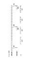
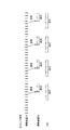
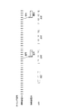
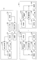
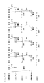
- FIG. 1 is a block diagram of imaging devices 10 and 20 according to a first embodiment of the present disclosure. It is a sequence diagram of the imaging method concerning the embodiment. It is an explanatory view for explaining detection of a subject concerning the embodiment. It is an explanatory view (the 1) for explaining an example of the timing signal concerning the embodiment. It is an explanatory view (the 2) for explaining an example of the timing signal concerning the embodiment. It is an explanatory view (the 3) for explaining an example of the timing signal concerning the embodiment. It is an explanatory view (the 4) for explaining an example of the timing signal concerning the embodiment. It is an explanatory view for explaining an example of a photography scene in the embodiment.
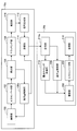
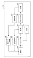
- imaging device 10, 20 concerning modification 1 of the embodiment It is an explanatory view for explaining an example of a timing signal concerning modification 1 of the embodiment. It is a block diagram of imaging device 10a, 20a concerning the modification 2 of the embodiment. It is a block diagram of imaging device 10b concerning a 2nd embodiment of this indication. It is an explanatory view for explaining an arrangement example of a solid-state image sensor array 300 of the imaging unit 100b according to the embodiment. It is a block diagram of imaging device 10b, 20 concerning the modification 3 of the embodiment. It is an explanatory view (the 1) explaining an example of mounting of an imaging device concerning a 3rd embodiment of this indication. It is an explanatory view (the 2) explaining an example of mounting of an imaging device concerning the embodiment.
- a plurality of components having substantially the same or similar functional configurations may be distinguished by attaching different numerals after the same reference numerals. However, when it is not necessary to distinguish each of a plurality of components having substantially the same or similar functional configuration, only the same reference numeral is given. Also, similar components in different embodiments may be distinguished by attaching different alphabets after the same reference numerals. However, when it is not necessary to distinguish each of similar components in particular, only the same reference numeral is attached.
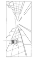
- a self-luminous traffic sign 1 using an LED as shown in FIG. 1 which is an explanatory view for explaining the background of the present disclosure can be mentioned.
- Such a self-luminous traffic sign 1 can display, for example, a number corresponding to the regulation speed by the light emission of the LED, and therefore, the driver can easily carry out the regulation speed even in a situation where visibility is poor such as night It becomes possible to visually recognize.
- the LED of the self-luminous traffic sign 1 is not felt by humans due to the frequency of the AC power supply that supplies power to the LED, the frequency of the power supply controlled by the control device that adjusts the brightness of the LED, etc.
- periodic flicker flicker phenomenon
- the period of the flicker phenomenon of the LED depends on the frequency of the supplied AC power and the frequency set by the contractor who installs the traffic sign or the administrator considering the visibility. Therefore, in a large number of self-luminous traffic signs 1 installed on roads and the like throughout the country, the period of the flicker phenomenon of the LED is not constant.
- the self-luminous traffic sign 1 is imaged by the on-vehicle imaging device
- the self-luminous traffic sign 1 is imaged at the moment when the LED is turned off due to the flicker phenomenon, so from the captured image self-luminous traffic
- the label content for example, the regulation rate
- the LED of the self-luminous traffic sign 1 generally has a flicker frequency of 100 to 250 Hz.
- Patent Document 1 discloses an example of an imaging apparatus for imaging an object (traffic light) having a flicker phenomenon.
- the imaging device of Patent Document 1 determines whether the traffic light is in the intended blinking state or in the blinking state by the flicker phenomenon by measuring the blinking period of the traffic light and comparing the measured period with the threshold value. And selecting a captured image to be stored based on the determination result. That is, Patent Document 1 only determines the blinking state of the traffic light and only selects a representative image indicating the state of the traffic light according to the blinking state, and the details of the object (for example, the object is displayed) It is not a technology to acquire an appropriate captured image that can recognize details of the content).
- a method of imaging an object at the time of lighting of the object can be considered by lengthening the exposure time of the imaging device to an integral multiple of the cycle of the flicker phenomenon.
- a captured image may be saturated (also referred to as "overexposure") due to the long exposure time.
- motion blur may occur in the captured image (also referred to as “subject blur”).
- it is difficult to recognize details of the object for example, details of the content displayed by the object
- the image of the captured object is unclear. That is, in such a case, for example, it is difficult to recognize the contents of the sign, and it is difficult to establish safe and secure driving by recognition based on the captured image.
- the present inventor can implement an embodiment of the present disclosure that can obtain an appropriate captured image that can recognize an object even when a flicker phenomenon occurs.
- the self-luminous traffic sign 1 having a flicker phenomenon for example, imaging capable of recognizing the sign content indicated by the self-luminous traffic sign 1 You can get an image.
- safe and safe driving of the vehicle can be established by using the recognized sign contents.
- an embodiment of the present disclosure is applied to an imaging apparatus for acquiring a captured image of an object to be displayed by emission of light such as an LED
- the embodiment of the present disclosure is an example.
- the present invention is not limited to the application to the imaging apparatus as described above.
- an embodiment of the present disclosure may be applied to an imaging device used for imaging under an illumination device (irradiator) such as a fluorescent lamp (flicker frequency is 100 Hz or 120 Hz).
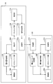
- FIG. 2 is a block diagram of the imaging devices 10 and 20 according to the present embodiment.
- the imaging device 10 includes an imaging unit (first imaging unit) 100, an A / D converter unit 102, a detection unit 104, an exposure amount control unit 106, a tracking unit 108, and estimation.
- a unit 110, a signal generation unit 112, and a transmission unit 114 are mainly included.
- details of each functional unit of the imaging device 10 will be described.
- the imaging unit 100 has a function of imaging an object. Also in the imaging device 20 described later, the imaging unit 200 similar to the imaging unit 100 is provided. However, the imaging frame rate of the imaging unit 200 (a frame rate higher than the second frame rate) The imaging can be performed at a first frame rate (e.g., 1000 fps) More specifically, the imaging unit 100 can perform imaging at an imaging frame rate of about 100 to 10000 fps.
- the imaging frame rate refers to the number of imaging frames (still images) per unit time (one second), and is indicated in units of fps (frames per second).
- Optical system mechanism including an imaging lens, an aperture mechanism, a zoom lens, a focus lens Mainly having a solid-state image sensor array 300 to generate an imaging signal (see FIG. 14), and a drive system mechanism for controlling the optical system mechanism (not shown) by photoelectrically converting the imaging light obtained in the optical system mechanism.
- the optical system mechanism condenses incident light from an object (subject) as an optical image on the solid-state imaging element array 300 using the lens.
- the solid-state imaging element array 300 is realized by, for example, a charge coupled device (CCD) sensor array, a complementary metal oxide semiconductor (CMOS) sensor array, or the like.
- CMOS complementary metal oxide semiconductor
- the solid-state imaging element array 300 photoelectrically converts the formed optical image in units of pixels, reads the signal of each pixel as an imaging signal, and outputs the signal to an A / D converter unit 102 described later.
- the pixel arrangement in the solid-state imaging device array 300 is not particularly limited, and, for example, a Bayer arrangement, a BW arrangement (Mono arrangement) in which all of them are clear pixels, or the like can be selected.
- the drive system mechanism has a stepping motor or the like for driving a lens or the like.
- the A / D converter unit 102 converts an imaging signal from the solid-state imaging device array 300 of the imaging unit 100 from an analog signal to a digital signal, and outputs the digital signal to a detection unit 104 described later.
- the A / D converter unit 102 is realized by, for example, an electronic circuit.
- the detection unit 104 performs predetermined image processing on the digital signal output from the A / D converter unit 102, and detects an object based on the acquired captured image.
- the detection unit 104 is mainly configured with hardware such as a central processing unit (CPU), a read only memory (ROM), and a random access memory (RAM) provided in the imaging device 10. The details of detection of an object in the detection unit 104 will be described later.
- the exposure amount control unit 106 detects the brightness of the entire captured image or an object in the captured image, and controls the imaging unit 100 described above so that the brightness of the captured image becomes appropriate based on the detection result. .
- the exposure amount control unit 106 can detect the luminance by detecting the amount of light received by the solid-state imaging device array 300 of the imaging unit 100.
- the luminance used to control the imaging unit 100 an integral value, an average value, a maximum value, a minimum value, or the like of the luminance of each pixel of the entire captured image can be used.
- the exposure amount control unit 106 is mainly configured with hardware such as a CPU, a ROM, and a RAM provided in the imaging device 10.
- the tracking unit 108 tracks the target detected by the detection unit 104 described above in a plurality of imaging frames (still images) continuously imaged at high speed by the imaging unit 100.
- the tracking unit 108 mainly includes hardware such as a CPU, a ROM, and a RAM provided in the imaging device 10. The details of tracking of an object in the tracking unit 108 will be described later.
- the estimation unit 110 estimates period information of the flicker phenomenon of the object based on the plurality of imaging frames of the tracked object.
- the estimation unit 110 is mainly configured with hardware such as a CPU, a ROM, and a RAM provided in the imaging device 10. The details of the estimation in the estimation unit 110 will be described later.
- the signal generation unit 112 generates a timing signal for imaging an object in the imaging device 20 described later, based on the estimation result of the estimation unit 110 described above. In other words, the signal generation unit 112 generates a synchronization signal for the imaging device 20.
- the said timing signal is output to the imaging device 20, and becomes a reference
- the signal generation unit 112 is mainly configured with hardware such as a CPU, a ROM, and a RAM provided in the imaging device 10. The details of the generation of the timing signal in the signal generation unit 112 will be described later.
- the transmission unit 114 is a communication module for transmitting a timing signal or the like to the imaging device 20.
- the transmission unit 114 establishes synchronization by transmitting a pulse signal to a reception unit 214 of the imaging device 20 described later.
- the transmission unit 114 synchronizes the time with the reception unit 214 of the imaging device 20 described later using a technology such as Ethernet AVB (IEEE 802.1 Audio / Video Bridging) or the like to synchronize timing. Transmission and reception may be established.
- the time synchronization in the imaging devices 10 and 20 is accurately established by the technology of IEEE802.1AS, which is one of the components of the Ethernet AVB, and the timing signal is transmitted from the imaging device 10 to the imaging device 20 via packets. It can be output.
- the imaging device 10 may have a positioning unit (not shown) for positioning the position of the imaging device 10 in addition to the above, or the above-mentioned positioning unit provided separately from the imaging device 10 You may use sensing data.
- the positioning unit is realized by, for example, a GPS (Global Positioning System) positioning unit, receives a radio wave from a GPS satellite, and detects a position where the imaging device 10 is present.
- the positioning unit may transmit and receive to and from, for example, Wi-Fi (Wireless Fidelity (registered trademark), Bluetooth (registered trademark), mobile phone, PHS (Personal Handy-phone System), smartphone, etc. other than GPS. It may be a device that detects the position by distance communication or the like.
- the imaging device 10 includes a storage unit (not illustrated) that stores a captured image captured by the imaging device 10 and programs and parameters for the imaging device 10 to execute each function. You may
- the storage unit 122 is configured by, for example, a RAM.
- the imaging device 10 has an operation display unit (not shown) for displaying a captured image captured by the imaging device 10 to the user and further receiving an input operation of the user. May be
- the display function of the operation display unit is realized by, for example, a liquid crystal display (LCD) device or an organic light emitting diode (OLED) device.
- the operation receiving function of the operation display unit is realized by, for example, a touch panel.
- the imaging device 20 includes an imaging unit (second imaging unit) 200, an A / D converter unit 202, an exposure amount control unit 206, a receiving unit 214, a processing unit 216, and An exposure timing control unit 218 is mainly included.
- the details of each functional unit of the imaging device 20 will be described below.
- the imaging unit 200, the A / D converter unit 202, and the exposure amount control unit 206 are common to the imaging unit 100, the A / D converter unit 102, and the exposure amount control unit 106 of the imaging device 10. Therefore, the explanation is omitted here.
- the receiving unit 214 is a communication module for receiving a timing signal or the like from the imaging device 10. As described above, the receiver 214 establishes synchronization, for example, by transmitting a pulse signal with the transmitter 114. Alternatively, the reception unit 214 establishes transmission and reception of timing signals by synchronizing time with the transmission unit 114 using a technology such as Ethernet AVB (IEEE 802.1 Audio / Video Bridging). It is also good.
- Ethernet AVB IEEE 802.1 Audio / Video Bridging
- the processing unit 216 performs various signal processing such as white balance adjustment, color correction, edge enhancement, and gamma correction on the imaging signal from the A / D converter unit 202, and acquires a captured image.
- the image of the self-luminous traffic sign 1 is extracted from the captured image acquired by the processing unit 216, and the content of the self-luminous traffic sign 1 can be recognized by analyzing the extracted image.
- the processing unit 216 is mainly configured with hardware such as a CPU, a ROM, and a RAM provided in the imaging device 20.
- the exposure timing control unit 218 controls imaging timing of the imaging unit 200 based on the timing signal from the imaging device 10. For example, the exposure timing control unit 218 detects a shift between the exposure start timing for acquiring the current imaging frame and the timing signal, and adjusts the start timing to the timing signal based on the detection result.
- the imaging unit 200 is controlled.
- the exposure timing control unit 218 is mainly configured with hardware such as a CPU, a ROM, and a RAM provided in the imaging device 20.
- each solid-state imaging element array 300 included in the imaging unit 100 and the imaging unit 200 can be a Bayer arrangement or a BW arrangement.
- the imaging device 20 stores a captured image captured by the imaging device 10, a program and parameters for the imaging device 10 to execute each function (shown in FIG. May be omitted.
- FIG. 3 is a sequence diagram of the imaging method according to the present embodiment.
- the imaging method according to the present embodiment includes a plurality of steps from step S100 to step S700.
- the outline of each step included in the imaging method according to the present embodiment will be described below.
- only the outline of the imaging method according to the present embodiment will be described, and the details of each step will be described later.
- the imaging device 10 continuously images an object (for example, the self-emission traffic sign 1 or the like) at a high frame rate (for example, 1000 fps) and detects the object from a plurality of acquired imaging frames.
- the frame rate (high-speed frame rate) (first frame rate) of the imaging device 10 is equal to or greater than a value obtained by multiplying the period of the flicker light source by twice the reciprocal of the duty ratio. By doing this, it is possible to accurately capture an object for each imaging frame. For example, when the pulse width is 1 ms and the pulse period is 4 ms in the flicker phenomenon, the duty ratio of the flicker phenomenon is 0.25.
- the high speed frame rate is preferably set to 2000 fps or more obtained by multiplying 4 which is the reciprocal of 0.25 of the duty ratio by 2 and further multiplying 250 Hz of the flicker frequency. Further, details of detection of an object will be described later.
- Step S200 The imaging device 10 performs tracking on a detected object in a plurality of imaging frames continuously acquired at a high frame rate. In addition, the detail of tracking of a target object is mentioned later.
- Step S300 The imaging device 10 estimates periodic information (frequency, lighting time, lighting interval, and the like) of the flicker phenomenon of the object based on the imaging frame of the object being tracked. Specifically, the imaging device 10 estimates the period information based on the change in the luminance of the object on the plurality of imaging frames. In addition, the detail of estimation of period information is mentioned later.
- Step S400 The imaging device 10 generates a timing signal that determines the imaging timing of the object based on the estimated period information.
- Step S500 The imaging device 10 transmits a timing signal to the imaging device 20.
- Step S600 The imaging device 20 receives a timing signal from the imaging device 10.
- Step S600 The imaging device 20 controls imaging timing in the imaging unit 200 based on the received timing signal. Furthermore, the imaging device 20 can obtain a captured image of the object by processing the imaging signal obtained by the imaging unit 200. At this time, the imaging device 20 performs imaging at a low speed, low frame rate (second frame rate) (for example, 30 fps, 60 fps) as compared to the imaging device 10.
- second frame rate for example, 30 fps, 60 fps
- the change in the brightness of the object in a plurality of imaging frames is detected by tracking the object, and the period of the flicker phenomenon (flickering) of the object is detected by the change in the detected brightness.
- Estimate the information since the object is tracked, it is possible to accurately capture the change in the luminance of the object, and furthermore, it is possible to accurately estimate the period information.
- a timing signal for appropriately imaging an object is generated based on the estimated period information.
- the imaging device 20 captures an object based on the timing signal, it is possible to acquire an optimal captured image that can more reliably recognize the object. .
- the cycle information is rapidly estimated using the imaging frame obtained at the high frame rate and the timing signal is generated, the imaging device 20 images the object in real time. be able to. Next, details of each step in such an imaging method will be described.
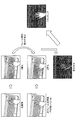
- FIG. 4 is an explanatory view for explaining detection of an object according to the present embodiment.
- the example shown in FIG. 4 shows a method of detecting an object to be tracked from a plurality of imaging frames imaged at a high frame rate.
- the object is not the self-emitting traffic sign 1 but a human hand.
- the hand moves minutely in a narrow area for typing on the keyboard.
- the object is not limited to such a human hand, and may be, for example, a self-luminous traffic sign 1 that appears to move from a car window. It is not particularly limited.
- a gray-scaled imaging frame is generated by processing the imaged color imaging frame as shown on the left side of FIG. 4 under a predetermined condition.
- the red (R) pixel value (color information) of each pixel in the color imaging frame is extracted Do.
- a pixel having a high R pixel value is white, and a pixel having a low R pixel value is black.
- the R pixel value of each pixel of the grayscaled imaging frame is compared with a predetermined threshold, and for example, the pixel value of a pixel equal to or larger than the predetermined threshold is converted to 1 and the predetermined threshold Convert pixel values of less than 0 pixels to 0.
- any element value of red, green, or blue (RGB) may be extracted, or an average value of three element values may be used.
- RGB red, green, or blue
- a value obtained by integrating each element value may be used.
- the person in the case of detecting a person as an object, the person can be detected based on the skin color of the person. Specifically, pixels corresponding to human skin color are extracted by extracting only pixels in which element values of three colors satisfy the following relational expression (1). Then, it is possible to detect a person based on the skin color extraction result.
- R, G and B indicate element values of each color.
- ⁇ MAX and ⁇ MIN indicate the maximum value and the minimum value among the element values of each color.
- ⁇ , ⁇ , ⁇ MAX, ⁇ MIN are coefficients that can be set arbitrarily by the user.
- three element values of each pixel in a color imaging frame are processed by a predetermined formula, index values at each pixel are calculated, and pixels having the calculated index value within a predetermined range You may do by extracting only.
- three element values of each pixel may be converted into index values by an HSV model represented by hue, saturation, and lightness.
- the lower middle row of FIG. 4 is obtained. As shown, we extract specific regions (targets) by motion.
- the detection of the object is not limited to the method described above.
- the feature points of the object are stored in advance, and the feature points stored in the imaging frame are extracted.
- the object may be detected.
- the person is detected based on the feature points (eyes, nose, and mouth) of the face of the person.
- the imaging device 10 When the imaging device 10 is provided with a positioning unit (not shown) for detecting the position of the imaging device 10, the detection of the object may be performed based on the sensing data of the positioning unit.
- the imaging device 10 when the imaging device 10 is mounted on a vehicle and the object is a traffic light, the captured image of the traffic light is an area (for example, a vehicle) fixed to the imaging device 10 (vehicle) It is clear that it appears in the left front area of That is, the traffic light is present in an area fixed with respect to the angle of view of the imaging device 10. Therefore, the imaging device 10 can recognize in advance the position where the traffic light appears by referring to the map information including the position information of the traffic light stored in advance and the sensing data of the positioning unit. Based on this, it is possible to detect a traffic light.
- the detection of the object is not limited to the above-described method, and for example, the imaging frame captured first is displayed to the user, and the user selects a desired object in the imaging frame.
- the object may be detected by selection.
- Step S200 ⁇ 2.4 Object Tracking (Step S200)> Next, tracking of an object in step S200 described above will be described. In the present step S200, as shown on the right side of FIG. 4, tracking (tracking) is performed on the object (the hand in FIG. 4) detected in the above-described step S100.
- the self window method is used to keep track of an object in a plurality of consecutive imaging frames imaged at a high frame rate.
- self-windowing is a type of algorithm that tracks objects in imaging frames imaged at high frame rates.
- the moving distance (difference) of the object in a plurality of imaging frames is small. Therefore, when an extraction window for extracting the object is set in an area around the object in the previous imaging frame, the object is included in the extraction window also in the next imaging frame. It becomes. More specifically, the extraction window is set as a pixel area expanded outward by one pixel with respect to the pixel area indicating the object in the previous imaging frame. If the object is not included in the set extraction window at the next imaging frame rate, the object can be included in the extraction window by further increasing the frame rate.
- the extraction window has been described as being set as a pixel region inflated outward by one pixel with respect to the pixel region indicating the target in the previous imaging frame, but in the present embodiment, 1 It is not limited to expanding by a pixel.
- a pixel area inflated by two or more pixels may be set as the extraction window.
- the number of pixels to be expanded can be appropriately selected according to, for example, the frame rate, the speed of the object, and the like.
- the frame rate is further increased when the object is not included in the set extraction window at the next imaging frame rate, but in the present embodiment such a method is used. It is not limited.
- the target object may be included in the extraction window by adjusting the number of pixels that expand when setting the extraction window.
- the self-window method generates a target extraction image by calculating the logical product between the extraction window calculated from the previous imaging frame and the image of the next binarized object, Track objects. Further, according to the self-window method, by comparing the image of the object with the target extraction image of the imaging frames before and after, not only the position information and area (shape) information of the object but also the object Information such as the moving direction and moving speed can also be acquired. As apparent from the above description, in the case of using the self-window method, it is preferable that an imaging frame used when tracking an object is imaged at a high frame rate.
- the tracking of the object is not limited to the above-described example, and another method may be used.
- the tracking of the object may be performed based on the feature points common to the front and back imaging frames.
- Step S300 estimation of period information in the above-described step S300 will be described.
- the average value of the luminance of the image of the tracked object is stored for each of a plurality of imaging frames, and discrete Fourier transform (DFT) is used on the stored data.
- DFT discrete Fourier transform
- the cycle information of the flicker phenomenon such as the frequency, the width of the lighting time, and the lighting interval is estimated.
- the brightness of the object in the plurality of imaging frames is It should change according to the cycle of the flicker phenomenon. Therefore, in the present embodiment, the average value of the luminances of a plurality of pixels corresponding to the image of the object is acquired for each of a plurality of imaging frames acquired at a predetermined frame rate, and DFT is applied. A time change, that is, a frequency component (frequency, width of lighting time, lighting interval, etc.) in time change of luminance is estimated. In addition, since the imaging frame used when estimating period information is acquired at a frame rate faster than the period of the flicker phenomenon, the period information of the flicker phenomenon is estimated by applying DFT. It is possible.
- estimation of period information is not limited to the above-mentioned example, You may use another method.
- a plurality of imaging frames in a predetermined period are analyzed, and the number of imaging frames in which the object is on and the number of imaging frames in which the object is off are counted.
- the period information may be estimated.
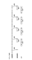
- Step S400 generation of the timing signal in the above-described step S400 will be described with reference to FIGS. 5 to 8 are explanatory diagrams for explaining an example of the timing signal according to the present embodiment.
- the timing of imaging in the imaging device 10 is indicated by vertical lines in the upper part.
- the timing signal transmitted from the imaging device 10 to the imaging device 20 is indicated by a vertical line, and the exposure time in the imaging device 20 is indicated by a band extending in the horizontal direction.
- the lighting time of LED which is a target object is shown by the strip extended laterally.
- the signal generation unit 112 generates a signal for controlling the exposure start timing in the imaging device 20 or a timing signal for controlling the exposure end timing based on the period information estimated in step S300 described above. Generate Whichever signal is generated, the generated timing signal satisfies the following conditions. Specifically, in the present embodiment, the frequency of the timing signal is set such that the imaging frame rate (high speed frame rate) of the imaging device 10 is an integral multiple of the imaging frame rate (low speed frame rate) of the imaging device 20. It is set. Furthermore, the frequency of the timing signal is set such that the frequency of the flicker phenomenon (the frequency of the blinking of the LED) becomes an integral multiple of the imaging frame rate of the imaging device 20.
- FIG. 5 shows a case where a timing signal for controlling the timing of the exposure end in the imaging device 20 is generated, and further, the frequency of the flicker phenomenon (the frequency of blinking of the LED) and the frame rate of the imaging device 20 It shows the case of being identical. That is, in the example shown in FIG. 5, the imaging device 20 is controlled to end the exposure upon receiving the timing signal.
- the imaging frame rate of the imaging device 10 is 1200 fps
- the imaging frame rate of the imaging device 20 is 120 fps
- the blinking frequency of the LED is 120 Hz.
- FIG. 6 shows a case where a timing signal for controlling the timing of the exposure end in the imaging device 20 is generated, and the frequency of the flicker phenomenon (the frequency at which the LED blinks) is double the imaging frame rate of the imaging device 20. Indicates the case.
- the imaging frame rate of the imaging device 10 is 1200 fps
- the imaging frame rate of the imaging device 20 is 60 fps
- the blinking frequency of the LED is 120 Hz.
- FIG. 7 shows the case where a timing signal for controlling the timing of the exposure start in the imaging device 20 is generated, and the frequency of the flicker phenomenon (the frequency at which the LED blinks) and the frame rate of the imaging device 20 are the same.
- the imaging device 20 is controlled to start exposure upon receiving the timing signal.
- the imaging frame rate of the imaging device 10 is 1200 fps
- the imaging frame rate of the imaging device 20 is 120 fps
- the blinking frequency of the LED is 120 Hz.
- FIG. 8 shows a case where a timing signal for controlling the exposure start timing in the imaging device 20 is generated, and the frequency of the flicker phenomenon (the frequency at which the LED blinks) is double the imaging frame rate of the imaging device 20. Indicates the case.
- the imaging frame rate of the imaging device 10 is 1200 fps
- the imaging frame rate of the imaging device 20 is 60 fps
- the blinking frequency of the LED is 120 Hz.
- the frequency of the timing signal is set to a value obtained by multiplying the period of the flicker light source and the reciprocal of the duty ratio.
- the generated timing signals are not limited to the signals as shown in FIGS. 5 to 8.
- the timing signal is not particularly limited as long as it can control the imaging device 20 so that the exposure period of the imaging device 20 can overlap at least a part of the lighting period of the LED.
- the period of the flicker phenomenon (the frequency at which the LED blinks) and the imaging frame rate of the imaging device 20 may not be in an integral multiple relationship due to a slight error. In that case, as time passes, the cycle is shifted, and it may not be possible to capture an object to be lit by the imaging device 20. Therefore, in the present embodiment, periodic information of the flicker phenomenon is estimated once in several times, preferably every time, and the above-described periodic deviation is avoided by generating a timing signal based on the estimation result. it can.
- the imaging unit 200 of the imaging device 20 is preferably a global shutter, that is, simultaneous exposure batch readout, but may be a rolling shutter, that is, line exposure sequential readout.
- the global shutter refers to control such that each pixel 302 (see FIG. 14) of the solid-state image sensor array 300 of the imaging unit 200 is simultaneously exposed and simultaneously read out.
- the rolling shutter refers to control such that each pixel 302 of the solid-state imaging device array 300 of the imaging unit 200 is sequentially exposed line by line and read out.
- an object to be lit is imaged by generating a timing signal in consideration of a shift in exposure time / readout time for each line. Can.
- the imaging unit 200 in consideration of the above-described deviation, it is possible to capture an object to be lit.
- changes in the brightness of the object in a plurality of imaging frames are detected by tracking the object, and the flicker phenomenon (flickering) of the object occurs due to the detected change in brightness.
- Estimate period information since the object is tracked, it is possible to accurately capture the change in the luminance of the object, and furthermore, it is possible to accurately estimate the period information. Then, in the present embodiment, by generating a timing signal for appropriately imaging the object based on the estimated period information, an optimal imaged image capable of more reliably recognizing the object is acquired. can do. Further, in the present embodiment, since the cycle information is rapidly estimated using the imaging frame obtained at the high frame rate and the timing signal is generated, the imaging device 20 images the object in real time.
- the imaging devices 10 and 20 according to the present embodiment are mounted on a vehicle and the self-luminous traffic sign 1 is imaged, the imaging device 20 is a self-luminous traffic sign in a lit state. Since 1 can be imaged, the sign content (speed limit) of the self-luminous traffic sign 1 can be reliably recognized. As a result, according to the present embodiment, it is possible to construct a safe driving support system for supporting a driver's driving using a captured image, and also automatic driving.
- this embodiment is not limited to imaging the above-mentioned self-luminous traffic sign 1 by the imaging device 20 mounted in the vehicle, and a lighting device etc. which exist around the vehicle which is traveling etc. It is also possible to image buildings and illuminations that have In addition, as described later, the present embodiment can also be applied when imaging a plurality of objects having different blinking cycles, and in this case, imaging a plurality of objects in the blinking state simultaneously or Alternatively, some objects may be excluded and imaged.
- the present invention can also be applied to imaging under a fluorescent lamp.
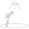
- FIG. 9 which is an explanatory view for explaining an example of the imaging scene in the present embodiment
- the athlete 90 is imaged under the lighting device 80 which blinks due to the flicker phenomenon indoors in the gymnasium 3 or the like.
- the present invention can also be applied to an imaging device. Specifically, according to the present embodiment, even if the athlete 90 being illuminated by the lighting device 80 having a flicker phenomenon such as a fluorescent light is performing a sport that moves quickly like a basketball, The movement of the athlete 90 can be imaged.
- FIG. 10 is a block diagram of imaging devices 10 and 20 according to the first modification of the present embodiment.
- FIG. 11 is an explanatory diagram for describing an example of a timing signal according to the first modification of the present embodiment. In FIG. 11, the timing of imaging in the imaging device 10 is indicated by vertical lines in the upper part.
- the timing signals transmitted from the imaging device 10 to the imaging device 20-1 and the imaging device 20-n are indicated by vertical lines, and by the band extending in the horizontal direction The exposure time in the imaging devices 20-1 and 20-n is shown.
- the lighting time of the LED (1) which is the target of the imaging device 20-1 and the lighting time of the LED (n) which is the target of the imaging device 20-n And by a laterally extending band.
- a plurality (n) of the above-described imaging devices 20 are provided. Further, in the present modification, the detection unit 104, the tracking unit 108, and the estimation unit 110 of the imaging device 10 detect and track a plurality of objects, and estimate the cycle information of the flicker phenomenon of each object. Furthermore, the signal generation unit 112 of the imaging device 10 generates a plurality of timing signals for imaging each object based on the estimated period information. Then, the plurality of timing signals generated by the imaging device 10 are transmitted to each of the plurality of imaging devices 20, and each imaging device 20 images a corresponding target. Therefore, for example, when the cycle information of the flicker phenomenon of each object is different from each other, the imaging device 10 generates a plurality of timing signals of different cycles.
- the imaging device 10 transmits timing signals of different cycles to the imaging device 20-1 and the imaging device 20-n.
- the imaging device 10 generates a timing signal for controlling the timing of the exposure end in the imaging devices 20-1 and 20-n.
- the imaging devices 20-1 and 20-n are exposed according to each blinking period. Thus, it is possible to capture the lighted LED (1) and the LED (n).
- FIG. 11 shows that the imaging device 10 transmits timing signals of different cycles to the imaging device 20-1 and the imaging device 20-n.
- the imaging device 10 generates a timing signal for controlling the timing of the exposure end in the imaging devices 20-1 and 20-n.
- the imaging frame rate of the imaging device 10 is 1200 fps
- the imaging frame rates of the imaging device 20-1 and the imaging device 20-n are 100 fps
- the imaging devices 20-1 and 20 -N will perform exposure at different timings.
- the frequency of blink is 100 Hz, for example, LED (1) and LED (n) light at different timing.
- the imaging device 20 can be estimated based on the estimated period information. However, it can also be controlled to image only a specific object.
- the case where one of the two installed illuminations is to be imaged by the imaging device 20 is considered. In this case, it is assumed that the blinks of these illuminations are not synchronized with each other.
- the imaging device 10 estimates cycle information of blinks of two illuminations, calculates a period for imaging only one illumination, and the imaging device 20 based on the calculation result. Control.
- the imaging device 10 transmits timing signals to simultaneously expose the two imaging devices 20 to both of them.
- the control timing of the millimeter wave radar 50 (see FIG. 16) provided in the vehicle may be synchronized with the timing at which the two imaging devices 20 capture images with high accuracy. By doing this, the recognition accuracy of the object can be further improved.
- the imaging device 10 generates and transmits a timing signal for controlling the exposure timing of the imaging device 20.
- the imaging device 10 may transmit not only the timing signal for controlling the exposure timing of the imaging device 20 but also a signal for controlling the aperture and shutter speed of the imaging unit 200 of the imaging device 20. .
- FIG. 12 is a block diagram of imaging devices 10a and 20a according to a modification of the present embodiment.
- an imaging device 10a according to the present modification will be described with reference to FIG.
- the imaging device 10a according to the present modification is, similarly to the imaging device 10, an imaging unit 100, an A / D converter unit 102, a detection unit 104, an exposure amount control unit 106a, a tracking unit 108, and A unit 110, a signal generation unit 112, and a transmission unit 114 are mainly included.
- the imaging unit 100, the A / D converter unit 102, the detection unit 104, the tracking unit 108, the estimation unit 110, the signal generation unit 112, and the transmission unit 114 are the same as those of the imaging device 10 described above. Only the exposure control unit 106a will be described.
- the exposure amount control unit 106a detects the luminance in the captured image of the object, and based on the detection result, the exposure amount of the imaging unit 100 described above, that is, the diaphragm, so that the luminance of the object in the captured image becomes appropriate. , Shutter time etc. Further, the exposure amount control unit 106 a generates an exposure control signal for controlling the exposure amount of the imaging unit 200 of the imaging device 20 a as the imaging unit 100, and outputs the generated exposure control signal to the transmission unit 114.
- the imaging device 20a according to the present modification like the imaging device 20, includes an imaging unit 200, an A / D converter unit 202, an exposure amount control unit 206, a receiving unit 214a, a processing unit 216, and An exposure timing control unit 218 is mainly included.
- the imaging unit 200, the A / D converter unit 202, the exposure amount control unit 206, the processing unit 216, and the exposure timing control unit 218 are common to the above-described imaging device 20, the description is omitted. Explain only.
- the receiving unit 214a not only outputs the timing signal from the imaging device 10a to the exposure timing control unit 218, but also outputs an exposure control signal from the imaging device 10a to the exposure amount control unit 206.
- Second embodiment >> In the first embodiment described above, it is premised that the imaging devices 10 and 20 and two or more imaging devices perform the first embodiment. However, the present embodiment is not limited to implementation with two or more imaging devices, and may be implemented with one imaging device. Thus, a second embodiment of the present disclosure will be described in which one imaging device 10b is used.
- FIG. 13 is a block diagram of an imaging device 10b according to the present embodiment.
- FIG. 14 is an explanatory diagram for describing an arrangement example of the solid-state imaging element array 300 of the imaging unit 100 b according to the present embodiment.
- R indicates a pixel for detecting red
- G indicates a pixel for detecting green
- B indicates a pixel for detecting blue.
- the imaging device 10 b includes an imaging unit 100 b, an A / D converter unit 102, a detection unit 104, an exposure amount control unit 106, a tracking unit 108, an estimation unit 110, and a signal generation unit 112. , Processing unit 116 and exposure timing control unit 118 mainly.
- the respective functional units are common to the functional units having the same names of the imaging devices 10 and 20 according to the above-described first embodiment, and thus the description of the respective functional units is omitted here.
- a pixel group (pixel group for short-time exposure) (first imaging element group) 302a to be imaged at a high frame rate.
- first imaging element group a pixel group for short-time exposure
- second imaging element group a pixel group for long time exposure
- the pixel 302a that captures an image at a high frame rate like the imaging device 10
- the pixel 302b that captures an image at a low frame rate like the imaging device 20
- the pixel 302 a and the pixel 302 b function as the imaging device 10 and the imaging device 20 according to the above-described first embodiment, respectively, so that one imaging device 10 b can be realized.
- the pixels 302 a for the high frame rate and the pixels 302 b for the low frame rate are alternately provided by two rows is shown.
- the pixel array for RGB is shown, but in the present embodiment, it may be replaced with the BW array.
- the pixels 302 to be replaced with the BW array may be the pixels 302 a for the high frame rate, the pixels 302 b for the low frame rate, or both pixels 302.
- the solid-state imaging device array 300 according to the present embodiment is not limited to the example shown in FIG. 14, and various arrays can be used as long as two types of pixels 302 a and 302 b are included. .
- the pixels 302a for the high-speed frame rate of the solid-state imaging device array 300 in the pixel array as described above function in the same manner as the imaging unit 100 of the imaging device 10 in the first embodiment. That is, the imaging device 10b generates an imaging frame based on the image signal acquired by the pixel 302a for high frame rate, performs detection and tracking of an object, estimates period information of the flicker phenomenon, and generates a timing signal. Do. In addition, the pixels 302b for the low frame rate of the solid-state imaging element array 300 are lit in the same manner as the imaging unit 200 of the imaging device 20 in the first embodiment by performing imaging under the control of the above-described timing signal. An image of an object can be taken.
- the final captured image of the target that is, the captured image of the target by the imaging device 20 in the first embodiment is an image signal acquired by the pixel 302b for the low frame rate. It is generated using.
- the captured image may be generated using image signals of both the pixel 302a for high frame rate and the pixel 302b for low frame rate.
- the obtained captured image of the target object is a captured image of a high dynamic range (HDR) having a wide contrast.
- HDR high dynamic range
- the imaging device 10 b is independent. Also, an object to be lit can be imaged.
- FIG. 15 is a block diagram of imaging devices 10b and 20 according to a modification of the present embodiment.
- the imaging device 10b is configured in the same manner as the imaging device 10b according to the second embodiment. Furthermore, in the present modification, a plurality (n) of imaging devices 20 according to the first embodiment are provided.
- the detection unit 104, the tracking unit 108, the estimation unit 110, and the signal generation unit 112 of the imaging device 10b detect and track each object, estimate period information, and generate a timing signal based on the estimation result. Generate Then, each timing signal generated by the imaging device 10b is transmitted to each of the imaging devices 20 and 20-n.
- final captured images of a plurality of objects are acquired by the imaging device 10b and each of the imaging devices 20-1 to 20-n.
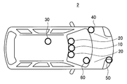
- FIG. 16 and FIG. 17 are explanatory diagrams for explaining a mounting example of the imaging device according to the third embodiment of the present disclosure.
- the imaging device 10 according to the present embodiment is provided at the upper center of the windshield of the passenger car 2, and the two imaging devices 20 according to the present embodiment are provided to sandwich the imaging device 10. .
- the passenger car 2 is provided with a positioning sensor 30, an acceleration sensor 40, a millimeter wave radar 50, an illuminance sensor 60, and the like.
- the acceleration sensor 40 detects an acceleration generated by the movement of the passenger car 2.
- the millimeter wave radar 50 emits a millimeter wave (for example, a radio wave having a wavelength of about 1 to 10 mm) around the vehicle and detects a reflected wave, thereby detecting, for example, the distance of an object around the passenger car 2 and the like.
- the illumination sensor 60 detects the brightness of the outside of the passenger car 2.
- the imaging device 10 detects a tracking target, performs tracking, further estimates cycle information of the flicker phenomenon, generates a timing signal, and transmits the timing signal to the two imaging devices 20.
- the two imaging devices 20 receive the timing signal and image an object based on the received timing signal.
- each timing signal is a signal having a different cycle.
- the timing signal (synchronization signal) is such that the two imaging devices 20 can simultaneously image an object.
- sensing data of the positioning sensor 30, the acceleration sensor 40, the millimeter wave radar 50, the illuminance sensor 60, and the like may be used to control imaging in the imaging device 20.
- the imaging devices 10 and 20 are provided on the upper portion of the windshield of the passenger car 2, but in the present embodiment, it is not limited to being installed at such a position. It may be provided on the rear side or the left and right sides of 2.
- these imaging devices 10 and 20 can function as a monitoring system that images the rear of the passenger car 2 instead of the rearview mirror It can support the driving of the hand.
- the drone 70 refers to a device that can fly in a three-dimensional space, having a self-contained flight function and a self-standing attitude control function, etc., which is a small airplane and a construction operator does not get on it.
- the left side of FIG. 17 illustrates a drone 70 on which four imaging devices 10 b according to the second embodiment are mounted.
- a drone 70 on which four imaging devices 10 according to the first embodiment and eight imaging devices 20 according to the first embodiment are mounted is mounted on the right side of FIG. 17, a drone 70 on which one imaging device 10 according to the first embodiment and eight imaging devices 20 according to the first embodiment are mounted is shown.
- the imaging device 10 b is provided at the center of each side surface of the drone 70, and the imaging device 10 b captures an object located in each direction when viewed from the drone 70 can do.
- the imaging device 10 has a wide-angle imaging unit 100 having an angle of view of nearly 180 degrees, and is provided at the center of each side of the drone 70. Furthermore, each imaging device 10 controls a pair of imaging devices 20 positioned so as to sandwich each imaging device 10. For example, the pair of imaging devices 20 are controlled to be synchronized with each other by the imaging device 10, and can perform distance measurement on an object.
- the imaging device 10 has a wide-angle imaging unit 100 having an angle of view of nearly 360 degrees, and is provided at the upper center of the drone 70. Furthermore, the imaging device 10 controls eight imaging devices 20 positioned so as to surround the imaging device 10.
- the imaging apparatus includes the passenger car 2, the drone 70, and a space movement such as an industrial or household robot that can be remotely operated by the pilot or can move independently.
- Possible devices can be installed as a monitoring device of the surrounding situation.
- the imaging device is not limited to being mounted on such a device, and for example, since high-speed imaging is possible, it is difficult for the human eye to observe changes at high speed. It may be mounted on an analysis device that can analyze an object, such as analyzing a phenomenon that occurs. More specifically, as the above-mentioned analysis device, there can be mentioned a measuring device used for analysis such as drop or impact test of an object, explosion test and the like, motion analysis of a sports player and the like.
- a change in luminance of an object in a plurality of imaging frames is detected by tracking the object, and the flicker phenomenon of the object is detected by the change in the detected luminance.
- Estimate the period information of since the object is tracked, it is possible to accurately capture the change in the luminance of the object, and furthermore, it is possible to accurately estimate the period information.
- a timing signal for imaging an object appropriately based on the presumed period information is generated and an object is imaged based on the timing signal, the object is made more reliable. It is possible to acquire an optimal captured image that can be recognized.
- the cycle information is rapidly estimated using the imaging frame obtained at the high frame rate and the timing signal is generated, the imaging device 20 images the object in real time. be able to.
- each step may be processed in an appropriate order.
- each step may be processed partially in parallel or individually instead of being processed chronologically.
- the processing of each step may not necessarily be performed in accordance with the described method, for example, may be processed in another manner by another functional block.
- a detection unit that detects a blinking target or an object illuminated by a blinking irradiation object;
- a tracking unit that performs tracking on the detected object;
- An estimation unit configured to estimate the blinking cycle information based on a plurality of imaging frames of the tracked object;
- a signal generation unit that generates a timing signal for imaging the object based on the estimation result; Equipped with Imaging device.
- It further comprises first and second imaging units for imaging the object, The first imaging unit captures an image at a first frame rate, The second imaging unit performs imaging at a second frame rate that is slower than the first frame rate.
- the imaging apparatus further comprises an imaging unit configured to image the object, the imaging unit including a plurality of imaging devices, The imaging unit has a first imaging element group imaging at a first frame rate, and a second imaging element group imaging at a second frame rate that is lower than the first frame rate.
- the detection unit detects the object based on a plurality of imaging frames of the object acquired at the first frame rate.
- the imaging device according to (4), wherein the detection unit detects the target based on color information of each pixel of the imaging frame.
- the detection unit detects the target based on position information of the imaging device.
- the imaging device according to any one of the above (1) to (3).
- the tracking unit performs tracking on the object based on a comparison of the imaging frames before and after the plurality of imaging frames of the object acquired at the first frame rate. Or the imaging device according to (3).
- the estimation unit is at least one of the blinking frequency, the lighting time, and the lighting interval based on a change in luminance of the target in a plurality of imaging frames of the target acquired at the first frame rate.
- the imaging device according to (2) or (3) above, which estimates one.
- the imaging device (10) The imaging device according to (2), wherein the signal generation unit generates a signal for controlling the timing of the start of exposure of the second imaging unit or a signal for controlling the timing of the end of exposure.
- the detection unit detects a plurality of the objects.
- the tracking unit performs tracking on each of the objects.
- the estimation unit estimates the blinking cycle information on each of the objects,
- the signal generation unit generates timing signals for imaging each of the objects based on the estimation result.
- a detection unit that detects a blinking target or an object illuminated by a blinking irradiation object; A tracking unit that performs tracking on the detected object; An estimation unit configured to estimate the blinking cycle information based on a plurality of imaging frames of the tracked object; A signal generation unit that generates a timing signal for imaging the object based on the estimation result; An imaging device having the A device capable of spatial movement or analysis of the object.
- Reference Signs List 1 self-luminous traffic sign 2 passenger car 3 gymnasium 10, 10a, 10b, 10c, 20, 20a, 20-1 to 20-n imaging device 30 positioning sensor 40 acceleration sensor 50 millimeter wave radar 60 illuminance sensor 70 drone 80 lighting device 90 Athlete 100, 100b, 200 Imaging unit 102, 202 A / D converter unit 104 Detection unit 106, 106a, 206 Exposure amount control unit 108 Tracking unit 110 Estimation unit 112 Signal generation unit 114 Transmission unit 116, 216 Processing unit 118, 218 Exposure timing control unit 214, 214a Receiver 300 Solid-state image sensor array 302, 302a, 302b Pixel
Landscapes
- Engineering & Computer Science (AREA)
- Multimedia (AREA)
- Signal Processing (AREA)
- Physics & Mathematics (AREA)
- General Physics & Mathematics (AREA)
- Theoretical Computer Science (AREA)
- Computer Vision & Pattern Recognition (AREA)
- Mechanical Engineering (AREA)
- Human Computer Interaction (AREA)
- Studio Devices (AREA)
- Transforming Light Signals Into Electric Signals (AREA)
- Traffic Control Systems (AREA)
Abstract
【課題】フリッカ現象が生じている場合であっても、対象物を認知することができるような適切な撮像画像を得ることが可能な撮像装置及び機器を提供する。 【解決手段】点滅する対象物又は点滅する照射体に照らされた対象物を検出する検出部と、検出された前記対象物に対してトラッキングを行うトラッキング部と、トラッキングされた前記対象物の複数の撮像フレームに基づいて、前記点滅の周期情報を推定する推定部と、推定結果に基づいて、前記対象物の撮像のためのタイミング信号を生成する信号生成部と、を備える、撮像装置を提供する。
Description
本開示は、撮像装置及び機器に関する。
近年、安心、安全な自動車を実現させるべく、運転手の運転を支援する安全運転支援システムや自動運転の開発が進められている。このような開発においては、車載の撮像装置等により、車両の周囲に存在する交通標識、車両、通行人等の様々な対象物を認知することが求められている。例えば、認知する対象物の1つとして、LED(light Emitting Diode)を用いた自発光式交通標識を挙げることができる。
ところで、LEDは、LEDに電力を供給する交流電源の周波数等により、人間には感じられない程度ではあるが、周期的なちらつきが存在する。このようなちらつきはフリッカ現象と呼ばれている。このようなフリッカ現象を持つ対象物を撮像する撮像装置の一例が、下記特許文献1に開示されている。
また、上記フリッカ現象に起因して、車載の撮像装置により自発光式交通標識を撮像した際には、LEDが消灯した瞬間に上記自発光式交通標識を撮像し、得られた撮像画像からは自発光式交通標識のLEDによって示される標識の内容が認知できない場合がある。そこで、上述の現象に対する対策として、撮像装置の露光時間をLEDのフリッカ現象の周期の整数倍にまで長くすることにより、LEDの点灯時に確実にLEDを撮像しようとする方法が考えられる。
しかしながら、車載の撮像装置において、露光時間をLEDのフリッカ現象の周期の整数倍にまで長くした場合、撮像画像にモーションブラーが生じたり(「被写体ぶれ」とも呼ぶ)、飽和したり(「白とび」とも呼ぶ)することから、標識内容が認識できるような適切な撮像画像を得ることができないことがある。
そこで、上記事情を鑑みて、本開示では、フリッカ現象が生じている場合であっても、対象物を認知することができるような適切な撮像画像を得ることが可能な、新規且つ改良された撮像装置及び機器を提案する。
本開示によれば、点滅する対象物又は点滅する照射体に照らされた対象物を検出する検出部と、検出された前記対象物に対してトラッキングを行うトラッキング部と、トラッキングされた前記対象物の複数の撮像フレームに基づいて、前記点滅の周期情報を推定する推定部と、推定結果に基づいて、前記対象物の撮像のためのタイミング信号を生成する信号生成部と、を備える、撮像装置が提供される。
さらに、本開示によれば、点滅する対象物又は点滅する照射体に照らされた対象物を検出する検出部と、検出された前記対象物に対してトラッキングを行うトラッキング部と、トラッキングされた前記対象物の複数の撮像フレームに基づいて、前記点滅の周期情報を推定する推定部と、推定結果に基づいて、前記対象物の撮像のためのタイミング信号を生成する信号生成部と、を有する撮像装置が搭載された、空間移動可能な、又は、前記対象物の解析可能な機器が提供される。
以上説明したように本開示によれば、フリッカ現象が生じている場合であっても、対象物を認知することができるような適切な撮像画像を得ることが可能な、撮像装置及び機器を提供することができる。
なお、上記の効果は必ずしも限定的なものではなく、上記の効果とともに、または上記の効果に代えて、本明細書に示されたいずれかの効果、または本明細書から把握され得る他の効果が奏されてもよい。
以下に添付図面を参照しながら、本開示の好適な実施の形態について詳細に説明する。なお、本明細書及び図面において、実質的に同一の機能構成を有する構成要素については、同一の符号を付することにより重複説明を省略する。
また、本明細書および図面において、実質的に同一または類似の機能構成を有する複数の構成要素を、同一の符号の後に異なる数字を付して区別する場合がある。ただし、実質的に同一または類似の機能構成を有する複数の構成要素の各々を特に区別する必要がない場合、同一符号のみを付する。また、異なる実施形態の類似する構成要素については、同一の符号の後に異なるアルファベットを付して区別する場合がある。ただし、類似する構成要素の各々を特に区別する必要がない場合、同一符号のみを付する。
なお、説明は以下の順序で行うものとする。
1.本発明者が本開示に係る実施形態を創作するに至る背景
2.第1の実施形態
2.1 撮像装置の構成
2.2 撮像方法の概略
2.3 対象物の検出(ステップS100)
2.4 対象物のトラッキング(ステップS200)
2.5 周期情報の推定(ステップS300)
2.6 タイミング信号の生成(ステップS400)
2.7 変形例1
2.8 変形例2
3.第2の実施形態
3.1 撮像装置の構成
3.2 変形例3
4.第3の実施形態
5.まとめ
6.補足
1.本発明者が本開示に係る実施形態を創作するに至る背景
2.第1の実施形態
2.1 撮像装置の構成
2.2 撮像方法の概略
2.3 対象物の検出(ステップS100)
2.4 対象物のトラッキング(ステップS200)
2.5 周期情報の推定(ステップS300)
2.6 タイミング信号の生成(ステップS400)
2.7 変形例1
2.8 変形例2
3.第2の実施形態
3.1 撮像装置の構成
3.2 変形例3
4.第3の実施形態
5.まとめ
6.補足
<<1. 本発明者が本開示に係る実施形態を創作するに至る背景>>
まずは、本開示に係る実施形態を説明する前に、本発明者が本開示に係る実施形態を創作するに至る背景について説明する。
まずは、本開示に係る実施形態を説明する前に、本発明者が本開示に係る実施形態を創作するに至る背景について説明する。
近年、安心、安全な自動車を実現させるべく、運転手の運転を支援する安全運転支援システムや自動運転の開発が進められている。このような開発においては、車載の撮像装置等により、車両の周囲に存在する交通標識等の様々な対象物を認知することが求められている。例えば、認知する対象物の1つとして、本開示の背景を説明するための説明図である図1に示すような、LEDを用いた自発光式交通標識1を挙げることができる。このような自発光式交通標識1は、例えば、規制速度に対応する数字をLEDの発光により表示することができ、従って、夜間等の視認性の悪い状況においても運転手が容易に上記規制速度を視認することが可能となる。
しかしながら、上記自発光式交通標識1のLEDは、LEDに電力を供給する交流電源の周波数や、LEDの明るさを調整する制御装置により制御された電源の周波数等により、人間には感じられない程度ではあるが、周期的なちらつき(フリッカ現象)が存在する。当該LEDのフリッカ現象の周期は、供給される交流電源の周波数や、交通標識を設置する施工業者又は管理者が視認性を考慮して設定した周波数に依存する。従って、全国の道路等に設置された多数の自発光式交通標識1においては、LEDのフリッカ現象の周期は一定ではない。
そして、車載の撮像装置により上記自発光式交通標識1を撮像した際には、フリッカ現象によってLEDが消灯した瞬間に上記自発光式交通標識1を撮像したために、撮像画像からは自発光式交通標識1によって示される標識内容(例えば、規制速度)を認知することができない場合がある。例えば、上記自発光式交通標識1のLEDは、一般的には100~250Hzのフリッカ周波数を持っている。しかしながら、安心、安全な自動車運転を確立するためには、車載の撮像装置において、フリッカ現象を原因として自発光式交通標識1の標識内容が認知できないといった事態を避けることが求められる。
そこで、このような対策の1つとして、交通規制等を無線信号によって車両に通知するようなシステムの構築が考えられる。しかしながら、この場合、全国の道路網にこのようなシステムを構築することとなることから、システム構築のコストが膨大となり、現実的な対策とは言えない。
また、上記特許文献1には、フリッカ現象を持つ対象物(信号機)を撮像する撮像装置の一例が開示されている。当該特許文献1の撮像装置は、信号機の点滅周期を測定し、測定した周期を閾値と比較することにより、信号機が意図した点滅状態にあるのか、もしくはフリッカ現象により点滅状態にあるのかを判断し、判断結果に基づいて記憶する撮像画像を選択する。すなわち、上記特許文献1は、信号機の点滅状態のみを判定し、点滅状態に応じて信号機の状態を示す代表的画像を選択するだけに過ぎず、対象物の詳細(例えば、対象物が表示する内容の詳細)を認知することができる適切な撮像画像を取得する技術ではない。
また、撮像装置によるフリッカ現象の対策としては、撮像装置の露光時間をフリッカ現象の周期の整数倍にまで長くすることにより、対象物の点灯時において対象物を撮像する方法が考えられる。しかしながら、車載の撮像装置においてこのような対策を適用した場合には、露光時間が長くなることに起因して、撮像画像が飽和する場合がある(「白とび」とも呼ぶ)。さらには、長い露光時間の間に、撮像装置が搭載された車両が移動することから、撮像画像にモーションブラーが生じる場合がある(「被写体ぶれ」とも呼ぶ)。このような撮像画像においては、捉えられた対象物の画像が不鮮明であることから、対象物の詳細(例えば、対象物が表示する内容の詳細)を認知することが難しい。すなわち、このような場合、例えば標識内容を認知することが難しいことから、撮像画像に基づく認知により、安心、安全な自動車の運転の確立を行うことは難しい。
そこで、本発明者は、上記事情を鑑みて、フリッカ現象が生じている場合であっても、対象物を認知することができるような適切な撮像画像を得ることが可能な、本開示の実施形態を創作するに至った。例えば、以下に説明する本開示の実施形態によれば、例えば、フリッカ現象を有する自発光式交通標識1であっても、自発光式交通標識1によって示される標識内容を認知することができる撮像画像を得ることができる。その結果、認知した標識内容を利用することで、安心、安全な自動車の運転を確立することができる。以下、このような本開示の実施形態の詳細を順次詳細に説明する。
以下の説明においては、本開示の実施形態を、LED等の発光により表示を行う対象物の撮像画像を取得するための撮像装置に適用した場合を例に説明するが、本開示の実施形態は、上述のような撮像装置に適用されることに限定されるものではない。例えば、本開示の実施形態は、蛍光灯(フリッカ周波数が100Hz又は120Hzである)等の照明装置(照射体)の下で撮像する際に用いる撮像装置に適用されてもよい。
<<2. 第1の実施形態>>
<2.1 撮像装置の構成>
以下に説明する本開示の第1の実施形態においては、2つ以上の撮像装置10、20を用いて、フリッカ現象を有する対象物を撮像する。まずは、本実施形態に係る撮像装置10、20の詳細構成について、図2を参照して説明する。図2は、本実施形態に係る撮像装置10、20のブロック図である。
<2.1 撮像装置の構成>
以下に説明する本開示の第1の実施形態においては、2つ以上の撮像装置10、20を用いて、フリッカ現象を有する対象物を撮像する。まずは、本実施形態に係る撮像装置10、20の詳細構成について、図2を参照して説明する。図2は、本実施形態に係る撮像装置10、20のブロック図である。
(撮像装置10)
まずは、撮像装置10について、図2を参照して説明する。図2に示すように、本実施形態に係る撮像装置10は、撮像部(第1の撮像部)100、A/Dコンバータ部102、検出部104、露光量制御部106、トラッキング部108、推定部110、信号生成部112、及び送信部114を主に有する。以下に、撮像装置10の各機能部の詳細について説明する。
まずは、撮像装置10について、図2を参照して説明する。図2に示すように、本実施形態に係る撮像装置10は、撮像部(第1の撮像部)100、A/Dコンバータ部102、検出部104、露光量制御部106、トラッキング部108、推定部110、信号生成部112、及び送信部114を主に有する。以下に、撮像装置10の各機能部の詳細について説明する。
-撮像部100-
撮像部100は、対象物の撮像を行う機能を持つ。後述する撮像装置20においても、撮像部100と同様の撮像部200が設けられているが、当該撮像部100は、撮像部200の撮像フレームレート(第2のフレームレートに比べて高速フレームレート(第1のフレームレート)(例えば、1000fps)で撮像を行うことができる。より具体的には、撮像部100は、100~10000fps程度の撮像フレームレートで撮像することが可能である。なお、以下の説明においては、撮像フレームレートは、単位時間(1秒)当たりの撮像フレーム(静止画像)の数のことを意味し、fps(frames per second)という単位で示される。また、撮像部100は、撮像レンズ、絞り機構、ズームレンズ及びフォーカスレンズ等により構成される光学系機構(図示省略)、上記光学系機構で得られる撮像光を光電変換して撮像信号を生成する固体撮像素子アレイ300(図14 参照)、及び上記光学系機構を制御する駆動系機構(図示省略)を主に有する。
撮像部100は、対象物の撮像を行う機能を持つ。後述する撮像装置20においても、撮像部100と同様の撮像部200が設けられているが、当該撮像部100は、撮像部200の撮像フレームレート(第2のフレームレートに比べて高速フレームレート(第1のフレームレート)(例えば、1000fps)で撮像を行うことができる。より具体的には、撮像部100は、100~10000fps程度の撮像フレームレートで撮像することが可能である。なお、以下の説明においては、撮像フレームレートは、単位時間(1秒)当たりの撮像フレーム(静止画像)の数のことを意味し、fps(frames per second)という単位で示される。また、撮像部100は、撮像レンズ、絞り機構、ズームレンズ及びフォーカスレンズ等により構成される光学系機構(図示省略)、上記光学系機構で得られる撮像光を光電変換して撮像信号を生成する固体撮像素子アレイ300(図14 参照)、及び上記光学系機構を制御する駆動系機構(図示省略)を主に有する。
詳細には、上記光学系機構は、上記レンズを用いて、対象物(被写体)からの入射光を光学像として固体撮像素子アレイ300上に集光させる。固体撮像素子アレイ300は、例えばCCD(Charge Coupled Device)センサアレイや、CMOS(Complementary Metal Oxide Semiconductor)センサアレイ等により実現される。固体撮像素子アレイ300は、結像された光学像を画素単位で光電変換し、各画素の信号を撮像信号として読み出して、後述するA/Dコンバータ部102へ出力する。なお、固体撮像素子アレイ300における画素配列は、特に限定されるものではなく、例えば、Bayer配列、全てがクリア画素で構成されたBW配列(Mono配列)等を選択することができる。しかしながら、夜間時の赤色光の信号や車両のテールランプ(赤色光)の認知を向上させるために、画素配列としては、赤色画素及びクリア画素で構成されたRCCC配列を選択することが好ましい。また、上記駆動系機構は、レンズ等を駆動させるステッピングモータ等を有する。
-A/Dコンバータ部102-
A/Dコンバータ部102は、撮像部100の固体撮像素子アレイ300からの撮像信号をアナログ信号からデジタル信号に変換し、後述する検出部104へ出力する。A/Dコンバータ部102は、例えば電子回路から実現される。
A/Dコンバータ部102は、撮像部100の固体撮像素子アレイ300からの撮像信号をアナログ信号からデジタル信号に変換し、後述する検出部104へ出力する。A/Dコンバータ部102は、例えば電子回路から実現される。
-検出部104-
検出部104は、A/Dコンバータ部102から出力されたデジタル信号に対して所定の画像処理を行い、取得された撮像画像に基づいて対象物を検出する。例えば、検出部104は、撮像装置10内に設けられた、CPU(Central Processing Unit)、ROM(Read Only Memory)、RAM(Random Access Memory)等のハードウェアを中心に構成されている。なお、検出部104における対象物の検出の詳細については後述する。
検出部104は、A/Dコンバータ部102から出力されたデジタル信号に対して所定の画像処理を行い、取得された撮像画像に基づいて対象物を検出する。例えば、検出部104は、撮像装置10内に設けられた、CPU(Central Processing Unit)、ROM(Read Only Memory)、RAM(Random Access Memory)等のハードウェアを中心に構成されている。なお、検出部104における対象物の検出の詳細については後述する。
-露光量制御部106-
露光量制御部106は、上記撮像画像全体又は当該撮像画像中の対象物の輝度を検出し、検出結果に基づいて、撮像画像の輝度が適切になるように、上述した撮像部100を制御する。例えば、露光量制御部106は、撮像部100の固体撮像素子アレイ300における受光量を検知することにより、上記輝度を検知することができる。例えば、撮像部100の制御に用いる輝度としては、上記撮像画像全体の各画素の輝度の積分値、平均値、最大値又は最小値等を用いることができる。また、露光量制御部106は、撮像装置10内に設けられた、CPU、ROM、RAM等のハードウェアを中心に構成されている。
露光量制御部106は、上記撮像画像全体又は当該撮像画像中の対象物の輝度を検出し、検出結果に基づいて、撮像画像の輝度が適切になるように、上述した撮像部100を制御する。例えば、露光量制御部106は、撮像部100の固体撮像素子アレイ300における受光量を検知することにより、上記輝度を検知することができる。例えば、撮像部100の制御に用いる輝度としては、上記撮像画像全体の各画素の輝度の積分値、平均値、最大値又は最小値等を用いることができる。また、露光量制御部106は、撮像装置10内に設けられた、CPU、ROM、RAM等のハードウェアを中心に構成されている。
-トラッキング部108-
トラッキング部108は、撮像部100で連続的に高速撮像された複数の撮像フレーム(静止画像)において、上述した検出部104で検出した対象物をトラッキングする。例えば、トラッキング部108は、撮像装置10内に設けられた、CPU、ROM、RAM等のハードウェアを中心に構成されている。なお、トラッキング部108における対象物のトラッキングの詳細については後述する。
トラッキング部108は、撮像部100で連続的に高速撮像された複数の撮像フレーム(静止画像)において、上述した検出部104で検出した対象物をトラッキングする。例えば、トラッキング部108は、撮像装置10内に設けられた、CPU、ROM、RAM等のハードウェアを中心に構成されている。なお、トラッキング部108における対象物のトラッキングの詳細については後述する。
-推定部110-
推定部110は、トラッキングされた対象物の複数の撮像フレームに基づいて、対象物のフリッカ現象の周期情報を推定する。例えば、推定部110は、撮像装置10内に設けられた、CPU、ROM、RAM等のハードウェアを中心に構成されている。なお、推定部110における推定の詳細については後述する。
推定部110は、トラッキングされた対象物の複数の撮像フレームに基づいて、対象物のフリッカ現象の周期情報を推定する。例えば、推定部110は、撮像装置10内に設けられた、CPU、ROM、RAM等のハードウェアを中心に構成されている。なお、推定部110における推定の詳細については後述する。
-信号生成部112-
信号生成部112は、上述した推定部110の推定結果に基づいて、後述する撮像装置20における対象物の撮像のためのタイミング信号を生成する。言い換えると、信号生成部112は、撮像装置20のための同期信号を生成する。当該タイミング信号は、撮像装置20へ出力され、撮像装置20が対象物の撮像を実行するタイミングの基準となる。例えば、信号生成部112は、撮像装置10内に設けられた、CPU、ROM、RAM等のハードウェアを中心に構成されている。なお、信号生成部112におけるタイミング信号の生成の詳細については後述する。
信号生成部112は、上述した推定部110の推定結果に基づいて、後述する撮像装置20における対象物の撮像のためのタイミング信号を生成する。言い換えると、信号生成部112は、撮像装置20のための同期信号を生成する。当該タイミング信号は、撮像装置20へ出力され、撮像装置20が対象物の撮像を実行するタイミングの基準となる。例えば、信号生成部112は、撮像装置10内に設けられた、CPU、ROM、RAM等のハードウェアを中心に構成されている。なお、信号生成部112におけるタイミング信号の生成の詳細については後述する。
-送信部114-
送信部114は、撮像装置20へタイミング信号等を送信するための通信モジュールである。例えば、当該送信部114は、後述する撮像装置20の受信部214との間で、パルス信号を送信することにより同期を確立する。もしくは、当該送信部114は、後述する撮像装置20の受信部214との間で、Ethernet AVB(IEEE 802.1 Audio/Video Bridging)等の技術を用いて、時刻の同期を取る事でタイミング信号の送受信を確立してもよい。この場合、Ethernet AVBの構成要素の1つであるIEEE802.1ASの技術により、撮像装置10、20における時刻同期が精度よく確立され、タイミング信号を、パケットを介して撮像装置10から撮像装置20へ出力することができる。
送信部114は、撮像装置20へタイミング信号等を送信するための通信モジュールである。例えば、当該送信部114は、後述する撮像装置20の受信部214との間で、パルス信号を送信することにより同期を確立する。もしくは、当該送信部114は、後述する撮像装置20の受信部214との間で、Ethernet AVB(IEEE 802.1 Audio/Video Bridging)等の技術を用いて、時刻の同期を取る事でタイミング信号の送受信を確立してもよい。この場合、Ethernet AVBの構成要素の1つであるIEEE802.1ASの技術により、撮像装置10、20における時刻同期が精度よく確立され、タイミング信号を、パケットを介して撮像装置10から撮像装置20へ出力することができる。
撮像装置10は、上述の他に、撮像装置10の位置を測位する測位部(図示省略)を有していてもよく、もしくは、撮像装置10と別体のものとして設けられた上記測位部のセンシングデータを利用してもよい。具体的には、測位部は、例えばGPS(Global Positioning System)測位部により実現され、GPS衛星からの電波を受信して、撮像装置10が存在する位置を検知する。また、上記測位部は、GPSの他、例えばWi-Fi(Wireless Fidelity、登録商標)、Bluetooth(登録商標)、携帯電話・PHS(Personal Handy‐phone System)・スマートフォン等との送受信、又は、近距離通信等により位置を検知するデバイスであってもよい。
さらに、撮像装置10は、上述の機能部の他に、撮像装置10が撮像した撮像画像や、撮像装置10が各機能を実行するためのプログラムやパラメータを格納する記憶部(図示省略)を有してもよい。当該記憶部122は、例えば、RAM等により構成される。さらに、撮像装置10は、上述の機能部の他に、撮像装置10が撮像した撮像画像をユーザに対して表示し、さらに、ユーザの入力操作を受けつける操作表示部(図示省略)を有していてもよい。この場合、当該操作表示部の表示機能は、例えば、液晶ディスプレイ(LCD:Liquid Crystal Display)装置、OLED(Organic Light Emitting Diode)装置により実現される。また、当該操作表示部の操作受付機能は例えばタッチパネルにより実現される。
(撮像装置20)
次に、撮像装置20について、図2を参照して説明する。図2に示すように、本実施形態に係る撮像装置20は、撮像部(第2の撮像部)200、A/Dコンバータ部202、露光量制御部206、受信部214、処理部216、及び露光タイミング制御部218を主に有する。以下に、撮像装置20の各機能部の詳細について説明する。なお、撮像装置20においては、撮像部200、A/Dコンバータ部202、及び露光量制御部206は、撮像装置10の撮像部100、A/Dコンバータ部102、及び露光量制御部106と共通するため、ここでは説明を省略する。
次に、撮像装置20について、図2を参照して説明する。図2に示すように、本実施形態に係る撮像装置20は、撮像部(第2の撮像部)200、A/Dコンバータ部202、露光量制御部206、受信部214、処理部216、及び露光タイミング制御部218を主に有する。以下に、撮像装置20の各機能部の詳細について説明する。なお、撮像装置20においては、撮像部200、A/Dコンバータ部202、及び露光量制御部206は、撮像装置10の撮像部100、A/Dコンバータ部102、及び露光量制御部106と共通するため、ここでは説明を省略する。
-受信部214-
受信部214は、撮像装置10からのタイミング信号等を受信するための通信モジュールである。先に説明したように、受信部214は、例えば、上記送信部114との間で、パルス信号を送信することにより同期を確立する。もしくは、受信部214は、上記送信部114との間で、Ethernet AVB(IEEE 802.1 Audio/Video Bridging)等の技術を用いて、時刻の同期を取る事でタイミング信号の送受信を確立してもよい。
受信部214は、撮像装置10からのタイミング信号等を受信するための通信モジュールである。先に説明したように、受信部214は、例えば、上記送信部114との間で、パルス信号を送信することにより同期を確立する。もしくは、受信部214は、上記送信部114との間で、Ethernet AVB(IEEE 802.1 Audio/Video Bridging)等の技術を用いて、時刻の同期を取る事でタイミング信号の送受信を確立してもよい。
-処理部216-
処理部216は、A/Dコンバータ部202からの撮像信号に対して、例えば、ホワイトバランス調整、色補正、エッジ強調、ガンマ補正などの各種の信号処理を行い、撮像画像を取得する。例えば、処理部216により取得された撮像画像からは自発光式交通標識1の画像が抽出され、抽出された画像を解析することにより、自発光式交通標識1の標識内容を認知することができる。また、処理部216は、撮像装置20内に設けられた、CPU、ROM、RAM等のハードウェアを中心に構成されている。
処理部216は、A/Dコンバータ部202からの撮像信号に対して、例えば、ホワイトバランス調整、色補正、エッジ強調、ガンマ補正などの各種の信号処理を行い、撮像画像を取得する。例えば、処理部216により取得された撮像画像からは自発光式交通標識1の画像が抽出され、抽出された画像を解析することにより、自発光式交通標識1の標識内容を認知することができる。また、処理部216は、撮像装置20内に設けられた、CPU、ROM、RAM等のハードウェアを中心に構成されている。
-露光タイミング制御部218-
露光タイミング制御部218は、撮像装置10からのタイミング信号に基づき、撮像部200の撮像のタイミングを制御する。例えば、露光タイミング制御部218は、現状の撮像フレームを取得する露光の開始タイミングと、上記タイミング信号とのずれを検出し、検出結果に基づいて、上記開始タイミングを上記タイミング信号に合わせるように、撮像部200を制御する。また、露光タイミング制御部218は、撮像装置20内に設けられた、CPU、ROM、RAM等のハードウェアを中心に構成されている。
露光タイミング制御部218は、撮像装置10からのタイミング信号に基づき、撮像部200の撮像のタイミングを制御する。例えば、露光タイミング制御部218は、現状の撮像フレームを取得する露光の開始タイミングと、上記タイミング信号とのずれを検出し、検出結果に基づいて、上記開始タイミングを上記タイミング信号に合わせるように、撮像部200を制御する。また、露光タイミング制御部218は、撮像装置20内に設けられた、CPU、ROM、RAM等のハードウェアを中心に構成されている。
なお、本実施形態においては、撮像部100及び撮像部200が有する各固体撮像素子アレイ300については、画角や画素配列が互いに同一であってもよく、もしくは、異なっていてもよい。例えば、撮像部100及び撮像部200が有する各固体撮像素子アレイ300は、Bayer配列又はBW配列とすることできる。
さらに、撮像装置20は、撮像装置10と同様に、上述の他に、撮像装置10が撮像した撮像画像や、撮像装置10が各機能を実行するためのプログラムやパラメータを格納する記憶部(図示省略)を有してもよい。
<2.2 撮像方法の概略>
以上、本実施形態に係る撮像装置10、20の構成について詳細に説明した。次に、本実施形態に係る撮像方法の概略について、図3を参照して説明する。図3は、本実施形態に係る撮像方法のシーケンス図である。図3に示すように、本実施形態に係る撮像方法には、ステップS100からステップS700までの複数のステップが含まれている。以下に、本実施形態に係る撮像方法に含まれる各ステップの概略を説明する。なお、ここでは、本実施形態に係る撮像方法の概略のみを説明し、各ステップの詳細については後述する。
以上、本実施形態に係る撮像装置10、20の構成について詳細に説明した。次に、本実施形態に係る撮像方法の概略について、図3を参照して説明する。図3は、本実施形態に係る撮像方法のシーケンス図である。図3に示すように、本実施形態に係る撮像方法には、ステップS100からステップS700までの複数のステップが含まれている。以下に、本実施形態に係る撮像方法に含まれる各ステップの概略を説明する。なお、ここでは、本実施形態に係る撮像方法の概略のみを説明し、各ステップの詳細については後述する。
(ステップS100)
撮像装置10は、高速フレームレート(例えば、1000fps)で対象物(例えば、自発光式交通標識1等)を連続的に撮像し、取得した複数の撮像フレームから対象物を検出する。なお、撮像装置10のフレームレート(高速フレームレート)(第1のフレームレート)は、フリッカ光源の周期とデューティ比の逆数の2倍の数値を乗算して得た値以上であることが好ましい。このようにすることで、撮像フレーム毎に対象物を的確にとらえることができる。例えば、フリッカ現象においてパルス幅1ms、パルス周期が4msであった場合には、当該フリッカ現象のデューティ比は0.25となる。従って、この場合、上記高速フレームレートは、上記デューティ比の0.25の逆数である4に2を乗じ、更にフリッカ周波数の250Hzを乗算して得られる2000fps以上に設定されることが好ましい。また、対象物の検出の詳細については後述する。
撮像装置10は、高速フレームレート(例えば、1000fps)で対象物(例えば、自発光式交通標識1等)を連続的に撮像し、取得した複数の撮像フレームから対象物を検出する。なお、撮像装置10のフレームレート(高速フレームレート)(第1のフレームレート)は、フリッカ光源の周期とデューティ比の逆数の2倍の数値を乗算して得た値以上であることが好ましい。このようにすることで、撮像フレーム毎に対象物を的確にとらえることができる。例えば、フリッカ現象においてパルス幅1ms、パルス周期が4msであった場合には、当該フリッカ現象のデューティ比は0.25となる。従って、この場合、上記高速フレームレートは、上記デューティ比の0.25の逆数である4に2を乗じ、更にフリッカ周波数の250Hzを乗算して得られる2000fps以上に設定されることが好ましい。また、対象物の検出の詳細については後述する。
(ステップS200)
撮像装置10は、高速フレームレートにて連続して取得された複数の撮像フレームにおいて、検出された対象物に対するトラッキングを行う。なお、対象物のトラッキングの詳細については後述する。
撮像装置10は、高速フレームレートにて連続して取得された複数の撮像フレームにおいて、検出された対象物に対するトラッキングを行う。なお、対象物のトラッキングの詳細については後述する。
(ステップS300)
撮像装置10は、トラッキングされている対象物の撮像フレームに基づき、対象物のフリッカ現象の周期情報(周波数、点灯時間、点灯間隔等)を推定する。具体的には、撮像装置10は、複数の撮像フレーム上の対象物の輝度の変化に基づいて、上記周期情報を推定する。なお、周期情報の推定の詳細については後述する。
撮像装置10は、トラッキングされている対象物の撮像フレームに基づき、対象物のフリッカ現象の周期情報(周波数、点灯時間、点灯間隔等)を推定する。具体的には、撮像装置10は、複数の撮像フレーム上の対象物の輝度の変化に基づいて、上記周期情報を推定する。なお、周期情報の推定の詳細については後述する。
(ステップS400)
撮像装置10は、推定された周期情報に基づいて、上記対象物の撮像のタイミングを定めるタイミング信号を生成する。
撮像装置10は、推定された周期情報に基づいて、上記対象物の撮像のタイミングを定めるタイミング信号を生成する。
(ステップS500)
撮像装置10は、タイミング信号を撮像装置20へ送信する。
撮像装置10は、タイミング信号を撮像装置20へ送信する。
(ステップS600)
撮像装置20は、撮像装置10からのタイミング信号を受信する。
撮像装置20は、撮像装置10からのタイミング信号を受信する。
(ステップS600)
撮像装置20は、受信したタイミング信号に基づき、撮像部200における撮像タイミングを制御する。さらに、撮像装置20は、撮像部200で得た撮像信号を処理することにより、対象物の撮像画像を得ることができる。この際、撮像装置20は、撮像装置10に比べて低速の低速フレームレート(第2のフレームレート)(例えば、30fps、60fps)で撮像を行う。
撮像装置20は、受信したタイミング信号に基づき、撮像部200における撮像タイミングを制御する。さらに、撮像装置20は、撮像部200で得た撮像信号を処理することにより、対象物の撮像画像を得ることができる。この際、撮像装置20は、撮像装置10に比べて低速の低速フレームレート(第2のフレームレート)(例えば、30fps、60fps)で撮像を行う。
このように、本実施形態においては、対象物をトラッキングすることにより、複数の撮像フレームにおける対象物の輝度の変化を検出し、検出した輝度の変化により、対象物のフリッカ現象(点滅)の周期情報を推定する。本実施形態によれば、対象物をトラッキングすることから、対象物の輝度の変化を精度よく捕捉することができ、さらには精度よく周期情報を推定することができる。そして、本実施形態においては、推定した周期情報に基づいて、対象物を適切に撮像するためのタイミング信号を生成する。その結果、本実施形態によれば、撮像装置20は、上記タイミング信号に基づいて対象物を撮像することから、対象物をより確実に認知することができる最適な撮像画像を取得することができる。さらに、本実施形態においては、高速フレームレートで得られた撮像フレームを用いて迅速に周期情報を推定し、タイミング信号を生成していることから、撮像装置20は、対象物をリアルタイムで撮像することができる。次に、このような撮像方法における各ステップの詳細について説明する。
<2.3 対象物の検出(ステップS100)>
まずは、上述のステップS100における対象物の検出の一例について、図4を参照して説明する。図4は、本実施形態に係る対象物の検出を説明するための説明図である。図4に示す例においては、高速フレームレートで撮像された複数の撮像フレームから、トラッキングの対象となる対象物を検出する方法を示す。図4では、わかりやすくするために、対象物は、自発光式交通標識1ではなく、人間の手であるとする。また、当該手は、キーボードに対するタイピングのために、狭い領域において微小に移動しているものとする。なお、本実施形態においては、対象物は、このような人間の手であることに限定されるものではなく、例えば、車窓からは移動して見える自発光式交通標識1であってもよく、特に限定されるものではない。
まずは、上述のステップS100における対象物の検出の一例について、図4を参照して説明する。図4は、本実施形態に係る対象物の検出を説明するための説明図である。図4に示す例においては、高速フレームレートで撮像された複数の撮像フレームから、トラッキングの対象となる対象物を検出する方法を示す。図4では、わかりやすくするために、対象物は、自発光式交通標識1ではなく、人間の手であるとする。また、当該手は、キーボードに対するタイピングのために、狭い領域において微小に移動しているものとする。なお、本実施形態においては、対象物は、このような人間の手であることに限定されるものではなく、例えば、車窓からは移動して見える自発光式交通標識1であってもよく、特に限定されるものではない。
まずは、図4の左側に示すような撮像したカラーの撮像フレームに対して、所定の条件の下で処理することにより、グレースケール化された撮像フレームを生成する。詳細には、本実施形態において、例えば、赤色(R)についてグレースケール化された撮像フレームを生成する場合には、カラーの撮像フレームにおける各画素の赤色(R)画素値(色情報)を抽出する。この場合、例えば、グレースケール化された撮像フレームにおいては、R画素値が高い画素は白くなり、R画素値が低い場合には黒くなる。そして、本実施形態においては、グレースケール化された撮像フレームの各画素のR画素値を所定の閾値と比較し、例えば、所定の閾値以上の画素の画素値を1に変換し、所定の閾値未満の画素の画素値を0に変換する。このようにすることで、図4の中央に示されるような2値化された撮像フレームを生成することができる。
なお、グレースケール化された撮像フレームを生成する際には、赤色、緑色、青色(RGB)のいずれかの要素値を抽出してもよく、3つの要素値の平均値を用いてもよく、もしくは、各要素値に重み付けした後に、各要素値を積算した値を用いてもよい。また、グレースケール化された撮像フレームを生成する際には、検出しようとする対象物の特徴(交通標識ならば赤色)に応じて、好適な色、方法を選択することが好ましい。
また、対象物として人物を検出しようとする場合には、人物の肌色に基づいて当該人物を検出することができる。具体的には、3つの色の要素値が下記のような関係式(1)が成立する画素のみを抽出することにより、人間の肌色にあたる画素を抽出する。そして、肌色の抽出結果に基づいて、人物を検出することが可能である。

なお、上記関係式(1)においては、R、G、Bが、各色の要素値を示す。また、γMAXとγMINとは、各色の要素値のうちの最大の値と、最小の値とを示す。さらに、上記関係式(1)においては、α、β、γMAX、γMINは、ユーザが任意に設定することができる係数である。
また、肌色の検出は、例えば、カラーの撮像フレームにおける各画素の3つの要素値を所定の数式で処理し、各画素における指標値を算出し、算出した指標値が所定の範囲内にある画素のみを抽出することによって行ってもよい。例えば、各画素の3つの要素値を、色相、彩度、明度で表現するHSVモデルによる指標値に変換してもよい。
さらに、本実施形態においては、図4の中央列上段及び中段に示される2値化された複数の撮像フレームを比較し、撮像フレーム間の差分を抽出することにより、図4の中央列下段に示されるように、動きによる特定の領域(ターゲット)を抽出する。
なお、本実施形態においては、対象物の検出は上述の方法に限定されるものではなく、例えば、対象物の特徴点を予め記憶しておき、撮像フレームから記憶した特徴点を抽出することにより、対象物の検出を行ってもよい。例えば、この場合、対象物が人物の顔であった場合には、人物の顔の特徴点(目、鼻、口)に基づいて、人物の検出を行う。
また、撮像装置10に、撮像装置10の位置を検出する測位部(図示省略)が設けられていた場合には、上記測位部のセンシングデータに基づいて対象物の検出を行ってもよい。具体的には、撮像装置10が車両に搭載されており、対象物が信号機であった場合には、信号機の撮像画像は、撮像装置10(車両)に対して固定された領域(例えば、車両の左前方の領域)に現れることが明らかである。すなわち、信号機は、撮像装置10の画角に対して固定された領域に存在することとなる。従って、あらかじめ記憶した当該信号機の位置情報が含まれる地図情報と、測位部のセンシングデータとを参照することにより、撮像装置10は、信号機が現れる位置をあらかじめ認識することができることから、認識結果に基づき、信号機を検出することができる。
また、本実施形態においては、対象物の検出は上述の方法に限定されるものではなく、例えば、最初に撮像した撮像フレームをユーザに表示し、ユーザが当該撮像フレーム中の所望の対象物を選択することにより、対象物の検出を行ってもよい。
<2.4 対象物のトラッキング(ステップS200)>
次に、上述のステップS200における対象物のトラッキングについて説明する。本ステップS200においては、図4の右側に示すように、上述のステップS100にて検出された対象物(図4では、手)に対して、トラッキング(追跡)を行う。
次に、上述のステップS200における対象物のトラッキングについて説明する。本ステップS200においては、図4の右側に示すように、上述のステップS100にて検出された対象物(図4では、手)に対して、トラッキング(追跡)を行う。
例えば、本実施形態においては、セルフウィンドウ法を用いて、高速フレームレートで撮像された連続した複数の撮像フレームにおいて、対象物をトラッキングし続ける。
詳細には、セルフウィンドウ法は、高速フレームレートで撮像された撮像フレームにおいて対象物をトラッキングするアルゴリズムの一種である。高速フレームレートで撮像した場合、複数の撮像フレームにおける対象物の移動距離(差分)は小さい。従って、前の撮像フレームにおける対象物の周囲の領域に、当該対象物を抽出するための抽出ウィンドウを設定した場合、次の撮像フレームにおいても、当該対象物は上記抽出ウィンドウの中に含まれることとなる。より具体的には、上記抽出ウィンドウは、前の撮像フレームにおける対象物を示す画素領域に対して1画素分だけ外側に膨らませた画素領域として設定される。もし、次の撮像フレームレートにおいて対象物が設定した抽出ウィンドウに含まれていない場合には、フレームレートを更に高速にすることにより、対象物を抽出ウィンドウに含まれるようにすることができる。そして、対象物の移動距離が小さいことから、対象物を探査する範囲である抽出ウィンドウの面積を狭くすることができることから、抽出ウィンドウ内で画像のマッチング等を行うことにより、対象物を容易に検出することが可能となる。なお、上述においては、上記抽出ウィンドウは、前の撮像フレームにおける対象物を示す画素領域に対して1画素分だけ外側に膨らませた画素領域として設定されるとして説明したが、本実施形態においては1画素分だけ膨らませることに限定されるものではない。例えば、本実施形態においては、2以上の画素分だけ膨らませた画素領域を上記抽出ウィンドウとして設定してもよい。膨らませる画素の数は、例えば、フレームレートと対象物の速度等に応じて適宜選択することができる。また、上述においては、次の撮像フレームレートにおいて対象物が設定した抽出ウィンドウに含まれていない場合には、フレームレートを更に高速にするとして説明したが、本実施形態においてはこのような方法に限定されるものではない。例えば、抽出ウィンドウの設定の際に膨らせる画素の数を調整することにより、対象物を当該抽出ウィンドウに含まれるようにしてもよい。
さらに、セルフウィンドウ法は、前の撮像フレームから計算される抽出ウィンドウと、次の2値化された対象物の画像の間での論理積を計算することにより、ターゲット抽出画像を生成し、対象物をトラッキングする。また、セルフウィンドウ法によれば、前後の撮像フレームのターゲット抽出画像との間での対象物の画像を比較することにより、対象物の位置情報、面積(形状)情報だけでなく、対象物の移動方向、移動速度等の情報も取得することができる。以上の説明から明らかなように、セルフウィンドウ法を用いる場合、対象物をトラッキングする際に用いる撮像フレームは、高速フレームレートにて撮像されていることが好ましい。
なお、本実施形態においては、対象物のトラッキングは、上述の例に限定されるものではなく、他の方法を用いてもよい。例えば、本実施形態においては、前後の撮像フレームに共通する特徴点に基づいて、対象物のトラッキングを行ってもよい。
<2.5 周期情報の推定(ステップS300)>
次に、上述のステップS300における周期情報の推定について説明する。例えば、本実施形態においては、トラッキングされた対象物の画像の輝度の平均値を複数の撮像フレームごとに格納しておき、格納したデータに対して離散フーリエ変換(Discrete Fourier Transform:DFT)を用いることにより、周波数、点灯時間の幅、点灯間隔等のフリッカ現象の周期情報を推定する。
次に、上述のステップS300における周期情報の推定について説明する。例えば、本実施形態においては、トラッキングされた対象物の画像の輝度の平均値を複数の撮像フレームごとに格納しておき、格納したデータに対して離散フーリエ変換(Discrete Fourier Transform:DFT)を用いることにより、周波数、点灯時間の幅、点灯間隔等のフリッカ現象の周期情報を推定する。
詳細には、対象物がフリッカ現象を持つLEDによって点滅している場合、もしくは、対象物が点滅しているLEDに照射されている場合においては、複数の撮像フレームにおける対象物の輝度は、上記フリッカ現象の周期に従って変化するはずである。そこで、本実施形態においては、所定のフレームレートで取得された複数の撮像フレームごとに対象物の画像に対応する複数の画素の輝度の平均値を取得し、DFTを適用することにより、輝度の時間変化、すなわち、輝度の時間変化における周波数成分(周波数、点灯時間の幅、点灯間隔等)を推定する。なお、周期情報を推定する際に用いる撮像フレームは、上記フリッカ現象の周期に比べて高速のフレームレートで取得されていることから、DFTを適用することにより、上記フリッカ現象の周期情報を推定することが可能である。
なお、本実施形態においては、周期情報の推定は、上述の例に限定されるものではなく、他の方法を用いてもよい。例えば、本実施形態においては、所定の期間における複数の撮像フレームを解析し、対象物が点灯している撮像フレームの数と、対象物が消灯している撮像フレームの数とをカウントすることにより、上記周期情報を推定してもよい。
<2.6 タイミング信号の生成(ステップS400)>
次に、上述のステップS400におけるタイミング信号の生成について、図5から図8を参照して説明する。図5から図8は、本実施形態に係るタイミング信号の一例を説明するための説明図である。なお、図5から図8においては、上段に撮像装置10における撮像のタイミングを縦線で示している。さらに、中段においては、撮像装置10から撮像装置20へ送信されたタイミング信号を縦線で示し、併せて、横方向に延びる帯により、撮像装置20における露光時間を示している。また、下段においては、対象物であるLEDの点灯時間を横方向に延びる帯により示している。
次に、上述のステップS400におけるタイミング信号の生成について、図5から図8を参照して説明する。図5から図8は、本実施形態に係るタイミング信号の一例を説明するための説明図である。なお、図5から図8においては、上段に撮像装置10における撮像のタイミングを縦線で示している。さらに、中段においては、撮像装置10から撮像装置20へ送信されたタイミング信号を縦線で示し、併せて、横方向に延びる帯により、撮像装置20における露光時間を示している。また、下段においては、対象物であるLEDの点灯時間を横方向に延びる帯により示している。
本実施形態においては、信号生成部112は、上述のステップS300で推定された周期情報に基づき、撮像装置20において露光開始のタイミングを制御する信号、もしくは、露光終了のタイミングを制御するタイミング信号を生成する。どちらの信号を生成する場合であっても、生成されたタイミング信号は、以下のような条件を満たしている。詳細には、本実施形態においては、上記タイミング信号の周波数は、撮像装置10の撮像フレームレート(高速フレームレート)が、撮像装置20の撮像フレームレート(低速フレームレート)の整数倍になるように設定される。さらに、上記タイミング信号の周波数は、フリッカ現象の周波数(LEDの点滅の周波数)が、撮像装置20の撮像フレームレートの整数倍となるように設定される。
詳細には、図5は、撮像装置20における露光終了のタイミングを制御するタイミング信号を生成した場合であって、さらに、フリッカ現象の周波数(LEDの点滅の周波数)と撮像装置20のフレームレートが同一である場合を示す。すなわち、図5に示される例においては、撮像装置20は、タイミング信号を受信したことにより露光を終了するように制御されている。図5の例においては、例えば、撮像装置10の撮像フレームレートが1200fpsとした場合、撮像装置20の撮像フレームレートが120fpsとなり、LEDの点滅の周波数が120Hzとなる。
図6は、撮像装置20における露光終了のタイミングを制御するタイミング信号を生成した場合であって、さらに、フリッカ現象の周波数(LEDの点滅の周波数)が撮像装置20の撮像フレームレートの倍となる場合を示す。図6の例においては、例えば、撮像装置10の撮像フレームレートが1200fpsとした場合、撮像装置20の撮像フレームレートが60fpsとなり、LEDの点滅の周波数が120Hzとなる。
図7は、撮像装置20における露光開始のタイミングを制御するタイミング信号を生成した場合であって、さらに、フリッカ現象の周波数(LEDの点滅の周波数)と撮像装置20のフレームレートが同一である場合を示す。すなわち、図7に示される例においては、撮像装置20は、タイミング信号を受信したことにより露光を開始するように制御されている。図7の例においては、例えば、撮像装置10の撮像フレームレートが1200fpsとした場合、撮像装置20の撮像フレームレートが120fpsとなり、LEDの点滅の周波数が120Hzとなる。
図8は、撮像装置20における露光開始のタイミングを制御するタイミング信号を生成した場合であって、さらに、フリッカ現象の周波数(LEDの点滅の周波数)が撮像装置20の撮像フレームレートの倍となる場合を示す。図8の例においては、例えば、撮像装置10の撮像フレームレートが1200fpsとした場合、撮像装置20の撮像フレームレートが60fpsとなり、LEDの点滅の周波数が120Hzとなる。
なお、撮像装置20によって、撮像フレーム毎に対象物を撮像することを所望する場合には、タイミング信号の周波数は、フリッカ光源の周期とデューティ比の逆数とを乗算して得た値以上に設定されることが好ましい。また、本実施形態においては、生成されるタイミング信号は、図5から図8に示されるような信号に限定されるものではない。例えば、タイミング信号は、撮像装置20の露光期間をLEDの点灯期間の少なくとも一部にオーバラップさせることができるように、撮像装置20を制御することができる信号であれば特に限定されない。
なお、フリッカ現象の周期(LEDの点滅の周波数)と、撮像装置20の撮像フレームレートとは、微小な誤差のため整数倍の関係にならないことがある。その場合には、時間が経過すると周期がずれて、撮像装置20により点灯する対象物を撮像することができないことがある。そこで、本実施形態においては、数回に1回、好ましくは毎回、フリッカ現象の周期情報を推定し、推定結果に基づいてタイミング信号を生成することにより、上述のような周期ずれを避けることができる。
また、撮像装置20の撮像部200は、グローバルシャッタ、すなわち、同時露光一括読み出しであることが好ましいが、ローリングシャッタ、すなわち、ライン露光順次読み出しであってもよい。詳細には、グローバルシャッタとは、撮像部200の固体撮像素子アレイ300の各画素302(図14 参照)が、同時に露光し、同時に読み出されるような制御のことをいう。また、ローリングシャッタとは、撮像部200の固体撮像素子アレイ300の各画素302が、ラインごとに順次露光され、読み出されるような制御のことをいう。本実施形態において、撮像装置20の撮像部200がローリングシャッタである場合には、ラインごとの露光時間/読み出し時間のずれを考慮したタイミング信号を生成することにより、点灯する対象物を撮像することができる。もしくは、上述の場合には、撮像部200を、上述のずれを考慮して制御することにより、点灯する対象物を撮像することができる。
以上のように、本実施形態においては、対象物をトラッキングすることにより、複数の撮像フレームにおける対象物の輝度の変化を検出し、検出した輝度の変化により、対象物のフリッカ現象(点滅)の周期情報を推定する。本実施形態によれば、対象物をトラッキングすることから、対象物の輝度の変化を精度よく捕捉することができ、さらには精度よく周期情報を推定することができる。そして、本実施形態においては、推定した周期情報に基づいて、対象物を適切に撮像するためのタイミング信号を生成することにより、対象物をより確実に認知することができる最適な撮像画像を取得することができる。さらに、本実施形態においては、高速フレームレートで得られた撮像フレームを用いて迅速に周期情報を推定し、タイミング信号を生成していることから、撮像装置20は、対象物をリアルタイムで撮像することができる。具体的には、例えば、本実施形態に係る撮像装置10、20が車両に搭載され、自発光式交通標識1を撮像する場合には、上記撮像装置20は、点灯状態の自発光式交通標識1を撮像することができることから、自発光式交通標識1の標識内容(制限速度)を確実に認識するができる。その結果、本実施形態によれば、撮像画像を用いた、運転手の運転を支援する安全運転支援システム、さらには自動運転の構築が可能となる。
なお、本実施形態は、車両に搭載された撮像装置20により、上述の自発光式交通標識1を撮像することに限定するものではなく、走行する車両の周囲に存在する、点滅する照明装置等を持つ建築物やイルミネーションを撮像することも可能である。また、本実施形態は、後述するように、互いに異なる点滅周期を持つ複数の対象物を撮像する際にも適用することができ、この場合、点滅状態にある複数の対象物を同時に撮像したり、一部の対象物を除外して撮像したりすることもできる。
さらに、本実施形態においては、蛍光灯下での撮像にも適用することもできる。例えば、本実施形態における撮像シーンの一例を説明するための説明図である図9に示すように、体育館3等の屋内において、フリッカ現象により点滅する照明装置80の下で、スポーツ選手90を撮像する撮像装置にも適用することができる。具体的には、蛍光灯のようなフリッカ現象を持つ照明装置80によって照らされているスポーツ選手90が、バスケットボールにように素早く動くスポーツを行っている場合であっても、本実施形態によれば、当該スポーツ選手90の動きを撮像することができる。
<2.7 変形例1>
上述した第1の実施形態においては、1つの対象物を撮像することを目的としていた。しかしながら、本実施形態においては、先に説明したように、複数の対象物の撮像を目的としてもよい。以下に、図10及び図11を参照して、本変形例の詳細について説明する。図10は、本実施形態の変形例1に係る撮像装置10、20のブロック図である。図11は、本実施形態の変形例1に係るタイミング信号の一例を説明するための説明図である。なお、図11においては、上段に撮像装置10における撮像のタイミングを縦線で示している。さらに、上から2段目及び4段目においては、撮像装置10から撮像装置20-1及び撮像装置20-nへ送信されたタイミング信号を縦線で示し、併せて、横方向に延びる帯により、撮像装置20-1、20-nにおける露光時間を示している。そして、上から3段目及び5段目においては、撮像装置20-1の対象物であるLED(1)の点灯時間と、撮像装置20-nの対象物であるLED(n)の点灯時間とを横方向に延びる帯により示している。
上述した第1の実施形態においては、1つの対象物を撮像することを目的としていた。しかしながら、本実施形態においては、先に説明したように、複数の対象物の撮像を目的としてもよい。以下に、図10及び図11を参照して、本変形例の詳細について説明する。図10は、本実施形態の変形例1に係る撮像装置10、20のブロック図である。図11は、本実施形態の変形例1に係るタイミング信号の一例を説明するための説明図である。なお、図11においては、上段に撮像装置10における撮像のタイミングを縦線で示している。さらに、上から2段目及び4段目においては、撮像装置10から撮像装置20-1及び撮像装置20-nへ送信されたタイミング信号を縦線で示し、併せて、横方向に延びる帯により、撮像装置20-1、20-nにおける露光時間を示している。そして、上から3段目及び5段目においては、撮像装置20-1の対象物であるLED(1)の点灯時間と、撮像装置20-nの対象物であるLED(n)の点灯時間とを横方向に延びる帯により示している。
図10に示すように、本変形例においては、上述の撮像装置20が複数個(n個)設けられている。また、本変形例においては、撮像装置10の検出部104、トラッキング部108、及び推定部110は、複数の対象物を検出し、トラッキングし、各対象物のフリッカ現象の周期情報を推定する。さらに、撮像装置10の信号生成部112は、推定した周期情報に基づき、各対象物を撮像するための複数のタイミング信号を生成する。そして、撮像装置10で生成された複数のタイミング信号は、複数の撮像装置20のそれぞれへ送信され、各撮像装置20は、対応する対象物を撮像する。従って、例えば、各対象物のフリッカ現象の周期情報が互いに異なる場合には、撮像装置10は、異なる周期の複数のタイミング信号を生成することとなる。
詳細には、図11に示すように、撮像装置10は、異なる周期のタイミング信号を撮像装置20-1、撮像装置20-nに送信する。図11の例では、撮像装置10は、撮像装置20-1、20-nにおける露光終了のタイミングを制御するタイミング信号を生成する。図11からわかるように、撮像の対象となるLED(1)及びLED(n)の点滅の周期が互いに異なっていても、各点滅周期にあわせて撮像装置20-1、20-nが露光することから、点灯状態のLED(1)及びLED(n)を撮像することができる。図11の例においては、例えば、撮像装置10の撮像フレームレートが1200fpsとした場合、撮像装置20-1と撮像装置20-nの撮像フレームレートは100fpsであるものの、撮像装置20-1、20-nは、異なるタイミングで露光を行うこととなる。また、当該例においては、例えば、LED(1)とLED(n)は、点滅の周波数が100Hzであるものの、異なるタイミングで点灯している。
また、本変形例においては、各対象物の周期情報を推定することができることから、例えば、対象物の点灯のタイミングが互いにずれている場合には、推定した周期情報に基づいて、撮像装置20が、特定の対象物のみを撮像するように制御することもできる。ここで、具体的には、撮像装置20により、設置された2つのイルミネーションをうちの一方のイルミネーションを撮像しようとする場合を検討する。なお、この場合、これらイルミネーションの点滅は、互いに同期していないものとする。このような撮像を行う場合には、撮像装置10は、2つのイルミネーションの点滅の周期情報を推定し、一方のイルミネーションのみを撮像するための周期を算出し、算出結果に基づいて、撮像装置20を制御する。
また、本変形例においては、2つの撮像装置20を用いた場合には、両者の視差情報に基づいて同一の対象物に対して測距を行うことができる。この場合には、2つの撮像装置20は、同時に同一の対象物を撮像することが求められることから、撮像装置10は、2つの撮像装置20を同時に露光させるようなタイミング信号を両者に送信する。また、このような場合、例えば車両に設けられたミリ波レーダー50(図16 参照)の制御タイミングと、2つの撮像装置20が撮像するタイミングを精度よく同期させてもよい。このようにすることで、対象物の認識精度をより向上させることができる。
<2.8 変形例2>
上述した第1の実施形態においては、撮像装置10は、撮像装置20の露光のタイミングを制御するタイミング信号を生成して、送信していた。しかしながら、本実施形態においては、撮像装置10は、撮像装置20の露光タイミングを制御するタイミング信号だけでなく、撮像装置20の撮像部200の絞りやシャッタースピードを制御する信号も送信してもよい。以下に、図12を参照して、本変形例の詳細について説明する。図12は、本実施形態の変形例に係る撮像装置10a、20aのブロック図である。
上述した第1の実施形態においては、撮像装置10は、撮像装置20の露光のタイミングを制御するタイミング信号を生成して、送信していた。しかしながら、本実施形態においては、撮像装置10は、撮像装置20の露光タイミングを制御するタイミング信号だけでなく、撮像装置20の撮像部200の絞りやシャッタースピードを制御する信号も送信してもよい。以下に、図12を参照して、本変形例の詳細について説明する。図12は、本実施形態の変形例に係る撮像装置10a、20aのブロック図である。
(撮像装置10a)
まずは、図12を参照して、本変形例に係る撮像装置10aを説明する。図12に示すように、本変形例に係る撮像装置10aは、撮像装置10と同様に、撮像部100、A/Dコンバータ部102、検出部104、露光量制御部106a、トラッキング部108、推定部110、信号生成部112、及び送信部114を主に有する。ここでは、撮像部100、A/Dコンバータ部102、検出部104、トラッキング部108、推定部110、信号生成部112、及び送信部114は、上述の撮像装置10と共通するため、説明を省略し、露光量制御部106aのみを説明する。
まずは、図12を参照して、本変形例に係る撮像装置10aを説明する。図12に示すように、本変形例に係る撮像装置10aは、撮像装置10と同様に、撮像部100、A/Dコンバータ部102、検出部104、露光量制御部106a、トラッキング部108、推定部110、信号生成部112、及び送信部114を主に有する。ここでは、撮像部100、A/Dコンバータ部102、検出部104、トラッキング部108、推定部110、信号生成部112、及び送信部114は、上述の撮像装置10と共通するため、説明を省略し、露光量制御部106aのみを説明する。
-露光量制御部106a-
露光量制御部106aは、対象物の撮像画像における輝度を検出し、検出結果に基づいて、撮像画像の対象物の輝度が適切になるように、上述した撮像部100の露光量、すなわち、絞り、シャッタ時間等を制御する。さらに、露光量制御部106aは、撮像装置20aの撮像部200を撮像部100と同様に露光量を制御するための露光制御信号を生成し、生成した露光制御信号を送信部114に出力する。
露光量制御部106aは、対象物の撮像画像における輝度を検出し、検出結果に基づいて、撮像画像の対象物の輝度が適切になるように、上述した撮像部100の露光量、すなわち、絞り、シャッタ時間等を制御する。さらに、露光量制御部106aは、撮像装置20aの撮像部200を撮像部100と同様に露光量を制御するための露光制御信号を生成し、生成した露光制御信号を送信部114に出力する。
(撮像装置20a)
次に、図12を参照して、本変形例に係る撮像装置20aを説明する。図12に示すように、本変形例に係る撮像装置20aは、撮像装置20と同様に、撮像部200、A/Dコンバータ部202、露光量制御部206、受信部214a、処理部216、及び露光タイミング制御部218を主に有する。ここでは、撮像部200、A/Dコンバータ部202、露光量制御部206、処理部216、及び露光タイミング制御部218は、上述の撮像装置20と共通するため、説明を省略し、受信部214aのみを説明する。
次に、図12を参照して、本変形例に係る撮像装置20aを説明する。図12に示すように、本変形例に係る撮像装置20aは、撮像装置20と同様に、撮像部200、A/Dコンバータ部202、露光量制御部206、受信部214a、処理部216、及び露光タイミング制御部218を主に有する。ここでは、撮像部200、A/Dコンバータ部202、露光量制御部206、処理部216、及び露光タイミング制御部218は、上述の撮像装置20と共通するため、説明を省略し、受信部214aのみを説明する。
-受信部214a-
受信部214aは、撮像装置10aからのタイミング信号を露光タイミング制御部218に出力するだけでなく、撮像装置10aからの露光制御信号を露光量制御部206に出力する。
受信部214aは、撮像装置10aからのタイミング信号を露光タイミング制御部218に出力するだけでなく、撮像装置10aからの露光制御信号を露光量制御部206に出力する。
本変形例によれば、撮像装置20における露光量の算出は撮像装置10において行われることから、撮像装置20において露光量の算出が不要となる。従って、本変形例によれば、撮像装置20をコンパクトにすることや、撮像装置20における消費電力を抑えることが可能となる。
<<3. 第2の実施形態>>
上述した第1の実施形態においては、撮像装置10、20と2台以上の撮像装置により実施することが前提となっていた。しかしながら、本実施形態においては、2台以上の撮像装置で実施することに限定されるものではなく、1台の撮像装置で実施されてもよい。そこで、1台の撮像装置10bによる、本開示の第2の実施形態を説明する。
上述した第1の実施形態においては、撮像装置10、20と2台以上の撮像装置により実施することが前提となっていた。しかしながら、本実施形態においては、2台以上の撮像装置で実施することに限定されるものではなく、1台の撮像装置で実施されてもよい。そこで、1台の撮像装置10bによる、本開示の第2の実施形態を説明する。
<3.1 撮像装置の構成>
以下に説明する本開示の第2の実施形態においては、撮像装置10bを用いて、フリッカ現象を有する対象物を撮像する。まずは、本実施形態に係る撮像装置10bの詳細構成について、図13及び図14を参照して説明する。図13は、本実施形態に係る撮像装置10bのブロック図である。図14は、本実施形態に係る撮像部100bの固体撮像素子アレイ300の配列例を説明するための説明図である。なお、図14においては、Rが赤色を検出する画素を示し、Gが緑色を検出する画素を示し、Bが青色を検出する画素を示す。
以下に説明する本開示の第2の実施形態においては、撮像装置10bを用いて、フリッカ現象を有する対象物を撮像する。まずは、本実施形態に係る撮像装置10bの詳細構成について、図13及び図14を参照して説明する。図13は、本実施形態に係る撮像装置10bのブロック図である。図14は、本実施形態に係る撮像部100bの固体撮像素子アレイ300の配列例を説明するための説明図である。なお、図14においては、Rが赤色を検出する画素を示し、Gが緑色を検出する画素を示し、Bが青色を検出する画素を示す。
図13に示すように、本実施形態に係る撮像装置10bは、撮像部100b、A/Dコンバータ部102、検出部104、露光量制御部106、トラッキング部108、推定部110、信号生成部112、処理部116、及び露光タイミング制御部118を主に有する。なお、撮像装置10bにおいては、各機能部は、上述した第1の実施形態に係る撮像装置10、20の同一名称を持つ機能部と共通するため、ここでは各機能部の説明を省略する。
また、図14に示されるように、本実施形態においては、上記固体撮像素子アレイ300において、高速フレームレートで撮像する画素群(短時間露光用画素群)(第1の撮像素子群)302aと、低速フレームレートで撮像する画素群(長時間露光用画素群)(第2の撮像素子群)302bとを設けることにより、撮像装置10、20の機能を1台の撮像装置10bで実現することができる。言い換えると、本実施形態においては、1つの固体撮像素子アレイ300において、撮像装置10のように高速フレームレートで撮像する画素302aと、撮像装置20のように低速フレームレートで撮像する画素302bとが存在する。そして、画素302aと画素302bとが、それぞれ上述の第1の実施形態に係る撮像装置10と撮像装置20とのように機能することにより、1台の撮像装置10bでの実現が可能となる。
詳細には、図14の左側には、高速フレームレート用の画素302aと低速フレームレート用の画素302bとが2行ずつ交互に設けられている例が示されている。また、図14に右側には、高速フレームレート用の画素302aと低速フレームレート用の画素302bとがランダムに設けられている例が示されている。なお、図14の例では、RGB用の画素配列を示しているが、本実施形態においてはBW配列に置き換えてもよい。この場合、BW配列に置き換えられる画素302は、高速フレームレート用の画素302aであってもよく、低速フレームレート用の画素302bであってもよく、もしくは、両方の画素302であってもよい。また、本実施形態に係る上記固体撮像素子アレイ300は、図14に示される例に限定されるものではなく、2種類の画素302a、302bが含まれていれば様々な配列を用いることができる。
そして、上述のような画素配列における固体撮像素子アレイ300の高速フレームレート用の画素302aは、第1の実施形態における撮像装置10の撮像部100と同様に機能する。すなわち、撮像装置10bは、高速フレームレート用の画素302aで取得した画像信号に基づいて撮像フレームを生成し、対象物の検出、トラッキングを行い、フリッカ現象の周期情報を推定し、タイミング信号を生成する。また、固体撮像素子アレイ300の低速フレームレート用の画素302bは、上述のタイミング信号により制御されて撮像を行うことにより、第1の実施形態における撮像装置20の撮像部200と同様に、点灯する対象物の撮像を行うことができる。
なお、本実施形態においては、最終的な対象物の撮像画像は、すなわち、第1の実施形態における撮像装置20による対象物の撮像画像は、低速フレームレート用の画素302bで取得した画像信号を用いて生成される。もしくは、上記撮像画像は、高速フレームレート用の画素302a及び低速フレームレート用の画素302bの両方の画像信号を用いて生成してもよい。この場合、得られた最終的な対象物の撮像画像は、広いコントラストを持つハイダイナミックレンジ(HDR)の撮像画像となる。
以上のように、本実施形態においては、1つの固体撮像素子アレイ300において、高速フレームレート用の画素302aと低速フレームレート用の画素302bとを設けることにより、撮像装置10bは、単独であっても、点灯する対象物を撮像することができる。
<3.2 変形例3>
上述した第2の実施形態においては、1つの対象物を撮像することを目的としていた。しかしながら、本実施形態においては、第1の実施形態の変形例1と同様に、複数の対象物の撮像を目的としてもよい。以下に、図15を参照して、本変形例の詳細について説明する。図15は、本実施形態の変形例に係る撮像装置10b、20のブロック図である。
上述した第2の実施形態においては、1つの対象物を撮像することを目的としていた。しかしながら、本実施形態においては、第1の実施形態の変形例1と同様に、複数の対象物の撮像を目的としてもよい。以下に、図15を参照して、本変形例の詳細について説明する。図15は、本実施形態の変形例に係る撮像装置10b、20のブロック図である。
図15に示すように、本変形例においては、撮像装置10bは、第2の実施形態に係る撮像装置10bと同様に構成される。さらに、本変形例においては、第1の実施形態に係る撮像装置20が複数個(n個)設けられる。詳細には、撮像装置10bの検出部104、トラッキング部108、推定部110、及び信号生成部112は、各対象物を検出し、トラッキングし、周期情報を推定し、推定結果に基づいてタイミング信号を生成する。そして、撮像装置10bで生成された各タイミング信号は、各撮像装置20、20-nへそれぞれ送信される。
なお、本変形例においては、最終的な複数の対象物の撮像画像は、撮像装置10b、及び各撮像装置20-1~20-nにおいて取得されることとなる。
<<4. 第3の実施形態>>
以下に、本開示の第3の実施形態として、上述した第1及び第2の実施形態に係る撮像装置10、20を車両等の機器に搭載する適用例について、図16及び図17を参照して説明する。図16及び図17は、本開示の第3の実施形態に係る撮像装置の搭載例を説明する説明図である。
以下に、本開示の第3の実施形態として、上述した第1及び第2の実施形態に係る撮像装置10、20を車両等の機器に搭載する適用例について、図16及び図17を参照して説明する。図16及び図17は、本開示の第3の実施形態に係る撮像装置の搭載例を説明する説明図である。
まずは、図16を参照して、乗用車2に本実施形態に係る撮像装置10、20を搭載した例を説明する。例えば、乗用車2のフロントガラスの上部中央には、本実施形態に係る撮像装置10が設けられ、当該撮像装置10を挟むように、2台の本実施形態に係る撮像装置20が設けられている。さらに、当該乗用車2には、測位センサ30、加速度センサ40、ミリ波レーダー50、及び照度センサ60等が設けられている。詳細には、加速度センサ40は、乗用車2の動きによって生じた加速度を検出する。ミリ波レーダー50は、車両の周囲にミリ波(例えば、波長が1~10mm程度の電波)を放射し、反射波を検出することにより、例えば、乗用車2の周囲の物体の距離等を検出する。照度センサ60は、乗用車2の外界の明るさを検出する。
例えば、乗用車2においては、撮像装置10で対処物を検出し、トラッキングを行い、さらに、フリッカ現象の周期情報を推定し、タイミング信号を生成して、2台の撮像装置20に当該タイミング信号を送信する。これら2台の撮像装置20は、上記タイミング信号を受信し、受信したタイミング信号に基づいて対象物を撮像する。詳細には、各撮像装置20が撮像する対象物が異なる場合には、各タイミング信号は異なる周期を持つ信号となる。また、2台の撮像装置20により、1つの対象物の測距を行う場合には、2台の撮像装置20が同時に対象物を撮像することができるようなタイミング信号(同期信号)となる。さらに、必要に応じて、測位センサ30、加速度センサ40、ミリ波レーダー50、及び照度センサ60等のセンシングデータを用いて、撮像装置20における撮像を制御してもよい。
また、図16においては、撮像装置10、20は乗用車2のフロントガラスの上部に設けられているが、本実施形態においては、このような位置に設置されること限定されるものではなく、乗用車2の後ろ側や左右側に設けられていてもよい。例えば、撮像装置10、20を乗用車2の後ろ側に設けた場合には、これら撮像装置10、20は、バックミラーの代わりに乗用車2の後ろを撮像するモニタリングシステムとして機能することができ、運転手の運転を支援することができる。
次に、図17を参照して、ドローン70に本実施形態に係る撮像装置10、10b、20を搭載した例を説明する。ここで、ドローン70とは、小型飛行機であって、構造上操縦者が乗らず、自立飛行機能及び自立姿勢制御機能等を有し、三次元空間を飛行することができる装置のことをいう。例えば、図17の左側には、第2の実施形態に係る撮像装置10bが4個搭載されたドローン70を示す。また、図17の中央には、第1の実施形態に係る撮像装置10が4個と、同実施形態に係る撮像装置20が8個搭載されたドローン70を示す。さらに、図17の右側には、第1の実施形態に係る撮像装置10が1個と、同実施形態に係る撮像装置20が8個搭載されたドローン70を示す。
詳細には、図17の左側のドローン70においては、ドローン70の各側面の中央に撮像装置10bが設けられており、ドローン70から見て各方向に位置する対象物を各撮像装置10bにより撮像することができる。
また、図17の中央のドローン70においては、撮像装置10は、180度近く画角がある広角の撮像部100を持ち、ドローン70の各側面の中央に設けられている。さらに、各撮像装置10は、各撮像装置10を挟むように位置する1対の撮像装置20を制御する。例えば、この1対の撮像装置20は、撮像装置10により互いに同期するように制御され、対象物に対して測距を行うことができる。
また、図17の右側のドローン70においては、撮像装置10は、360度近く画角がある広角の撮像部100を持ち、ドローン70の上部中央に設けられている。さらに、撮像装置10は、撮像装置10を取り囲むように位置する8個の撮像装置20を制御する。
以上のように、本開示の実施形態に係る撮像装置は、乗用車2、ドローン70、操縦者によって遠隔操作される、もしくは、自立的に移動することができる産業用又は家庭用ロボット等といった空間移動可能な機器に、周囲状況のモニタリング装置として搭載することができる。さらに、当該撮像装置は、このような機器に搭載されることに限定されることに限定されるものではなく、例えば、高速撮像が可能であることから、人間の目では観察し難い高速で変化する現象を解析するといった、対象物を解析可能な解析機器に搭載されてもよい。より具体的には、上記解析機器としては、物体の落下や衝撃試験や、爆発試験等の解析や、スポーツ選手の動作解析等に用いられる計測装置を挙げることができる。
<<5. まとめ>>
以上のように、本開示の実施形態においては、対象物をトラッキングすることにより、複数の撮像フレームにおける対象物の輝度の変化を検出し、検出した輝度の変化により、対象物のフリッカ現象(点滅)の周期情報を推定する。本実施形態によれば、対象物をトラッキングすることから、対象物の輝度の変化を精度よく捕捉することができ、さらには精度よく周期情報を推定することができる。そして、本実施形態においては、推定した周期情報に基づいて、対象物を適切に撮像するためのタイミング信号を生成し、上記タイミング信号に基づいて対象物を撮像することから、対象物をより確実に認知することができる最適な撮像画像を取得することができる。さらに、本実施形態においては、高速フレームレートで得られた撮像フレームを用いて迅速に周期情報を推定し、タイミング信号を生成していることから、撮像装置20は、対象物をリアルタイムで撮像することができる。
以上のように、本開示の実施形態においては、対象物をトラッキングすることにより、複数の撮像フレームにおける対象物の輝度の変化を検出し、検出した輝度の変化により、対象物のフリッカ現象(点滅)の周期情報を推定する。本実施形態によれば、対象物をトラッキングすることから、対象物の輝度の変化を精度よく捕捉することができ、さらには精度よく周期情報を推定することができる。そして、本実施形態においては、推定した周期情報に基づいて、対象物を適切に撮像するためのタイミング信号を生成し、上記タイミング信号に基づいて対象物を撮像することから、対象物をより確実に認知することができる最適な撮像画像を取得することができる。さらに、本実施形態においては、高速フレームレートで得られた撮像フレームを用いて迅速に周期情報を推定し、タイミング信号を生成していることから、撮像装置20は、対象物をリアルタイムで撮像することができる。
なお、上述した第1から第3の実施形態、及び変形例は、単独で実施されてもよく、互いに組み合わせて実施されてもよい。
<<6. 補足>>
上述した実施形態の撮像方法における各ステップは、必ずしも記載された順序に沿って処理されなくてもよい。例えば、各ステップは、適宜順序が変更されて処理されてもよい。また、各ステップは、時系列的に処理される代わりに、一部並列的に又は個別的に処理されてもよい。さらに、各ステップの処理についても、必ずしも記載された方法に沿って処理されなくてもよく、例えば、他の機能ブロックによって他の方法で処理されていてもよい。
上述した実施形態の撮像方法における各ステップは、必ずしも記載された順序に沿って処理されなくてもよい。例えば、各ステップは、適宜順序が変更されて処理されてもよい。また、各ステップは、時系列的に処理される代わりに、一部並列的に又は個別的に処理されてもよい。さらに、各ステップの処理についても、必ずしも記載された方法に沿って処理されなくてもよく、例えば、他の機能ブロックによって他の方法で処理されていてもよい。
また、添付図面を参照しながら本開示の好適な実施形態について詳細に説明したが、本開示の技術的範囲はかかる例に限定されない。本開示の技術分野における通常の知識を有する者であれば、特許請求の範囲に記載された技術的思想の範疇内において、各種の変更例または修正例に想到し得ることは明らかであり、これらについても、当然に本開示の技術的範囲に属するものと了解される。
さらに、本明細書に記載された効果は、あくまで説明的または例示的なものであって限定的ではない。つまり、本開示に係る技術は、上記の効果とともに、または上記の効果に代えて、本明細書の記載から当業者には明らかな他の効果を奏しうる。
なお、以下のような構成も本開示の技術的範囲に属する。
(1)
点滅する対象物又は点滅する照射体に照らされた対象物を検出する検出部と、
検出された前記対象物に対してトラッキングを行うトラッキング部と、
トラッキングされた前記対象物の複数の撮像フレームに基づいて、前記点滅の周期情報を推定する推定部と、
推定結果に基づいて、前記対象物の撮像のためのタイミング信号を生成する信号生成部と、
を備える、
撮像装置。
(2)
前記対象物を撮像する第1及び第2の撮像部をさらに備え、
前記第1の撮像部は、第1のフレームレートで撮像し、
前記第2の撮像部は、前記第1のフレームレートよりも低速な第2のフレームレートで撮像する、
上記(1)に記載の撮像装置。
(3)
前記対象物を撮像する、複数の撮像素子からなる撮像部をさらに備え、
前記撮像部は、第1のフレームレートで撮像する第1の撮像素子群と、前記第1のフレームレートよりも低速な第2のフレームレートで撮像する第2の撮像素子群とを有する、
上記(1)に記載の撮像装置。
(4)
前記検出部は、前記第1のフレームレートで取得された前記対象物の複数の撮像フレームに基づいて、前記対象物を検出する、上記(2)又は(3)に記載の撮像装置。
(5)
前記検出部は、前記撮像フレームの各画素の色情報に基づいて、前記対象物を検出する、上記(4)に記載の撮像装置。
(6)
前記検出部は、前記撮像フレームの特徴点に基づいて、前記対象物を検出する、上記(4)に記載の撮像装置。
(7)
前記撮像装置の位置を測位する測位部をさらに備え、
前記検出部は、前記撮像装置の位置情報に基づいて、前記対象物を検出する、
上記(1)~(3)のいずれか1つに記載の撮像装置。
(8)
前記トラッキング部は、前記第1のフレームレートで取得された前記対象物の複数の撮像フレームのうちの前後の前記撮像フレームの比較に基づいて、前記対象物に対してトラッキングを行う、上記(2)又は(3)に記載の撮像装置。
(9)
前記推定部は、前記第1のフレームレートで取得された前記対象物の複数の撮像フレームにおける前記対象物の輝度の変化に基づいて、前記点滅の周波数、点灯時間、及び点灯間隔の少なくともいずれか1つを推定する、上記(2)又は(3)に記載の撮像装置。
(10)
前記信号生成部は、前記第2の撮像部の露光開始のタイミングを制御する信号、もしくは、露光終了のタイミングを制御する信号を生成する、上記(2)に記載の撮像装置。
(11)
前記検出部は、複数の前記対象物を検出し、
前記トラッキング部は、前記各対象物に対してトラッキングを行い、
前記推定部は、前記各対象物に関する前記点滅の周期情報を推定し、
前記信号生成部は、推定結果に基づいて、前記各対象物の撮像のための各タイミング信号を生成する、
上記(1)に記載の撮像装置。
(12)
点滅する対象物又は点滅する照射体に照らされた対象物を検出する検出部と、
検出された前記対象物に対してトラッキングを行うトラッキング部と、
トラッキングされた前記対象物の複数の撮像フレームに基づいて、前記点滅の周期情報を推定する推定部と、
推定結果に基づいて、前記対象物の撮像のためのタイミング信号を生成する信号生成部と、
を有する撮像装置が搭載された、
空間移動可能な、又は、前記対象物の解析可能な装置。
(1)
点滅する対象物又は点滅する照射体に照らされた対象物を検出する検出部と、
検出された前記対象物に対してトラッキングを行うトラッキング部と、
トラッキングされた前記対象物の複数の撮像フレームに基づいて、前記点滅の周期情報を推定する推定部と、
推定結果に基づいて、前記対象物の撮像のためのタイミング信号を生成する信号生成部と、
を備える、
撮像装置。
(2)
前記対象物を撮像する第1及び第2の撮像部をさらに備え、
前記第1の撮像部は、第1のフレームレートで撮像し、
前記第2の撮像部は、前記第1のフレームレートよりも低速な第2のフレームレートで撮像する、
上記(1)に記載の撮像装置。
(3)
前記対象物を撮像する、複数の撮像素子からなる撮像部をさらに備え、
前記撮像部は、第1のフレームレートで撮像する第1の撮像素子群と、前記第1のフレームレートよりも低速な第2のフレームレートで撮像する第2の撮像素子群とを有する、
上記(1)に記載の撮像装置。
(4)
前記検出部は、前記第1のフレームレートで取得された前記対象物の複数の撮像フレームに基づいて、前記対象物を検出する、上記(2)又は(3)に記載の撮像装置。
(5)
前記検出部は、前記撮像フレームの各画素の色情報に基づいて、前記対象物を検出する、上記(4)に記載の撮像装置。
(6)
前記検出部は、前記撮像フレームの特徴点に基づいて、前記対象物を検出する、上記(4)に記載の撮像装置。
(7)
前記撮像装置の位置を測位する測位部をさらに備え、
前記検出部は、前記撮像装置の位置情報に基づいて、前記対象物を検出する、
上記(1)~(3)のいずれか1つに記載の撮像装置。
(8)
前記トラッキング部は、前記第1のフレームレートで取得された前記対象物の複数の撮像フレームのうちの前後の前記撮像フレームの比較に基づいて、前記対象物に対してトラッキングを行う、上記(2)又は(3)に記載の撮像装置。
(9)
前記推定部は、前記第1のフレームレートで取得された前記対象物の複数の撮像フレームにおける前記対象物の輝度の変化に基づいて、前記点滅の周波数、点灯時間、及び点灯間隔の少なくともいずれか1つを推定する、上記(2)又は(3)に記載の撮像装置。
(10)
前記信号生成部は、前記第2の撮像部の露光開始のタイミングを制御する信号、もしくは、露光終了のタイミングを制御する信号を生成する、上記(2)に記載の撮像装置。
(11)
前記検出部は、複数の前記対象物を検出し、
前記トラッキング部は、前記各対象物に対してトラッキングを行い、
前記推定部は、前記各対象物に関する前記点滅の周期情報を推定し、
前記信号生成部は、推定結果に基づいて、前記各対象物の撮像のための各タイミング信号を生成する、
上記(1)に記載の撮像装置。
(12)
点滅する対象物又は点滅する照射体に照らされた対象物を検出する検出部と、
検出された前記対象物に対してトラッキングを行うトラッキング部と、
トラッキングされた前記対象物の複数の撮像フレームに基づいて、前記点滅の周期情報を推定する推定部と、
推定結果に基づいて、前記対象物の撮像のためのタイミング信号を生成する信号生成部と、
を有する撮像装置が搭載された、
空間移動可能な、又は、前記対象物の解析可能な装置。
1 自発光式交通標識
2 乗用車
3 体育館
10、10a、10b、10c、20、20a、20-1~20-n 撮像装置
30 測位センサ
40 加速度センサ
50 ミリ波レーダー
60 照度センサ
70 ドローン
80 照明装置
90 スポーツ選手
100、100b、200 撮像部
102、202 A/Dコンバータ部
104 検出部
106、106a、206 露光量制御部
108 トラッキング部
110 推定部
112 信号生成部
114 送信部
116、216 処理部
118、218 露光タイミング制御部
214、214a 受信部
300 固体撮像素子アレイ
302、302a、302b 画素
2 乗用車
3 体育館
10、10a、10b、10c、20、20a、20-1~20-n 撮像装置
30 測位センサ
40 加速度センサ
50 ミリ波レーダー
60 照度センサ
70 ドローン
80 照明装置
90 スポーツ選手
100、100b、200 撮像部
102、202 A/Dコンバータ部
104 検出部
106、106a、206 露光量制御部
108 トラッキング部
110 推定部
112 信号生成部
114 送信部
116、216 処理部
118、218 露光タイミング制御部
214、214a 受信部
300 固体撮像素子アレイ
302、302a、302b 画素
Claims (12)
- 点滅する対象物又は点滅する照射体に照らされた対象物を検出する検出部と、
検出された前記対象物に対してトラッキングを行うトラッキング部と、
トラッキングされた前記対象物の複数の撮像フレームに基づいて、前記点滅の周期情報を推定する推定部と、
推定結果に基づいて、前記対象物の撮像のためのタイミング信号を生成する信号生成部と、
を備える、
撮像装置。 - 前記対象物を撮像する第1及び第2の撮像部をさらに備え、
前記第1の撮像部は、第1のフレームレートで撮像し、
前記第2の撮像部は、前記第1のフレームレートよりも低速な第2のフレームレートで撮像する、
請求項1に記載の撮像装置。 - 前記対象物を撮像する、複数の撮像素子からなる撮像部をさらに備え、
前記撮像部は、第1のフレームレートで撮像する第1の撮像素子群と、前記第1のフレームレートよりも低速な第2のフレームレートで撮像する第2の撮像素子群とを有する、
請求項1に記載の撮像装置。 - 前記検出部は、前記第1のフレームレートで取得された前記対象物の複数の撮像フレームに基づいて、前記対象物を検出する、請求項2に記載の撮像装置。
- 前記検出部は、前記撮像フレームの各画素の色情報に基づいて、前記対象物を検出する、請求項4に記載の撮像装置。
- 前記検出部は、前記撮像フレームの特徴点に基づいて、前記対象物を検出する、請求項4に記載の撮像装置。
- 前記撮像装置の位置を測位する測位部をさらに備え、
前記検出部は、前記撮像装置の位置情報に基づいて、前記対象物を検出する、
請求項1に記載の撮像装置。 - 前記トラッキング部は、前記第1のフレームレートで取得された前記対象物の複数の撮像フレームのうちの前後の前記撮像フレームの比較に基づいて、前記対象物に対してトラッキングを行う、請求項2に記載の撮像装置。
- 前記推定部は、前記第1のフレームレートで取得された前記対象物の複数の撮像フレームにおける前記対象物の輝度の変化に基づいて、前記点滅の周波数、点灯時間、及び点灯間隔の少なくともいずれか1つを推定する、請求項2に記載の撮像装置。
- 前記信号生成部は、前記第2の撮像部の露光開始のタイミングを制御する信号、もしくは、露光終了のタイミングを制御する信号を生成する、請求項2に記載の撮像装置。
- 前記検出部は、複数の前記対象物を検出し、
前記トラッキング部は、前記各対象物に対してトラッキングを行い、
前記推定部は、前記各対象物に関する前記点滅の周期情報を推定し、
前記信号生成部は、推定結果に基づいて、前記各対象物の撮像のための各タイミング信号を生成する、
請求項1に記載の撮像装置。 - 点滅する対象物又は点滅する照射体に照らされた対象物を検出する検出部と、
検出された前記対象物に対してトラッキングを行うトラッキング部と、
トラッキングされた前記対象物の複数の撮像フレームに基づいて、前記点滅の周期情報を推定する推定部と、
推定結果に基づいて、前記対象物の撮像のためのタイミング信号を生成する信号生成部と、
を有する撮像装置が搭載された、
空間移動可能な、又は、前記対象物の解析可能な機器。
Priority Applications (3)
| Application Number | Priority Date | Filing Date | Title |
|---|---|---|---|
| US16/639,341 US11343441B2 (en) | 2017-08-21 | 2018-05-28 | Imaging device and apparatus |
| EP18849130.2A EP3675479B1 (en) | 2017-08-21 | 2018-05-28 | Imaging device and apparatus |
| CN201880050789.8A CN111034173A (zh) | 2017-08-21 | 2018-05-28 | 摄像装置和设备 |
Applications Claiming Priority (2)
| Application Number | Priority Date | Filing Date | Title |
|---|---|---|---|
| JP2017-158538 | 2017-08-21 | ||
| JP2017158538A JP2019036907A (ja) | 2017-08-21 | 2017-08-21 | 撮像装置及び機器 |
Publications (1)
| Publication Number | Publication Date |
|---|---|
| WO2019039022A1 true WO2019039022A1 (ja) | 2019-02-28 |
Family
ID=65439453
Family Applications (1)
| Application Number | Title | Priority Date | Filing Date |
|---|---|---|---|
| PCT/JP2018/020337 Ceased WO2019039022A1 (ja) | 2017-08-21 | 2018-05-28 | 撮像装置及び機器 |
Country Status (5)
| Country | Link |
|---|---|
| US (1) | US11343441B2 (ja) |
| EP (1) | EP3675479B1 (ja) |
| JP (1) | JP2019036907A (ja) |
| CN (1) | CN111034173A (ja) |
| WO (1) | WO2019039022A1 (ja) |
Cited By (3)
| Publication number | Priority date | Publication date | Assignee | Title |
|---|---|---|---|---|
| WO2021147995A1 (zh) * | 2020-01-23 | 2021-07-29 | 华为技术有限公司 | 智能汽车的控制方法、装置及相关设备 |
| WO2021255519A1 (en) * | 2020-06-17 | 2021-12-23 | Mobileye Vision Technologies Ltd. | Dual sensor readout channel to allow for frequency detection |
| WO2025197490A1 (ja) * | 2024-03-18 | 2025-09-25 | ソニーグループ株式会社 | 情報処理装置および情報処理方法 |
Families Citing this family (12)
| Publication number | Priority date | Publication date | Assignee | Title |
|---|---|---|---|---|
| DE102017215347A1 (de) * | 2017-09-01 | 2019-03-07 | Conti Temic Microelectronic Gmbh | Verfahren zur vorhersehbaren Belichtungssteuerung zumindest einer ersten Fahrzeugkamera |
| US11158074B1 (en) * | 2018-10-02 | 2021-10-26 | Facebook Technologies, Llc | Depth sensing using temporal coding |
| WO2020218655A1 (ko) * | 2019-04-26 | 2020-10-29 | 엘지전자 주식회사 | 자율주행 차량의 영상 처리 방법 |
| JP2021047353A (ja) * | 2019-09-20 | 2021-03-25 | 株式会社Jvcケンウッド | 撮像装置および撮像情報生成方法 |
| CN111526314B (zh) * | 2020-04-24 | 2022-04-05 | 荣耀终端有限公司 | 视频拍摄方法及电子设备 |
| WO2022012748A1 (en) * | 2020-07-15 | 2022-01-20 | Veoneer Sweden Ab | Vision system for a motor vehicle |
| JP7444140B2 (ja) * | 2021-07-05 | 2024-03-06 | 横河電機株式会社 | 情報処理装置 |
| WO2023014344A1 (en) * | 2021-08-02 | 2023-02-09 | Google Llc | Exposure control for image-capture |
| WO2024004521A1 (ja) * | 2022-06-29 | 2024-01-04 | ソニーグループ株式会社 | ヘッドマウントディスプレイ、情報処理装置及びプログラム |
| WO2024055290A1 (en) * | 2022-09-16 | 2024-03-21 | Guangdong Oppo Mobile Telecommunications Corp., Ltd. | Method of detecting flicker area in captured image, electronic device and computer-readable storage medium |
| US12242672B1 (en) | 2022-10-21 | 2025-03-04 | Meta Platforms Technologies, Llc | Triggering actions based on detected motions on an artificial reality device |
| CN117611929B (zh) * | 2024-01-23 | 2024-04-23 | 湖北经济学院 | 基于深度学习的led光源识别方法、装置、设备及介质 |
Citations (7)
| Publication number | Priority date | Publication date | Assignee | Title |
|---|---|---|---|---|
| JPH09181953A (ja) * | 1995-12-27 | 1997-07-11 | Matsushita Electric Works Ltd | 自動追尾装置 |
| JP2001257920A (ja) * | 2000-03-13 | 2001-09-21 | Fuji Photo Film Co Ltd | カメラシステム |
| JP2003109172A (ja) * | 2001-09-30 | 2003-04-11 | Hokusui Civil Engineering Co Ltd | 画像自動撮影システムおよび画像再生システム |
| JP2006245875A (ja) * | 2005-03-02 | 2006-09-14 | Matsushita Electric Ind Co Ltd | 撮像信号記録装置 |
| JP2008211442A (ja) | 2007-02-26 | 2008-09-11 | Shinano Kenshi Co Ltd | ドライブレコーダ |
| JP2010187110A (ja) * | 2009-02-10 | 2010-08-26 | Nikon Corp | 電子スチルカメラ |
| JP2016197795A (ja) * | 2015-04-03 | 2016-11-24 | 日立オートモティブシステムズ株式会社 | 撮像装置 |
Family Cites Families (18)
| Publication number | Priority date | Publication date | Assignee | Title |
|---|---|---|---|---|
| JP4095491B2 (ja) * | 2003-05-19 | 2008-06-04 | 本田技研工業株式会社 | 距離測定装置、距離測定方法、及び距離測定プログラム |
| US7486815B2 (en) * | 2004-02-20 | 2009-02-03 | Microsoft Corporation | Method and apparatus for scene learning and three-dimensional tracking using stereo video cameras |
| JP4781243B2 (ja) | 2006-11-28 | 2011-09-28 | アルパイン株式会社 | ドライブレコーダおよびその画像取得タイミング制御方法 |
| JP2009065586A (ja) * | 2007-09-10 | 2009-03-26 | Hitachi Ltd | 車載カメラ |
| JP2009077057A (ja) * | 2007-09-19 | 2009-04-09 | Olympus Imaging Corp | 撮像装置、撮像装置の制御方法 |
| JP2011193065A (ja) | 2010-03-12 | 2011-09-29 | Hitachi Ltd | 撮像装置 |
| US10200671B2 (en) * | 2010-12-27 | 2019-02-05 | 3Dmedia Corporation | Primary and auxiliary image capture devices for image processing and related methods |
| CN102192729B (zh) | 2011-02-01 | 2015-11-25 | 深圳市中钞科信金融科技有限公司 | 成像系统及成像方法 |
| JP2013219708A (ja) | 2012-04-12 | 2013-10-24 | Sony Corp | 画像処理装置、および画像処理方法、並びにプログラム |
| JP6220225B2 (ja) * | 2013-10-30 | 2017-10-25 | キヤノン株式会社 | 撮像装置、撮像装置の制御方法、プログラム、及び記録媒体 |
| US9648249B2 (en) * | 2013-11-20 | 2017-05-09 | Canon Kabushiki Kaisha | Image capturing apparatus, method of controlling the same, and storage medium |
| JP2015115922A (ja) * | 2013-12-16 | 2015-06-22 | オリンパス株式会社 | 撮像装置および撮像方法 |
| JP6325000B2 (ja) * | 2013-12-25 | 2018-05-16 | 日立オートモティブシステムズ株式会社 | 車載画像認識装置 |
| US9215411B2 (en) * | 2014-02-03 | 2015-12-15 | Google Inc. | Enhancing video conferences |
| JP6228492B2 (ja) * | 2014-03-10 | 2017-11-08 | 株式会社Subaru | 車外環境認識装置 |
| US9743010B1 (en) * | 2015-03-04 | 2017-08-22 | Cineo Lighting Inc. | Synchronized lighting and video active lighting tracks (VALT) with synchronized camera to enable multi-scheme motion picture capture |
| CN107431758B (zh) * | 2015-04-13 | 2020-06-16 | 索尼公司 | 成像装置、成像方法、信号处理装置、信号处理方法和记录介质 |
| CN105847705A (zh) * | 2016-04-07 | 2016-08-10 | 广东欧珀移动通信有限公司 | 一种相机曝光时间的调整方法及装置 |
-
2017
- 2017-08-21 JP JP2017158538A patent/JP2019036907A/ja active Pending
-
2018
- 2018-05-28 WO PCT/JP2018/020337 patent/WO2019039022A1/ja not_active Ceased
- 2018-05-28 US US16/639,341 patent/US11343441B2/en active Active
- 2018-05-28 CN CN201880050789.8A patent/CN111034173A/zh active Pending
- 2018-05-28 EP EP18849130.2A patent/EP3675479B1/en active Active
Patent Citations (7)
| Publication number | Priority date | Publication date | Assignee | Title |
|---|---|---|---|---|
| JPH09181953A (ja) * | 1995-12-27 | 1997-07-11 | Matsushita Electric Works Ltd | 自動追尾装置 |
| JP2001257920A (ja) * | 2000-03-13 | 2001-09-21 | Fuji Photo Film Co Ltd | カメラシステム |
| JP2003109172A (ja) * | 2001-09-30 | 2003-04-11 | Hokusui Civil Engineering Co Ltd | 画像自動撮影システムおよび画像再生システム |
| JP2006245875A (ja) * | 2005-03-02 | 2006-09-14 | Matsushita Electric Ind Co Ltd | 撮像信号記録装置 |
| JP2008211442A (ja) | 2007-02-26 | 2008-09-11 | Shinano Kenshi Co Ltd | ドライブレコーダ |
| JP2010187110A (ja) * | 2009-02-10 | 2010-08-26 | Nikon Corp | 電子スチルカメラ |
| JP2016197795A (ja) * | 2015-04-03 | 2016-11-24 | 日立オートモティブシステムズ株式会社 | 撮像装置 |
Non-Patent Citations (1)
| Title |
|---|
| See also references of EP3675479A4 |
Cited By (5)
| Publication number | Priority date | Publication date | Assignee | Title |
|---|---|---|---|---|
| WO2021147995A1 (zh) * | 2020-01-23 | 2021-07-29 | 华为技术有限公司 | 智能汽车的控制方法、装置及相关设备 |
| EP4086874A4 (en) * | 2020-01-23 | 2023-05-31 | Huawei Technologies Co., Ltd. | Control method and apparatus for intelligent vehicle, and related device |
| WO2021255519A1 (en) * | 2020-06-17 | 2021-12-23 | Mobileye Vision Technologies Ltd. | Dual sensor readout channel to allow for frequency detection |
| US12535330B2 (en) | 2020-06-17 | 2026-01-27 | Mobileye Vision Technologies Ltd. | Dual sensor readout channel to allow for frequency detection |
| WO2025197490A1 (ja) * | 2024-03-18 | 2025-09-25 | ソニーグループ株式会社 | 情報処理装置および情報処理方法 |
Also Published As
| Publication number | Publication date |
|---|---|
| EP3675479A4 (en) | 2020-07-15 |
| JP2019036907A (ja) | 2019-03-07 |
| EP3675479B1 (en) | 2023-01-04 |
| EP3675479A1 (en) | 2020-07-01 |
| US11343441B2 (en) | 2022-05-24 |
| US20210029290A1 (en) | 2021-01-28 |
| CN111034173A (zh) | 2020-04-17 |
Similar Documents
| Publication | Publication Date | Title |
|---|---|---|
| US11343441B2 (en) | Imaging device and apparatus | |
| US10893260B2 (en) | Depth mapping with a head mounted display using stereo cameras and structured light | |
| US9906774B2 (en) | Method and apparatus for obtaining 3D image | |
| EP2448251B1 (en) | Bundling night vision and other driver assistance systems (DAS) using near infra red (NIR) illumination and a rolling shutter | |
| US10136076B2 (en) | Imaging device, imaging system, and imaging method | |
| JP2004304718A (ja) | 近接領域画像抽出装置及び近接領域画像抽出方法 | |
| JP6627866B2 (ja) | 撮影装置、撮影方法、信号処理装置、信号処理方法、及び、プログラム | |
| JP6525740B2 (ja) | 情報処理装置、情報処理装置の制御方法、画像処理システム及びプログラム | |
| JP2009017474A (ja) | 画像処理装置および画像処理方法 | |
| JP2016096417A (ja) | 車載カメラシステム | |
| JP2007286943A (ja) | 信号灯検出装置 | |
| JPWO2015098107A1 (ja) | 画像処理装置、警報装置、および画像処理方法 | |
| US8681263B2 (en) | Imager capturing an image with a rolling shutter using flicker detection | |
| JP5904825B2 (ja) | 画像処理装置 | |
| Borsato et al. | Building structured lighting applications using low-cost cameras | |
| EP4412192B1 (en) | Background light subtraction for infra-red images | |
| US8797401B2 (en) | Control device for a camera arrangement, camera arrangement for a vehicle and method for controlling a camera in a vehicle | |
| JP4677924B2 (ja) | 撮影システム、動画像処理方法および動画像処理装置 | |
| JP2017175199A (ja) | 車室内用カメラの目標範囲の設定方法および車室内用カメラ | |
| JP2026018220A (ja) | 撮像装置、撮像方法 | |
| JP2024138978A (ja) | 撮像装置及び撮像方法 | |
| JP2021044667A (ja) | 露光制御装置 |
Legal Events
| Date | Code | Title | Description |
|---|---|---|---|
| 121 | Ep: the epo has been informed by wipo that ep was designated in this application |
Ref document number: 18849130 Country of ref document: EP Kind code of ref document: A1 |
|
| NENP | Non-entry into the national phase |
Ref country code: DE |
|
| ENP | Entry into the national phase |
Ref document number: 2018849130 Country of ref document: EP Effective date: 20200323 |