WO2019039201A1 - Dispositif d'affichage pour véhicules - Google Patents
Dispositif d'affichage pour véhicules Download PDFInfo
- Publication number
- WO2019039201A1 WO2019039201A1 PCT/JP2018/028473 JP2018028473W WO2019039201A1 WO 2019039201 A1 WO2019039201 A1 WO 2019039201A1 JP 2018028473 W JP2018028473 W JP 2018028473W WO 2019039201 A1 WO2019039201 A1 WO 2019039201A1
- Authority
- WO
- WIPO (PCT)
- Prior art keywords
- display
- vehicle
- virtual image
- superimposed
- image
- Prior art date
- Legal status (The legal status is an assumption and is not a legal conclusion. Google has not performed a legal analysis and makes no representation as to the accuracy of the status listed.)
- Ceased
Links
Images

Classifications
-
- G—PHYSICS
- G08—SIGNALLING
- G08G—TRAFFIC CONTROL SYSTEMS
- G08G1/00—Traffic control systems for road vehicles
- G08G1/16—Anti-collision systems
Definitions
- the present invention relates to a display device for a vehicle mounted on a vehicle such as a car.
- Patent Document 1 has a function of superimposing a highlighted display (a frame surrounding a pedestrian or the like) on a pedestrian or the like to notify the driver of the presence of a pedestrian or the like that is an alerting object.
- a head-up display device (hereinafter referred to as a HUD device) is disclosed.
- the subject is in the bright vision range (for example, the range in which the subject can be accurately viewed in the daytime) when the highlighting is superimposed on the subject, but the subject is in the night vision range (for example, night If it is in the dark range where the light of the headlights does not reach in the case, the highlight will be superimposed on the target that is difficult to be recognized, which may cause problems in safe driving, The inventors recognized.
- the bright vision range for example, the range in which the subject can be accurately viewed in the daytime
- the night vision range for example, night If it is in the dark range where the light of the headlights does not reach in the case, the highlight will be superimposed on the target that is difficult to be recognized, which may cause problems in safe driving, The inventors recognized.
- the driver can not immediately judge whether the highlighting is to display the correct information, which may cause anxiety.
- the line of sight may be concentrated in the vicinity of the object, which may lead to a careless forward condition.
- Patent Document 1 makes no mention of the above-mentioned points, and neither measures nor disclosure thereof are suggested.
- One object of the present invention is to provide appropriate information while securing safe driving even when an object is in a dark field (night vision range) when displaying a virtual image superimposed on the object. It is providing a display for vehicles.
- Other objects of the present invention will become apparent to those skilled in the art by referring to the following exemplified aspects and best embodiments, as well as the attached drawings.
- the driver visually recognizes a virtual image of the image, and the virtual image is a superimposed image superimposed on a real scene around the vehicle
- a display for a vehicle having at least a head-up display (HUD) device including a virtual image of An object detection unit for detecting an object as an alerting object included in the real view around the vehicle;
- a light / dark determination unit of an object that determines whether the detected object is in a bright field which is a bright area or a dark field which is a dark area as viewed from the driver of the vehicle;
- a display control unit that controls display on the vehicle display device; Equipped with The display control unit When it is determined by the contrast determination unit of the object that the object is in the bright field, superimposing the virtual image of the superimposed image on the object in the head-up display device is performed.
- the virtual image of the superimposed image is not superimposed on the object;
- a virtual image display area capable of displaying the virtual image in the head-up display device displays a first virtual image display area for displaying a virtual image of the superimposed image and a virtual image of a non-superimposed image not to be superimposed on an object
- the second virtual image display area is included,
- the virtual image of the superimposed image is not superimposed on the object in the first virtual image display area, and the driving of the driving is performed by displaying a virtual image in the second virtual image display area.
- the virtual image of the superimposed image is not superimposed on the object, and the display unit warns the driver of the object in the dark field. Evoke, Or The level of the risk of the object is determined based on the information on the object detected by the object detection unit, When it is determined that the danger is low, the head-up display device does not superimpose the virtual image of the superimposed image on the object, and when it is determined that the danger is high, the head is up In the display device, superimposing the virtual image of the superimposed image on the object is performed.
- the display control unit when it is determined by the contrast determination unit of the object that the object as the alerting target is in a dark field, which is a range that appears dark when viewed from the driver of the vehicle (in other words, When it is determined that the object is a dark-field object, the display control unit basically displays (in other words, superimposed display) on the head-up display (HUD) device to superimpose a virtual image on the object. I can not let it go.
- HUD head-up display
- the display control unit displays a virtual image on the display unit (display).
- the driver may be alerted to objects in the dark field.
- the driver Since the superimposed display is not performed on the object in the dark field, the driver does not feel anxious, and attention is paid to other virtual image display areas and other display units (displays) in the HUD device.
- the driver can be informed indirectly that there is an object requiring attention in the dark field by making a display prompting the user to evoke. Therefore, it is possible to realize a display device for a vehicle capable of providing appropriate information while securing safe driving even when the object is in the dark field (night vision range).
- the display control unit determines the level of the danger of the object based on the information on the object (for example, based on the movement of the object, the manner of movement, etc.), and the danger is determined to be high.
- Time for example, when there is a possibility of collision or contact with a vehicle, such as a person who is the object entering a road, or a bicycle traveling diagonally forward is moving little by little toward the center line
- the virtual image may be superimposed (superimposed display) even on an object in the dark field.
- the indirect notification by the display of the other virtual image display area or the other display unit (display) may not be in time.
- Direct and proactively indicate that there is a high-risk object in the dark field by superimposing the adjusted highlighting (for example, colored box, logo, reminder mark, warning by letters, etc.) May be displayed as This can prompt the driver, for example, to take prompt action to avoid danger.
- adjusted highlighting for example, colored box, logo, reminder mark, warning by letters, etc.
- the driver visually recognizes a virtual image of the image, and the virtual image is a superimposed image superimposed on a real scene around the vehicle
- a display for a vehicle having at least a head-up display (HUD) device including a virtual image of An object detection unit for detecting an object as an alerting object included in the real view around the vehicle;
- a light / dark determination unit of an object that determines whether the detected object is in a bright field which is a bright area or a dark area as viewed from the driver of the vehicle;
- a display control unit that controls display on the vehicle display device; Equipped with The display control unit When it is determined by the contrast determination unit of the object that the object is in the bright field, superimposing the virtual image of the superimposed image on the object in the head-up display device is performed.
- the contrast determination unit of the object When it is determined that the object is in the dark field by the contrast determination unit of the object, An object located in the dark field from the illumination or the illumination system via a first illumination control unit controlling illumination provided to the vehicle or a second illumination control unit controlling an illumination system outside the vehicle Illumination light, thereby making the object in the dark field the object in the bright field and superimposing the virtual image of the superimposed image on the object in the bright field.
- the display control unit receives an instruction from the driver via the first illumination control unit that controls the illumination of the host vehicle or the second illumination control unit that controls the external illumination system.
- the illumination light is emitted to the object in the dark field to see.
- the object in the dark field dark field object
- the bright field bright field object
- the virtual image of the superimposed image is superimposed on the converted bright field object.
- Lighting of the host vehicle for example, a lighting unit including a headlight, a lighting system), an external lighting system (for example, a road light (road lighting fixture) installed in the environment around the vehicle, outdoor spotlights, Illuminate objects using crime prevention lights, street lights, etc.), and set objects that are difficult to view in the dark field to be objects that can be viewed in the bright field and displayed superimposed on this.
- the driver can instantly view the object shown by the superimposed display. Therefore, anxious feeling does not occur and useful information can be provided.
- the display control unit determines the height of the danger of the object based on the information on the object detected by the object detection unit, and when it is determined that the danger is high, the dark field is detected.
- the illumination light may be irradiated to a certain object.
- the display control unit determines the level of the danger of the object based on the information on the object, and changes the illumination mode when it is determined that the danger is high (for example, a headlight Switch the low beam to the high beam). It is assumed that the processing load on the equipment will be quite heavy when changing the lighting mode, and that the driver may feel uncomfortable due to the forced change of the lighting condition, so it is carefully judged that The illumination mode is changed only when it is determined that the risk is high. In addition, before changing the illumination mode, the driver may be informed of the fact by display, sound or the like to reduce the discomfort.
- the light / dark judging unit of the object The range of the bright field in the periphery of the vehicle is determined based on at least one of external light intensity information obtained from an external light sensor and information indicating the operating condition of the illumination provided to the vehicle acquired by the vehicle information acquisition unit. Having a clear vision range determination unit to determine Whether the object is in the bright field or in the dark field based on the range of the bright field determined by the clear vision range determining unit and the position information of the object detected by the object detecting unit It may be determined whether there is any.
- the range of the bright field in other words, the distribution of light
- the range of the bright field and the position information of the detected object are, for example, matched (to check the correspondence between the two, specifically, for example, at least a part of the object is in the bright field range)
- the lightness / darkness of the object is determined by detecting whether or not it is included.
- the brightness and darkness of the object can be accurately determined in consideration of the distribution of brightness around the vehicle. For example, in the daytime, regardless of the lighting state of the headlights, it may be determined that the surrounding objects are in the bright range. In other words, even if the headlights are on, for example, if the ambient light sensor determines that the surroundings are bright (daytime), the object is in the bright field range regardless of the illumination range of the headlights It can be determined that it is an object. Also, when it is determined by the ambient light sensor that the surroundings are dark, in other words, nighttime (including a twilight vision environment), the lightness / darkness of the object is determined in consideration of the range of illumination by the headlights etc. Be done.
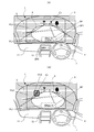
- FIG. 1 (A) shows an example of superimposed display on an object included in a front view in the daytime of the vehicle display device of the present invention
- FIG. 1 (B) shows the front view in the night
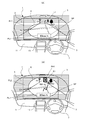
- FIG. 2A and FIG. 2B are diagrams showing another example of superimposed display on an object included in a real view in front of the display device for a vehicle of the present invention at night.
- FIG. 3 (A) shows a situation in which a person as an object walks in the direction of entering the road at night
- FIG. 3 (B) shows the front of the vehicle display device of the present invention at night.
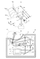
- FIG. 4A shows a setting example of the virtual image display surface in the HUD device capable of setting a plurality of surfaces (three surfaces) as a virtual image display surface
- FIG. 4B shows a configuration example of main parts of the HUD device
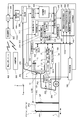
- FIG. 5 shows an example of the overall configuration of a display device for a vehicle according to the present invention, which includes at least the HUD device shown in FIGS. 4 (A) and 4 (B). It is a flowchart which shows an example of the main operation
- the display apparatus for a vehicle projects (projects) an image (in other words, display light for displaying the image) onto a projection target member (a light transmitting member) provided on the vehicle, thereby allowing the driver to display a virtual image of the image.
- a head-up display (HUD) device (not shown in FIG. 1, not shown in FIG. 1, reference numeral 100 in FIG. 5) in which a virtual image includes a virtual image of a superimposed image superimposed on a real scene around the vehicle. At least).
- FIG. 1 shows an example of superimposed display on an object included in a front view in the daytime of the vehicle display device of the present invention
- FIG. 1 (B) shows the front view in the night It is a figure which shows the example of the superimposition display to the target object contained (and the figure for demonstrating the subject of the superimposition display in night time).
- the windshield (front glass) 3 of the vehicle 1 functions as a projection target (light transmission member).
- a driver (not shown in FIG. 1) can visually recognize the real scene in front of the vehicle 1 through the windshield 3.
- the HUD device 100 (see FIG. 4A and FIG. 5) included in the vehicle 1 sets the target as “the person E1” as an alerting target included in the real view. It is possible to superimpose a virtual image (highlighted display) of the image to be emphasized.
- the “image for emphasizing the object including the frame and the like surrounding the object” is the “superimposed image” described above.
- the superimposed image is generated by an image generation unit or the like included in the HUD device 100 (described later).
- the vehicle 1 in addition to the HUD device 100, the vehicle 1 is provided with a display unit (display) 13 configured by a liquid crystal display device or the like.
- the display unit (display) 13 is provided at the center of the front panel 11.
- a mode selection switch (operation unit) 9 is provided on the steering wheel (for example, steering wheel) 7 of the vehicle 1, and the driver turns on the HUD device 100 by operating the mode selection switch (operation unit) 9. It is possible to switch (select) on / off, on / off of superimposed display, and the like.
- the driver visually recognizes the virtual image of the image formed by the HUD device 100 in front of the vehicle 1 through the windshield 3.
- a rectangular virtual image display area 5 (indicated by a broken line) is set on the surface of the windshield 3, and a virtual image can be displayed inside the virtual image display area 5.
- the virtual image of the superimposed image is superimposed within the virtual image display area 5 on the target object to be alerted.
- a second virtual image display area PL2 for displaying a virtual image of the vehicle speed display SP "60 km / h" is included.
- the second virtual image display area PL2 is, for example, an area where the position is fixed, and displays vehicle information such as the number of rotations of the engine, a warning indicating the condition of the engine oil, etc. Can be displayed.
- Target objects to be alerting candidates included in the real view around the vehicle 1 include "person E1”, “telegraph pole E2”, “tree E3”, and “white lines such as center lines”
- E4 an object
- the moving object“ person E1 ” is detected as an alerting target, and a frame (highlighted display frame) PH1 as a highlighted display is detected for this“ person E1 ”. It is superimposed.
- the driver can visually recognize the “person E1” because the vehicle travels in the daytime.
- “person E1” in FIG. 1A is an object in the bright field (in other words, Bright field object).
- the driver can visually recognize “person E1” in an instant, so the display of the highlighting frame PH1 is correct and alerting It can be recognized that the target object “person E1” is indicated, and the driver can take necessary attentional action promptly.
- the vehicle 1 is traveling on the road at night (in this case, it is assumed that it includes a light vision environment).
- the headlights of the vehicle 1 are low beam.
- the range 8 illuminated by the headlights (in other words, the illumination range of the headlights) is a range relatively close to the vehicle 1 and no light can reach far.
- FIG. 1B The situation around the vehicle 1 in FIG. 1 (B) is the same as FIG. 1 (A), but the “person E1” as the alert target is visible in the dark from the driver of the vehicle 1 It is an object in a certain dark field (dark field object), and it is difficult for the driver to visually recognize the dark field object “person E1” clearly.
- a frame (highlighted display frame) PH1 as a highlighted display is superimposed on the “person E1” as in FIG. 1A.
- the highlight display frame PH1 is accurately superimposed on the object “person E1”, which may be a useful display, but the driver can not visually recognize the “person E1”.
- the display frame PH1 is correctly superimposed on the object (in other words, the reliability or accuracy of the information presented by the display) can not be judged instantaneously. Thus, the driver may feel uneasy. In addition, it is also denied that the driver tends to view the "person E1" which is the object, so that the line of sight is concentrated in the vicinity of the "person E1" and causes a carelessness ahead. Can not.
- FIG. 2A and FIG. 2B are diagrams showing another example of superimposed display on an object included in a real view in front of the display device for a vehicle of the present invention at night.
- FIG. 2 (A) and FIG. 2 (B) the same reference numerals are given to the portions common to FIG. 1 (A) and FIG. 1 (B).
- this point is the same also in FIG. 3 (A) and FIG. 3 (B).
- the display of the highlight display frame PH1 as a superimposed display is not performed for the dark-field object “person E1”. Instead, the inside of the virtual image display area 5 is displayed.
- the displays QP1 and QP2 prompting attention to the object "person E1" called "person to the right front” It is done.
- the driver since the superimposed display is not performed on the object in the dark field, the driver does not feel anxious feeling, and another virtual image display area (second virtual image display area PL2 in the HUD device 100). And the other display unit (indicator) 13 can notify the driver that the target object requiring attention is in the dark field indirectly by making a display prompting attention. Therefore, a display device for a vehicle that can provide appropriate information while securing safe driving even when the object (for example, “person E1”) is in the dark field (night vision range) is realized.
- FIG. 2B will be referred to.
- “person E5” tries to cross the road, but at least the foot of this “person E5” is a range where the headlights illuminate brightly (lighting of the headlights Range) 8 and driver can see "person E5".
- the highlight display frame PH2 is displayed (superimposed display) so as to surround the “person E5”. Thereby, the driver can surely know that "person E5" is entering the road.
- FIG. 3 (A) shows a situation in which a person as an object walks in the direction of entering the road at night
- FIG. 3 (B) shows the front of the vehicle display device of the present invention at night.
- the further another example of the superposition display to the object contained in the real scene of 4 is shown.
- the situation around the vehicle 1 in FIG. 3 (A) is almost the same as FIG. 2 (A), but in the case of FIG. 3 (A), the object “person E1” is at a considerable speed ( In other words, I am trying to enter the road fast or running.
- the lighting (headlight etc.) provided to the vehicle 1 is controlled, or the external lighting system (external lighting 500) is controlled. It is conceivable that illumination light is emitted to the “person E1”.
- the headlamp provided in the vehicle 1 is switched from the low beam to the high beam, and thereby the illumination light has reached the "person E1", and the "person E1" is the dark field target Things are being converted to bright field objects.
- the road (outdoor) spotlight as the external light 500 is operated by remote control by wireless communication from the vehicle 1, for example, and the illumination light is changed to “person E1”. I am irradiating it.
- the “person E1” that is a dark-field and difficult-to-see object is converted to a bright-field and visible object (bright-field object), and
- superimposed display superimposition of the highlighting frame PH1
- the driver can instantly visually recognize the object (“person E1”) indicated by the superimposed display. It is. Therefore, anxious feeling does not occur and useful information can be provided.
- a lighting unit including a headlight, and other auxiliary lighting systems can be considered.
- an external lighting system for example, a road light (road lighting fixture) installed in an environment around a vehicle and capable of controlling the lighting condition using a wireless communication or the like from a vehicle in transit Spotlights, crime prevention lights, street lights etc. can be considered. It is also conceivable to use the lighting of other vehicles.
- the illumination light is irradiated to the object by changing the illumination mode
- the invention is not limited to this, and in particular, the danger Even if the target as the alerting target is detected in the dark field range as in the example of FIG. 2B, the illumination mode is unconditionally changed as in the example of FIG. 2B. Good.
- the fact may be notified by, for example, display or sound by the display 13 so as not to give the driver a feeling of suddenness (uncomfortable feeling). .
- an indirect notification may not be in time, for example, highlighting (for example, colored frames, logos, reminders, letters, etc.) of the object in the dark field may be adjusted for easy viewing. Warnings and the like may be superimposed to directly and positively indicate that there is a high-risk object in the dark field. This can prompt the driver, for example, to take prompt action to avoid danger.
- highlighting for example, colored frames, logos, reminders, letters, etc.
- FIG. 1B will be referred to again.
- the highlight display frame PH1 is superimposed on the “person E1”, but here, the “person E1” has a high risk as in the example of FIG. 3A.
- the object is determined to be Since "person E1" is in the dark field range, the driver can not view “person E1” in the present situation, but the vehicle 1 is traveling at a fairly high speed of 60 km / h. Therefore, as time passes, the vehicle 1 approaches the “person E1”, and eventually, the “person E1” enters the range (illumination range) 8 where the headlights are brightly illuminated. Can clearly view the “person E1” which is the target on which the superimposed display is made.
- the driver since the highlight display frame PH1 is displayed early since the object "person E1" is in the range of the dark field, the driver is in advance of the "person E1" having a risk. It is possible to detect the existence, and thus, it is possible to perform a collision avoidance operation such as, for example, applying a quick brake immediately when “person E1” enters the illumination range and becomes visible. As described above, it may be assumed that an effect on safe driving can be expected by performing superimposed display on an object in the dark field.
- the superimposed display may be performed on an object which is determined to have a high risk, it is not necessarily that the determination of the risk must be performed, and so on.
- the judgment may be made based on the condition of (1), and even if such a condition judgment is not made, for example, the driver can sufficiently perform the superimposed display on the object in the dark field.
- the superimposed display may be performed on the object in the dark field range without performing the determination of the degree of the danger. .
- FIG. 4A shows a setting example of the virtual image display surface in the HUD device capable of setting a plurality of surfaces as the virtual image display surface
- FIG. 4B shows a configuration example of the main part of the HUD device.
- FIGS. 4 (A) and 4 (B) the same reference numerals are given to the same parts as those in the above-mentioned drawings.
- the HUD device 100 is a three-surface (three-layer) HUD device that can use three virtual image display surfaces.
- the HUD device 100 is installed, for example, inside a dashboard of a vehicle, and emits display light K1 and K2 for displaying an image from the lower side to the upper side, whereby the image is used as a projection target member (light transmitting member). Project on the windshield 3.
- the to-be-projected member (light transmission member) 3 is not limited to a windshield, You may be other members, such as a combiner.
- the virtual image display surface PS1 (a) at a distant position is closer to the virtual image display surface PS1 (a)
- Three surfaces of the virtual image display surface PS1 (b) of L100 and the virtual image display surface PS2 of the closest position can be used.
- the virtual image display surface PS2 is a surface on which the vehicle speed display SP and the like are displayed, and the virtual image display distance L102 is fixed.
- the virtual image display surface PS1 (a), (b) is a surface on which superimposed display (highlighted display frame PH1 and the like shown above) is displayed, and the distance of the object to be superimposed is far from or near the vehicle 1
- PS1 (a) and PS (b) can be selectively switched. According to the distance to the object, by selectively switching the two surfaces, it is possible to superimpose superimposed display (emphasis display frame, etc.) on the object three-dimensionally with high accuracy without losing the sense of depth. it can.
- the virtual image display surfaces PS1 (a), PS1 (b), PS2 are erected perpendicular to the road surface 2, they are inclined at a predetermined angle with respect to the road surface 2, or It may be inclined to be superimposed.
- the HUD device 100 includes a light source unit 31 (an image generation unit 33, and a light projection control unit 35 that divides a laser beam into two to generate and output two beams).
- the mirror 39, the lens 44, and the screens 46a and 46b (having the image display surface 47 and forming the images Ma and Mb on the image display surface 47) as an image display unit; virtual image display distance control It has a portion 24 (including the lens driving portion 51 and the screen driving portion 53), a mirror 71, a reflecting mirror (concave mirror) 72, a casing 81, and a light emitting window 83.
- the entire optical system region surrounded by the broken line of an ellipse for processing the light output from the light source unit 31 is referred to as a projection optical system 37.
- the display light K1 is generated by the emitted light of the image Ma displayed on the image display surface 47 of the screen 46a
- the display light K2 is generated by the emitted light of the image Mb displayed on the image display surface 47 of the screen 46b.
- the positions of the lens 44 and the screen 46a are along the optical path, in other words, in the direction along the optical axis of the lens 44 (and the screen 46a) by the virtual image display distance control unit 24 (lens drive unit 51, screen drive unit 53).
- the virtual image display surfaces PS1 (a) and PS1 (b) can be switched as appropriate.
- the screen 46b is fixed in position, and the display light K2 is used to display the vehicle speed indication SP and the like.
- FIG. 5 is a view showing an example of the entire configuration of a display device for a vehicle according to the present invention, which includes at least the HUD device shown in FIGS. 4 (A) and 4 (B).
- FIG. 5 the same parts as those of the above-described embodiment are denoted by the same reference numerals.
- the vehicle 1 is provided with at least one camera (typically, an infrared camera 200).
- the infrared camera 200 can capture a real scene around (for example, in front of) the vehicle 1 regardless of day / night.
- a pair of infrared cameras 200 stereo cameras
- depth information distance to the object
- the vehicle 1 is provided with an external light sensor (illuminance sensor) 202 that measures the external light intensity.
- the lighting operation of the headlight (headlight) 204 provided in the vehicle 1 is controlled by the headlight control unit 203.
- a radar unit 206 is provided as necessary.
- the radar unit 206 can measure, for example, the distance to the preceding vehicle traveling in the front, and the distance (depth information) to an object present around the vehicle 1 (e.g., in the front).
- the HUD device 100 is housed inside the dashboard 4.
- the HUD device 100 includes the image generation unit 33, the light projection control unit 35, the projection optical system 37, and the virtual image display distance control unit 24 as described above.
- the HUD device 100 projects the display light K1 and K2 of the image onto a windshield (front glass) 3 as a projection target member (in other words, projects the image). Part of the projected light is directed to the driver's eye (viewpoint) A, and as a result, as shown in FIG. 4A, on the virtual image display surfaces PS1 (a), PS1 (b), PS2, A highlight display frame PH1 as a highlight display, a vehicle speed display SP, and the like are displayed.
- the highlight display frame PH1 is exactly a virtual image of an image (superimposed image: generated by, for example, the image generation unit 33) to be superimposed on the object.
- the vehicle display device includes at least the HUD device 100.
- a display unit (display) 13 using liquid crystal or the like is also provided.
- the vehicle 1 is wirelessly communicated with an electronic control unit (ECU) 300 that comprehensively controls the operation of the vehicle 1, an external driving support system 400, and an external illumination 500 as an external illumination system.
- ECU electronice control unit
- a wireless communication unit 302 capable of transmitting and receiving control signals and the like, and a vehicle information acquisition unit connected to the ECU 300 via the internal bus BUS1 and acquiring information (vehicle information) on the operation state of the vehicle 1 from the ECU 300 Based on the control signal from 304, and the headlight control part 203, it detects on / off of the headlight (headlight) 204, and detects whether the headlight 204 is a high beam or a low beam.
- Display control unit 340 for overall control of the display operation of the display device for display, a display control unit 352 for controlling the display operation of the display unit (display) 13, and an image to be displayed on the display unit (display) 13 It has the image generation part 350 which produces
- the display control unit 340 can be configured by a CPU, an MPU, and the like.
- the display control unit 340 communicates with the image generation unit 350 and the image generation unit 33 of the HUD device 100 and the virtual image display distance control unit 24 via the internal bus BUS2 to exchange data and control signals. it can.
- the clear vision range determination unit 308 determines the clear vision range around the vehicle 1 with reference to the determination result by the day and night determination unit 307 and the detection result of the high beam / low beam detection unit 306. For example, in the case of noon, in principle, it can be determined that all the surroundings are the range of the bright field (the bright vision range). Further, in the case of night, for example, the clear vision range can be determined based on the illumination range (the distribution of illumination light in space: known) of the high beam / low beam of the headlight 204.
- the object information acquisition unit 310 analyzes an image captured by the infrared camera 200, and detects an object that is an alerting target using a method such as pattern matching and feature amount extraction; The image is analyzed, and the position information of the object (for example, a direction corresponding to the lateral direction of the front vehicle 1 is taken as x direction, a direction corresponding to the up and down direction as y direction, a direction corresponding to the front of the vehicle 1 as z direction
- Position information acquisition unit 314 for acquiring coordinate information of each coordinate axis, a depth information acquisition unit 316 for acquiring information on a distance to the object (distance in the z-axis direction), and a motion detection unit for the object And 318.
- the depth information acquisition unit 316 may acquire depth information using the measurement result of the radar unit 206, or may calculate the depth information by calculation based on parallax images of the pair of infrared cameras 200.
- the motion detection unit 318 may detect a motion vector, for example, based on the difference between a plurality of captured images measured at predetermined time intervals. In this case, an aspect of the movement of the object can be detected from the direction and the magnitude of the motion vector.
- the brightness / darkness determination unit of the object includes the range (brightness range) of the bright field specified by the bright vision range determination unit 308 and the position information (coordinate information about the object acquired by the object acquisition unit 310).
- various other information can also be referred to) based on at least one of, for example, the range of the bright field in which the object is a bright range as viewed from the driver by matching and matching the two. Whether it is in the (bright vision range) (in other words, it is a bright field object) or in a dark range (dark vision range) that is a dark range (in other words, it is a dark field object) judge.
- the range of bright field in other words, the distribution of light
- the range of bright field and the position information of the detected object are compared (for example, the correspondence between the two is checked; specifically, for example, at least a part of the object
- the lightness / darkness of the object is determined by detecting whether or not it is included in the clear vision range.
- the brightness and darkness of the object can be accurately determined in consideration of the distribution of brightness around the vehicle. For example, in the daytime, regardless of the lighting state of the headlight 204, it may be determined that the surrounding objects are in the bright range. In other words, even if the headlight 204 is on, for example, if the ambient light sensor 202 determines that the surroundings are bright (daytime), the object is bright field regardless of the illumination range of the headlight 204. It can be determined that the object is in the range (bright vision range).
- the brightness of the object is considered in consideration of the range of illumination by the headlight 204 and the like. Determine It may be assumed that a camera different from the infrared camera 200 is prepared and the brightness distribution of the image taken by the camera is examined to determine the contrast of the object, but in this case as well, Since the position of the object and the luminance information at the position are associated with each other to determine the brightness of the object, it is included in the above technical range.
- the degree-of-risk determination unit 330 determines the degree of risk (the degree of risk) of the target based on the information on the movement of the target. For example, as described above with reference to FIG. 3 (A), when a person is trying to enter a road with a fast pace, etc., the person who is the object is determined to have a high risk (risk). Ru.
- the display control unit 340 determines whether or not to perform superimposed display based on the determination result of the light / dark determination unit 320 of the object, etc., and an image for notifying the driver of the superimposed display necessity determination unit 342
- the HUD display / display unit determination unit 344 determines whether the display is performed using the HUD device 100 or using the display unit (display unit) 13 (or both of them), Aspect or format of display for superimposed display or notification (for example, using frame display as superimposed display, using reminder mark, or using logo mark as display for notification, using character information, or As in the example of FIG. 3B, a notification type / display type determination unit 346 which determines that illumination light is irradiated to an object in a dark field to perform superimposed display is included.
- the illumination control unit 360 determines that the notification type / display type determination unit 346 emits illumination light to an object in the dark field to perform superimposed display
- headlight control Instruct the unit 203 to change the illumination direction of the headlight 204 (switch from low beam to high beam etc.) or instruct the ECU 300 to transmit a control signal from the wireless communication unit 302 to the external illumination 500
- the illumination light from the external illumination 500 is emitted to the object.
- the display apparatus for vehicles has the HUD apparatus 100 at least, and the object detection part 312 which detects the object as attention raising object contained in the front real view around the vehicle 1, and the detected object
- An object light / dark determination unit 320 that determines whether an object is in a bright field which is a bright area or a dark field which is a dark area when viewed from the driver of the vehicle 1;
- a display control unit 340 that controls display of the image.
- the HUD device 100 superimposes the virtual image of the superimposed image on the object (FIG. 1 (A)).
- the vehicle control unit 340 determines, for example, the object of the virtual image (emphasis display frame etc.) of the superimposed image in the HUD device 100 Without superimposing on an object (FIG. 2 (A)), or in the HUD device 100, superimposing the virtual image (such as a highlighted display frame) of the superimposed image on the object in the first virtual image display region PL1 Instead, the driver is made to draw attention to an object in the dark field by displaying a virtual image in the second virtual image display region PL2 instead (FIG.
- the driver is alerted to the object in the dark field by the display by the display unit (display) 13 (see FIG. A)) or object detection Based on the information (for example, movement or movement) regarding the object detected by 312, the degree-of-risk determination unit 330 determines the degree of danger of the object, and when it is determined that the degree of danger is low When it is determined that the virtual image of the superimposed image is not superimposed on the object in the HUD device 100 and the risk is determined to be high, the object of the virtual image of the superimposed image in the HUD device 100 is exceptionally exceptional.
- the driver is notified of the presence of the object by various display modes such as superimposing (FIG. 1 (B)).
- the superimposed display is not performed on the object in the dark field, the driver does not feel anxious feeling, and the other virtual image display area (second virtual image display area PL2) in the HUD device 100 and the other
- the display unit (display unit) 13 By providing the display unit (display unit) 13 with a display prompting attention, it is possible to indirectly notify the driver that there is an object requiring attention in the dark field. Therefore, it is possible to realize a display device for a vehicle capable of providing appropriate information while securing safe driving even when the object is in the dark field (night vision range).
- the display control unit 340 determines the level of the danger of the object based on the information on the object (for example, based on the movement of the object, the manner of movement, etc.), and it is determined that the danger is high.
- the information on the object for example, based on the movement of the object, the manner of movement, etc.
- the danger is high.
- a person who is the object enters a road, or a bicycle traveling diagonally forward is moving toward the center line little by little
- superimposition (superimposed display) of virtual images can be performed even on an object in the dark field. In such a case, there is a possibility that the indirect notification by the display of the other virtual image display area (second virtual image display area PL2) or the other display unit (display) 13 may not be in time.
- An object with high risk of being displayed in the dark field is superimposed with highlighting (for example, colored frame, logo, warning mark, warning by letters, etc.) adjusted for easy viewing. Directly and positively indicate that there is This can prompt the driver, for example, to take prompt action to avoid danger.
- highlighting for example, colored frame, logo, warning mark, warning by letters, etc.
- the display control unit 340 determines that the target is in the dark field by the contrast determination unit 320 of the target, or the risk determination unit 330 determines that the risk of the target is high.
- the lighting condition is doubled (when the condition is doubled)
- the lighting system provided in the vehicle is controlled through the headlight control unit 203 as the first light control unit or the lighting system outside the vehicle 1 is controlled.
- the object may be illuminated with illumination light, thereby making the object in the dark field the object in the bright field and superimposing the virtual image of the superimposed image on the object in the bright field (FIG. B) Example).
- the illumination light is forcibly irradiated to the object in the dark field (dark field object), thereby converting the dark field object into the object in the bright field (bright field object)
- Lighting of the host vehicle for example, a lighting unit including a headlight, a lighting system
- an external lighting system for example, a road light (road lighting fixture) installed in the environment around the vehicle, outdoor spotlights, Illuminate objects using crime prevention lights, street lights, etc.
- the driver can instantly view the object shown by the superimposed display. Therefore, anxious feeling does not occur and useful information can be provided.
- the low beam of the headlight can be switched to the high beam.
- the processing load on the device is considerably heavy, and the driver may also feel discomfort due to the forced change of the lighting state. It is desirable that consideration is given to changing the lighting mode only when it is carefully judged that the risk is high.
- the driver may be informed of the fact by display, sound or the like to reduce the discomfort.
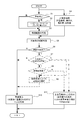
- FIG. 6 is a flowchart showing an example of the main operation procedure of the display device for a vehicle shown in FIG.
- day and night judgment is performed (step S1). If it is determined in step S1 that there is a night, next, information on the high beam / low beam is input (step S2). When it is determined in step S1 that it is noon, the process proceeds to step S3.
- step S3 the determination of the bright vision range (the range of the bright field or the range in which the driver looks bright) is performed.
- object information position information, depth information, information such as movement, etc.
- step S5 the brightness / darkness of the object is determined (step S5), and when it is an object (bright field object) within the bright vision range (bright field range),
- step 10 the brightness / darkness of the object is determined (step S5), and when it is an object (bright field object) within the bright vision range (bright field range).
- step 10 the process shifts to step 10 to perform superimposed display (display of a frame superimposed on the object, a warning mark, a logo, etc.) on the object.
- step S6 When it is determined in step S6 that the object is in the dark vision range (dark field range) (dark field target) (Y in step S6), in principle, superimposed display is not performed. Then, the process proceeds to step S11, and notification to the driver by non-overlapping display is performed using the second virtual image display area of the HUD device or another display unit (display unit).
- step S10 may perform superimposed display, for example, may shift to step S11 to notify the driver by non-superimposed display, or shift to step S9 to change the illumination ( The subject may be illuminated by a forced change of the illumination aspect).
- step S8 following step S7, it may be determined whether or not it is necessary to change the illumination (forced change of the illumination mode).
- the illumination change is determined in step S9.
- the object may be illuminated by (forced change of the illumination mode), and then transition may be made to step S10 to perform superimposed display on the object within the range of the bright field.
- an object to be detected may be a road sign, a landmark serving as a mark useful for reaching a destination, or the like, as well as a person or a moving object such as a bicycle.
- the change of the illumination mode may be performed not only for the headlights but also for backlights and other preliminary illumination lights.
- the highlight display frame is described as an example of the superimposed display. However, for example, an arrow pointing to an object, a logo or the like may be included in the superimposed display.
- the display in the display on the HUD device or another display unit (display) may be performed in a mode different from the normal display mode.
- notification may be performed using a character, an icon indicating the degree of risk or type of the object, or the like.
- HUD device 200 ⁇ ⁇ Infrared camera, 202 ⁇ ⁇ ⁇ ambient light sensor (illuminance sensor), 203 ⁇ ⁇ ⁇ ⁇ ⁇ headlight control unit, 204 ⁇ ⁇ ⁇ ⁇ ⁇ ⁇ ⁇ ⁇ ⁇ ⁇ ⁇ ⁇ ⁇ ⁇ ⁇ ⁇ ⁇ ⁇ ⁇ ⁇ ⁇ ⁇ ⁇ ⁇ ⁇ ⁇ ⁇ ⁇ ⁇ ⁇ ⁇ ⁇ ⁇ ⁇ ⁇ ⁇ ⁇ ⁇ ⁇ ⁇ ⁇ ⁇ ⁇ ⁇ ⁇ ⁇ ⁇ ⁇ ⁇ ⁇ ⁇ ⁇ ⁇ ⁇ ⁇ ⁇ ⁇ ⁇ Wireless communication unit, 304 ⁇ ⁇ ⁇ vehicle information acquisition unit, 306 ⁇ ⁇ ⁇ high beam / low beam detection unit, 307 ⁇ ⁇ ⁇ ⁇ ⁇ ⁇ ⁇ ⁇ ⁇ ⁇ ⁇ ⁇ ⁇ ⁇ ⁇ ⁇ ⁇ ⁇ ⁇ ⁇ ⁇ ⁇ ⁇ ⁇ ⁇ ⁇
Landscapes
- Physics & Mathematics (AREA)
- General Physics & Mathematics (AREA)
- Instrument Panels (AREA)
Abstract
L'invention concerne un dispositif d'affichage pour véhicules qui permet, lors de l'affichage d'une image virtuelle superposée sur un objet, de fournir des informations appropriées tout en garantissant une conduite sûre même lorsque l'objet est dans la plage de vision nocturne. Ce dispositif d'affichage comprend : une unité de détection d'objet (312) permettant de détecter un objet tête haute; une unité de détermination de lumière/obscurité d'objet (320); et une unité de commande d'affichage (340). Lorsqu'un objet est dans la plage de vision nocturne, l'unité de commande d'affichage (340) exécute une commande d'affichage de façon à ne pas autoriser l'affichage superposé d'une image virtuelle PH1 au moyen d'un dispositif d'affichage tête haute (HUD) (100) ou effectuer un affichage tête haute associé dans une autre zone ou sur un autre dispositif d'affichage (13) ou effectuer un affichage superposé lorsqu'il est déterminé qu'un objet est très dangereux d'après le mouvement de celui-ci.
Applications Claiming Priority (2)
| Application Number | Priority Date | Filing Date | Title |
|---|---|---|---|
| JP2017-160586 | 2017-08-23 | ||
| JP2017160586 | 2017-08-23 |
Publications (1)
| Publication Number | Publication Date |
|---|---|
| WO2019039201A1 true WO2019039201A1 (fr) | 2019-02-28 |
Family
ID=65438758
Family Applications (1)
| Application Number | Title | Priority Date | Filing Date |
|---|---|---|---|
| PCT/JP2018/028473 Ceased WO2019039201A1 (fr) | 2017-08-23 | 2018-07-30 | Dispositif d'affichage pour véhicules |
Country Status (1)
| Country | Link |
|---|---|
| WO (1) | WO2019039201A1 (fr) |
Cited By (3)
| Publication number | Priority date | Publication date | Assignee | Title |
|---|---|---|---|---|
| JP2020163942A (ja) * | 2019-03-28 | 2020-10-08 | パナソニックIpマネジメント株式会社 | 表示装置 |
| WO2020230418A1 (fr) * | 2019-05-14 | 2020-11-19 | パナソニックIpマネジメント株式会社 | Dispositif d'affichage |
| WO2025088787A1 (fr) * | 2023-10-27 | 2025-05-01 | 三菱電機モビリティ株式会社 | Dispositif d'aide à la conduite |
Citations (8)
| Publication number | Priority date | Publication date | Assignee | Title |
|---|---|---|---|---|
| JP2006318677A (ja) * | 2005-05-10 | 2006-11-24 | Toyota Motor Corp | 照射装置及び暗視装置 |
| JP2011091549A (ja) * | 2009-10-21 | 2011-05-06 | Toyota Motor Corp | 車両用夜間視界支援装置 |
| WO2011108218A1 (fr) * | 2010-03-01 | 2011-09-09 | 本田技研工業株式会社 | Dispositif de surveillance de zone environnante pour véhicule |
| JP2011227657A (ja) * | 2010-04-19 | 2011-11-10 | Honda Motor Co Ltd | 車両の周辺を監視する装置 |
| WO2012164729A1 (fr) * | 2011-06-02 | 2012-12-06 | トヨタ自動車株式会社 | Dispositif d'assistance de champ de vision de véhicule |
| JP2014127924A (ja) * | 2012-12-27 | 2014-07-07 | Denso Corp | 暗視装置 |
| WO2015025350A1 (fr) * | 2013-08-19 | 2015-02-26 | 三菱電機株式会社 | Dispositif de commande d'affichage monté sur véhicule |
| JP2015049842A (ja) * | 2013-09-04 | 2015-03-16 | トヨタ自動車株式会社 | 注意喚起表示装置及び注意喚起表示方法 |
-
2018
- 2018-07-30 WO PCT/JP2018/028473 patent/WO2019039201A1/fr not_active Ceased
Patent Citations (8)
| Publication number | Priority date | Publication date | Assignee | Title |
|---|---|---|---|---|
| JP2006318677A (ja) * | 2005-05-10 | 2006-11-24 | Toyota Motor Corp | 照射装置及び暗視装置 |
| JP2011091549A (ja) * | 2009-10-21 | 2011-05-06 | Toyota Motor Corp | 車両用夜間視界支援装置 |
| WO2011108218A1 (fr) * | 2010-03-01 | 2011-09-09 | 本田技研工業株式会社 | Dispositif de surveillance de zone environnante pour véhicule |
| JP2011227657A (ja) * | 2010-04-19 | 2011-11-10 | Honda Motor Co Ltd | 車両の周辺を監視する装置 |
| WO2012164729A1 (fr) * | 2011-06-02 | 2012-12-06 | トヨタ自動車株式会社 | Dispositif d'assistance de champ de vision de véhicule |
| JP2014127924A (ja) * | 2012-12-27 | 2014-07-07 | Denso Corp | 暗視装置 |
| WO2015025350A1 (fr) * | 2013-08-19 | 2015-02-26 | 三菱電機株式会社 | Dispositif de commande d'affichage monté sur véhicule |
| JP2015049842A (ja) * | 2013-09-04 | 2015-03-16 | トヨタ自動車株式会社 | 注意喚起表示装置及び注意喚起表示方法 |
Cited By (4)
| Publication number | Priority date | Publication date | Assignee | Title |
|---|---|---|---|---|
| JP2020163942A (ja) * | 2019-03-28 | 2020-10-08 | パナソニックIpマネジメント株式会社 | 表示装置 |
| JP7236674B2 (ja) | 2019-03-28 | 2023-03-10 | パナソニックIpマネジメント株式会社 | 表示装置 |
| WO2020230418A1 (fr) * | 2019-05-14 | 2020-11-19 | パナソニックIpマネジメント株式会社 | Dispositif d'affichage |
| WO2025088787A1 (fr) * | 2023-10-27 | 2025-05-01 | 三菱電機モビリティ株式会社 | Dispositif d'aide à la conduite |
Similar Documents
| Publication | Publication Date | Title |
|---|---|---|
| JP6346614B2 (ja) | 情報表示システム | |
| US8536995B2 (en) | Information display apparatus and information display method | |
| US10134283B2 (en) | Road surface image-drawing system for vehicle | |
| JP6413207B2 (ja) | 車両用表示装置 | |
| JP6272375B2 (ja) | 車両用表示制御装置 | |
| JP5338273B2 (ja) | 画像生成装置、ヘッドアップディスプレイ装置および車両用表示装置 | |
| JP6379779B2 (ja) | 車両用表示装置 | |
| JP4943367B2 (ja) | 車両用情報表示装置 | |
| US12351099B2 (en) | Vehicle display system, vehicle system, and vehicle | |
| JP7111582B2 (ja) | ヘッドアップディスプレイシステム | |
| JP2017170933A (ja) | 車両用表示制御装置 | |
| JP2013032087A (ja) | 車両用ヘッドアップディスプレイ | |
| US9776559B2 (en) | Vehicular display system | |
| JP6448714B2 (ja) | 情報表示システム | |
| KR20250095715A (ko) | 차량용 표시 장치 및 화상 표시 방법 | |
| US20160225186A1 (en) | System and method for augmented reality support | |
| JP2009292223A (ja) | 車両用警告表示装置 | |
| JP2010039793A (ja) | 車両用表示装置 | |
| JP2021154888A (ja) | 車両用表示装置 | |
| WO2019039201A1 (fr) | Dispositif d'affichage pour véhicules | |
| JP5192009B2 (ja) | 車両の周辺監視装置 | |
| JP5686042B2 (ja) | 車両周辺表示装置 | |
| JP5578254B2 (ja) | 画像生成装置 | |
| JP2018087852A (ja) | 虚像表示装置 | |
| JP2012066646A (ja) | 表示装置 |
Legal Events
| Date | Code | Title | Description |
|---|---|---|---|
| 121 | Ep: the epo has been informed by wipo that ep was designated in this application |
Ref document number: 18848778 Country of ref document: EP Kind code of ref document: A1 |
|
| NENP | Non-entry into the national phase |
Ref country code: DE |
|
| 122 | Ep: pct application non-entry in european phase |
Ref document number: 18848778 Country of ref document: EP Kind code of ref document: A1 |
|
| NENP | Non-entry into the national phase |
Ref country code: JP |