WO2019043835A1 - Dispositif électronique - Google Patents
Dispositif électronique Download PDFInfo
- Publication number
- WO2019043835A1 WO2019043835A1 PCT/JP2017/031181 JP2017031181W WO2019043835A1 WO 2019043835 A1 WO2019043835 A1 WO 2019043835A1 JP 2017031181 W JP2017031181 W JP 2017031181W WO 2019043835 A1 WO2019043835 A1 WO 2019043835A1
- Authority
- WO
- WIPO (PCT)
- Prior art keywords
- vertical direction
- electronic device
- phase refrigerant
- coo
- heating element
- Prior art date
- Legal status (The legal status is an assumption and is not a legal conclusion. Google has not performed a legal analysis and makes no representation as to the accuracy of the status listed.)
- Ceased
Links
Images








Classifications
-
- G—PHYSICS
- G06—COMPUTING OR CALCULATING; COUNTING
- G06F—ELECTRIC DIGITAL DATA PROCESSING
- G06F1/00—Details not covered by groups G06F3/00 - G06F13/00 and G06F21/00
- G06F1/16—Constructional details or arrangements
- G06F1/20—Cooling means
-
- H—ELECTRICITY
- H05—ELECTRIC TECHNIQUES NOT OTHERWISE PROVIDED FOR
- H05K—PRINTED CIRCUITS; CASINGS OR CONSTRUCTIONAL DETAILS OF ELECTRIC APPARATUS; MANUFACTURE OF ASSEMBLAGES OF ELECTRICAL COMPONENTS
- H05K7/00—Constructional details common to different types of electric apparatus
- H05K7/20—Modifications to facilitate cooling, ventilating, or heating
Definitions
- the present invention relates to an electronic device, for example, an electronic device for cooling a heating element.
- Patent Document 1 As a technique for cooling a heating element, an electronic device capable of cooling the heating element using a dielectric coolant is known (for example, Patent Document 1).
- the electronic device described in Patent Document 1 circulates a dielectric cooling liquid between a container and a heat exchanger to cool a heating element (operating parts) in the container.
- the heat exchanger is provided outside the container.
- the heating element is mounted on a circuit board (motherboard).
- a dielectric coolant is stored in the vessel.
- the circuit board on which the heating element is mounted is immersed in the dielectric coolant in the container.
- the dielectric coolant is circulated in the vessel and between the heat exchangers by the power of the pump.
- the electronic device described in Patent Document 1 operates as follows. First, the heat of the heating element is absorbed by the dielectric coolant in the vicinity of the heating element.
- the dielectric coolant which has absorbed the heat of the heating element is supplied to the heat exchanger by the power of the pump.
- the heat exchanger receives the heat of the heating element absorbed by the dielectric coolant and dissipates the heat to the outside air.
- the dielectric coolant is cooled by the heat exchanger and is again supplied to the heating element in the vessel. As described above, in the electronic device disclosed in Patent Document 1, the dielectric coolant is circulated between the container and the heat exchanger to cool the heating element in the container.
- a plurality of heating elements are mounted on the circuit board along the vertical direction. Also, a plurality of pin-shaped fins are mounted on each of the plurality of heating elements. The plurality of fins receive the heat of the heating element directly from the heating element itself and transfer the heat of the heating element to the dielectric coolant.
- the dielectric cooling liquid used in the electronic device described in Patent Document 1 is a refrigerant that does not change in phase between the liquid phase refrigerant (liquid phase refrigerant) and the gas phase refrigerant (gas phase refrigerant). It is used. For this reason, the gas phase refrigerant generated by the phase change of the liquid phase refrigerant due to the heat of the heat generating element did not adhere to the heat generating element or the fin.
- the fins have a pin shape
- the bubbles of the gas-phase refrigerant generated on the surfaces of the heating elements on the lower side in the vertical direction and the fins pass between the pin-shaped fins on the heating elements on the upper side in the vertical direction.
- it adheres over the entire surface of the fin on the heating element on the upper side in the vertical direction.
- the heat of the heat generating body is directly transferred from the surface of the heat generating body or fin to the liquid phase refrigerant.
- the heat of the heat generating body is transferred from the surface of the heat generating body or fin to the air bubbles of the gas phase refrigerant. Not transmitted to the liquid phase refrigerant.
- the electronic device is more likely when the gas phase refrigerant bubbles are attached to the surface of the heating element or fin than when the gas phase refrigerant bubbles are not attached to the surface of the heating element or fin.
- the heating element on the upper side in the vertical direction can not be sufficiently cooled by further adhering the gas phase refrigerant generated on the surface of the heating element on the lower side in the vertical direction and the fins.
- the present invention has been made in view of such circumstances, and an object of the present invention is to use a refrigerant that changes in phase between a liquid-phase refrigerant and a gas-phase refrigerant, and a plurality of heating elements are vertically arranged.
- An object of the present invention is to provide an electronic device capable of cooling the heating element on the upper side in the vertical direction more efficiently even when mounted on a circuit board.
- An electronic device includes a container for enclosing a refrigerant that changes phase between liquid phase refrigerant and gas phase refrigerant, and a circuit provided in the container such that the main surface extends along the vertical direction.
- a plurality of heat generating members mounted on the circuit board along the vertical direction so as to be immersed in the substrate, the liquid phase refrigerant, and a heat conductive member, and being mutually spaced along the vertical direction
- a plurality of the inner surfaces of the container are provided to extend toward the side of the inner surface of the container facing the main surface of the circuit board and attached to at least one of the plurality of heating elements It has a current plate.
- the electronic device of the present invention even when a plurality of heating elements are mounted on the circuit board along the vertical direction using the refrigerant that changes phase between the liquid phase refrigerant and the gas phase refrigerant The heating element on the upper side in the vertical direction can be cooled more efficiently.
- FIG. 2 is a transparent front view showing the configuration of the electronic device according to the first embodiment of the present invention. It is a transmission side view which penetrates and shows the composition of the 1st modification of the electronic device in a 1st embodiment of the present invention. It is a transmission front view which penetrates and shows the composition of the 1st modification of the electronic device in a 1st embodiment of the present invention. It is a permeation
- FIG. 10 is a transparent front view showing the configuration of the electronic device according to a second embodiment of the present invention. It is a permeation
- FIG. 13 is a transparent front view showing the configuration of the electronic device according to a third embodiment of the present invention. It is a perspective view which shows the structure of a flow straightening member.
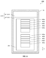
- FIG. 1A is a transparent side view showing the configuration of the electronic device 1000 in a transparent manner.
- FIG. 1B is a transparent front view showing the configuration of the electronic device 1000 in a transparent manner, showing the configuration seen through the electronic device 1000 in the direction of arrow AA of FIG. 1A.
- the vertical direction G is shown by FIG. 1A and 1B for convenience of explanation.
- the electronic device 1000 can be used, for example, as an electronic device such as a communication device or a server.
- the electronic device 1000 includes a container 100, a circuit board 200, a plurality of heating elements 300a and 300b, and a plurality of rectifying plates 400a to 400e.
- the heating element 300 is referred to as a generic name of the heating elements 300a and 300b.
- the rectifying plates 400a to 400e are collectively referred to as the rectifying plate 400.
- the container 100 is formed in a box shape.
- the inside of the container 100 is hollow.
- the container 100 is prepared to enclose a refrigerant (Coolant: hereinafter referred to as COO) which will be described in detail later.
- a refrigerant Coolant: hereinafter referred to as COO
- COO refrigerant
- a heat conductive member for example, aluminum, aluminum alloy, stainless steel
- the container 100 is provided with a lid.
- the lid is a plate that constitutes one surface of the container 100 (for example, the surface on the upper side in the vertical direction G), and is removable.
- the container 100 is completed by combining the lid and the container 100 main body.
- the lid is fixed to the main body of the container 100 by, for example, screwing.
- a rubber-like packing or the like is interposed between the lid and the container 100 main body.
- the refrigerant COO can be prevented from leaking between the lid and the container 100 main body.
- the container 100 encloses the refrigerant COO.
- the refrigerant COO includes a liquid phase refrigerant (Liquid-Phase Coolant: hereinafter referred to as LP-COO) and a gas phase refrigerant (Gas-Phase Coolant: hereinafter GP)
- LP-COO liquid phase refrigerant
- GP gas phase refrigerant
- a refrigerant that changes phase between -COO) is used.
- the refrigerant COO is enclosed in the container 100 in a sealed state. Therefore, the inside of the container 100 is always maintained at the saturated vapor pressure of the refrigerant by injecting the liquid phase refrigerant LP-COO into the container 100 and thereafter evacuating.
- FIG. 1A and 1B show a gas phase refrigerant GP-COO and a liquid phase refrigerant LP-COO sealed in a container 100.
- FIG. The gas phase refrigerant GP-COO is located in the gas phase space formed above the liquid surface of the liquid phase refrigerant LP-COO.
- the gas phase refrigerant GP-COO in the form of bubbles is generated around the heating element 300 by the phase change of the liquid phase refrigerant LP-COO into the gas phase refrigerant GP-COO by the heat of the heating element 300 described later.
- the refrigerant COO includes all the liquid phase refrigerant LP-COO and all the gas phase refrigerant GP-COO in the container 100.
- hydrofluorocarbon Hydro Fluorocarbon
- HFE Hydro Fluoroether
- the circuit board 200 is formed in a plate shape.
- the circuit board 200 is provided in the container 100 such that the main surface 201 extends along the vertical direction G.
- the circuit board 200 is fixed in the container 100 by a holding member (not shown).
- a holding member for example, a screw, a bolt, a nut or the like can be used as the holding member.
- On the circuit board 200 a plurality of heating elements 300 are attached.
- the circuit board 200 is provided in the container 100 so that at least the heating element 300 is immersed in the liquid phase refrigerant LP-COO. Thereby, the heating element 300 can be cooled by the liquid phase refrigerant LP-COO.
- the circuit board 200 may be provided in the container 100 so that substantially the entire circuit board 200 is immersed in the liquid phase refrigerant LP-COO. Thereby, the entire circuit board 200 can be cooled by the liquid phase refrigerant LP-COO.
- Circuit board 200 is, for example, a printed wiring board.
- the printed wiring board is configured by laminating a plurality of insulating substrate and conductor wiring.
- conductive pads for mounting electronic components are formed on the front and back surfaces of the printed wiring board.
- the electronic component is fixed to the pad by soldering.
- glass epoxy resin is used as a material of the substrate of the insulator.
- the conductor wiring and the pad are formed of, for example, a copper foil.
- the plurality of heating elements 300 are mounted on the circuit board 200 along the vertical direction G so as to be immersed in the liquid phase refrigerant LP-COO.
- the heating element 300 is an electronic component that emits heat when operated, and is, for example, a central processing unit (CPU) or an integrated circuit (MCM).
- the heating element 300 is a main cooling target of the electronic device 1000.
- the heat generating body 300 is fixed to the circuit board 200 by soldering or the like.
- the plurality of rectifying plates 400a to 400e are attached to at least one of the plurality of heating elements 300a and 300b.
- the plurality of current plates 400a to 400e are attached to both of the plurality of heating elements 300a and 300b.
- the plurality of current plates 400a to 400e are aligned along the vertical direction G so as to overlap each other with a gap. Further, each of the plurality of rectifying plates 400 a to 400 e is provided so as to extend toward the surface of the inner surface of the container 100 facing the main surface 201 of the circuit board 200. More specifically, in each of the plurality of rectifying plates 400a to 400e, the distance between the major surface 201 of the circuit board 200 and each of the rectifying plates 400a to 400b in the vertical direction with respect to the major surface 201 of the circuit board 200 is vertical. It is attached to heating element 300 so that it may become large gradually as it goes upwards in direction G.
- the end of the straightening vane 400 on the circuit board 200 side is fixed to the main surface of the heating element 300 by, for example, an adhesive.
- the straightening vane 400 may be fixed on the heating element 300 by being inserted into a groove (not shown) provided in the heating element 300, for example.
- hooks may be provided on the flow control plate 400, and the flow control plate 400 may be fixed to the heating element 300 using the hooks.
- the straightening vane 400 is formed of a heat conductive member.
- a metal material for example, aluminum, aluminum alloy, stainless steel
- aluminum, aluminum alloy, stainless steel is used as a material of the straightening vane 400.
- the circuit board 200 to which the heating elements 300a and 300b are attached is prepared. Then, the plurality of rectifying plates 400 are fixed to the heating elements 300a and 300b.
- the circuit board 200 is fixed in the container 100 by a holding member (not shown).
- the circuit board 200 is fixed in the container 100 such that the main surface 201 is parallel to the vertical direction G.
- a predetermined gap for example, several mm or more
- the container 100 is filled with the refrigerant COO.
- the method for filling the container 100 of the electronic device 1000 with the refrigerant COO is as follows. First, refrigerant COO is injected into the container 100 with the lid of the container 100 opened. The lid is fixed to the container 100 body. The lid is formed with an open hole. Air is removed from the interior of the container 100 using a vacuum pump (not shown) or the like through the open hole. And close the open hole. Thus, the refrigerant COO is sealed in the container 100. Thereby, the pressure in the container 100 becomes equal to the saturated vapor pressure of the refrigerant COO, and the boiling point of the refrigerant COO sealed in the container 100 becomes around room temperature.
- the heating element 300 When the electronic device 1000 is activated, the heating element 300 starts operating. Thereby, the heating element 300 generates heat. When the heating element 300 generates heat, the heat of the heating element 300 is transferred to the rectifying plate 400 and the liquid phase refrigerant LP-COO. Further, the liquid phase refrigerant LP-COO in the container 100 boils by the heat of the heating element 300 on the surface of the heating element 300 or the current plate 400, and changes its phase to a gas phase refrigerant GP-COO. In this manner, latent heat exchange takes place around the surface of the heating element 300 or the straightening vane 400, and as shown in FIG. 1A, bubbles of the gas phase refrigerant GP-COO are generated. In FIG.
- the bubbles of the gas-phase refrigerant GP-COO are not shown for convenience of drawing display.
- the heat generated by the heating element 300 is dissipated by the heat of vaporization (latent heat) generated by this phase change. Thereby, the heating element 300 is cooled.
- the gas phase refrigerant GP-COO moves upward in the liquid phase refrigerant LP-COO along each rectifying plate 400 to the upper side in the vertical direction G, passes over the liquid surface of the liquid phase refrigerant LP-COO, and further in the vertical direction G Head upwards. Then, when the gas-phase refrigerant GP-COO boiled by the heat of the heating element 300 is cooled by coming into contact with the inner wall surface of the container 100, the phase change to the liquid-phase refrigerant LP-COO again.
- the liquid-phase refrigerant LP-COO descends in the container 100 downward in the vertical direction G, accumulates on the lower side of the container 100 in the vertical direction G, and is used again to cool the heating element 300.
- the plurality of rectifying plates 400a to 400e are arranged along the vertical direction G so as to overlap each other with a gap. Further, each of the plurality of rectifying plates 400 a to 400 e is provided so as to extend toward the surface of the inner surface of the container 100 facing the main surface 201 of the circuit board 200.
- the bubbles of the gas-phase refrigerant GP-COO generated by the heat of the heating element 300b on the lower side in the vertical direction G do not go vertically to the upper side in the vertical direction G.
- the interior of the liquid-phase refrigerant LP-COO rises in a direction away from the main surface 201 of the circuit board 200 toward the side facing the main surface 201. For this reason, it is possible to suppress the flow of air bubbles of the gas-phase refrigerant GP-COO generated by the heat of the lower heating element 300b in the vertical direction G toward the upper heating element 300a in the vertical direction G.
- the bubbles of the gas-phase refrigerant GP-COO generated by the heat of the heat generating body 300b on the lower side in the vertical direction G adhere to the heat generating body 300a on the upper side in the vertical direction G or the current plate 400 attached to the heat generating body 300a. Being suppressed.
- bubbles of the gas-phase refrigerant GP-COO generated by the heat of the heating element 300a on the upper side in the vertical direction G are not vertically directed to the upper side in the vertical direction G either, but The interior of the liquid-phase refrigerant LP-COO rises in a direction away from the main surface 201 of the circuit board 200 toward the side facing the main surface 201.
- the electronic device 1000 includes the container 100, the circuit board 200, the plurality of heating elements 300, and the plurality of rectifying plates 400.
- the container 100 is for sealing a refrigerant COO that changes phase between the liquid phase refrigerant LP-COO and the gas phase refrigerant GP-COO.
- the circuit board 200 is provided in the container 100 such that the main surface 201 extends along the vertical direction G.
- the plurality of heating elements 300 are mounted on the circuit board 200 along the vertical direction G so as to be immersed in the liquid phase refrigerant LP-COO.
- the plurality of rectifying plates 400 are formed of a heat conductive member.
- the plurality of straightening vanes 400 are arranged along the vertical direction G so as to overlap with each other via a gap. Further, the plurality of rectifying plates 400 are provided to extend toward the surface of the inner surface of the container 100 facing the main surface 201 of the circuit board 200. Furthermore, the plurality of current plates 400 is attached to at least one of the plurality of heating elements 300.
- the plurality of flow straightening vanes 400 are attached to at least one of the plurality of heating elements 300, and are formed of a heat conductive member.
- the plurality of rectifying plates 400 can receive the heat of the heating element 300 and can transfer it to the liquid phase refrigerant LP-COO.
- the plurality of rectifying plates 400 are arranged along the vertical direction G so as to overlap with each other with a gap therebetween, and extend toward the surface of the inner surface of the container 100 facing the main surface 201 of the circuit board 200. It is provided as.
- the bubbles of the gas-phase refrigerant GP-COO generated by the heat of the heating element 300b on the lower side in the vertical direction G do not go vertically to the upper side in the vertical direction G.
- the interior of the liquid-phase refrigerant LP-COO rises in a direction away from the main surface 201 of the circuit board 200 toward the side facing the main surface 201. For this reason, it is possible to suppress the flow of air bubbles of the gas-phase refrigerant GP-COO generated by the heat of the lower heating element 300b in the vertical direction G toward the upper heating element 300a in the vertical direction G.
- the bubbles of the gas-phase refrigerant GP-COO generated by the heat of the heat generating body 300b on the lower side in the vertical direction G adhere to the heat generating body 300a on the upper side in the vertical direction G or the current plate 400 attached to the heat generating body 300a. Being suppressed.
- the bubbles of the gas phase refrigerant GP-COO adhere to the surfaces of the heating element 300 and the current plate 400, and the contact area between the surface of the heat element 300 and the current plate 400 and the liquid phase refrigerant LP-COO decreases. Can be suppressed. As a result, the heating element 300 can be cooled efficiently.
- the plurality of heat generating members 300 are arranged in the vertical direction G using the refrigerant COO that changes phase between the liquid phase refrigerant LP-COO and the gas phase refrigerant GP-COO. Even when mounted along the circuit board 200, the heating element 300 on the upper side in the vertical direction G can be cooled more efficiently.
- the heat of the heating element 300 is directly from the surface of the heating element 300 or the current plate 400. -It is transmitted to COO.
- the liquid phase refrigerant LP-COO is phase-changed to the gas phase refrigerant GP-COO by the heat of the heat generating body 300 to perform latent heat exchange.
- the bubbles of the gas phase refrigerant GP-COO adhere to the surface of the heating element 300 or the current plate 400, most of the heat of the heating element 300 comes from the heating element 300 or the current plate 400 Only the bubbles of the refrigerant GP-COO are transmitted.
- the bubbles of the gas-phase refrigerant attached to these surfaces receive heat of the heat generating body to perform sensible heat exchange.
- the heat of the heating element 300 is transferred to the bubbles of the gas phase refrigerant GP-COO, the bubbles of the gas phase refrigerant GP-COO expand.
- the bubbles of the gas phase refrigerant GP-COO separate from the surface of the heating element 300 or the rectifying plate 400. Then, immediately, another bubble of the gas-phase refrigerant GP-COO adheres to a place where the bubble of the gas-phase refrigerant GP-COO is released. At this time, the time when the same air bubbles of the gas phase refrigerant GP-COO adhere to the surface of the heating element 300 or the current plate 400 is short, and the air bubbles are sequentially replaced with new air bubbles. Therefore, only a small amount of heat of the heating element 300 is transferred to the liquid phase refrigerant LP-COO through the bubbles of the gas phase refrigerant GP-COO.
- the convective heat transfer coefficient due to temperature change (sensible heat) of gas phase refrigerant GP-COO is smaller than the evaporation heat transfer coefficient due to phase change (latent heat) from liquid phase refrigerant LP-COO to gas phase refrigerant GP-COO . Therefore, in the case where the bubbles of the gas phase refrigerant GP-COO adhere to the surface of the heating element 300 or the rectifying plate 400, the bubbles of the gas phase refrigerant GP-COO are on the surface of the heating element 300 or the rectifying plate 400.
- the cooling efficiency of the heating element 300 is lower than in the case of no adhesion.
- the heat of heating element 300 can be cooled more efficiently by suppressing the gas bubbles of gas-phase refrigerant GP-COO from adhering to the surface of heating element 300 or rectifying plate 400.
- the air bubbles of the gas phase refrigerant GP-COO do not adhere to the surface of the heating element 300 or the current plate 400, and the air bubbles of the gas phase refrigerant GP-COO adhere to the surface of the heating element 300 or the current plate 400
- the cooling efficiency of the heat of the heating element 300 has been described, comparing the case where there is no case.
- each of the plurality of rectifying plates 400 is the main surface 201 of the circuit board 200 in the vertical direction with respect to the main surface 201 of the circuit board 200 and each rectifying plate. It is attached to heating element 300 so that the distance between 400 may become large gradually as it goes to the upper part of perpendicular direction G.
- the bubbles of the gas-phase refrigerant GP-COO move away from the main surface 201 of the circuit board 200 while moving upward in the vertical direction G. For this reason, the bubbles of the gas-phase refrigerant GP-COO generated by the heat of the heat generating body 300b on the lower side in the vertical direction G are applied to the heat generating body 300a on the upper side in the vertical direction G Adhesion can be suppressed more reliably.
- FIG. 2A is a transparent side view showing the configuration of the electronic device 1000A.
- FIG. 2B is a transparent front view showing the structure of the electronic device 1000A in a transparent manner, showing the structure seen through the electronic device 1000A in the direction of arrow BA in FIG. 2A.
- the electronic device 1000A includes a container 100, a circuit board 200, a plurality of heating elements 300a and 300b, and a plurality of rectifying plates 400a to 400e.
- the electronic device 1000A and the electronic device 1000 are compared.
- the electronic device 1000 ⁇ / b> A is different from the electronic device 1000 in that the electronic device 1000 ⁇ / b> A includes a plurality of heat radiation fins 500.
- a plurality of heat radiation fins 500 are attached to the outside of the upper plate (the upper plate in FIG. 2A and FIG. 2B) of the container 100.
- the plurality of heat dissipating fins 500 may be integral with or separate from the container 100.
- the material of the plurality of heat radiation fins 500 is, for example, a metal material (for example, aluminum, aluminum alloy, stainless steel).
- the heat of the heat generating body 300 received by the container 100 can be dissipated to the outside air more efficiently.
- the bubbles of the gas-phase refrigerant GP-COO flow upward along the straightening vane 400 and then go upward in the vertical direction G when they pass the tip of the straightening vane 400. Therefore, when the straightening vane 400 is not in proximity to the surface of the container 100 facing the main surface 201 of the circuit board 200, most of the bubbles of the gas phase refrigerant GP-COO are included in the inner surface of the container 100. Then, it collides with the inner surface of the upper plate (the plate on the upper side of the drawing sheet in FIGS. 2A and 2B) than the surface facing the main surface 201 of the circuit board 200.
- the straightening vane 400 when the straightening vane 400 is not close to the surface of the container 100 facing the main surface 201 of the circuit board 200, the upper plate of the container 100 (plate on the upper side of the drawing in FIGS. 2A and 2B)
- the plurality of heat dissipating fins 500 By attaching the plurality of heat dissipating fins 500 to the outside of the case, it is possible to dissipate the heat of the heat generating body 300 which receives heat to the container 100 more efficiently to the outside air.
- the main surface of the circuit substrate 200 is This refers to the case where the distance between the surface facing to 201 and the tip of the current plate 400 is within several mm to several cm.
- FIG. 3A is a transparent side view transparently showing the configuration of the electronic device 1000B.
- FIG. 3B is a side view showing the configuration of the electronic device 1000B, showing the configuration of the electronic device 1000B viewed in the direction of arrow CA in FIG. 3A.
- the electronic device 1000B includes a container 100, a circuit board 200, a plurality of heating elements 300a and 300b, and a plurality of rectifying plates 400a to 400e.
- the electronic device 1000B and the electronic device 1000 are compared.
- the electronic device 1000 ⁇ / b> B differs from the electronic device 1000 in that the electronic device 1000 ⁇ / b> B has a plurality of heat radiation fins 600.
- the plurality of heat radiation fins 600 are attached to the outside of the side of the container 100 facing the main surface 210 of the circuit board 200.
- the plurality of heat dissipating fins 600 may be integral with or separate from the container 100.
- the material of the plurality of heat radiation fins 600 is, for example, a metal material (for example, aluminum, aluminum alloy, stainless steel).
- the heat of the heating element 300 received by the container 100 can be dissipated to the outside air more efficiently. That is, the heat from the heating element 300 in contact with the plate facing the main surface 210 of the circuit board 200 among the side surfaces of the container 100 is dissipated to the outside air through the plurality of heat dissipation fins 600.
- the bubbles of the gas-phase refrigerant GP-COO flow upward along the straightening vane 400 and then go upward in the vertical direction G when they pass the tip of the straightening vane 400.
- the rectifying plate 400 is close to the surface of the container 100 facing the main surface 201 of the circuit board 200, most of the bubbles of the gas-phase refrigerant GP-COO are included in the inner surface of the container 100. Then, it collides with the surface that faces the main surface 201 of the circuit board 200 than the inner surface of the upper plate (the upper plate in FIG. 2A and FIG. 2B).
- the rectifying plate 400 when the rectifying plate 400 is close to the surface of the container 100 facing the main surface 201 of the circuit board 200, the outside of the plate of the container 100 facing the main surface 201 of the circuit substrate 200 is By attaching the plurality of heat dissipating fins 600, the heat of the heat generating body 300 received by the container 100 can be dissipated to the outside air more efficiently.
- the straightening vane 400 when the straightening vane 400 is close to the surface facing the main surface 201 of the circuit board 200 among the inner surfaces of the container 100, as described above, for example, the circuit substrate among the inner surfaces of the container 100. This refers to the case where the distance between the surface facing the main surface 201 of 200 and the tip of the current plate 400 is within a few mm to a few cm.
- the radiation fin 500 may be further attached to the outside of the container 100. That is, both the radiation fin 500 and the radiation fin 600 may be attached to the outside of the container 100. Thereby, the heat from the heat generating body 300 can be dissipated to the outside air by both the heat dissipating fins 500 and the heat dissipating fins 600.
- FIG. 4A is a transparent side view showing the configuration of the electronic device 1000C.
- FIG. 4B is a transparent front view showing the configuration of the electronic device 1000C in a transparent manner, showing the configuration seen through the electronic device 1000C in the direction of arrow DA in FIG. 4A. 4A and 4B, the vertical direction G is shown for convenience of explanation.
- the electronic device 1000C includes a container 100, a circuit board 200, a plurality of heating elements 300a and 300b, and a plurality of rectifying plates 400a to 400e.
- the electronic device 1000C in the present embodiment and the electronic device 1000 in the first embodiment are compared.
- the plurality of rectifying plates 400a to 400e are attached to both the heating element 300a and the heating element 300b.
- the plurality of rectifying plates 400a to 400e are attached only to the heating element 300a on the upper side in the vertical direction G. The two differ from each other in this respect.
- the rectifying plate 400 is attached only to the upper heat generating member 300 in the vertical direction G among at least two heat generating members 300 adjacent to each other in the vertical direction G.
- the flow straightening plate 400 is not attached to the heating element 300 on the lower side in the vertical direction G.
- the heating elements 300a and 300b start operating. As a result, the heating elements 300a and 300b generate heat.
- the heating element 300a When the heating element 300a generates heat, the heat of the heating element 300a is transferred to the rectifying plate 400 and the liquid phase refrigerant LP-COO. When the heating element 300b generates heat, the heat of the heating element 300 is transferred to the liquid phase refrigerant LP-COO.
- the liquid phase refrigerant LP-COO in the container 100 boils by the heat of the heating element 300 on the surface of the heating element 300 or the current plate 400, and changes its phase to a gas phase refrigerant GP-COO.
- latent heat exchange is performed around the surface of the heating element 300 or the straightening vane 400, and as shown in FIG. 4A, bubbles of the gas phase refrigerant GP-COO are generated.
- FIG. 4B the bubbles of the gas-phase refrigerant GP-COO are not shown for convenience of drawing display.
- the heat generated by the heating element 300 is dissipated by the heat of vaporization (latent heat) generated by this phase change. Thereby, the heating element 300 is cooled.
- the plurality of straightening vanes 400a to 400e are arranged along the vertical direction G so as to overlap each other with a gap. Further, each of the plurality of rectifying plates 400 a to 400 e is provided so as to extend toward the surface of the inner surface of the container 100 facing the main surface 201 of the circuit board 200.
- the bubbles of the gas-phase refrigerant GP-COO generated by the heat of the heating element 300 a on the upper side in the vertical direction G do not go vertically to the upper side in the vertical direction G, but The interior of the liquid-phase refrigerant LP-COO rises in a direction away from the main surface 201 of the circuit board 200 toward the side facing the main surface 201.
- the bubbles of the gas-phase refrigerant GP-COO generated by the heat of the heat generating body 300b on the lower side in the vertical direction G vertically go upward to the vertical direction G immediately after generation, and the heat generating body 300a on the upper side in the vertical direction G Collide with the baffle plate 400e attached to the Then, the bubbles of the gas-phase refrigerant GP-COO generated by the heat of the heating element 300b on the lower side in the vertical direction G collide with the current plate 400e, and then along the current plate 400e
- the interior of the liquid-phase refrigerant LP-COO rises in a direction away from the main surface 201 of the circuit board 200 toward the side facing the main surface 201.
- the straightening vane 400 e is a straightening vane provided on the lowermost side in the vertical direction G among the plurality of straightening vanes 400.
- the bubbles of the gas-phase refrigerant GP-COO generated by the heat of the heat generating element 300b on the lower side in the vertical direction G are main components of the circuit board 200 on the inner surface of the container 100 along the rectifying plate 400e. It is adjusted so as to be away from the main surface 201 of the circuit board 200 toward the side facing the surface 201.
- the bubbles of the gas-phase refrigerant GP-COO generated by the heat of the lower heating element 300b in the vertical direction G are the surfaces of the upper heating element 300a in the vertical direction G (parallel to the main surface 201 of the circuit board 200). Flow towards the surface is suppressed. Therefore, the bubbles of the gas-phase refrigerant GP-COO generated by the heat of the heat generating body 300b on the lower side in the vertical direction G adhere to the heat generating body 300a on the upper side in the vertical direction G or the current plate 400 attached to the heat generating body 300a. Being suppressed.
- the electronic device 1000C according to the second embodiment of the present invention includes the container 100, the circuit board 200, the plurality of heating elements 300, and the plurality of rectifying plates 400. And have. Therefore, according to the electronic device 1000C, the same effect as the electronic device 1000 according to the first embodiment can be obtained.
- the electronic device 1000C according to the present embodiment since the rectifying plate 400 is not attached on the heat generating element 300b on the lower side in the vertical direction G, the vertical direction G is compared with the electronic device 1000 in the first embodiment. The contact area between the lower heating element 300b and the liquid phase refrigerant LP-COO decreases. Further, when the calorific value of the heat generating body 300b on the lower side in the vertical direction G is smaller than that of the heat generating body 300a on the upper side in the vertical direction G, the present embodiment can be effectively used.
- FIG. 5A is a transparent side view transparently showing the configuration of the electronic device 1000D.
- FIG. 5B is a transparent front view showing the configuration of the electronic device 1000D in a transparent manner, showing the configuration seen through the electronic device 1000D in the direction of arrow EA of FIG. 5A. 5A and 5B, the vertical direction G is shown for convenience of explanation.
- the electronic device 1000D includes a container 100, a circuit board 200, a plurality of heating elements 300a and 300b, and a plurality of rectifying plates 400a to 400e.
- the electronic device 1000D in the present embodiment and the electronic device 1000 in the first embodiment are compared.
- the plurality of rectifying plates 400a to 400e are attached to both the heating element 300a and the heating element 300b.
- the plurality of rectifying plates 400a to 400e are attached only to the heating element 300b on the lower side in the vertical direction G. The two differ from each other in this respect.
- the electronic device 1000D in the present embodiment and the electronic device 1000C in the second embodiment are compared.
- the plurality of rectifying plates 400a to 400e are attached only to the heating element 300a on the upper side in the vertical direction G.
- the plurality of rectifying plates 400a to 400e are attached only to the heating element 300b on the lower side in the vertical direction G. The two differ from each other in this respect.
- the rectifying plate 400 is attached only to the lower heat generating member 300 in the vertical direction G among at least two heat generating members 300 adjacent to each other in the vertical direction G.
- the flow straightening plate 400 is not attached to the heating element 300 on the upper side in the vertical direction G.
- the heating elements 300a and 300b start operating. As a result, the heating elements 300a and 300b generate heat.
- the heating element 300a When the heating element 300a generates heat, the heat of the heating element 300 is transferred to the liquid phase refrigerant LP-COO.
- the heating element 300b When the heating element 300b generates heat, the heat of the heating element 300b is transferred to the rectifying plate 400 and the liquid phase refrigerant LP-COO.
- the liquid phase refrigerant LP-COO in the container 100 boils by the heat of the heating element 300 on the surface of the heating element 300 or the current plate 400, and changes its phase to a gas phase refrigerant GP-COO.
- latent heat exchange is performed around the surface of the heating element 300 or the straightening vane 400, and bubbles of the gas phase refrigerant GP-COO are generated as shown in FIG. 5A.
- FIG. 5B the bubbles of the gas-phase refrigerant GP-COO are not shown for convenience of drawing display.
- the heat generated by the heating element 300 is dissipated by the heat of vaporization (latent heat) generated by this phase change. Thereby, the heating element 300 is cooled.
- the gas phase refrigerant GP-COO generated around the heating element 300a on the upper side in the vertical direction G goes almost vertically upward in the vertical direction G, passes over the liquid surface of the liquid phase refrigerant LP-COO, and is further vertical direction Head over G.
- the gas phase refrigerant GP-COO generated around the heating element 300b on the lower side in the vertical direction G travels the inside of the liquid phase refrigerant LP-COO along the rectifying plates 400 to the upper side in the vertical direction G, and the liquid phase refrigerant LP -Go above the liquid surface of COO and go upward in the vertical direction G.
- the plurality of rectifying plates 400a to 400e are arranged along the vertical direction G so as to overlap each other with a gap. Further, each of the plurality of rectifying plates 400 a to 400 e is provided so as to extend toward the surface of the inner surface of the container 100 facing the main surface 201 of the circuit board 200.
- the bubbles of the gas-phase refrigerant generated by the heat of the heating element 300b on the lower side in the vertical direction G are not directed vertically to the upper side in the vertical direction G, but along the straightening vane 400
- the inside of the liquid-phase refrigerant LP-COO rises in the direction away from the main surface 201 of the circuit board 200 toward the surface side facing the main surface 201 of the circuit board 200.
- the bubbles of the gas-phase refrigerant GP-COO generated by the heat of the heat generating element 300b on the lower side in the vertical direction G vertically go to the upper side in the vertical direction G after passing the tip of the current plate 400.
- the bubbles of the gas-phase refrigerant GP-COO generated by the heat of the heating element 300a on the upper side in the vertical direction G vertically go upward in the vertical direction G immediately after generation.
- the bubbles of the gas-phase refrigerant GP-COO generated by the heat of the lower heating element 300b in the vertical direction G are the surfaces of the upper heating element 300a in the vertical direction G (parallel to the main surface 201 of the circuit board 200). Flow towards the surface is suppressed. Therefore, the bubbles of the gas-phase refrigerant GP-COO generated by the heat of the heat generating body 300b on the lower side in the vertical direction G adhere to the heat generating body 300a on the upper side in the vertical direction G or the current plate 400 attached to the heat generating body 300a. Being suppressed.
- the electronic device 1000D according to the third embodiment of the present invention includes the container 100, the circuit board 200, the plurality of heating elements 300, and the plurality of rectifying plates 400. And have. Therefore, according to the electronic device 1000D, the same effect as the electronic device 1000 according to the first embodiment can be obtained.
- the rectifying plate 400 is not attached on the heating element 300a on the upper side in the vertical direction G, so compared with the electronic device 1000 in the first embodiment, the vertical direction G The contact area between the heating element 300a on the upper side and the liquid phase refrigerant LP-COO is reduced. Further, when the calorific value of the heating element 300a on the upper side in the vertical direction G is smaller than that of the heating element 300b on the lower side in the vertical direction G, the present embodiment can be effectively used.
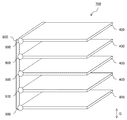
- FIG. 6 is a perspective view showing the configuration of the flow control member 700. As shown in FIG.
- the plurality of rectifying plates 400 are directly attached to the heating element 300.
- the flow control member 700 including the plurality of flow control plates 400 may be attached to the heating element 300.
- the flow straightening member 700 includes a plurality of flow straightening plates 400, a base plate 800, and a hinge 900.
- the vertical direction G is shown in FIG. 6 for the convenience of the description.
- the rectifying member 700 is attached to one or both of the heating element 300 a on the upper side in the vertical direction G and the heating element 300 b on the lower side in the vertical direction G.
- Each of the plurality of straightening vanes 400 is attached to the base plate 800 via a hinge 900.
- the plurality of straightening vanes 400 are arranged so as to overlap each other via a gap.
- the base plate 800 is formed in a flat plate shape.
- a heat conductive member for example, aluminum, aluminum alloy, stainless steel.
- the hinge 900 connects the plurality of flow straightening plates 400 and the base plate 800 so that each of the plurality of flow straightening plates 400 can rotate. At this time, each of the plurality of straightening vanes 400 can rotate about the hinge 900.
- a hinge of free stop specification can be used.
- the hinge of a free stop specification means the hinge which can fix and fix the angle between the members connected with the said hinge to arbitrary angles. By using the hinge of this free stop specification, it is possible to fix the angle between the current plate 400 and the base plate 800 to an arbitrary angle and hold the current plate 400 on the base plate 800.
- a heat conductive member for example, aluminum, aluminum alloy, stainless steel
- the hinge 900 for example, LAMP torque hinge HG-TS type manufactured by Sugatsune Industrial Co., Ltd. can be used as the hinge of the free stop type.
- the rigidity of the plurality of straightening vanes 400 between the straightening vanes 400 adjacent to each other is increased. It is connected by the wire (not shown) which it has. Thereby, all of the plurality of flow regulating plates 400 can interlockably rotate about the hinge 900. At this time, the angle formed between each of the plurality of flow regulating plates 400 and the base plate 800 is the same.
- the surface of the base plate 800 to which the rectifying plate 400 is not attached is fixed to the surface of the heating element 300 by an adhesive.
- a hook may be provided on the base plate 800, and the base plate 800 may be fixed to the heating element 300 using the hook. Thereby, the flow control member 700 can be attached to the heating element 300.
- the plurality of flow control plates 400 can be integrally attached to the base plate 800. As a result, the plurality of flow control plates 400 can be easily attached to the heating element 300 only by fixing the base plate 800 to the heating element 300.
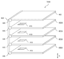
- FIG. 7 is a perspective view showing the configuration of the flow straightening member 700A.
- the vertical direction G is shown for the convenience of description.
- FIG. 8 is a plan view showing an example of the straightening vane, and is a view showing a constitution in which the straightening vane 400A is viewed in the direction of arrow Z. As shown in FIG.
- the rectifying member 700 ⁇ / b> A includes rectifying plates 400 and 400 ⁇ / b> A, a base plate 800, and a hinge 900.
- a plurality of same flow straightening plates 400 are connected to the base plate 800 by a hinge 900.
- two types of straightening vanes 400 and 400A are connected to the base plate 800 by a hinge 900. The two differ from each other in this respect.
- the straightening vane 400 does not have the through hole 410.
- the straightening vane 400A has a through hole 410.
- the straightening vane 400 without the through hole 410 is provided at the lowermost side in the vertical direction G. Further, the straightening vane 400A having the through hole 410 is provided in the vertical direction G other than the lowermost side.
- the through hole 410 is formed on the end of the straightening vane 400 ⁇ / b> A on the side of the base plate 800. Since the base plate 800 is attached to the heating element 300, the through hole 410 is formed at the end of the flow control plate 400A on the heating element 300 side. Further, the through hole 410 is disposed at the central portion in the direction along the connecting line between the straightening vane 400A and the base plate 800.
- the through holes 410 formed in at least one of the plurality of rectifying plates 400 and 400A are provided.
- the bubbles of the gas phase refrigerant GP-COO stagnating in the straightening vane 400 (or 400 A) and the liquid phase refrigerant LP-COO can flow upward in the vertical direction G through the through holes 410.
- the specific gravity of the gas phase refrigerant GP-COO is smaller than the specific gravity of the liquid phase refrigerant LP-COO. Therefore, by providing the through holes 410 in the straightening vane 400A, the bubbles of the gas phase refrigerant GP-COO flow upward in the vertical direction G via the through holes 410.
- the specific gravity of the liquid-phase refrigerant LP-COO generally tends to decrease as the temperature rises. Therefore, the liquid-phase refrigerant LP-COO stagnating on the straightening vane 400 (or 400 A) is heated by the heat of the heating element 300 and therefore flows upward in the vertical direction G through the through holes 410.
- At least one (rectifying plate 400A) of the plurality of rectifying plates 400, 400A other than the rectifying plate on the lowermost side in the vertical direction G is formed.
- the through hole 410 is provided. That is, at the lowermost side in the vertical direction G, the straightening vane 400 in which the through hole 410 is not formed is disposed.
- at least one of the straightening vanes other than the lowermost side in the vertical direction G, the straightening vane 400A having the through hole 410 is disposed.
- Such a configuration is realized, for example, by the rectifying member 700A shown in FIG. Further, in particular, when the rectifying member 700A is attached to the heating element 300a on the upper side in the vertical direction G similarly to the configuration shown in FIGS. 4A and 4B, the heating element 300 can be cooled more efficiently.
- the bubbles of the gas phase refrigerant GP-COO generated by the heat of the heating element 300a on the upper side in the vertical direction G do not go vertically to the upper side in the vertical direction G, and the circuit board 200 in the inner surface of the container 100.
- the liquid-phase refrigerant LP-COO rises in the direction away from the main surface 201 of the circuit board 200 toward the side facing the main surface 201 of FIG.
- the bubbles of the gas phase refrigerant GP-COO stagnating between the flow straightening plates of the flow straightening member 700A and the liquid phase refrigerant LP-COO flow upward in the vertical direction G via the through holes 410. Therefore, the circulation of the refrigerant COO in the container 100 can be promoted.
- the straightening vane 400A in which the through hole 410 is not formed is disposed at the lowermost side in the vertical direction G. Therefore, the bubbles of the gas-phase refrigerant GP-COO generated by the heat of the heating element 300b on the lower side in the vertical direction G are vertically directed to the upper side in the vertical direction G immediately after generation and the heating elements on the upper side in the vertical direction G It collides with the lowest current plate 400 of the straightening member 700A attached to 300a.
- the bubbles of the gas-phase refrigerant GP-COO generated by the heat of the lower heating element 300b in the vertical direction G are the surfaces of the upper heating element 300a in the vertical direction G (parallel to the main surface 201 of the circuit board 200). Flow towards the surface is suppressed. Therefore, the bubbles of the gas-phase refrigerant GP-COO generated by the heat of the heat generating body 300b on the lower side in the vertical direction G adhere to the heat generating body 300a on the upper side in the vertical direction G or the current plate 400 attached to the heat generating body 300a. Being suppressed.
- the through hole 410 is formed at the end of the rectifying plate 400A on the side of the heat generating body 300.
- the temperature is higher on the side closer to the heat generating body 300 (the root side of the straightening vane 400A) than on the side farther from the heat generating body 300 (the tip side of the straightening vane 400A).
- the amount of bubbles of the refrigerant GP-COO is large. Therefore, by forming the through holes 410 on the heat generating body 300 side of the straightening vane 400A, the bubbles of the gas phase refrigerant GP-COO can be more positively transmitted through the through holes 410 compared to the liquid phase refrigerant LP-COO. Flow to the upper side in the vertical direction G.
- the through hole 410 may be formed at the end (tip side) opposite to the heating element 300 side of the rectifying plate 400A.
- FIG. 9 is a plan view showing an example of the straightening vane, in which the through holes 410 are formed on the tip end side of the straightening vane 400B.
- a through hole 410 is formed at the end (tip side) of the straightening vane 400B on the opposite side to the heating element 300 side.
- a straightening vane 400B can be used instead of the straightening vane 400A.
- the liquid phase refrigerant LP-COO is closer than the side closer to the heating body 300 (the root side of the straightening vane 400B). There is a large amount. Therefore, by forming the through holes 410 at the end (tip) of the rectifying plate 400B on the opposite side to the heating element 300 side, the liquid phase refrigerant LP-COO can be compared with the bubbles of the gas phase refrigerant GP-COO. More positively, it can flow upward through the through hole 410 in the vertical direction G.
- two through holes 410 may be formed in the straightening vane 400C.
- FIG. 10 is a plan view showing an example of the straightening vane, showing two through holes 410 formed in the straightening vane 400C.
- a straightening vane 400C can be used instead of the straightening vane 400A.
- the first through hole 410 is formed at the end of the straightening vane 400C on the side of the heat generating body 300, as in the straightening vane 400A.
- the second through hole 410 is formed at the end (tip side) opposite to the heating element 300 side of the straightening vane 400C, as in the straightening vane 400B.
- both the effect of the straightening vane 400A and the effect of the straightening vane 400B can be exhibited. That is, by forming the through holes 410 on the heat generating body 300 side of the straightening vane 400C, the bubbles of the gas phase refrigerant GP-COO can be more positively intervened through the through holes 410 compared to the liquid phase refrigerant LP-COO. Flow to the upper side in the vertical direction G. At the same time, by forming the through hole 410 at the end (tip) of the rectifying plate 400C on the opposite side to the heating element 300 side, the liquid phase refrigerant LP-COO is compared with the bubbles of the gas phase refrigerant GP-COO. Can be more positively flowed upward through the through holes 410 in the vertical direction G.
- the through holes 420 may be formed in a slit shape so as to extend between the heat generating member 300 side of the rectifying plate 400D and the tip end side. .
- FIG. 11 is a plan view showing an example of the straightening vane, showing a slit-like through hole 420 formed in the straightening vane 400D.
- a straightening vane 400D can be used instead of the straightening vane 400A.
- the through hole 430 may be formed in a slit shape so as to extend between the heating plate 300 side of the rectifying plate 400D and the tip end side. .
- the width in the direction parallel to the main surface of the circuit board 200 is from the tip end side of the rectifying plate 400E (the opposite side of the heating element 300) to the heating element 300 side. It may be set to be larger.
- FIG. 12 is a plan view showing an example of the straightening vane, showing a through hole 430 formed in the shape of a slit and of which the length is changed in the straightening vane 400E.
- a straightening vane 400E can be used instead of the straightening vane 400A.
- both the effect of the straightening vane 400A and the effect of the straightening vane 400B can be exhibited. That is, by forming the through holes 410 in a slit shape so that the width on the heat generating body 300 side becomes large, the heat generating body 300 side of the through holes 430 is compared with the liquid phase refrigerant LP-COO, The bubbles of the gas phase refrigerant GP-COO can be more positively flown upward in the vertical direction G via the through holes 410.
- the liquid phase refrigerant LP-COO is more positively intervened through the through hole 410 in comparison with the bubbles of the gas phase refrigerant GP-COO.
- the rectifying plate 400E so that the width on the tip end side (the opposite side to the heating element 300) is reduced, the liquid phase refrigerant LP-COO is rectified at the tip end side of the rectifying plate 400E.
- the area in contact with 400E can be maximized. Therefore, the heat of the heating element 300 can be cooled more efficiently.
- FIG. 13 is a perspective view showing the configuration of the flow control member 700B.
- the vertical direction G is shown for convenience of explanation by FIG.
- the rectifying member 700 ⁇ / b> B includes rectifying plates 400 and 400 ⁇ / b> A, a base plate 800, and a hinge 900.
- a plurality of same flow straightening plates 400 are connected to the base plate 800 by a hinge 900.
- two types of straightening vanes 400 and 400A are connected to the base plate 800 by a hinge 900. The two differ from each other in this respect.
- straightening member 700A shown in FIG. 7 and the straightening member 700B shown in FIG. 13 are compared.
- the straightening vane 400 without the through hole 410 is provided at the lowermost side in the vertical direction G. Further, in addition to the flow straightener on the lowermost side in the vertical direction G, a flow straightener 400A having a through hole 410 is used.
- the straightening vane 400 having no through hole 410 is provided on the uppermost side in the vertical direction G. Further, in addition to the current plate on the uppermost side in the vertical direction G, a current plate 400A having a through hole 410 is used.
- the rectifying plate 400 having no through hole 410 is provided at the uppermost side in the vertical direction G.
- a straightening vane 400A having a through hole 410 is provided at a position other than the uppermost side in the vertical direction G.
- the through holes 410 formed in at least one of the plurality of rectifying plates 400 and 400A are provided.
- the air bubbles of the gas phase refrigerant GP-COO stagnating in the current plate 400 (or 400 A) and the liquid phase refrigerant LP-COO through the through holes 410 similarly to the effect of the first modification of the flow straightening member. Flow to the upper side in the vertical direction.
- At least one (rectifying plate 400A) of the plurality of rectifying plates 400, 400A other than the rectifying plate on the uppermost side in the vertical direction G is formed.
- the through hole 410 is provided. That is, at the uppermost side in the vertical direction G, the straightening vane 400 in which the through hole 410 is not formed is disposed. Further, except at the uppermost side in the vertical direction G, the current plate 400A having the through hole 410 is disposed in at least one of the current plates.
- Such a configuration is realized, for example, by the flow straightening member 700B shown in FIG. Further, in particular, when the rectifying member 700B is attached to the lower heating element 300b in the vertical direction G as in the configuration shown in FIGS. 5A and 5B, the heating element 300 can be cooled more efficiently.
- the bubbles of the gas-phase refrigerant GP-COO generated by the heat of the heat generating element 300a on the lower side in the vertical direction G do not go vertically to the upper side in the vertical direction G.
- the liquid-phase refrigerant LP-COO rises in the direction away from the main surface 201 of the circuit board 200 toward the side facing the main surface 201 of FIG. Further, the bubbles of the gas phase refrigerant GP-COO stagnating between the flow straightening plates of the flow straightening member 700A and the liquid phase refrigerant LP-COO flow upward in the vertical direction G via the through holes 410.
- the straightening vane 400 in which the through hole 410 is not formed is disposed at the uppermost side in the vertical direction G. Therefore, the bubbles of the gas-phase refrigerant GP-COO flowing upward in the vertical direction G through the through holes 410 and the liquid-phase refrigerant LP-COO are perpendicular to the straightening vane 400 disposed at the uppermost side in the vertical direction G. After colliding with the lower surface of G and flowing toward the tip of the straightening vane 400, it flows upward in the vertical direction G. Therefore, the circulation of the refrigerant COO in the container 100 can be promoted.
- the rectifying member 700B is not attached to the heating element 300a on the upper side in the vertical direction G. Therefore, the bubbles of the gas phase refrigerant GP-COO generated by the heat of the heating element 300a on the upper side in the vertical direction G rise in the liquid phase refrigerant LP-COO in the vertical direction to the upper side in the vertical direction G immediately after generation. Do.
- the bubbles of the gas-phase refrigerant GP-COO generated by the heat of the lower heating element 300b in the vertical direction G are the surfaces of the upper heating element 300a in the vertical direction G (parallel to the main surface 201 of the circuit board 200). Flow towards the surface is suppressed. Therefore, the bubbles of the gas-phase refrigerant GP-COO generated by the heat of the heat generating body 300b on the lower side in the vertical direction G adhere to the heat generating body 300a on the upper side in the vertical direction G or the current plate 400 attached to the heat generating body 300a. Being suppressed.
- any of the flow straightening plates 400B to 400E may be used instead of the flow straightening plate 400A.
- the effects corresponding to the shapes of the flow regulating plates 400B to 400E can be exhibited.
- FIG. 14A is a transparent side view showing the configuration of the electronic device 1000E in a transparent manner.
- 14B is a transparent front view showing the configuration of the electronic device 1000E in a transparent manner, showing the configuration seen through the electronic device 1000E in the direction of arrow FA in FIG. 14A.
- FIG. 14C is a transparent top view showing the configuration of the electronic device 1000E in a transparent manner, showing the configuration seen through the electronic device 1000E in the direction of arrow FB in FIG. 14A.
- the vertical direction G is shown for convenience of explanation.
- the electronic device 1000E includes a container 100A, a circuit board 200A, a plurality of heating elements 300a, 300b, 300c, 300d, and a plurality of rectifying plates 1400a to 1400e.
- the heating element 300 is referred to as a generic name of the heating elements 300a, 300b, 300c, and 300d.
- the rectifying plates 1400 are shown as a rectifying plate 1400 as a generic name of the rectifying plates 1400a to 1400e.
- the electronic device 1000E in the present embodiment and the electronic device 1000 in the first embodiment are compared.
- the four heating elements 300a, 300b, 300c, 300d are perpendicular to the vertical direction G and to the vertical direction G. They are mounted on the circuit board 200A so as to be parallel to each other. More specifically, the heating elements 300 a and 300 b are disposed along the vertical direction G. Similarly, the heating elements 300 c and 300 d are disposed along the vertical direction G. The heating elements 300 a and 300 c are disposed along the direction perpendicular to the vertical direction G. Similarly, the heating elements 300 b and 300 d are disposed along the direction perpendicular to the vertical direction G. In these points, the electronic device 1000E and the electronic device 1000 are different from each other.
- each of the rectifying plates 400a to 400e is attached to the heating elements 300a and 300b, respectively.
- each of the rectifying plates 1400a to 1400e connects the heating elements 300a and 300c arranged in parallel along the direction perpendicular to the vertical direction G.
- each of the rectifying plates 1400a to 1400e is attached so as to connect the heating elements 300b and 300d arranged in parallel along a direction perpendicular to the vertical direction G.
- the electronic device 1000E and the electronic device 1000 are different from each other.
- the heating elements 300a, 300b, 300c, and 300d start operating. As a result, the heating elements 300a, 300b, 300c, and 300d generate heat.
- the heat of the heating elements 300a to 300d is transferred to the current plate 400 and the liquid phase refrigerant LP-COO.
- the liquid phase refrigerant LP-COO in the container 100A boils by the heat of the heating element 300 on the surface of the heating element 300 or the rectifying plate 400, and changes its phase to a gas phase refrigerant GP-COO.
- latent heat exchange takes place around the surface of the heating element 300 or the straightening vane 400, and as shown in FIG. 14A, bubbles of the gas-phase refrigerant GP-COO are generated.
- FIG. 14B the bubbles of the gas-phase refrigerant GP-COO are not shown for convenience of drawing display.
- the heat generated by the heating element 300 is dissipated by the heat of vaporization (latent heat) generated by this phase change. Thereby, the heating element 300 is cooled.
- the gas phase refrigerant GP-COO generated around the heating elements 300b and 300d on the lower side in the vertical direction G travels upward in the liquid phase refrigerant LP-COO along the respective flow straighteners 1400 toward the upper side in the vertical direction G It goes over the liquid surface of the refrigerant LP-COO and goes upward in the vertical direction G.
- the gas phase refrigerant GP-COO generated around the heating elements 300a and 300c on the upper side in the vertical direction G travels upward in the liquid phase refrigerant LP-COO along the rectifying plates 1400 to the upper side in the vertical direction G And go upward in the vertical direction G after passing through the liquid surface of the liquid-phase refrigerant LP-COO.
- the gas-phase refrigerant GP-COO boiled by the heat of the heating element 300 is phase-changed to liquid-phase refrigerant LP-COO again when it is cooled by coming into contact with the inner wall surface of the container 100A.
- the liquid-phase refrigerant LP-COO descends in the container 100A in the vertical direction G, accumulates on the lower side of the container 100A in the vertical direction G, and is used again to cool the heat generating body 300.
- the plurality of straightening vanes 1400a to 1400e are arranged along the vertical direction G so as to overlap each other with a gap. Further, each of the plurality of rectifying plates 1400a to 1400e is provided so as to extend toward the surface of the inner surface of the container 100A facing the main surface 201 of the circuit board 200A.
- the bubbles of the gas-phase refrigerant GP-COO generated by the heat of the heat generating members 300b and 300d on the lower side in the vertical direction G do not go vertically to the upper side in the vertical direction G, but the circuit board in the inner surface of the container 100A.
- the interior of the liquid-phase refrigerant LP-COO rises in a direction away from the main surface 201 of the circuit board 200A toward the surface side facing the main surface 201 of 200A. Therefore, air bubbles of the gas-phase refrigerant GP-COO generated by the heat of the heat generating members 300b and 300d on the lower side in the vertical direction G are prevented from flowing toward the heat generating members 300a and 300c on the upper side of the vertical direction G .
- the bubbles of the gas-phase refrigerant GP-COO generated by the heat of the lower heating elements 300b and 300d in the vertical direction G are attached to the upper heating elements 300a and 300c and the heating elements 300a and 300c in the vertical direction G Adherence to the current plate 400 is suppressed.
- the bubbles of the gas-phase refrigerant GP-COO generated by the heat of the heating elements 300a and 300c on the upper side in the vertical direction G are not vertically directed to the upper side in the vertical direction G either, but the circuit board in the inner surface of the container 100A.
- the interior of the liquid-phase refrigerant LP-COO rises in a direction away from the main surface 201 of the circuit board 200A toward the surface side facing the main surface 201 of 200A.
- the bubbles of the gas phase refrigerant GP-COO generated by the heat of the heat generating members 300a and 300c on the upper side in the vertical direction G are directly transmitted to the heat generating members 300a and 300c and the rectifying plate 400 attached to the heat generating members 300a and 300c. Adhesion is suppressed.
- the electronic device 1000E according to the fourth embodiment of the present invention includes the container 100A, the circuit board 200A, the plurality of heating elements 300, and the plurality of rectifying plates 1400. And have. Therefore, according to the electronic device 1000E, the same effect as the electronic device 1000 of the first embodiment can be obtained.
- the plurality of heating elements 300 are juxtaposed along the vertical direction G and a direction perpendicular to the vertical direction G so as to be immersed in the liquid phase refrigerant LP-COO. Is mounted on the circuit board 200A.
- the rectifying plate 1400 is attached so as to connect the plurality of heating elements 300 a and 300 c parallel to the vertical direction G among the plurality of heating elements 300.
- the rectifying plate 1400 is attached so as to connect a plurality of heating elements 300 b and 300 d arranged in parallel along a direction perpendicular to the vertical direction G among the plurality of heating elements 300. Therefore, the number of parts can be reduced as compared to the case where rectifying plate 400 in the first embodiment is provided for each of a plurality of heating elements 300.
- the surface area of the straightening vane 1400 is larger than the area of two straightening vanes 400. Therefore, by using the rectifying plate 1400, the heat of the heating element 300 can be more efficiently transferred to the liquid phase refrigerant LP-COO.
- the through hole 1410 may be provided in the rectifying plate 1400A.
- FIG. 15 is a plan view showing an example of the straightening vane, and showing the through holes 1410 formed in the straightening vane 1400A.
- the rectifying plate of any of the rectifying plates 1400a to 1400d shown in FIGS. 14A and 14B can be replaced with 1400A.
- the through holes 1410 may be formed between the plurality of heating elements 300 a and 300 c arranged in parallel along a direction perpendicular to the vertical direction G. Similarly, the through holes 1410 may be formed between the plurality of heating elements 300 b and 300 d arranged in parallel along a direction perpendicular to the vertical direction G. As a result, since the through holes 1410 are formed between the heating elements 300a and 300c, it is not necessary to provide the through holes 1410 corresponding to the heating elements 300a and 300c.
- the bubbles of the gas phase refrigerant GP-COO containing the heat of both the heating elements 300 a and 300 c and the liquid phase refrigerant LP-COO can be efficiently flowed through the through holes 1410.
- the through holes 1410 are formed between the heating element 300b and the heating element 300d, it is not necessary to provide the through holes 1410 respectively corresponding to the heating elements 300b and 300d. Therefore, the bubbles of the gas phase refrigerant GP-COO containing the heat of both the heating elements 300b and 300d and the liquid phase refrigerant LP-COO can be efficiently flowed through the smaller number of through holes 1410.
- the through holes 1410 may be provided on the heat generating body 300 side, or the heat generating body 300 side may be provided on the opposite side. The effects of such an arrangement are similar to the contents described with reference to FIGS. 8 to 10.
- through holes 1410 may be provided according to each of heating elements 300a to 300d.
- the bubbles of the gas phase refrigerant GP-COO containing the heat of each heating element 300 and the liquid phase refrigerant LP-COO can flow through the respective through holes 1410. Therefore, it can suppress that the heat of heating element 300a, 300c mutually interferes.
- the heat of the heating elements 300b and 300d can be prevented from interfering with each other.
- the through hole 1410 may be provided on the heating element 300 side, or the heating element 300 side may be provided on the opposite side. The effects of such an arrangement are similar to the contents described with reference to FIGS. 8 to 10.
- a rectifying plate 1400A having a through hole 1410 may be provided in addition to the uppermost side in the vertical direction G. That is, on the uppermost side in the vertical direction G, the straightening vane 1400 in which the through hole 1410 is not formed is disposed. In addition, at least one of the straightening vanes other than the uppermost side in the vertical direction G, the straightening vane 1400A having the through hole 1410 is disposed. With such a configuration as well, the same effects as the effects described in the first modification of the flow control member can be obtained.
- a rectifying plate 1400A having a through hole 1410 may be provided in addition to the lowermost side in the vertical direction G. That is, at the lowermost side in the vertical direction G, the straightening vane 1400 in which the through hole 1410 is not formed is disposed. Further, at least one of the straightening vanes other than the lowermost side in the vertical direction G, the straightening vane 1400A having the through hole 1410 is disposed. With such a configuration, the same effects as the effects described in the second modification of the flow control member can be obtained.
- the straightening vane 1400A may be disposed on the through hole 1410 on the opposite side of the heating element 300 (on the tip end side of the straightening vane 1400A) instead of the heating element 300 side.
- the through hole 1410 may be disposed on the side opposite to the heat generating body 300 (on the tip end side of the flow correction plate 1400A).
- the shape of the through hole 1410 may be formed like a slit like the through hole 420. Further, the shape of the through hole 1410 may be formed in the same manner as the through hole 430. In these cases, the same effects as those described above can be obtained.
- a container for sealing a refrigerant that changes phase between liquid phase refrigerant and gas phase refrigerant A circuit board provided in the container such that the main surface extends in the vertical direction; A plurality of heating elements mounted on the circuit board along the vertical direction so as to be immersed in the liquid phase refrigerant; It is formed of a heat conductive member, is aligned in the vertical direction so as to overlap each other with a gap, and extends toward the surface of the inner surface of the container facing the main surface of the circuit board.
- An electronic device comprising: a plurality of rectifying plates provided and attached to at least one of the plurality of heating elements.
- Each of the plurality of rectifying plates is arranged such that the distance between the main surface of the circuit board and the rectifying plates in the direction perpendicular to the main surface of the circuit board gradually increases in the vertical direction.
- the electronic device according to claim 1 attached to the heating element.
- the electronic device according to appendix 1 or 2 further comprising a through hole formed in at least one of the plurality of flow straightening plates.
Landscapes
- Engineering & Computer Science (AREA)
- Physics & Mathematics (AREA)
- Theoretical Computer Science (AREA)
- Human Computer Interaction (AREA)
- General Engineering & Computer Science (AREA)
- General Physics & Mathematics (AREA)
- Thermal Sciences (AREA)
- Microelectronics & Electronic Packaging (AREA)
- Cooling Or The Like Of Electrical Apparatus (AREA)
- Cooling Or The Like Of Semiconductors Or Solid State Devices (AREA)
Abstract
Le problème à résoudre dans le cadre de la présente invention consiste à fournir un dispositif électronique avec lequel il est possible de refroidir plus efficacement un élément de production de chaleur côté verticalement vers le haut à l'aide d'un fluide caloporteur qui subit un changement de phase entre un fluide caloporteur en phase liquide et un fluide caloporteur en phase gazeuse, même lorsqu'une pluralité d'éléments de production de chaleur sont fixés sur une carte de circuit imprimé dans la direction verticale. La solution selon l'invention porte sur un récipient (100) qui est utilisé pour encapsuler un fluide caloporteur (COO) qui subit un changement de phase entre un fluide caloporteur en phase liquide et un fluide caloporteur en phase gazeuse. Une carte de circuit imprimé (200) est disposée dans le récipient (100) de telle sorte qu'une surface principale (201) s'étende dans une direction verticale (G). Une pluralité d'éléments de production de chaleur (300) sont fixés sur la carte de circuit imprimé (200) dans la direction verticale (G) de sorte à être immergés dans le fluide caloporteur en phase liquide. Une pluralité de plaques de redressement d'écoulement (400) sont formées à partir d'un élément thermoconducteur et agencées dans la direction verticale (G) de sorte à être placées les unes sur les autres avec un espace entre elles. La pluralité de plaques de redressement d'écoulement (400) sont disposées de sorte à s'étendre vers une section de la surface interne du récipient (100) qui fait face à la surface principale (201) de la carte de circuit imprimé (200).
Priority Applications (2)
| Application Number | Priority Date | Filing Date | Title |
|---|---|---|---|
| PCT/JP2017/031181 WO2019043835A1 (fr) | 2017-08-30 | 2017-08-30 | Dispositif électronique |
| JP2019538823A JPWO2019043835A1 (ja) | 2017-08-30 | 2017-08-30 | 電子装置 |
Applications Claiming Priority (1)
| Application Number | Priority Date | Filing Date | Title |
|---|---|---|---|
| PCT/JP2017/031181 WO2019043835A1 (fr) | 2017-08-30 | 2017-08-30 | Dispositif électronique |
Publications (1)
| Publication Number | Publication Date |
|---|---|
| WO2019043835A1 true WO2019043835A1 (fr) | 2019-03-07 |
Family
ID=65525321
Family Applications (1)
| Application Number | Title | Priority Date | Filing Date |
|---|---|---|---|
| PCT/JP2017/031181 Ceased WO2019043835A1 (fr) | 2017-08-30 | 2017-08-30 | Dispositif électronique |
Country Status (2)
| Country | Link |
|---|---|
| JP (1) | JPWO2019043835A1 (fr) |
| WO (1) | WO2019043835A1 (fr) |
Cited By (4)
| Publication number | Priority date | Publication date | Assignee | Title |
|---|---|---|---|---|
| TWI709724B (zh) * | 2019-06-12 | 2020-11-11 | 英業達股份有限公司 | 冷卻系統 |
| WO2022188860A1 (fr) * | 2021-03-12 | 2022-09-15 | 华为技术有限公司 | Dispositif de collecte de bulles |
| WO2022249939A1 (fr) * | 2021-05-24 | 2022-12-01 | 株式会社オートネットワーク技術研究所 | Appareil électrique |
| US12238893B2 (en) * | 2022-11-02 | 2025-02-25 | Fulian Precision Electronics (Tianjin) Co., Ltd. | Flow guiding device and liquid-cooled chassis with same |
Citations (2)
| Publication number | Priority date | Publication date | Assignee | Title |
|---|---|---|---|---|
| JPS61279156A (ja) * | 1985-06-05 | 1986-12-09 | Hitachi Ltd | マルチチツプモジユ−ル |
| US20140218861A1 (en) * | 2013-02-01 | 2014-08-07 | Dell Products L.P. | Vertically-Oriented Immersion Server with Vapor Bubble Deflector |
Family Cites Families (1)
| Publication number | Priority date | Publication date | Assignee | Title |
|---|---|---|---|---|
| JP2747156B2 (ja) * | 1992-03-06 | 1998-05-06 | 日本電気株式会社 | 浸漬噴流冷却用ヒートシンク |
-
2017
- 2017-08-30 JP JP2019538823A patent/JPWO2019043835A1/ja active Pending
- 2017-08-30 WO PCT/JP2017/031181 patent/WO2019043835A1/fr not_active Ceased
Patent Citations (2)
| Publication number | Priority date | Publication date | Assignee | Title |
|---|---|---|---|---|
| JPS61279156A (ja) * | 1985-06-05 | 1986-12-09 | Hitachi Ltd | マルチチツプモジユ−ル |
| US20140218861A1 (en) * | 2013-02-01 | 2014-08-07 | Dell Products L.P. | Vertically-Oriented Immersion Server with Vapor Bubble Deflector |
Cited By (4)
| Publication number | Priority date | Publication date | Assignee | Title |
|---|---|---|---|---|
| TWI709724B (zh) * | 2019-06-12 | 2020-11-11 | 英業達股份有限公司 | 冷卻系統 |
| WO2022188860A1 (fr) * | 2021-03-12 | 2022-09-15 | 华为技术有限公司 | Dispositif de collecte de bulles |
| WO2022249939A1 (fr) * | 2021-05-24 | 2022-12-01 | 株式会社オートネットワーク技術研究所 | Appareil électrique |
| US12238893B2 (en) * | 2022-11-02 | 2025-02-25 | Fulian Precision Electronics (Tianjin) Co., Ltd. | Flow guiding device and liquid-cooled chassis with same |
Also Published As
| Publication number | Publication date |
|---|---|
| JPWO2019043835A1 (ja) | 2020-09-24 |
Similar Documents
| Publication | Publication Date | Title |
|---|---|---|
| US11864348B2 (en) | Heat sink with protrusions on multiple sides thereof and apparatus using the same | |
| US20190206764A1 (en) | Thermal management component | |
| WO2018045933A1 (fr) | Dissipateur thermique, appareil de dissipation de chaleur, système de dissipation de chaleur et dispositif de communication | |
| US20140101933A1 (en) | Interchangeable cooling system for integrated circuit and circuit board | |
| WO2019043835A1 (fr) | Dispositif électronique | |
| CN101593739A (zh) | 电子设备 | |
| JP7156368B2 (ja) | 電子機器 | |
| US20220151113A1 (en) | Electronic device | |
| JP2019145749A (ja) | 電子機器および電子装置 | |
| US20200386479A1 (en) | Cooling system | |
| US20030202306A1 (en) | Heat sink for semiconductor die employing phase change cooling | |
| US8797739B2 (en) | Self circulating heat exchanger | |
| TWI497656B (zh) | 電子裝置 | |
| US20130094152A1 (en) | Electronic device and heat sink employing the same | |
| CN111384011A (zh) | 散热装置及方法 | |
| US20080142192A1 (en) | Heat dissipation device with a heat pipe | |
| WO2012161002A1 (fr) | Dispositif de refroidissement à plaques plates et son procédé d'utilisation | |
| GB2342152A (en) | Plate type heat pipe and its installation structure | |
| CN217160294U (zh) | 具有散热器的金属衬底电子元器件 | |
| US20200232714A1 (en) | Heat dissipating device | |
| CN111106079B (zh) | 散热芯片及其制作方法和电子设备 | |
| CN112885794A (zh) | 一种pcb、pop封装散热结构及其制造方法 | |
| JP2018073859A (ja) | 冷却装置、搭載方法、冷却構造 | |
| TWI492341B (zh) | 相變化散熱裝置 | |
| CN107172803B (zh) | 一种高散热的电子设备 |
Legal Events
| Date | Code | Title | Description |
|---|---|---|---|
| 121 | Ep: the epo has been informed by wipo that ep was designated in this application |
Ref document number: 17923373 Country of ref document: EP Kind code of ref document: A1 |
|
| ENP | Entry into the national phase |
Ref document number: 2019538823 Country of ref document: JP Kind code of ref document: A |
|
| NENP | Non-entry into the national phase |
Ref country code: DE |
|
| 122 | Ep: pct application non-entry in european phase |
Ref document number: 17923373 Country of ref document: EP Kind code of ref document: A1 |