WO2019043852A1 - Système de contrôle numérique et contrôleur de moteur - Google Patents
Système de contrôle numérique et contrôleur de moteur Download PDFInfo
- Publication number
- WO2019043852A1 WO2019043852A1 PCT/JP2017/031261 JP2017031261W WO2019043852A1 WO 2019043852 A1 WO2019043852 A1 WO 2019043852A1 JP 2017031261 W JP2017031261 W JP 2017031261W WO 2019043852 A1 WO2019043852 A1 WO 2019043852A1
- Authority
- WO
- WIPO (PCT)
- Prior art keywords
- disturbance
- drive shaft
- force
- tool
- model
- Prior art date
- Legal status (The legal status is an assumption and is not a legal conclusion. Google has not performed a legal analysis and makes no representation as to the accuracy of the status listed.)
- Ceased
Links
Images








Classifications
-
- G—PHYSICS
- G05—CONTROLLING; REGULATING
- G05B—CONTROL OR REGULATING SYSTEMS IN GENERAL; FUNCTIONAL ELEMENTS OF SUCH SYSTEMS; MONITORING OR TESTING ARRANGEMENTS FOR SUCH SYSTEMS OR ELEMENTS
- G05B19/00—Program-control systems
- G05B19/02—Program-control systems electric
- G05B19/18—Numerical control [NC], i.e. automatically operating machines, in particular machine tools, e.g. in a manufacturing environment, so as to execute positioning, movement or co-ordinated operations by means of program data in numerical form
- G05B19/408—Numerical control [NC], i.e. automatically operating machines, in particular machine tools, e.g. in a manufacturing environment, so as to execute positioning, movement or co-ordinated operations by means of program data in numerical form characterised by data handling or data format, e.g. reading, buffering or conversion of data
- G05B19/4086—Coordinate conversions; Other special calculations
-
- G—PHYSICS
- G05—CONTROLLING; REGULATING
- G05B—CONTROL OR REGULATING SYSTEMS IN GENERAL; FUNCTIONAL ELEMENTS OF SUCH SYSTEMS; MONITORING OR TESTING ARRANGEMENTS FOR SUCH SYSTEMS OR ELEMENTS
- G05B19/00—Program-control systems
- G05B19/02—Program-control systems electric
- G05B19/18—Numerical control [NC], i.e. automatically operating machines, in particular machine tools, e.g. in a manufacturing environment, so as to execute positioning, movement or co-ordinated operations by means of program data in numerical form
- G05B19/404—Numerical control [NC], i.e. automatically operating machines, in particular machine tools, e.g. in a manufacturing environment, so as to execute positioning, movement or co-ordinated operations by means of program data in numerical form characterised by control arrangements for compensation, e.g. for backlash, overshoot, tool offset, tool wear, temperature, machine construction errors, load, inertia
-
- G—PHYSICS
- G05—CONTROLLING; REGULATING
- G05B—CONTROL OR REGULATING SYSTEMS IN GENERAL; FUNCTIONAL ELEMENTS OF SUCH SYSTEMS; MONITORING OR TESTING ARRANGEMENTS FOR SUCH SYSTEMS OR ELEMENTS
- G05B2219/00—Program-control systems
- G05B2219/30—Nc systems
- G05B2219/33—Director till display
- G05B2219/33263—Conversion, transformation of coordinates, cartesian or polar
-
- G—PHYSICS
- G05—CONTROLLING; REGULATING
- G05B—CONTROL OR REGULATING SYSTEMS IN GENERAL; FUNCTIONAL ELEMENTS OF SUCH SYSTEMS; MONITORING OR TESTING ARRANGEMENTS FOR SUCH SYSTEMS OR ELEMENTS
- G05B2219/00—Program-control systems
- G05B2219/30—Nc systems
- G05B2219/37—Measurements
- G05B2219/37612—Transfer function, kinematic identification, parameter estimation, response
-
- G—PHYSICS
- G05—CONTROLLING; REGULATING
- G05B—CONTROL OR REGULATING SYSTEMS IN GENERAL; FUNCTIONAL ELEMENTS OF SUCH SYSTEMS; MONITORING OR TESTING ARRANGEMENTS FOR SUCH SYSTEMS OR ELEMENTS
- G05B2219/00—Program-control systems
- G05B2219/30—Nc systems
- G05B2219/42—Servomotor, servo controller kind till VSS
- G05B2219/42156—Forward dynamics model fdm
-
- G—PHYSICS
- G05—CONTROLLING; REGULATING
- G05B—CONTROL OR REGULATING SYSTEMS IN GENERAL; FUNCTIONAL ELEMENTS OF SUCH SYSTEMS; MONITORING OR TESTING ARRANGEMENTS FOR SUCH SYSTEMS OR ELEMENTS
- G05B2219/00—Program-control systems
- G05B2219/30—Nc systems
- G05B2219/45—Nc applications
- G05B2219/45044—Cutting
-
- G—PHYSICS
- G05—CONTROLLING; REGULATING
- G05B—CONTROL OR REGULATING SYSTEMS IN GENERAL; FUNCTIONAL ELEMENTS OF SUCH SYSTEMS; MONITORING OR TESTING ARRANGEMENTS FOR SUCH SYSTEMS OR ELEMENTS
- G05B2219/00—Program-control systems
- G05B2219/30—Nc systems
- G05B2219/49—Nc machine tool, till multiple
- G05B2219/49219—Compensation temperature, thermal displacement
Definitions
- the present invention relates to a numerical control system and a motor control device for controlling a machine tool.
- a machine tool is a processing device that performs removal processing, which is processing for removing unnecessary parts from a workpiece by applying force or energy to the workpiece using a tool.
- removal processing which is processing for removing unnecessary parts from a workpiece by applying force or energy to the workpiece using a tool.
- the cutting process which is one of the removal processes, by bringing the cutting edge of the tool into contact with the work at a high speed, a shear failure occurs in the work surface, and the unnecessary part of the work is cut away.
- cutting is a physical phenomenon in which the machining process and the machine dynamics interact with each other, it is desirable to simultaneously manage both in order to manage the machining state.
- the machining process represents a series of processes in which the cutting edge of the tool penetrates the workpiece to form chips while forming a machining surface.
- Machine dynamics represents the behavior of a mechanical structure when a structure that constitutes the machine is vibrated by vibration sources inside and outside the machine.
- integrated analysis is considered to be difficult because cutting is a phenomenon in which various physical phenomena including the above-described machining process and mechanical dynamics affect each other in a complex manner. For this reason, at the production site, processing control according to the purpose is achieved by limiting the evaluation object.
- the position deviation of the tool generated with respect to the ideal trajectory is evaluated, and a method of adjusting the infeed amount so as to be within the desired dimension is taken.
- the wear width of the cutting edge of the tool is evaluated to search for a cutting speed that can extend the life of the tool while maintaining the machining quality.
- a method of determining the spindle rotational speed or the feed speed such that the cutting load is not excessive is taken by acquiring the detection signal from the force sensor applied to the machine.
- the method of adjusting the cutting speed and the amount of cutting is taken by observing the shape or discharge direction of chips generated during processing.
- Patent Document 1 proposes the following method.
- processing performed by a machine tool on which a force sensor is installed is reproduced by simulation, and the cutting force reproduced by simulation is compared with the measured value of the force sensor to calculate the cutting force by simulation. Correct the machining process information to estimate the final cutting force.
- machining process information is updated using a cutting force obtained during actual machining, so that a value reflecting the machining state can be calculated.
- the present invention has been made in view of the above, and it is an object of the present invention to obtain a numerical control system capable of accurately identifying machining processes and mechanical dynamics.
- a numerical control system is a numerical control system that controls a drive shaft provided in a machine tool that performs machining using a tool according to a numerical control program And a coordinate conversion unit configured to acquire a disturbance force or disturbance torque applied to the drive shaft, coordinate-convert the disturbance force or disturbance torque to the tool reference coordinate system, and output the coordinate conversion unit. Further, this numerical control system further determines the characteristics of the processing process model using the disturbance force or disturbance torque output from the coordinate conversion unit, the drive shaft state, the predetermined relational expression, and the processing conditions.
- an identification unit that calculates a dynamic characteristic parameter that determines characteristics of a machine tool's dynamics model, and a relational expression indicates a relationship between the machining process parameter, the dynamic characteristic parameter, and the disturbance force or disturbance torque. It is a relational expression to define.
- the numerical control system according to the present invention has an effect that the machining process and the mechanical dynamics can be identified with high accuracy.
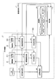
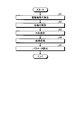
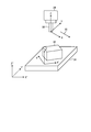
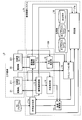
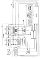
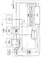
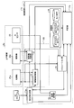
- Block diagram showing a configuration example of the numerical control system according to the first embodiment Flowchart showing an example of the operation procedure in the numerical control system according to the first embodiment The figure which shows the relationship of each coordinate system in Embodiment 1.
- Embodiment 1 when the workpiece fixed to the table vibrates due to the cutting force, a schematic diagram showing how a disturbance force is transmitted to the table
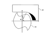
- Embodiment 1 the figure which shows an example of the rotation angle of the tool which a tool blade contacts a workpiece
- work which shows an example of the rotation angle of the tool in which the tool edge does not contact a workpiece in Embodiment 1.
- Embodiment 1 the figure which shows the mode of cutting in the 1st cutting edge in case the gap
- Embodiment 1 the figure which shows the mode of cutting in the 2nd blade edge in case the gap
- FIG. 1 the figure which shows the structural example of the processing circuit of Embodiment 1.
- FIG. 6 is a diagram showing an example of the configuration of a numerical control system according to a second embodiment Block diagram showing a configuration example of the disturbance estimation unit according to the third embodiment
- the figure which shows the estimation result of the disturbance force in a comparative example The figure which shows an example of the disturbance force estimated by the disturbance estimation part of Embodiment 3.
- Block diagram showing a configuration example of the disturbance estimation unit according to the fourth embodiment A figure showing an example of modeling of a drive axis in Embodiment 4
- Block diagram showing a configuration example of the disturbance estimation unit according to the fifth embodiment Block diagram showing a configuration example of a numerical control system according to a sixth embodiment
- Block diagram showing another configuration example of the numerical control system according to the sixth embodiment A block diagram showing a configuration example of a numerical control system according to a seventh embodiment
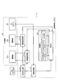
- FIG. 1 is a block diagram showing an example of the configuration of a numerical control system according to a first embodiment of the present invention.
- the numerical control system 1 of the first embodiment controls the machine tool 2.
- the machine tool 2 includes a drive shaft 21 and a drive shaft 22.
- Each of the drive shaft 21 and the drive shaft 22 is composed of a motor and one or more structures connected to the motor.
- the drive shaft 22 is a spindle that imparts rotational motion to the tool
- the drive shaft 21 is a servo shaft that imparts position to the tool.
- the drive shaft 22 and the drive shaft 21 are controlled synchronously.
- the drive shaft 21 which is a servo shaft is composed of, for example, a servomotor, a coupling, a ball screw and a table
- the drive shaft 22 which is a spindle is composed of, for example, a spindle motor, a gear, a shaft and a tooling system. .
- the machine tool 2 performs cutting on a workpiece fixed on a table constituting a drive shaft 21 which is a servo shaft, by rotating a tool attached to the drive shaft 22 which is a main shaft.
- the drive shaft 21 and the drive shaft 22 are an example of a drive shaft provided in a machine tool 2 that performs processing using a tool.
- the structure of the drive shaft 21 and the drive shaft 22 is not limited to the example mentioned above.
- one drive shaft 21 which is a servo shaft is illustrated in FIG. 1, the number of servo shafts may be one or more.
- the servomotor of the drive shaft 21 and the spindle motor of the drive shaft 22 each have a rotary encoder, and outputs an encoder signal, which is a signal detected by the rotary encoder, to the numerical control system 1.
- the drive shaft 21 also detects a motor current applied to the servomotor, and outputs the detected result to the numerical control system 1 as a motor current signal.
- the drive shaft 22 detects a motor current applied to the spindle motor, and outputs the detected result to the numerical control system 1 as a motor current signal.
- the numerical control system 1 controls the drive shaft 21 and the drive shaft 22 according to an NC (Numerical Control) program which is externally supplied or held internally.
- NC Genetic Control
- the NC program includes a tool relative position command or a servo axis position command in a predetermined coordinate system, a spindle rotational speed command, and a feed speed command.
- the aforementioned coordinate system used in the NC program is called an NC program coordinate system.
- the NC program coordinate system is, for example, a coordinate system fixed to a work.
- an acceleration sensor 211 is provided on the drive shaft 21, and an acceleration sensor 221 is provided on the drive shaft 22.
- the acceleration sensor 211 detects the linear or rotational acceleration on the drive shaft 21 and outputs the detection result to the numerical control system 1 as an acceleration sensor signal.
- the acceleration sensor 221 detects the linear or rotational acceleration on the drive shaft 22 and outputs the detection result to the numerical control system 1 as an acceleration sensor signal.
- the acceleration sensor 211 and the acceleration sensor 221 may be included in the numerical control system 1.
- the acceleration sensor 211 and the acceleration sensor 221 are examples of sensors that detect the velocity or acceleration of the drive shafts 21 and 22.
- the numerical control system 1 includes a command value generation unit 11, a coordinate conversion unit 12, drive axis control units 13 and 15, disturbance estimation units 14 and 16, an identification unit 17, and a storage unit 18.
- the storage unit 18 stores a dynamics model, a processing process model, and processing conditions. The dynamics model, the processing process model and the processing conditions will be described later.
- the drive axis control units 13 and 15 and the disturbance estimation units 14 and 16 constitute a motor control device 100.
- FIG. 2 is a flowchart showing an example of an operation procedure in the numerical control system 1 of the first embodiment. The operation of the numerical control system 1 according to the first embodiment will be described with reference to FIGS. 1 and 2.
- the command value generation unit 11 analyzes the command described in the NC program, and calculates the drive axis command for each drive axis (step S1).
- the command value generation unit 11 outputs the calculated drive axis command to the drive axis control units 13 and 15. Furthermore, the command value generation unit 11 outputs, to the coordinate conversion unit 12, setting information of the NC program coordinate system, a tool relative position and a tool rotation angle in the coordinate system, and a drive axis command for each drive axis.
- the setting information of the NC program coordinate system and the tool relative position and the tool rotation angle in the coordinate system are described in the NC program.
- the drive axis control units 13 and 15 control the drive axes in accordance with the drive axis command calculated by the command value generation unit 11 (step S2). Specifically, the drive axis control unit 13 controls the motor current so that the encoder signal output from the rotary encoder of the servomotor of the drive axis 21 follows the drive axis command which is the target value. The drive axis control unit 15 controls the motor current so that the encoder signal output from the rotary encoder of the spindle motor constituting the drive axis 22 follows a drive axis command which is a target value.
- the drive axis control units 13 and 15 output a drive axis state, which is information including position command and position feedback of each drive axis, speed command and speed feedback, to the identification unit 17 described later.
- a drive axis state which is information including position command and position feedback of each drive axis, speed command and speed feedback, to the identification unit 17 described later.
- movement in the drive axis control parts 13 and 15 is a general operation according to drive axis instruction
- the disturbance estimation unit 14 and the disturbance estimation unit 16 estimate the disturbances in the drive shaft 21 and the drive shaft 22 (step S3).
- the disturbance estimation unit 14 uses the encoder signal and the motor current signal output from the drive shaft 21 and the acceleration sensor signal output from the acceleration sensor 211 to set the servo shaft to the disturbance force applied to the drive shaft 21. Estimate and output as an estimated disturbance force.
- the servo axis is regarded as a single inertial system drive system, and the disturbance force is estimated.
- the estimation method of servo axis disturbance force is not limited to the example mentioned above.
- the disturbance estimation unit 14 may calculate the final estimated disturbance force by subtracting the viscous friction force proportional to the speed of the drive shaft from the result of equation (1).
- the disturbance estimation unit 16 estimates a disturbance force applied to the main shaft as a spindle estimation disturbance force using the encoder signal and the motor current signal output from the drive shaft 22 and the acceleration sensor signal output from the acceleration sensor 221. Output.
- the disturbance estimation unit 16 estimates a disturbance force applied to the drive shaft 22 using a detection result detected by a sensor that detects the velocity or acceleration of the drive shaft 22. Specifically, the acceleration sensor signal is converted into angular acceleration, and the spindle disturbance force is estimated using the following equation (2), regarding the spindle as a single inertial system drive system.
- the method of estimating the spindle disturbance force is not limited to the above-described example.
- the disturbance estimating unit 16 may calculate, from the result of the equation (2), a product obtained by subtracting the viscous friction force proportional to the angular velocity of the drive shaft as a final estimated disturbance force.
- the disturbance estimation unit 16 may calculate and output an estimated disturbance torque instead of the estimated disturbance force.
- the coordinate conversion unit 12 is based on the setting information of the NC program coordinate system output from the command value generation unit 11 and the tool relative position and the tool rotation angle in the NC program coordinate system.
- the servo axis estimation disturbance force calculated by the disturbance estimation unit 14 and the spindle estimation disturbance force calculated by the disturbance estimation unit 16 are coordinate-converted to the tool reference coordinate system and output (step S4). That is, the coordinate conversion unit 12 acquires a disturbance force or a disturbance torque applied to the drive shafts 21 and 22, and coordinate-converts the disturbance force or the disturbance torque to the tool reference coordinate system and outputs the coordinate.
- the coordinate conversion unit 12 acquires the disturbance force or the disturbance force vector of each drive axis from the disturbance estimation units 14 and 16.
- the tool reference coordinate system is a coordinate system including a tool axis direction and two directions in a plane perpendicular to the direction.
- the tool axis direction coincides with the Z axis, and a plane perpendicular to the tool axis direction.
- It is a coordinate system based on the tool which makes the tool advancing direction in an inside the X-axis, and makes a direction perpendicular
- the tool reference coordinate system is a coordinate system that translates along with the translational movement of the tool, but is a coordinate system that does not consider the rotation along with the rotation of the tool.
- the tool reference coordinate system is not limited to the example described above, and may be a coordinate system including the tool axis direction and two directions in a plane perpendicular to the direction.
- the spindle disturbance force is different from the servo axis disturbance force, and is the amount by which the direction of the force changes depending on the tool rotation angle. For this reason, coordinate conversion of the spindle disturbance force is performed for each tool rotation angle.
- FIG. 3 is a diagram showing the relationship between coordinate systems in the first embodiment.
- the work 32 is placed on the table 31 constituting the drive shaft 21, and the tooling system 34 constituting the drive shaft 22 holds the tool 33.
- the table 31 is driven by a servomotor (not shown), and the tooling system 34 is driven by a spindle motor (not shown).
- Coordinate system XYZ is a tool reference coordinate system
- coordinate system X'-Y'-Z ' is an NC program coordinate system
- coordinate system X' '-Y' '-Z' 'is a machine coordinate It is a system.
- the direction 35 indicates the direction of relative displacement of the tip of the work 32 with respect to the table 31.
- the coordinate conversion unit 12 sets a tool reference coordinate system XYZ using setting information of the NC program coordinate system and tool relative position information. Further, the coordinate conversion unit 12 coordinate-converts the estimated disturbance force of the servo axis calculated by the disturbance estimation unit 14 into the estimated disturbance force in the tool reference coordinate system XYZ and outputs the coordinate to the identification unit 17. The coordinate conversion unit 12 can also coordinate-convert the estimated disturbance force of the spindle calculated by the disturbance estimation unit 16 into an estimated disturbance force in the tool reference coordinate system and output it to the identification unit 17.
- the coordinate conversion unit 12 Since the estimated disturbance force of the servo axis and the estimated disturbance force of the main axis respectively include components in the X direction and Y direction in the tool reference coordinate system, the coordinate conversion unit 12 performs the following processing for the X direction and Y direction.
- the estimated disturbance force to be output to the identification unit 17 can also be determined.
- the coordinate conversion unit 12 obtains an average value for each component in the X direction and the Y direction, and adds the Z axis component of the servo axis estimation disturbance force to the identification unit 17 as a final estimation disturbance force.
- a drive axis to be adopted as a final estimated disturbance force may be set in advance for each machining path, and the estimated disturbance force corresponding to the drive axis may be coordinate-converted and output. Furthermore, as another example, an average value of each direction of X axis component and Y axis component of servo axis estimation disturbance force and spindle estimation disturbance force is calculated, and the average value of these is adopted as a final estimation disturbance force.
- the coordinate conversion unit 12 presets the lower limit value for determination and the upper limit value for determination on the X axis component and the Y axis component of the servo axis estimation disturbance force and the spindle estimation disturbance force,
- An X axis component or a Y axis component of a servo axis estimation disturbance force or a spindle estimation disturbance force which is equal to or higher than the determination lower limit value and lower than the determination upper limit value may be adopted as a final estimation disturbance force.
- the coordinate conversion unit 12 selects a combination having mutually independent directions from among the acquired disturbance force or disturbance torque.
- reliability may be set for each drive axis, and a drive axis with high reliability may be adopted for coordinate conversion.
- the estimation accuracy of a multi-inertia drive shaft is lower than that of a single-inertia drive shaft.
- a drive shaft having a simple structure can be preferentially adopted.
- the setting method of the reliability by setting the reliability of the drive shaft close to the processing part high and setting the reliability of the drive shaft far from the processing part low, the influence of the cutting force generated in the processing part It is possible to preferentially adopt a drive shaft that is easy to receive.
- the setting method of the reliability by setting the value higher than 0 when the drive axis is in operation, and setting it as 0 when in standstill, the drive axis in operation is preferentially adopted. can do.
- the above setting methods of reliability can also be used in combination.
- the setting method of reliability is not limited above.
- the identifying unit 17 calculates parameters such as dynamic characteristic parameters for determining the characteristics of the dynamics model and machining process parameters for determining the characteristics of the machining process model (step S5). Specifically, identification unit 17 stores the estimated disturbance force or estimated disturbance torque output from coordinate conversion unit 12, the drive shaft state output from drive shaft control units 13 and 15, and storage unit 18.
- the dynamic characteristic parameters that determine the characteristics of the dynamics model and the machining process parameters that determine the characteristics of the machining process model are calculated using the machining conditions, the dynamics model, and the machining process model.
- the dynamic characteristic parameter is a parameter that determines the characteristic of a dynamics model to be described later, and is, for example, a damping coefficient, a natural frequency, a mass, or a vibration mode vector.
- the machining process parameters are parameters for determining the characteristics of a machining process model described later, and are, for example, a specific cutting resistance, an edge force, a tool eccentricity amount, and a tool wear width.
- the processing conditions include feed amount per blade, tool diameter, number of tool blades, tool twist angle, tool axial direction cut amount, tool radial direction cut amount, work material shape, up cut or down Information including a processing mode representing a cut is set.
- FIG. 4 is a schematic diagram showing how a disturbance force is transmitted to the table 31 when the workpiece 32 fixed to the table 31 vibrates due to the cutting force in the first embodiment.
- FIG. 4 similarly to the example shown in FIG. 3, a configuration example in which the work 32 is placed on the table 31 configuring the drive shaft 21 and the tooling system 34 configuring the drive shaft 22 holds the tool 33 It is assumed. Further, in FIG.
- the relative displacement 36 indicates the relative displacement of the tip of the workpiece 32 relative to the table 31 in the vibration mode vector direction
- the cutting force 37 indicates the cutting force on the workpiece 32
- the disturbance force 38 is a disturbance transmitted to the table 31 It shows the power.
- the relationship between the cutting force 37, the disturbance force 38, and the relative displacement 36 at this time can be expressed by the following equation (3).
- the dynamics model shown in equation (3) calculates the disturbance force transmitted to the drive shaft through the machine structure including the tool or work when the cutting force is generated, and each time through the machine structure when the cutting force is generated. It is a mathematical model for calculating the positional deviation which arises in a drive axis.
- the dynamics model shown in equation (3) is a model in which the work 32 on the table 31 is described as a vibration system with one degree of freedom, but the dynamics model is not limited to the above example. For example, it may be described as a multi-degree-of-freedom vibration system including the fixing portion for fixing the work 32 and the table 31. Furthermore, a dynamics model may be set for a tool side structure including the tool 33, the tooling system 34 and the spindle motor. Furthermore, a dynamics model may be set as a vibration system in which the work 32 side structure and the tool 33 side structure are combined.
- the machining process model is a mathematical model that describes the cutting process between the tool 33 and the workpiece 32.
- An example of the processing process model is represented by the following equation (4).
- the above equation (4) is a mathematical expression for calculating the cutting force that the tool applies to the workpiece from the cutting thickness corresponding to the tool rotation angle at each time.
- the cutting thickness refers to a thickness at which the work 32 is cut when the tool cutting edge which is the cutting edge of the tool 33 passes through the work 32.
- the cutting force is calculated as a value greater than or equal to zero when the cutting edge of the tool contacts the work 32, as shown in FIGS. 5 and 6, but when the cutting edge of the tool is not contacting the work 32, Is calculated as zero.
- FIG. 5 is a view showing an example of the rotation angle of the tool 33 in which the tool tip contacts the workpiece 32.
- FIG. 6 is a view showing an example of the rotation angle of the tool 33 in which the tool tip does not contact the workpiece 32. That is, it is determined based on the positional deviation for each rotation angle or time of the tool 33 whether or not it contacts the workpiece 32, and if the tool tip contacts the workpiece 32, the cutting thickness is calculated and the tool tip is the workpiece If 32 are not in contact, the cut thickness is calculated as zero.
- the cutting force in the three directions can be calculated by performing the calculation shown in the equation (4) for the three directions of the tangential direction, radial direction and axial direction of the tool.
- the cutting force in the tool reference coordinate system is calculated by performing coordinate conversion by multiplying the cutting force having the components in the three directions by the rotation matrix according to the tool rotation angle. Equation (5) shows an example of coordinate conversion.
- the final cutting force is calculated by executing the calculations shown in the equations (4) and (5) as many as the number of the cutting edges of the tool.
- the machining process model shown in the equation (4) calculates the cutting thickness based on the relative position between the cutting edge of the tool and the workpiece to be machined by the tool and the tool rotation angle, and based on the cutting thickness It is a mathematical model for calculating the cutting force generated between the tool and the work.
- the cutting thickness in Equation (4) can be calculated by Equation (6) using the feed amount per blade and the tool rotation angle.
- the cut thickness can also be calculated using equation (7).
- Formula (7) adds the amount of fluctuation calculated from the difference between the current tool displacement and the pre-machining surface to Formula (6), and also adds the amount of correction according to each tool cutting edge. It is a calculation formula of In the calculation shown in the equation (7), of the displacement amount generated at the current tool edge and the displacement amount generated at the one or more previous tool edge, the displacement amount that affected the machining surface shape and the current tool edge The cut-off thickness is corrected by the difference from the amount of displacement that has occurred. That is, a tool whose cutting thickness has affected the machining surface shape among the path generated by the current tool edge involved in cutting and the tool edge of one or more blades before the current tool edge. It is calculated based on the difference with the trajectory of the cutting edge.
- the tool blade edge of one or more blades before is a tool blade edge involved in cutting at a time before the time based on the tool blade edge involved in cutting.
- the tool edge one blade before is the first blade before 180 degrees rotation and 360 two blades ago.
- the cutting edge of the tool three blades before is the first blade before rotation by 540 degrees.
- the cutting thickness is corrected by the correction amount according to the tool cutting edge number which is a number indicating the tool cutting edge and the tool rotation angle.
- a correction amount is introduced to correct the change in the thickness of the cut due to cutting with a different turning radius for each cutting edge of the tool.
- the following can be mentioned. For example, when wear or chipping occurs on a specific cutting edge, the turning radius of the tool cutting edge becomes shorter than that of other tool cutting edges, and a correction amount corresponding to the wear width or chipping width is added.
- a correction amount corresponding to the mounting error is added.
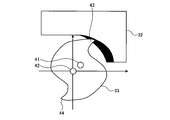
- FIG. 7 is a view showing a state of cutting at the first cutting edge when there is a displacement amount between the tool center and the spindle rotation center
- FIG. 8 is a gap between the tool center and the spindle rotation center It is a figure which shows the mode of cutting in the 2nd blade edge when quantity has arisen.
- the first cutting edge 43 and the second cutting edge 44 are cutting edges of the tool 33.
- the tool eccentricity amount indicates the correction amount at this time. That is, the tool eccentricity amount according to the rotation angle of the tool is added to or subtracted from the cut thickness.
- the case in which the cutting thickness is corrected by the correction amount is not limited to the above case, and the correction amount may be appropriately changed in accordance with the phenomenon occurring in the cutting edge.
- the processing process model is not limited to the equation (4).
- the value of the specific cutting resistance may be changed between the high speed where the cutting speed is equal to or higher than the threshold and the low speed where the cutting speed is less than the threshold.
- it may be a model in which an edge force component is added as a constant term to the right side of the equation (4).
- it is good also as a model which added process damping power to the right-hand side of Formula (4).
- the process damping force is a force generated when the flank of the tool tip contacts the workpiece.
- a machining process model for a tool with a twist angle may be used.
- the tool is divided in the axial direction into a tool with a small thickness, the cutting force in each of the divided small thickness tools is calculated, the cutting force is integrated in the tool axis direction, and the final cutting force is obtained.
- a model which calculates As still another example, it may be a model that calculates the cutting thickness and cutting force by finite element analysis.
- the dynamics model is the equation (3) and the machining process model is the equations (4) and (6)
- the equivalent damping coefficient and the equivalent natural frequency are identified as dynamic characteristic parameters
- the machining process parameter We will describe the process of identifying the specific cutting resistance as
- the dynamics model can be expressed in the form shown in the following equation (8) by transforming the equation (3) and performing time differentiation.
- Expression (10) is a relational expression for calculating the second derivative of the disturbance force when the dynamic characteristic parameter and the processing process parameter are given.
- the identification unit 17 substitutes the estimated disturbance force converted into the tool reference coordinate system by the coordinate conversion unit 12 into the equation (10) to calculate the dynamic characteristic parameter and the processing process parameter satisfying the equation (10).
- the equation (10) can be expressed in the matrix form of the equation (11) by arranging the time of n (n is an integer of 1 or more) points.
- the identification unit 17 can calculate the dynamic characteristic parameter and the processing process parameter by applying the method of least squares to the equation (11).
- the identification unit 17 may execute the iterative operation according to the search algorithm and search for the dynamic characteristic parameter and the processing process parameter from Expression (10) or Expression (11).
- calculation of the dynamic characteristic parameter and the processing process parameter in the identification part 17 is not limited to the calculation using Formula (10) and Formula (11).
- the parameters that can be identified are not limited to equivalent damping coefficients and equivalent natural frequencies and specific cutting forces.
- the identification unit 17 includes the dynamic characteristic including the vibration mode vector. Parameters can be identified.
- an identification unit is configured by constructing a machining process model including tool eccentricity in machining process parameters using equation (7), and setting a relational expression between dynamic characteristic parameters, machining process parameters, and disturbance force. 17 can identify processing process parameters.
- the identification unit 17 uses the disturbance force output from the coordinate conversion unit 12, the predetermined relational expression, and the processing conditions to determine the processing process parameters and processing for determining the characteristics of the processing process model. Dynamic characteristic parameters that determine the characteristics of the dynamic model of the machine 2 are calculated.
- the above-mentioned relational expression is a relational expression which defines the relation between the machining process parameter, the dynamic characteristic parameter and the disturbance force.
- the command value generation unit 11, the coordinate conversion unit 12, at least a part of the drive axis control units 13 and 15, the disturbance estimation units 14 and 16, and the identification unit 17 shown in FIG. 1 are realized by a processing circuit.
- the drive axis control units 13 and 15 may include a circuit such as an inverter that generates a motor current.
- the storage unit 18 is realized by a memory.
- the processing circuit may be a circuit including a processor or dedicated hardware.
- FIG. 9 is a diagram showing an example of the configuration of the processing circuit.
- the processing circuit 200 includes a processor 201 and a memory 202.
- the command value generation unit 11, the coordinate conversion unit 12, at least a part of the drive axis control units 13 and 15, the disturbance estimation units 14 and 16, and the identification unit 17 are realized by the processing circuit 200 shown in FIG. However, these are realized by reading and executing the program stored in the memory 202. That is, when the processing circuit 200 shown in FIG.
- the memory 202 is also used as a work area of the processor 201.
- the processor 201 is a CPU (Central Processing Unit) or the like.
- the memory 202 corresponds to, for example, a nonvolatile or volatile semiconductor memory such as a random access memory (RAM), a read only memory (ROM), or a flash memory, a magnetic disk, or the like.
- a memory for realizing the storage unit 18 may be the same as or different from the memory 202.
- the processing circuit for realizing the command value generation unit 11, the coordinate conversion unit 12, at least a part of the drive axis control units 13 and 15, the disturbance estimation units 14 and 16, and the identification unit 17 is dedicated hardware
- the processing circuit For example, it is FPGA (Field Programmable Gate Array), and ASIC (Application Specific Integrated Circuit).
- the command value generation unit 11, the coordinate conversion unit 12, at least a part of the drive axis control units 13 and 15, the disturbance estimation units 14 and 16, and the identification unit 17 are realized by combining a processing circuit including a processor and dedicated hardware. It may be done.
- the command value generation unit 11, the coordinate conversion unit 12, at least a part of the drive axis control units 13 and 15, the disturbance estimation units 14 and 16, and the identification unit 17 may be realized by a plurality of processing circuits.
- the coordinate conversion unit 12 performs coordinate conversion of the estimated disturbance force calculated by the disturbance estimation units 14 and 16 into the tool reference coordinate system, and the identification unit 17
- the dynamic characteristic parameters and the machining process parameters are identified from the relationship between the dynamic characteristic parameters, the machining process parameters and the disturbance force which are constructed based on the dynamics model, the machining process model and the machining conditions. For this reason, it is effective in the ability to calculate simultaneously the dynamic characteristic parameter and machining process parameter which are dominant parameters of cutting.
- machining process parameters are identified based on the detection result of the force sensor provided on the drive shaft and the machining process model.
- the detection result of the force sensor is a detection of a force transmitted by the cutting force through the mechanical structure, that is, a disturbance force. Therefore, in the comparative example, the mechanical dynamics do not take into consideration that the cutting force is transmitted as a disturbance force. Due to this, in the comparative example, accurate machining process parameters can not be identified.
- the disturbance estimation units 14 and 16 estimate the disturbance force
- the identification unit 17 calculates dynamic characteristic parameters and processing that are constructed based on the dynamics model, the processing process model, and the processing conditions. Dynamic characteristic parameters and machining process parameters are identified from the relationship between the process parameters and the disturbance force. Therefore, machining process parameters can be identified more accurately than in the comparative example.
- the acceleration sensor is provided on all drive axes including the main axis and the servo axis, but the number of drive axes on which the acceleration sensor is installed is not limited to the total number of drive axes.
- the acceleration sensor may be provided on the three linear servo axes and the acceleration sensor may not be provided on the main spindle, and the disturbance force vector may be calculated from the detection result of the three linear servo axes.
- an acceleration sensor is provided on the linear servo axes of two axes and no acceleration sensor is provided on the main axis, and a two-dimensional disturbance force vector on a plane formed by the servo axes is calculated from detection results by the acceleration sensor Dynamic characteristic parameters and processing process parameters may be estimated.
- a two-dimensional disturbance force vector on a plane perpendicular to the main axis is calculated from the detection result by the acceleration sensor provided on the main axis, and the servo axis direction is calculated from the detection result of the acceleration sensor provided on the servo axis parallel to the main axis
- the three-dimensional disturbance force vector may be calculated by applying the disturbance force of
- the configuration for a machine tool having three linear servo axes and a main axis is described, but the present invention is not limited to the machine tool having this axis configuration.
- the command value generation unit 11 outputs the tool relative posture in the NC program coordinate system to the coordinate conversion unit 12, and the coordinate conversion unit 12 takes servo axis estimation disturbance force and spindle estimation disturbance force in consideration of the relative posture of the tool.
- the estimated disturbance force vector can be calculated as in the first embodiment.
- the acceleration sensor is employed as means for detecting the acceleration of the drive shaft
- the physical quantity to be detected is not limited to the acceleration.
- a velocity sensor, a gyro sensor, or a laser Doppler meter may be used to employ a sensor that directly detects the velocity. That is, even if a sensor capable of detecting a physical quantity obtained by temporally differentiating a displacement amount by one or more floors is adopted, the present invention is not deviated from it.
- the numerical control system 1 described in the first embodiment may be configured of a plurality of devices.
- the motor control device 100 including the drive axis control units 13 and 15 and the disturbance estimation units 14 and 16 and the other components of the numerical control system 1 may be configured as separate devices.
- the numerical control system 1 includes a numerical control device including a command value generation unit 11, drive axis control units 13 and 15, disturbance estimation units 14 and 16, and a coordinate conversion unit 12, an identification unit 17 and a storage unit 18. It may be configured with the provided industrial computer.
- the industrial computer may be installed near the machine tool 2 or may be installed at a distance from the machine tool 2. Further, the industrial computer may be connected to a plurality of machine tools 2.
- the industrial computer may be externally connected through a public line such as a wired or wireless Internet line.
- a public line such as a wired or wireless Internet line.
- the numerical control system 1 includes a plurality of devices, at least a part of the command value generation unit 11, the coordinate conversion unit 12, the drive axis control units 13 and 15, the disturbance estimation units 14 and 16, and the identification unit 17
- the present invention is realized by a processing circuit mounted on a device to be mounted.
- These processing circuits may be processing circuits including a processor, may be dedicated hardware, or a combination of processing circuits including a processor and dedicated hardware, similarly to the processing circuits described above. It may be.
- a machine tool that performs milling by rotating a tool is described, but the present invention is also applicable to a machine tool that performs turning by rotating a workpiece.
- FIG. 10 is a view showing an example of the configuration of a numerical control system 1a according to a second embodiment of the present invention.
- the numerical control system 1a of the second embodiment controls the machine tool 2a.
- the machine tool 2a includes a drive shaft 21a, which is a servo shaft, and a drive shaft 22a, which is a main shaft.
- the drive shaft 21a and the drive shaft 22a are the same as the drive shaft 21 and the drive shaft 22 of the first embodiment, respectively, except that the acceleration sensor is not provided.
- a force sensor 23 is provided on the machine tool 2a.
- the force sensor 23 is installed, for example, on the table 331 or inside the table 31 shown in FIG.
- the installation location of the force sensor 23 is not limited to this example, and the force sensor 23 may be installed so as to detect the force applied to each drive shaft.
- the force sensor 23 is an example of a sensor that detects the force or torque applied to the drive shafts 21a and 22a.
- the disturbance force is estimated using the result detected by the acceleration sensor, the encoder signal, and the motor current signal.
- the numerical value can be obtained by using the force sensor 23.
- the numerical control system 1a of the second embodiment has a configuration in which the disturbance estimation units 14 and 16 are removed from the numerical control system 1 of the first embodiment, and the detection result by the force sensor 23 is input to the coordinate conversion unit 12.
- the components having the same functions as those in the first embodiment are given the same reference numerals as those in the first embodiment, and duplicate explanations are omitted.
- points different from the first embodiment will be described.
- the coordinate conversion unit 12 performs the coordinate conversion as in the first embodiment, using the detection result by the force sensor 23 instead of the servo axis estimation disturbance force and the spindle estimation disturbance force input from the disturbance estimation units 14 and 16, respectively. , And outputs the disturbance force after coordinate conversion to the identification unit 17 in the same manner as the estimated disturbance force of the first embodiment. That is, in the second embodiment, the coordinate conversion unit 12 acquires the disturbance force from the detection result detected by the sensor that detects the force or torque applied to the drive shafts 21a and 22a. When this sensor is a sensor that detects a torque, the coordinate conversion unit 12 performs coordinate conversion after converting the torque into a force.
- the identification unit 17 calculates dynamic characteristic parameters and processing process parameters as in the first embodiment.
- the operation of the numerical control system 1a other than that described above is the same as the operation of the numerical control system 1a of the first embodiment.
- the coordinate conversion unit 12 may coordinately convert the detected torque and output it to the identification unit 17, and the identification unit 17 may calculate the dynamic characteristic parameter and the processing process parameter using the torque converted coordinate.
- the dynamic characteristic parameter and the processing process parameter are calculated using the force sensor 23 without using the acceleration sensor and the disturbance estimating units 14 and 16 as in the first embodiment. Can. Thereby, the same effect as that of the first embodiment can be obtained.
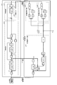
- FIG. 11 is a block diagram showing a configuration example of a disturbance estimation unit according to the third embodiment of the present invention.
- the numerical control system according to the third embodiment is the same as the numerical control system 1 according to the first embodiment except that a disturbance estimation unit 14 a is provided instead of the disturbance estimation unit 14 according to the first embodiment.
- a disturbance estimation unit 14 a is provided instead of the disturbance estimation unit 14 according to the first embodiment.
- the disturbance estimation unit 14 calculates the disturbance force in the high frequency band that can not be estimated only by the drive axis signal by acquiring the drive axis signal and the acceleration sensor signal from the drive axis 21 modeled as a single inertia system. Is realized by the aid of an acceleration sensor.
- a drive shaft constituting a machine tool is configured as a structure having a plurality of inertias, such as a motor, a ball screw, and a table.
- FIG. 12 is a view showing an example of a model of the drive shaft 21.
- FIG. 12 shows an example of a model modeled as a three-inertia system corresponding to a motor as a servomotor, a ball screw and a table when the drive shaft 21 has a servomotor, a ball screw and a table.
- T m indicates motor torque
- ⁇ m indicates motor angle
- J m and J b indicate inertia
- M t indicates mass
- D m , D b and C t indicate attenuation coefficients
- K g , K t indicates a spring constant
- R indicates a ball screw pitch
- x t indicates a position.
- m, b and t are subscripts indicating a motor, a ball screw and a table, respectively.
- the disturbance estimation unit 14a divides the structure into a plurality of parts and models, divides the acceleration sensor signal output from the acceleration sensor 211 according to the frequency band, and corresponds to each band.
- the disturbance model is estimated using the inverse model.
- the drive shaft 21 is divided into a first structure 213 and a second structure 212 for modeling. That is, the drive shaft 21 includes a first structure 213 and a second structure 212 including a motor.
- the disturbance estimation unit 14a calculates an actual drive axis output which is a resultant of forces applied to the first structure 213 based on the plurality of first structure models of the first structure 213 and the acceleration sensor signal. Further, the disturbance estimation unit 14a is a force applied by the motor to the drive shaft based on the second structure model of the second structure 212, the detection result of the motor current flowing through the motor, and the detection result of the position of the motor. Calculate a certain commanded drive axis output. Then, the disturbance estimation unit 14a estimates a disturbance force using the actual drive axis output and the command drive axis output.
- the plurality of first structure models have different frequency characteristics defined in accordance with the plurality of divided frequency bands.
- An equivalent model of the first structure 213 and the second structure 212 is illustrated in the drive shaft 21 of FIG. I ref indicates the motor current, K indicates the torque constant, v t indicates the speed of the table, and F d indicates the disturbance force.
- a t exp is an acceleration sensor signal output from the acceleration sensor 211.
- the subscript ref indicates that the reference value is calculated by the drive axis control unit 13, and the subscript exp indicates that the signal is directly detected by the acceleration sensor.
- Other characters have the same definitions as in FIG.
- An acceleration sensor 211 is provided in the first structure.
- the first structure is, for example, a table
- the second structure 212 is, for example, a mechanical structure in which a servomotor and a ball screw are combined.
- a disturbance force is applied to the first structure 213 from the outside to the drive shaft 21. Furthermore, the commanded drive shaft output resulting from the torque output of the servomotor is applied to the first structure 213, whereby the position of the first structure 213 is indirectly controlled by the drive shaft control unit 13.
- the disturbance estimation unit 14a illustrated in FIG. 11 servos the disturbance force applied to the drive shaft 21 based on the encoder signal and the motor current signal output from the drive shaft 21 and the acceleration sensor signal output from the acceleration sensor 211. Estimated as an axis estimation disturbance force.
- the disturbance estimation unit 14a includes first structure model units 143 and 144 corresponding to the first structure 213, a second structure model unit 141 corresponding to the second structure, and the combining unit 142.
- the disturbance estimation part 14a in FIG. 11 the inverse model of the corresponding structure which each part has is shown.
- LPF Low-Pass Filter
- HPF High-Pass Filter
- the letters with a hat above indicate the estimated value.
- the first structure model unit 143 and the first structure model unit 144 calculate an actual drive axis output which is a force applied to the first structure 213 based on the acceleration sensor signal.
- the first structure model unit 143 has a low pass filter
- the first structure model unit 144 has a high pass filter. These filters serve to separate the acceleration sensor signal into a first frequency band and a second frequency band at a predetermined cutoff frequency.
- the cutoff frequencies of the low pass filter and the high pass filter are, for example, upper limit values of frequencies at which the drive axis control unit 13 can control the drive axis 21.
- the first structure model unit 143 When the acceleration sensor signal separated into two bands passes through the first structure model unit 143 and the first structure model unit 144, respectively, the first structure model unit 143 outputs the actual drive axis on the low frequency side.
- the first structure model unit 144 outputs a second actual drive axis output which is an actual drive axis output on the high frequency side.
- the second structure model unit 141 uses the motor current signal and the encoder signal to calculate a command drive shaft output which is a drive force for the motor to operate the drive shaft 21.
- the combining unit 142 calculates the sum of the first actual drive axis output and the second actual drive axis output, and subtracts the command drive axis output from the calculated sum, thereby applying the disturbance force F d applied to the drive axis 21. Can be estimated.
- the drive shaft 21 is expressed as a model configured of three inertias, a spring element that couples the respective inertias, and a damper element that represents viscous friction.
- the model of the drive shaft 21 is not limited to this, and represents the drive shaft 21 as a model considering dead time due to communication of an encoder or an acceleration sensor and Coulomb friction, and the two first structure model parts corresponding thereto
- the one second structure model unit may be configured to be included in the disturbance estimation unit 14a.
- Each parameter included in the inverse model used by the disturbance estimation unit 14a can be calculated by the method described below.
- the drive axis control unit 13 gives an impulse excitation command or a random excitation command or a sine sweep excitation command to the motor of the drive shaft 21, and generates frequency response obtained from the encoder signal and the acceleration sensor signal at this time.
- the parameters can be fitted based on.
- the parameters instead of using the servomotor as the excitation source, the parameters may be fitted by exciting the servo axis using an impulse hammer from the outside.
- a test process in which the generated disturbance force is known may be performed, and the parameters may be fitted using the motor current signal, encoder signal and acceleration sensor signal output at this time.
- parameters may be calculated using finite element analysis. Furthermore, the parameters may be determined by the above combination.
- FIG. 13 is a diagram showing the estimation result of the disturbance force in the comparative example.
- the amount of state of the motor and the ball screw, that is, the first structure is estimated using the motor current signal and the encoder signal. Signals are used to estimate the state quantities of the table, and these estimation results are used to estimate the disturbance.
- the difference between the third embodiment and the comparative example is that the comparative example does not have a plurality of first structure model sections as shown in FIG. 11 but has a single first structure model section. That is, in the method of the comparative example, the mass of the table provided with the acceleration sensor is not decomposed according to the frequency band.
- the upper part of FIG. 13 shows an actual disturbance force, that is, the disturbance force actually measured using a force sensor, and the lower part of FIG. 13 shows a result estimated by the comparative example.
- the estimated value does not match the measured value by the force sensor in the high frequency band. That is, in the multi-inertia drive system represented by ball screw drive, the disturbance force can not be accurately estimated by the method of the comparative example in which the mass of the table provided with the acceleration sensor is not decomposed according to the frequency band.
- FIG. 14 is a diagram showing an example of the disturbance force estimated by the disturbance estimation unit 14a of the third embodiment.
- the upper part of FIG. 14 shows an actual disturbance force, that is, the measured disturbance force using a force sensor, and the lower part of FIG. 14 shows a result estimated by the disturbance estimation unit 14a of the third embodiment. .
- estimation results equivalent to the measurement results by the force sensor can be obtained. That is, the disturbance estimation unit 14a according to the third embodiment has an effect of being able to accurately estimate the disturbance force applied to the drive shaft in a machine tool having a multi-inertia drive system represented by ball screw drive.
- the acceleration sensor is employed as means for detecting the acceleration of the drive shaft 21, the physical quantity to be detected is not limited to the acceleration.
- a velocity sensor, a gyro sensor, or a laser Doppler meter may be used to employ a sensor that directly detects the velocity. That is, even if a sensor capable of detecting a physical quantity obtained by temporally differentiating a displacement amount by one or more floors is adopted, the present invention is not deviated from it.
- a drive shaft that can be modeled as a multi-inertia system that is, a drive shaft composed of a plurality of inertia bodies, can also be applied to servo shafts and spindles driven by other than ball screws.
- the frequency band is divided into two by providing two first structure models in the disturbance estimation unit 14a, but the number of first structure models and the number of filters are two. It is not limited. For example, three or more first structure models may be provided, and each filter may be designed to divide the frequency band by the number of first structure models.
- the disturbance estimation unit 14a may be used instead of the disturbance estimation unit 14.
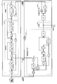
- FIG. 15 is a block diagram showing a configuration example of a disturbance estimation unit according to the fourth embodiment of the present invention.
- the numerical control system of the fourth embodiment is the same as the numerical control system 1 of the first embodiment except that a disturbance estimation unit 14 b is provided instead of the disturbance estimation unit 14 of the first embodiment.
- a disturbance estimation unit 14 b is provided instead of the disturbance estimation unit 14 of the first embodiment.
- the disturbance estimation unit 14a divides the acceleration sensor signal according to the frequency band, gives different inverse models to the respective bands, and estimates the disturbance force.
- the disturbance estimation unit 14b according to the fourth embodiment is a model in which the table provided with the acceleration sensor is divided into a first table inertia estimated by the encoder signal and the motor current signal and a second table inertia estimated by the acceleration sensor signal. Use to estimate the disturbance force.
- FIG. 16 is a diagram showing an example of modeling of the drive shaft 21 in the fourth embodiment. Each character in FIG. 16 is the same as that of the third embodiment, but those having 1 in the subscript correspond to the first table inertia model, and those having 2 in the subscript indicate the second table inertia. Corresponds to the model.
- the disturbance estimation unit 14b calculates an actual drive axis output corresponding to the first structure model based on the first structure model of the drive shaft 21 and the acceleration sensor signal. Further, the disturbance estimation unit 14b drives the motor based on the second structure model of the drive shaft 21 including the motor constituting the drive shaft 21, the detection result of the motor current flowing through the motor, and the detection result of the position of the motor.
- the command drive axis output which is a force to be applied to the axis 21 is calculated. Further, the disturbance estimation unit 14b estimates a disturbance force using the actual drive axis output and the command drive axis output.
- One of a plurality of structures constituting the drive shaft is divided into a first inertial body model and a second inertial body model for modeling, and the second structure model includes the first inertial body model;
- the structure model includes a second inertial body model.
- An example of the first inertial body model and the second inertial body model is the first table inertial model and the second table inertial model described above.
- the definition of each character in FIG. 15 is the same as that of the third embodiment.
- the drive shaft 21 is configured by a table, a servomotor, and a ball screw, as in the third embodiment.
- the model of the table is divided into two, the first table inertia and the second table inertia, the first structure 213a is a table, and the second structure 212a is a table, a motor, and a ball screw. Is modeled as a combined machine structure.
- the disturbance estimation unit 14b estimates the encoder signal and the motor current signal output from the drive shaft 21, the acceleration sensor signal output from the acceleration sensor 211, and the disturbance force applied to the drive shaft 21 as a servo axis estimation disturbance force.
- a disturbance force is applied to the drive shaft 21 from the outside to the first structure 213a. Furthermore, the commanded drive shaft output resulting from the torque output of the servomotor is applied to the first structure 213a, whereby the position of the first structure 213a is indirectly controlled by the drive shaft control unit 13.
- the disturbance estimation unit 14b includes a first structure model unit 143a corresponding to the first structure 213a, a second structure model unit 141a corresponding to the second structure 212a, and a combining unit 142a.
- the first structure model unit 143a calculates an actual drive axis output which is a resultant of forces applied to the first structure 213a based on an acceleration sensor signal.
- the first structure model unit 143a includes an LPF for noise reduction.
- the second structure model unit 141a uses a motor current signal and an encoder signal to calculate a command drive shaft output which is a drive force for the motor to operate the drive shaft 21.
- the model of the second structure 212 a is a model including a second table inertia obtained by dividing the table inertia.
- Combining section 142a by summing the command drive shaft output and the actual drive shaft output, it is possible to estimate the disturbance force F d applied to the drive shaft.
- the calculation method of each parameter included in the inverse model used in the disturbance estimation unit 14 b is the same as the calculation method of each parameter included in the inverse model used in the disturbance estimation unit 14 a of the third embodiment.
- the disturbance estimation unit 14b divides the table into a model in which the table is divided into first table inertia estimated by the drive axis signal and second table inertia estimated by the acceleration sensor signal. Use to estimate the disturbance force.
- the same effect as that of the first embodiment can be obtained, and the disturbance force can be accurately performed. Can be estimated.
- the disturbance estimation unit 14b may be used instead of the disturbance estimation unit 14.
- FIG. 17 is a block diagram showing a configuration example of a disturbance estimation unit according to the fifth embodiment of the present invention.
- the numerical control system of the fifth embodiment is the same as the numerical control system 1 of the first embodiment except that a disturbance estimation unit 14 c is provided instead of the disturbance estimation unit 14 of the first embodiment.
- a disturbance estimation unit 14 c is provided instead of the disturbance estimation unit 14 of the first embodiment.
- the first, third, and fourth embodiments are configured to estimate the disturbance force by using the encoder signal and the motor current signal together with the acceleration sensor signal.
- the motor current signal, the encoder signal and the acceleration sensor signal are signals generated from different signal sources. For this reason, the time when the disturbance estimation unit acquires each signal is not necessarily synchronized, and generally a synchronization error occurs. Therefore, the disturbance estimation unit 14c according to the fifth embodiment has a configuration in which the signal synchronization unit 145 is added to the disturbance estimation unit 14b described in the fourth embodiment, as shown in FIG.
- first correction time and second correction time are set in advance for the encoder signal and the acceleration sensor signal, respectively.
- the first correction time is a time shift amount of the encoder signal based on the motor current signal.
- the second correction time is a time shift amount of the acceleration sensor signal based on the motor current signal.
- the signal synchronization unit 145 can record an encoder signal and an acceleration sensor signal corresponding to the first and second correction times. When a motor current signal is input at a certain time, the signal synchronization unit 145 outputs an encoder signal and an acceleration sensor that differ in time by the first and second correction times from the time together with the motor current.
- the encoder signal is different from the time by the first and second correction times by interpolation or extrapolation in time.
- An acceleration sensor signal can be calculated.
- the disturbance estimating unit 14c corrects the time shift amount generated between the motor current signal, the encoder signal, and the acceleration sensor signal, and estimates the disturbance force using the signal whose time shift amount is corrected.
- the respective signals may be synchronized with one of the encoder signal or the acceleration sensor as a reference.
- a reference trigger signal for synchronization may be generated inside the signal synchronization unit 145, and each signal may be synchronized based on the reference trigger signal.
- the disturbance estimation unit 14c includes the signal synchronization unit 145 to correct the time synchronization error between the signals. Therefore, the time synchronization error can be reduced, and the disturbance force can be accurately performed. It can be estimated.
- the signal synchronization unit 145 is added to the disturbance estimation unit 14b according to the fourth embodiment, but in the same manner, the disturbance estimation unit 14 according to the first embodiment and the disturbance estimation unit 14a according to the third embodiment By adding the synchronization unit 145, the time synchronization error can be similarly corrected.
- FIG. 18 is a block diagram showing a configuration example of a numerical control system according to a sixth embodiment of the present invention.
- the numerical control system 1b of the sixth embodiment adds the simulation unit 19 to the numerical control system 1 of the first embodiment, and replaces the command value generation unit 11 and the identification unit 17 with the command value generation unit 11a and the identification unit 17a.
- the numerical control system 1b of the sixth embodiment is the same as the numerical control system 1 of the first embodiment except for these.
- the components having the same functions as those in the first embodiment are given the same reference numerals as those in the first embodiment, and duplicate explanations are omitted. The differences from the first embodiment will be mainly described below.
- the NC program describes an identification command in addition to the relative position command of the tool in the NC program coordinate system or the position command of each servo axis, the spindle rotational speed command, and the feed speed command.
- the identification command is a command for causing the identification unit 17a to start identification processing of dynamic characteristic parameters and processing process parameters.
- the command value generation unit 11a analyzes the command described in the NC program, and generates drive axis commands respectively corresponding to the drive shafts 21 and 22 as in the first embodiment, and the corresponding drive axis control units 13 and 15 Output to each.
- the command value generation unit 11a outputs an identification command to the identification unit 17a when the analyzed command includes an identification command. That is, when the NC program includes a command instructing the identification unit 17a to perform identification, the command value generation unit 11a instructs the identification unit 17a to calculate the machining process parameter and the dynamic characteristic parameter. . Furthermore, the command value generation unit 11a corrects the drive axis command according to the reproduction result of the mechanical dynamics and the machining process described later output from the simulation unit 19.
- the identification unit 17a calculates dynamic characteristic parameters and processing process parameters by the same method as the method described in the first embodiment, and the calculation results are obtained. Output to the simulation unit 19. Further, the identification unit 17a compares the estimated disturbance force output from the coordinate conversion unit 12 with the reproduction disturbance force output from the simulation unit 19.
- the estimated disturbance force is the cutting force calculated by the disturbance estimation unit and coordinate-converted by the coordinate conversion unit
- the reproduction disturbance force is the cutting force calculated by the simulation unit 19. If the difference between the estimated disturbance force and the reproduced disturbance force is larger than the threshold value, the identification unit 17a determines that there is a change in the processing state, and executes the identification process again.
- the identification unit 17a calculates the difference between the disturbance force output from the coordinate conversion unit 12 and the disturbance force reproduced by the simulation unit 19, and when the difference is larger than the threshold value, the machining process parameters and the dynamic characteristic parameters are calculated. calculate.
- the identifying unit 17a calculates a norm for each cutting force and compares the norms to obtain a difference between the estimated disturbance force and the reproduced disturbance force. Can be calculated.
- the difference between the estimated disturbance force and the reproduction disturbance force in a specific one direction such as the tool traveling direction may be calculated, and this difference may be compared with the threshold value.
- the simulation unit 19 calculates the drive axis position based on the encoder signals output from the drive axes 21 and 22, and uses the dynamics model, the processing process model and the processing conditions to calculate the structure around the tool and the work. Reproduce the vibration and the machining process between the tool and the workpiece.
- the reproduction of the vibration of the structure around the tool and the work is performed as follows.
- the simulation unit 19 uses the dynamics model to calculate the relative displacement generated in the structure when the cutting force acts on one or both of the workpiece side structure and the tool side structure.
- the simulation unit 19 calculates the positional deviation of the tool from the calculated relative displacement in the structure and the positions of the drive shafts 21 and 22, and calculates the disturbance force applied to the drive shafts 21 and 22.
- the positional deviation of the tool is the difference between the position of the tool in a state in which no cutting force is generated in the tool and the position of the tool in a state in which a cutting force is generated in the tool.
- the reproduction of the machining process is performed as follows.
- the simulation unit 19 calculates the trajectory of the cutting edge of the tool from the positional deviation of the tool with respect to the workpiece and the rotation angle of the tool using the processing conditions and the processing process model.
- the cutting thickness is calculated from the trajectory of the tool edge, and the cutting force corresponding to the cutting thickness is calculated.
- the cutting force calculated here is output to the identification unit 17a.
- the cutting force used in the dynamics model is calculated by the machining process model, and the positional deviation of the tool used in the machining process is calculated by the dynamics model. Therefore, the simulation unit 19 can reproduce the momentary mechanical dynamics and the machining process simultaneously by alternately repeating the calculation using the dynamics model and the calculation using the machining process model. In other words, the simulation unit 19 reproduces the cutting force generated between the tool and the work based on the motor current signal, the encoder signal and the processing conditions, and the processing process model, and the cutting force is based on the dynamics model. It is possible to reproduce the disturbance force generated at each drive axis when it occurs and the relative position deviation of the tool and the work.
- the command value generation unit 11 a adds the movement amount of the deviation to the drive axis command of each servo axis using the position deviation of the tool reproduced by the simulation unit 19. By this correction, it is possible to reduce the dimensional error caused by the positional deviation of the tool.
- the command value generation unit 11a compares the cutting thicknesses of the respective tool edges reproduced by the simulation unit 19 and determines that the maximum values of the cutting thicknesses generated by the respective cutting edges are equal. The feed amount per turn or each servo axis position may be corrected. This correction can reduce the vibration of the cutting edge of the tool caused by the change in the cutting thickness.
- the command value generation unit 11a uses the cutting force reproduced by the simulation unit 19 to calculate the maximum value or the average value within a fixed time, and the calculation result is a predetermined cutting force. When the upper limit is exceeded, the feed amount per blade may be reduced. By this correction, the cutting force can be limited to the cutting force upper limit value or less. Tool breakage due to excess cutting force can be avoided.
- the command value generation unit 11a compares the cutting forces generated by the cutting edges during one rotation of the tool using the cutting force reproduced by the simulation unit 19, and the cutting forces generated by the cutting edges
- the feed amount per spindle or the spindle rotational speed may be corrected so that the maximum values of x and y become equal.
- the command value generation unit 11a calculates the machined surface roughness from the trajectory of the tool blade tip reproduced by the simulation unit 19, and the machined surface roughness is previously determined with the machined surface roughness upper limit value. If it exceeds, the feed amount per blade may be reduced. By this correction, a finish machined surface is formed in which the machined surface roughness is equal to or less than the machined surface roughness upper limit.
- a plurality of processes may be combined among the correction processes described above.
- the numerical control system 1b identifies the dynamic characteristic parameter and the processing process parameter at the timing described in the NC program or at the timing when it is determined that the processing state has changed.
- the mechanical dynamics and the machining process are reproduced, and the command value generation unit corrects the drive axis command based on the reproduction result. For this reason, the following effects are achieved.
- the numerical control system 1b can identify the dynamic characteristic parameter and the processing process parameter at the timing designated by the NC program. Therefore, even if the machining state changes during the same NC program, the dynamic characteristic parameter and the machining process parameter can be identified at the timing described in the NC program.
- the identification unit 17a can verify the dynamic characteristic parameters and the processing process parameters that determine the characteristics of the dynamics model and the processing process model. Therefore, when the machine dynamics or the processing process changes, the identification process can be performed each time so that the simulation unit can reproduce the disturbance force correctly as compared to the estimated disturbance force. Furthermore, the simulation unit 19 can change the machining process in real time by reproducing the mechanical dynamics and the machining process.
- the numerical control system 1b described in the sixth embodiment executes the identification process also when the machine dynamics or the machining process changes at a timing not instructed by the NC program. be able to.
- the command value generation unit By executing a simulation using the dynamics model and processing process model whose characteristics are determined by the dynamic characteristic parameters and processing process parameters obtained from this identification process, the command value generation unit generates simulation results for each drive axis. Correction based on can be added.
- FIG. 19 is a block diagram showing another configuration example of the numerical control system of the sixth embodiment.
- the feedback position indicated by the encoder signal that can be obtained from the drive shafts 21 and 22 is input to the simulation unit 19.
- the command position generated in each of the control units 13 and 15 is input to the simulation unit 19.
- the simulation unit 19 carries out a simulation in the same manner as the simulation unit 19 of the configuration example shown in FIG. 18 using the command position generated inside each of the drive axis control units 13 and 15 instead of the feedback position.
- the operation in the configuration example shown in FIG. 19 is the same as the operation in the configuration example shown in FIG. 18 except the points described above.
- the components having the functions shown in FIG. 18 are denoted by the same reference numerals. With the configuration shown in FIG. 19, the same effects as those of the numerical control system 1b shown in FIG. 18 can be obtained.
- FIG. 20 is a block diagram showing a configuration example of a numerical control system according to a seventh embodiment of the present invention.
- the numerical control system 1c of the seventh embodiment adds a simulation unit 19 to the numerical control system 1a of the second embodiment.
- the numerical control system 1c of the seventh embodiment is the same as the numerical control system 1a of the second embodiment except for these.
- the components having the same functions as those in the second embodiment and the sixth embodiment are denoted by the same reference numerals as those in the second embodiment, and the redundant description will be omitted.
- the dynamic characteristic parameter and the processing process parameter are calculated in the same manner as in the first embodiment using the force sensor 23 without using the acceleration sensor and the disturbance estimating units 14 and 16. Furthermore, the dynamic characteristic parameters and processing process parameters are identified at the timing described in the NC program or at the timing when it is determined that the processing state has changed, and the mechanical dynamics and processing process are further reproduced by simulation, and the command based on the reproduction result
- the value generation unit corrects the drive axis command. Thereby, the same effect as that of the sixth embodiment can be achieved.
- FIG. 21 is a block diagram showing another configuration example of the numerical control system of the seventh embodiment.
- the feedback position indicated by the encoder signal that can be obtained from the drive shafts 21a and 22a is input to the simulation unit 19.
- the command position generated in each of the control units 13 and 15 is input to the simulation unit 19.
- the simulation unit 19 carries out a simulation in the same manner as the simulation unit 19 of the configuration example shown in FIG. 20, using the command position generated inside each of the drive axis control units 13 and 15 instead of the feedback position.
- the operation in the configuration example shown in FIG. 21 is the same as the operation in the configuration example shown in FIG. 20 except for the points described above.
- the components having the functions shown in FIG. 20 are denoted by the same reference numerals. Even with the configuration shown in FIG. 21, the same effects as those of the numerical control system 1c shown in FIG. 20 can be obtained.
- the configuration shown in the above embodiment shows an example of the contents of the present invention, and can be combined with another known technique, and one of the configurations is possible within the scope of the present invention. Parts can be omitted or changed.
Landscapes
- Engineering & Computer Science (AREA)
- Human Computer Interaction (AREA)
- Manufacturing & Machinery (AREA)
- Physics & Mathematics (AREA)
- General Physics & Mathematics (AREA)
- Automation & Control Theory (AREA)
- Numerical Control (AREA)
- Feedback Control In General (AREA)
Abstract
La présente invention concerne un système de contrôle numérique (1) qui comprend : une unité de conversion de coordonnées (12) qui contrôle des arbres d'entraînement (21, 22) fournis à une machine-outil (2) qui effectue un usinage à l'aide d'un outil conformément à un programme de contrôle numérique, qui acquiert la force de perturbation ou le couple de perturbation appliqué aux arbres d'entraînement (21, 22), qui convertit la force de perturbation ou le couple de perturbation en un système de coordonnées de base d'outil, et qui délivre le résultat ; et une unité d'identification (17) qui calcule un paramètre de processus d'usinage qui détermine les caractéristiques d'un modèle de processus d'usinage et d'un paramètre de caractéristiques de dynamique qui détermine les caractéristiques d'un modèle de dynamique de la machine-outil (2), les calculs étant effectués à l'aide de la force de perturbation ou du couple de perturbation délivré par l'unité de conversion de coordonnées (12), de l'état d'arbre d'entraînement, d'une expression relationnelle prédéfinie et de conditions d'usinage. L'expression relationnelle définit la relation du paramètre de processus d'usinage, du paramètre de caractéristiques de dynamique, et de la force de perturbation ou du couple de perturbation.
Priority Applications (6)
| Application Number | Priority Date | Filing Date | Title |
|---|---|---|---|
| PCT/JP2017/031261 WO2019043852A1 (fr) | 2017-08-30 | 2017-08-30 | Système de contrôle numérique et contrôleur de moteur |
| CN201780094222.6A CN111052015B (zh) | 2017-08-30 | 2017-08-30 | 数控系统及电动机控制装置 |
| US16/638,751 US11630437B2 (en) | 2017-08-30 | 2017-08-30 | Numerical control system and motor drive controller |
| DE112017007995.0T DE112017007995B4 (de) | 2017-08-30 | 2017-08-30 | Numerisches steuersystem und motorantriebssteuerung |
| JP2019538836A JP6804657B2 (ja) | 2017-08-30 | 2017-08-30 | 数値制御システムおよびモータ制御装置 |
| US18/091,389 US11733673B2 (en) | 2017-08-30 | 2022-12-30 | Numerical control system and motor drive controller |
Applications Claiming Priority (1)
| Application Number | Priority Date | Filing Date | Title |
|---|---|---|---|
| PCT/JP2017/031261 WO2019043852A1 (fr) | 2017-08-30 | 2017-08-30 | Système de contrôle numérique et contrôleur de moteur |
Related Child Applications (2)
| Application Number | Title | Priority Date | Filing Date |
|---|---|---|---|
| US16/638,751 A-371-Of-International US11630437B2 (en) | 2017-08-30 | 2017-08-30 | Numerical control system and motor drive controller |
| US18/091,389 Division US11733673B2 (en) | 2017-08-30 | 2022-12-30 | Numerical control system and motor drive controller |
Publications (1)
| Publication Number | Publication Date |
|---|---|
| WO2019043852A1 true WO2019043852A1 (fr) | 2019-03-07 |
Family
ID=65527441
Family Applications (1)
| Application Number | Title | Priority Date | Filing Date |
|---|---|---|---|
| PCT/JP2017/031261 Ceased WO2019043852A1 (fr) | 2017-08-30 | 2017-08-30 | Système de contrôle numérique et contrôleur de moteur |
Country Status (5)
| Country | Link |
|---|---|
| US (2) | US11630437B2 (fr) |
| JP (1) | JP6804657B2 (fr) |
| CN (1) | CN111052015B (fr) |
| DE (1) | DE112017007995B4 (fr) |
| WO (1) | WO2019043852A1 (fr) |
Cited By (8)
| Publication number | Priority date | Publication date | Assignee | Title |
|---|---|---|---|---|
| JP2021056835A (ja) * | 2019-09-30 | 2021-04-08 | ファナック株式会社 | シミュレーション装置 |
| CN113874798A (zh) * | 2019-05-23 | 2021-12-31 | 三菱电机株式会社 | 数控装置 |
| JP7166488B1 (ja) * | 2021-09-30 | 2022-11-07 | 三菱電機株式会社 | 数値制御装置、加工システム、数値制御方法および加工方法 |
| JP7199616B1 (ja) * | 2022-05-18 | 2023-01-05 | 三菱電機株式会社 | 加工結果評価装置、加工結果評価方法、加工条件決定装置、および加工条件決定方法 |
| CN115698886A (zh) * | 2020-06-23 | 2023-02-03 | 吉第联合股份公司 | 用于制造或包装消费品的自动机器的预测性维护的方法 |
| JP7224541B1 (ja) * | 2021-09-30 | 2023-02-17 | 三菱電機株式会社 | 数値制御装置、加工システム、数値制御方法および加工方法 |
| CN116659914A (zh) * | 2023-06-01 | 2023-08-29 | 南京航空航天大学 | 一种滚珠丝杠驱动系统外部扰动力自监测方法 |
| WO2025134408A1 (fr) * | 2023-12-18 | 2025-06-26 | パナソニックIpマネジメント株式会社 | Dispositif de calcul, système de traitement, procédé de calcul et programme |
Families Citing this family (10)
| Publication number | Priority date | Publication date | Assignee | Title |
|---|---|---|---|---|
| JP7462874B2 (ja) * | 2019-09-06 | 2024-04-08 | 住友電工焼結合金株式会社 | 加工システム |
| EP3825795A1 (fr) * | 2019-11-19 | 2021-05-26 | Siemens Aktiengesellschaft | Adaptation multi-force en ligne pendant l'usinage |
| WO2021141049A1 (fr) * | 2020-01-10 | 2021-07-15 | ファナック株式会社 | Système de commande |
| CN113742880B (zh) * | 2020-05-27 | 2024-06-04 | 台达电子工业股份有限公司 | 进给系统的摩擦力预测与补偿方法及电脑可读取存储媒体 |
| JP7513725B2 (ja) | 2020-08-31 | 2024-07-09 | ファナック株式会社 | 数値制御システム及び干渉チェック支援方法 |
| US20240264577A1 (en) * | 2021-05-13 | 2024-08-08 | Sumitomo Electric Industries, Ltd. | Machining condition management system, machining control device, machining system, and machining program |
| EP4119302A1 (fr) * | 2021-07-15 | 2023-01-18 | Siemens Aktiengesellschaft | Procédé pour estimer un ou plusieurs efforts de processus associés au point central d'outil d'une machine outil |
| CN114859730A (zh) * | 2022-05-18 | 2022-08-05 | 沈阳工程学院 | 基于微铣削加工系统颤振的输出反馈动态面主动控制方法 |
| CN115438533A (zh) * | 2022-08-05 | 2022-12-06 | 东北大学 | 基于反节点振动位移的超声骨切削力的间接测量方法 |
| CN118036341B (zh) * | 2024-04-11 | 2024-07-16 | 中国长江电力股份有限公司 | 位姿依赖的在位机器人铣削加工模态耦合颤振建模方法 |
Citations (7)
| Publication number | Priority date | Publication date | Assignee | Title |
|---|---|---|---|---|
| JPH0751991A (ja) * | 1993-05-11 | 1995-02-28 | Fanuc Ltd | 工具破損防止方式 |
| JPH07129211A (ja) * | 1993-11-08 | 1995-05-19 | Fanuc Ltd | 変動負荷自動補正方式 |
| JPH08174383A (ja) * | 1994-12-21 | 1996-07-09 | Fanuc Ltd | 工具破損検出方式 |
| JPH10136682A (ja) * | 1996-10-31 | 1998-05-22 | Mitsubishi Electric Corp | トルク一定同期駆動制御装置 |
| JP2015100879A (ja) * | 2013-11-25 | 2015-06-04 | 学校法人慶應義塾 | 工作機械制御装置、工作機械制御方法、及びプログラム |
| JP2015231663A (ja) * | 2014-06-10 | 2015-12-24 | シーメンス アクチエンゲゼルシヤフトSiemens Aktiengesellschaft | 多数の要素システムを制御調節する装置および方法 |
| JP2016190276A (ja) * | 2015-03-31 | 2016-11-10 | ブラザー工業株式会社 | 数値制御装置と制御方法 |
Family Cites Families (12)
| Publication number | Priority date | Publication date | Assignee | Title |
|---|---|---|---|---|
| US5659480A (en) * | 1995-06-27 | 1997-08-19 | Industrial Service And Machine, Incorporated | Method for coordinating motion control of a multiple axis machine |
| US7212886B2 (en) * | 2002-12-12 | 2007-05-01 | Kabushiki Kaisha Yaskawa Denki | Robot control apparatus and method |
| JP3699458B2 (ja) * | 2003-05-08 | 2005-09-28 | 義昭 垣野 | 切削抵抗検出方法及び切削抵抗による加工制御方法並びに制御装置 |
| JP2007034653A (ja) * | 2005-07-27 | 2007-02-08 | Univ Kanagawa | Ncフライス盤の経路制御方法 |
| JP4487073B2 (ja) | 2006-03-03 | 2010-06-23 | 国立大学法人長岡技術科学大学 | 外力推定方法および外力推定装置 |
| JP5333905B2 (ja) * | 2008-10-22 | 2013-11-06 | 株式会社ニイガタマシンテクノ | 工作機械の制御方法及び制御装置 |
| JP5512954B2 (ja) * | 2008-10-31 | 2014-06-04 | オークマ株式会社 | 数値制御機械の位置制御装置 |
| JP5874262B2 (ja) | 2011-09-14 | 2016-03-02 | 株式会社ジェイテクト | 加工シミュレーション装置、加工シミュレーション方法、加工制御装置および加工制御方法 |
| CN102710214B (zh) * | 2012-06-11 | 2014-08-13 | 桂林电子科技大学 | 永磁同步直线电机非线性干扰的控制方法及控制系统 |
| JP6041075B2 (ja) * | 2014-10-10 | 2016-12-07 | 株式会社安川電機 | 電動機制御装置 |
| JP6366563B2 (ja) * | 2014-12-19 | 2018-08-01 | オークマ株式会社 | 工作機械における送り軸の位置制御装置 |
| US10254740B2 (en) * | 2016-09-27 | 2019-04-09 | Harmonic Drive Systems Inc. | Positioning control device for actuator provided with strain wave gearing using full-closed control with state observer |
-
2017
- 2017-08-30 WO PCT/JP2017/031261 patent/WO2019043852A1/fr not_active Ceased
- 2017-08-30 US US16/638,751 patent/US11630437B2/en active Active
- 2017-08-30 DE DE112017007995.0T patent/DE112017007995B4/de active Active
- 2017-08-30 CN CN201780094222.6A patent/CN111052015B/zh active Active
- 2017-08-30 JP JP2019538836A patent/JP6804657B2/ja active Active
-
2022
- 2022-12-30 US US18/091,389 patent/US11733673B2/en active Active
Patent Citations (7)
| Publication number | Priority date | Publication date | Assignee | Title |
|---|---|---|---|---|
| JPH0751991A (ja) * | 1993-05-11 | 1995-02-28 | Fanuc Ltd | 工具破損防止方式 |
| JPH07129211A (ja) * | 1993-11-08 | 1995-05-19 | Fanuc Ltd | 変動負荷自動補正方式 |
| JPH08174383A (ja) * | 1994-12-21 | 1996-07-09 | Fanuc Ltd | 工具破損検出方式 |
| JPH10136682A (ja) * | 1996-10-31 | 1998-05-22 | Mitsubishi Electric Corp | トルク一定同期駆動制御装置 |
| JP2015100879A (ja) * | 2013-11-25 | 2015-06-04 | 学校法人慶應義塾 | 工作機械制御装置、工作機械制御方法、及びプログラム |
| JP2015231663A (ja) * | 2014-06-10 | 2015-12-24 | シーメンス アクチエンゲゼルシヤフトSiemens Aktiengesellschaft | 多数の要素システムを制御調節する装置および方法 |
| JP2016190276A (ja) * | 2015-03-31 | 2016-11-10 | ブラザー工業株式会社 | 数値制御装置と制御方法 |
Cited By (17)
| Publication number | Priority date | Publication date | Assignee | Title |
|---|---|---|---|---|
| CN113874798A (zh) * | 2019-05-23 | 2021-12-31 | 三菱电机株式会社 | 数控装置 |
| CN113874798B (zh) * | 2019-05-23 | 2023-12-05 | 三菱电机株式会社 | 数控装置 |
| JP2021056835A (ja) * | 2019-09-30 | 2021-04-08 | ファナック株式会社 | シミュレーション装置 |
| JP7348013B2 (ja) | 2019-09-30 | 2023-09-20 | ファナック株式会社 | シミュレーション装置 |
| JP2023530858A (ja) * | 2020-06-23 | 2023-07-20 | ジー.デー ソチエタ ペル アツィオニ | 消費者向け製品を製造又は包装するための自動機械の予測保守のための方法 |
| CN115698886A (zh) * | 2020-06-23 | 2023-02-03 | 吉第联合股份公司 | 用于制造或包装消费品的自动机器的预测性维护的方法 |
| JP7728801B2 (ja) | 2020-06-23 | 2025-08-25 | ジー.デー ソチエタ ペル アツィオニ | 消費者向け製品を製造又は包装するための自動機械の予測保守のための方法 |
| CN115698886B (zh) * | 2020-06-23 | 2025-11-04 | 吉第联合股份公司 | 用于制造或包装消费品的自动机器的预测性维护的方法 |
| JP7224541B1 (ja) * | 2021-09-30 | 2023-02-17 | 三菱電機株式会社 | 数値制御装置、加工システム、数値制御方法および加工方法 |
| WO2023053400A1 (fr) * | 2021-09-30 | 2023-04-06 | 三菱電機株式会社 | Dispositif de commande numérique, système de traitement, procédé de commande numérique et procédé de traitement |
| WO2023053399A1 (fr) * | 2021-09-30 | 2023-04-06 | 三菱電機株式会社 | Dispositif de commande numérique, système d'usinage, procédé de commande numérique et procédé d'usinage |
| JP7166488B1 (ja) * | 2021-09-30 | 2022-11-07 | 三菱電機株式会社 | 数値制御装置、加工システム、数値制御方法および加工方法 |
| CN117957088A (zh) * | 2021-09-30 | 2024-04-30 | 三菱电机株式会社 | 数控装置、加工系统、数控方法及加工方法 |
| CN118019614A (zh) * | 2021-09-30 | 2024-05-10 | 三菱电机株式会社 | 数控装置、加工系统、数控方法及加工方法 |
| JP7199616B1 (ja) * | 2022-05-18 | 2023-01-05 | 三菱電機株式会社 | 加工結果評価装置、加工結果評価方法、加工条件決定装置、および加工条件決定方法 |
| CN116659914A (zh) * | 2023-06-01 | 2023-08-29 | 南京航空航天大学 | 一种滚珠丝杠驱动系统外部扰动力自监测方法 |
| WO2025134408A1 (fr) * | 2023-12-18 | 2025-06-26 | パナソニックIpマネジメント株式会社 | Dispositif de calcul, système de traitement, procédé de calcul et programme |
Also Published As
| Publication number | Publication date |
|---|---|
| US11733673B2 (en) | 2023-08-22 |
| CN111052015A (zh) | 2020-04-21 |
| DE112017007995B4 (de) | 2024-12-19 |
| US20230137542A1 (en) | 2023-05-04 |
| US11630437B2 (en) | 2023-04-18 |
| DE112017007995T5 (de) | 2020-06-18 |
| US20200333764A1 (en) | 2020-10-22 |
| CN111052015B (zh) | 2023-06-13 |
| JP6804657B2 (ja) | 2020-12-23 |
| JPWO2019043852A1 (ja) | 2020-01-16 |
Similar Documents
| Publication | Publication Date | Title |
|---|---|---|
| US11733673B2 (en) | Numerical control system and motor drive controller | |
| CN115398360B (zh) | 用于机床上的基于特征图的误差补偿的机床控制和方法 | |
| CN112904797B (zh) | 数值控制装置以及控制方法 | |
| JP6942577B2 (ja) | 工作機械の数値制御装置及び数値制御方法 | |
| Kato et al. | Analysis of circular trajectory equivalent to cone-frustum milling in five-axis machining centers using motion simulator | |
| TWI540402B (zh) | 馬達控制裝置 | |
| JP7158636B1 (ja) | 加工評価装置、加工システム、および加工評価方法 | |
| CN102368156B (zh) | 一种基于位置信息的数控机床工件加工质量在线评估方法 | |
| JP2019070916A (ja) | 切削シミュレーション方法および装置 | |
| Jiang et al. | Modeling and simulation of surface morphology abnormality of ‘S’test piece machined by five-axis CNC machine tool | |
| Bauer et al. | Analysis of industrial robot structure and milling process interaction for path manipulation | |
| Costes et al. | Surface roughness prediction in milling based on tool displacements | |
| US20160370786A1 (en) | Trajectory measuring device, numerical control device, and trajectory measuring method | |
| JP2018118362A (ja) | 工作機械および振動抑制方法 | |
| WO2022162944A1 (fr) | Dispositif de simulation, système de machine-outil, procédé de simulation et procédé d'usinage | |
| Diez et al. | Dynamic analysis of a piezoelectric system to compensate for workpiece deformations in flexible milling | |
| KR101983946B1 (ko) | 모델 지원식 오차 보상을 사용한 공작물들의 기계가공 | |
| CN114137907A (zh) | 数控机床振动幅值预测的建模方法、装置、设备及介质 | |
| JP2010186461A (ja) | 軌跡制御のための教示信号発生法、軌跡制御装置、および工作機械 | |
| Cortsen et al. | Advanced off-line simulation framework with deformation compensation for high speed machining with robot manipulators | |
| JP5334932B2 (ja) | パラメータ設定方法およびパラメータ設定装置 | |
| JP7302994B2 (ja) | ワークピース/ツール間境界における振動現象を制限するための方法 | |
| Denkena et al. | Compensation of geometrical deviations via model based-observers | |
| Sato et al. | Dynamic synchronous accuracy of translational and rotary axes | |
| Sato et al. | Active vibration suppression of NC machine tools for high-speed contouring motions |
Legal Events
| Date | Code | Title | Description |
|---|---|---|---|
| 121 | Ep: the epo has been informed by wipo that ep was designated in this application |
Ref document number: 17922955 Country of ref document: EP Kind code of ref document: A1 |
|
| ENP | Entry into the national phase |
Ref document number: 2019538836 Country of ref document: JP Kind code of ref document: A |
|
| 122 | Ep: pct application non-entry in european phase |
Ref document number: 17922955 Country of ref document: EP Kind code of ref document: A1 |