WO2019043861A1 - Dispositif et procédé de surveillance, et programme - Google Patents
Dispositif et procédé de surveillance, et programme Download PDFInfo
- Publication number
- WO2019043861A1 WO2019043861A1 PCT/JP2017/031320 JP2017031320W WO2019043861A1 WO 2019043861 A1 WO2019043861 A1 WO 2019043861A1 JP 2017031320 W JP2017031320 W JP 2017031320W WO 2019043861 A1 WO2019043861 A1 WO 2019043861A1
- Authority
- WO
- WIPO (PCT)
- Prior art keywords
- measurement data
- kneading
- unit
- kneader
- monitoring
- Prior art date
- Legal status (The legal status is an assumption and is not a legal conclusion. Google has not performed a legal analysis and makes no representation as to the accuracy of the status listed.)
- Ceased
Links
Images






Classifications
-
- B—PERFORMING OPERATIONS; TRANSPORTING
- B29—WORKING OF PLASTICS; WORKING OF SUBSTANCES IN A PLASTIC STATE IN GENERAL
- B29B—PREPARATION OR PRETREATMENT OF THE MATERIAL TO BE SHAPED; MAKING GRANULES OR PREFORMS; RECOVERY OF PLASTICS OR OTHER CONSTITUENTS OF WASTE MATERIAL CONTAINING PLASTICS
- B29B7/00—Mixing; Kneading
- B29B7/02—Mixing; Kneading non-continuous, with mechanical mixing or kneading devices, i.e. batch type
- B29B7/22—Component parts, details or accessories; Auxiliary operations
- B29B7/28—Component parts, details or accessories; Auxiliary operations for measuring, controlling or regulating, e.g. viscosity control
- B29B7/286—Component parts, details or accessories; Auxiliary operations for measuring, controlling or regulating, e.g. viscosity control measuring properties of the mixture, e.g. temperature, density
-
- B—PERFORMING OPERATIONS; TRANSPORTING
- B29—WORKING OF PLASTICS; WORKING OF SUBSTANCES IN A PLASTIC STATE IN GENERAL
- B29B—PREPARATION OR PRETREATMENT OF THE MATERIAL TO BE SHAPED; MAKING GRANULES OR PREFORMS; RECOVERY OF PLASTICS OR OTHER CONSTITUENTS OF WASTE MATERIAL CONTAINING PLASTICS
- B29B7/00—Mixing; Kneading
- B29B7/80—Component parts, details or accessories; Auxiliary operations
- B29B7/82—Heating or cooling
- B29B7/823—Temperature control
-
- B—PERFORMING OPERATIONS; TRANSPORTING
- B01—PHYSICAL OR CHEMICAL PROCESSES OR APPARATUS IN GENERAL
- B01F—MIXING, e.g. DISSOLVING, EMULSIFYING OR DISPERSING
- B01F35/00—Accessories for mixers; Auxiliary operations or auxiliary devices; Parts or details of general application
- B01F35/20—Measuring; Control or regulation
- B01F35/22—Control or regulation
- B01F35/2201—Control or regulation characterised by the type of control technique used
- B01F35/2206—Use of stored recipes for controlling the computer programs, e.g. for manipulation, handling, production or composition in mixing plants
-
- B—PERFORMING OPERATIONS; TRANSPORTING
- B01—PHYSICAL OR CHEMICAL PROCESSES OR APPARATUS IN GENERAL
- B01F—MIXING, e.g. DISSOLVING, EMULSIFYING OR DISPERSING
- B01F27/00—Mixers with rotary stirring devices in fixed receptacles; Kneaders
- B01F27/40—Mixers with rotor-rotor system, e.g. with intermeshing teeth
- B01F27/42—Mixers with rotor-rotor system, e.g. with intermeshing teeth with rotating surfaces next to each other, i.e. on substantially parallel axes
- B01F27/421—Mixers with rotor-rotor system, e.g. with intermeshing teeth with rotating surfaces next to each other, i.e. on substantially parallel axes provided with intermeshing elements
-
- B—PERFORMING OPERATIONS; TRANSPORTING
- B01—PHYSICAL OR CHEMICAL PROCESSES OR APPARATUS IN GENERAL
- B01F—MIXING, e.g. DISSOLVING, EMULSIFYING OR DISPERSING
- B01F27/00—Mixers with rotary stirring devices in fixed receptacles; Kneaders
- B01F27/60—Mixers with rotary stirring devices in fixed receptacles; Kneaders with stirrers rotating about a horizontal or inclined axis
- B01F27/72—Mixers with rotary stirring devices in fixed receptacles; Kneaders with stirrers rotating about a horizontal or inclined axis with helices or sections of helices
- B01F27/726—Mixers with rotary stirring devices in fixed receptacles; Kneaders with stirrers rotating about a horizontal or inclined axis with helices or sections of helices with two helices with opposite pitch on the same shaft; with two helices on the same axis, driven in opposite directions or at different speeds
-
- B—PERFORMING OPERATIONS; TRANSPORTING
- B01—PHYSICAL OR CHEMICAL PROCESSES OR APPARATUS IN GENERAL
- B01F—MIXING, e.g. DISSOLVING, EMULSIFYING OR DISPERSING
- B01F35/00—Accessories for mixers; Auxiliary operations or auxiliary devices; Parts or details of general application
- B01F35/20—Measuring; Control or regulation
- B01F35/21—Measuring
- B01F35/211—Measuring of the operational parameters
- B01F35/2115—Temperature
-
- B—PERFORMING OPERATIONS; TRANSPORTING
- B01—PHYSICAL OR CHEMICAL PROCESSES OR APPARATUS IN GENERAL
- B01F—MIXING, e.g. DISSOLVING, EMULSIFYING OR DISPERSING
- B01F35/00—Accessories for mixers; Auxiliary operations or auxiliary devices; Parts or details of general application
- B01F35/20—Measuring; Control or regulation
- B01F35/21—Measuring
- B01F35/212—Measuring of the driving system data, e.g. torque, speed or power data
-
- B—PERFORMING OPERATIONS; TRANSPORTING
- B01—PHYSICAL OR CHEMICAL PROCESSES OR APPARATUS IN GENERAL
- B01F—MIXING, e.g. DISSOLVING, EMULSIFYING OR DISPERSING
- B01F35/00—Accessories for mixers; Auxiliary operations or auxiliary devices; Parts or details of general application
- B01F35/71—Feed mechanisms
- B01F35/717—Feed mechanisms characterised by the means for feeding the components to the mixer
- B01F35/7173—Feed mechanisms characterised by the means for feeding the components to the mixer using gravity, e.g. from a hopper
- B01F35/71731—Feed mechanisms characterised by the means for feeding the components to the mixer using gravity, e.g. from a hopper using a hopper
-
- B—PERFORMING OPERATIONS; TRANSPORTING
- B01—PHYSICAL OR CHEMICAL PROCESSES OR APPARATUS IN GENERAL
- B01F—MIXING, e.g. DISSOLVING, EMULSIFYING OR DISPERSING
- B01F35/00—Accessories for mixers; Auxiliary operations or auxiliary devices; Parts or details of general application
- B01F35/75—Discharge mechanisms
- B01F35/754—Discharge mechanisms characterised by the means for discharging the components from the mixer
- B01F35/7547—Discharge mechanisms characterised by the means for discharging the components from the mixer using valves, gates, orifices or openings
-
- B—PERFORMING OPERATIONS; TRANSPORTING
- B01—PHYSICAL OR CHEMICAL PROCESSES OR APPARATUS IN GENERAL
- B01F—MIXING, e.g. DISSOLVING, EMULSIFYING OR DISPERSING
- B01F35/00—Accessories for mixers; Auxiliary operations or auxiliary devices; Parts or details of general application
- B01F35/90—Heating or cooling systems
- B01F35/91—Heating or cooling systems using gas or liquid injected into the material, e.g. using liquefied carbon dioxide or steam
-
- B—PERFORMING OPERATIONS; TRANSPORTING
- B29—WORKING OF PLASTICS; WORKING OF SUBSTANCES IN A PLASTIC STATE IN GENERAL
- B29B—PREPARATION OR PRETREATMENT OF THE MATERIAL TO BE SHAPED; MAKING GRANULES OR PREFORMS; RECOVERY OF PLASTICS OR OTHER CONSTITUENTS OF WASTE MATERIAL CONTAINING PLASTICS
- B29B7/00—Mixing; Kneading
- B29B7/02—Mixing; Kneading non-continuous, with mechanical mixing or kneading devices, i.e. batch type
- B29B7/06—Mixing; Kneading non-continuous, with mechanical mixing or kneading devices, i.e. batch type with movable mixing or kneading devices
- B29B7/10—Mixing; Kneading non-continuous, with mechanical mixing or kneading devices, i.e. batch type with movable mixing or kneading devices rotary
- B29B7/18—Mixing; Kneading non-continuous, with mechanical mixing or kneading devices, i.e. batch type with movable mixing or kneading devices rotary with more than one shaft
-
- B—PERFORMING OPERATIONS; TRANSPORTING
- B29—WORKING OF PLASTICS; WORKING OF SUBSTANCES IN A PLASTIC STATE IN GENERAL
- B29B—PREPARATION OR PRETREATMENT OF THE MATERIAL TO BE SHAPED; MAKING GRANULES OR PREFORMS; RECOVERY OF PLASTICS OR OTHER CONSTITUENTS OF WASTE MATERIAL CONTAINING PLASTICS
- B29B7/00—Mixing; Kneading
- B29B7/02—Mixing; Kneading non-continuous, with mechanical mixing or kneading devices, i.e. batch type
- B29B7/06—Mixing; Kneading non-continuous, with mechanical mixing or kneading devices, i.e. batch type with movable mixing or kneading devices
- B29B7/10—Mixing; Kneading non-continuous, with mechanical mixing or kneading devices, i.e. batch type with movable mixing or kneading devices rotary
- B29B7/18—Mixing; Kneading non-continuous, with mechanical mixing or kneading devices, i.e. batch type with movable mixing or kneading devices rotary with more than one shaft
- B29B7/183—Mixing; Kneading non-continuous, with mechanical mixing or kneading devices, i.e. batch type with movable mixing or kneading devices rotary with more than one shaft having a casing closely surrounding the rotors, e.g. of Banbury type
-
- B—PERFORMING OPERATIONS; TRANSPORTING
- B29—WORKING OF PLASTICS; WORKING OF SUBSTANCES IN A PLASTIC STATE IN GENERAL
- B29B—PREPARATION OR PRETREATMENT OF THE MATERIAL TO BE SHAPED; MAKING GRANULES OR PREFORMS; RECOVERY OF PLASTICS OR OTHER CONSTITUENTS OF WASTE MATERIAL CONTAINING PLASTICS
- B29B7/00—Mixing; Kneading
- B29B7/02—Mixing; Kneading non-continuous, with mechanical mixing or kneading devices, i.e. batch type
- B29B7/06—Mixing; Kneading non-continuous, with mechanical mixing or kneading devices, i.e. batch type with movable mixing or kneading devices
- B29B7/10—Mixing; Kneading non-continuous, with mechanical mixing or kneading devices, i.e. batch type with movable mixing or kneading devices rotary
- B29B7/18—Mixing; Kneading non-continuous, with mechanical mixing or kneading devices, i.e. batch type with movable mixing or kneading devices rotary with more than one shaft
- B29B7/20—Mixing; Kneading non-continuous, with mechanical mixing or kneading devices, i.e. batch type with movable mixing or kneading devices rotary with more than one shaft with intermeshing devices, e.g. screws
-
- B—PERFORMING OPERATIONS; TRANSPORTING
- B29—WORKING OF PLASTICS; WORKING OF SUBSTANCES IN A PLASTIC STATE IN GENERAL
- B29B—PREPARATION OR PRETREATMENT OF THE MATERIAL TO BE SHAPED; MAKING GRANULES OR PREFORMS; RECOVERY OF PLASTICS OR OTHER CONSTITUENTS OF WASTE MATERIAL CONTAINING PLASTICS
- B29B7/00—Mixing; Kneading
- B29B7/02—Mixing; Kneading non-continuous, with mechanical mixing or kneading devices, i.e. batch type
- B29B7/22—Component parts, details or accessories; Auxiliary operations
- B29B7/28—Component parts, details or accessories; Auxiliary operations for measuring, controlling or regulating, e.g. viscosity control
-
- B—PERFORMING OPERATIONS; TRANSPORTING
- B29—WORKING OF PLASTICS; WORKING OF SUBSTANCES IN A PLASTIC STATE IN GENERAL
- B29B—PREPARATION OR PRETREATMENT OF THE MATERIAL TO BE SHAPED; MAKING GRANULES OR PREFORMS; RECOVERY OF PLASTICS OR OTHER CONSTITUENTS OF WASTE MATERIAL CONTAINING PLASTICS
- B29B7/00—Mixing; Kneading
- B29B7/02—Mixing; Kneading non-continuous, with mechanical mixing or kneading devices, i.e. batch type
- B29B7/22—Component parts, details or accessories; Auxiliary operations
- B29B7/28—Component parts, details or accessories; Auxiliary operations for measuring, controlling or regulating, e.g. viscosity control
- B29B7/283—Component parts, details or accessories; Auxiliary operations for measuring, controlling or regulating, e.g. viscosity control measuring data of the driving system, e.g. torque, speed, power
-
- B—PERFORMING OPERATIONS; TRANSPORTING
- B29—WORKING OF PLASTICS; WORKING OF SUBSTANCES IN A PLASTIC STATE IN GENERAL
- B29B—PREPARATION OR PRETREATMENT OF THE MATERIAL TO BE SHAPED; MAKING GRANULES OR PREFORMS; RECOVERY OF PLASTICS OR OTHER CONSTITUENTS OF WASTE MATERIAL CONTAINING PLASTICS
- B29B7/00—Mixing; Kneading
- B29B7/74—Mixing; Kneading using other mixers or combinations of mixers, e.g. of dissimilar mixers ; Plant
- B29B7/7476—Systems, i.e. flow charts or diagrams; Plants
- B29B7/7495—Systems, i.e. flow charts or diagrams; Plants for mixing rubber
-
- B—PERFORMING OPERATIONS; TRANSPORTING
- B29—WORKING OF PLASTICS; WORKING OF SUBSTANCES IN A PLASTIC STATE IN GENERAL
- B29B—PREPARATION OR PRETREATMENT OF THE MATERIAL TO BE SHAPED; MAKING GRANULES OR PREFORMS; RECOVERY OF PLASTICS OR OTHER CONSTITUENTS OF WASTE MATERIAL CONTAINING PLASTICS
- B29B7/00—Mixing; Kneading
- B29B7/80—Component parts, details or accessories; Auxiliary operations
- B29B7/82—Heating or cooling
- B29B7/826—Apparatus therefor
-
- G—PHYSICS
- G01—MEASURING; TESTING
- G01M—TESTING STATIC OR DYNAMIC BALANCE OF MACHINES OR STRUCTURES; TESTING OF STRUCTURES OR APPARATUS, NOT OTHERWISE PROVIDED FOR
- G01M99/00—Subject matter not provided for in other groups of this subclass
- G01M99/005—Testing of complete machines, e.g. washing-machines or mobile phones
-
- G—PHYSICS
- G05—CONTROLLING; REGULATING
- G05B—CONTROL OR REGULATING SYSTEMS IN GENERAL; FUNCTIONAL ELEMENTS OF SUCH SYSTEMS; MONITORING OR TESTING ARRANGEMENTS FOR SUCH SYSTEMS OR ELEMENTS
- G05B15/00—Systems controlled by a computer
- G05B15/02—Systems controlled by a computer electric
-
- G—PHYSICS
- G05—CONTROLLING; REGULATING
- G05B—CONTROL OR REGULATING SYSTEMS IN GENERAL; FUNCTIONAL ELEMENTS OF SUCH SYSTEMS; MONITORING OR TESTING ARRANGEMENTS FOR SUCH SYSTEMS OR ELEMENTS
- G05B19/00—Program-control systems
- G05B19/02—Program-control systems electric
- G05B19/18—Numerical control [NC], i.e. automatically operating machines, in particular machine tools, e.g. in a manufacturing environment, so as to execute positioning, movement or co-ordinated operations by means of program data in numerical form
- G05B19/406—Numerical control [NC], i.e. automatically operating machines, in particular machine tools, e.g. in a manufacturing environment, so as to execute positioning, movement or co-ordinated operations by means of program data in numerical form characterised by monitoring or safety
-
- B—PERFORMING OPERATIONS; TRANSPORTING
- B01—PHYSICAL OR CHEMICAL PROCESSES OR APPARATUS IN GENERAL
- B01F—MIXING, e.g. DISSOLVING, EMULSIFYING OR DISPERSING
- B01F35/00—Accessories for mixers; Auxiliary operations or auxiliary devices; Parts or details of general application
- B01F35/90—Heating or cooling systems
- B01F2035/98—Cooling
Definitions
- the present invention relates to a monitoring device, a monitoring method, and a program of a kneader for kneading a rubber material.
- mixes a rubber material performs quality control of the rubber material which a kneader produces.
- a manager records and stores measurement data of monitoring targets such as temperature of rubber material, instantaneous power of kneading machine, integrated power, rotor rotational speed, position of floating weight, temperature of cooling water and the like.
- the measurement data indicates a value corresponding to the time of the measurement data to be monitored.
- the administrator confirms these measurement data and monitors the state of the kneader.
- a document related to such a technology is disclosed in Patent Document 1.
- this invention aims at providing the monitoring apparatus of the kneading machine which solves the above-mentioned subject, a monitoring method, and a program.
- the monitoring device includes a measurement data acquisition unit for acquiring measurement data of the monitoring target information obtained when the rubber material is kneaded by the kneader, the measurement data, and the measurement data And a determination unit that performs abnormality determination by comparing with reference data selected in past measurement data of the monitoring target information, and the measurement data acquisition unit is in a series of kneading operations of the rubber material in the kneading machine.
- the measurement data measured from a predetermined kneading operation start timing may be acquired in each of the series of kneading operation units.
- the reference data may be reference data indicating normal data selected in past measurement data of the monitoring target information.
- the above-mentioned monitoring apparatus may be provided with the recording part which records comparison data which shows the comparison relationship of the measurement data of the said monitoring object information, and the said reference data.
- the recording unit may record the comparison data for each type of operation mode in which the kneading machine kneads the rubber material.
- the above-mentioned monitoring apparatus may be provided with the output part which outputs the abnormal state of the said kneading machine based on the result of the said abnormality determination.
- the measurement data may be a value indicating a statistical value calculated in each of the unit measurement periods in which the unit measurement period of the monitoring target information is sequentially shifted according to the passage of time.
- the above-described monitoring device may include an abnormal time prediction unit that predicts a time when the value of the measurement data exceeds a threshold indicating an abnormality based on the result of the abnormality determination.
- the above-mentioned monitoring apparatus may be provided with the kneading machine control part which starts the suppression control which suppresses that the value of the said measurement data exceeds the threshold value which shows abnormality based on the result of the said abnormality determination.
- the monitoring method acquires measurement data of the monitoring target information obtained when the rubber material is kneaded by the kneading machine, and the past of the measurement data and the monitoring target information
- the above measurement data measured from a predetermined kneading operation start timing in a series of kneading operations of the rubber material in the kneader are compared with the reference data selected in the measurement data of It is characterized in that each unit of the kneading operation is obtained.
- the program causes the computer of the monitoring device to continuously measure data of monitoring target information measured from a predetermined kneading operation start timing in a series of kneading operations of the rubber material in the kneader. It is characterized in that it functions as measurement data acquisition means acquired in each unit of the kneading operation, and determination means for comparing the measurement data with reference data selected in the past measurement data of the monitoring target information and performing abnormality determination. I assume.
- the monitoring device can more accurately perform processing that leads the manager to early confirm the change in the state of the kneader and leads to the omission and reduction of the change in the state.
- the monitoring apparatus can suppress the deterioration and the variation of the quality of the rubber material generated by the kneading machine.
- FIG. 1 is a block diagram showing the configuration of a kneader system including the kneader control device according to the same embodiment.
- the kneader system 100 is configured by communication connection between the kneader control device 1 and the kneader 2.
- the kneading machine control device 1 according to the present embodiment internally has the function of a monitoring device that monitors the state of the kneading machine 2.
- the kneader control device 1 may be included in the kneader 2.
- the kneader control device 1 acquires measurement data indicating measured values from at least various sensors attached to the kneader 2, and uses the measurement data to monitor whether the kneader 2 is in an abnormal state. It is a computer.
- the kneader control device 1 is a computer that controls the kneader 2 and may output command signals to the kneader 2.
- the kneader 2 controls an object to be driven based on a command signal obtained from the kneader controller 1 or another controller or the like.
- the driving target is, for example, a kneading rotor that constitutes the kneading machine 2 or the like.
- the kneading machine 2 kneads rubber, silica and other additives by rotating a kneader.
- the rubber material kneaded by the kneading machine 2 is molded into a tire and other rubber products. Rubber materials include rubber raw materials, silica, carbon, coupling agents and the like.
- FIG. 2 is a schematic view of a kneader.
- the kneader 2 includes kneaders 20 and 21.
- the kneading machine 2 forms a kneading chamber 12 inside a casing 11.
- a pair of kneading rotors 20 and 21 are disposed in parallel in the kneading chamber 12.
- the pair of kneading rotors 20 and 21 rotate in opposite directions from each other by a drive source such as a motor (not shown). Further, the pair of kneading rotors 20 and 21 form wings 22 and 23 protruding outward respectively on the outer surfaces thereof.
- the wing portions 22 and 23 are formed, for example, in a spiral shape with respect to the axes 24 and 25 of the kneading rotors 20 and 21.
- the wing portions 22 and 23 are arranged to mesh with each other by the rotation of the kneading rotors 20 and 21.
- the kneading machine 2 presses the rubber material introduced into the hopper 13 into the kneading chamber 12 and the hopper 13 into which the rubber material containing the rubber raw material and the additive is introduced in communication with the kneading chamber 12 at the upper part thereof.
- a ram 14 is provided.
- the kneader 2 has attached to the bottom part the drop door 15 for taking out the knead
- the kneading machine 2 press-fits the rubber material introduced through the hopper 13 into the kneading chamber 12 by the ram 14. Next, the rubber material is kneaded by the meshing action of the kneading rotors 20 and 21 rotating in opposite directions and the shearing action generated between the kneading rotors 20 and 21 and the inner surface of the kneading chamber 12. Then, the kneading machine 2 takes out the kneaded rubber material from the kneading chamber 12 to the outside by opening the drop door 15 provided at the bottom of the kneading chamber 12 and conveys it to another process.
- the structure of the kneader 2 shown in FIG. 2 is an example, and the kneader 2 may have another structure.
- the kneader 2 may knead with a tangential rotor.
- the kneader 2 may have a mechanism in which a rubber material is introduced from a slide type opening / closing opening.
- the kneader 2 may be a kneader type kneader having a mechanism for inverting the mixing tank instead of the drop door as a discharge mechanism of the kneaded rubber material.
- the cooling water pipe is connected to each part such as a ram, a kneading chamber, and a rotor, and a flow path is formed inside each part, and the cooling water flows.
- the cooling water piping includes a first piping 26 for returning the ram cooling water for cooling the ram, a second piping 27 for cooling the kneading chamber for cooling the kneading chamber, and a third piping for returning the rotor cooling water for cooling the rotor. There are 28 and so on.
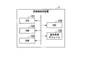
- FIG. 3 is a diagram showing a hardware configuration of the kneading machine control device according to the present embodiment.
- the kneader control device 1 includes a central processing unit (CPU) 101, a read only memory (ROM) 102, a random access memory (RAM) 103, a hard disk drive (HDD) 104, and a signal receiving module 105. It is a computer provided.
- CPU central processing unit
- ROM read only memory
- RAM random access memory
- HDD hard disk drive
- FIG. 4 is a functional block diagram of the kneading machine control device according to the present embodiment.
- the CPU 101 of the kneading machine control device 1 executes a program stored in advance by itself.
- the kneader control device 1 includes the components of the measurement data acquisition unit 111, the determination unit 112, the recording unit 113, the abnormal time prediction unit 114, the kneader control unit 115, and the output unit 116.
- the measurement data acquisition unit 111 acquires, for example, measurement data of monitoring target information measured from a predetermined kneading operation start timing in a series of kneading operations of a rubber material in the kneading machine 2 in each unit of the series of kneading operations.
- the determination unit 112 performs abnormality determination, for example, by comparing measurement data with reference data selected in past measurement data of monitoring target information.
- the recording unit 113 records, for example, comparison data indicating a comparison between the measurement data of the monitoring target information and the reference data.
- the abnormal time prediction unit 114 predicts, for example, the time when the value of the measurement data exceeds a threshold indicating abnormality, based on the result of the abnormality determination.
- the kneader control unit 115 performs, for example, suppression control for suppressing that the value of the measurement data exceeds a threshold indicating abnormality, based on the control of the normal kneader 2 and the result of abnormality determination.
- the output unit 116 outputs, for example, an abnormal state of the mixer 2 based on the result of the abnormality determination.
- the kneader control device 1 having the function of the monitoring device performs at least abnormality determination of the kneader 2 by having such processing units, and outputs the determination result.
- the kneader control device 1 more accurately outputs the information that leads the manager to early confirm the change of the state of the kneader 2 and the omission and reduction of the change of the state. And thereby, the kneading machine control apparatus 1 suppresses the fall and the dispersion
- the kneader control device 1 controls the temperature of the rubber material to be monitored, the instantaneous electric power of the kneader 2, the integrated electric power of the electric power input to the kneader 2, the rotational speed of the rotor, the position of the ram (Floating Weight) (reference position Any of the measurement data such as the amount of movement of the ram from the room, cooling water temperature (cooling water inlet temperature, cooling water outlet temperature, temperature difference between cooling water inlet temperature and outlet temperature), cooling water volume, mixing pressure, etc. One or more may be acquired, and abnormality determination may be performed based on the measurement data.
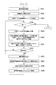
- FIG. 5 is a first diagram showing a processing flow of the kneading machine control device according to the present embodiment.
- the kneader control device 1 includes various types of materials included in the rubber material to be kneaded by the kneader 2, detailed information and identification information of the operation mode of the kneader 2 for kneading the rubber material, and the volume of the rubber material relative to the volume of the kneading chamber 12.
- Operation mode information indicating information such as a rate is stored for each of a plurality of different operation modes.
- the administrator operates the operation element or the like of the kneading machine control device 1 to select and input operation mode information indicating a desired operation mode among a plurality of different operation modes.
- the kneader control unit 115 of the kneader control device 1 detects an operation mode (step S101).
- the kneader control unit 115 also instructs the kneader 2 to start the kneading operation based on the operation mode information (step S102).
- the operation mode information is, for example, the timing at which the rubber raw material, silica and other additives contained in the rubber material are introduced into the kneader 2, the number of revolutions per unit time of the kneading rotor, the kneading time, and the position of the ram. It includes information on combinations such as up and down timing.
- the kneader control unit 115 of the kneader control device 1 detects the start timing of the kneading operation in the kneader 2 or the acquisition start timing of the measurement data (step S103).
- the start timing of the kneading operation or the acquisition timing of the measurement data may be, for example, the timing of the moment when the ram of the kneader 2 starts moving for the kneading operation from a predetermined standby position.
- the acquisition mode of the measurement data acquisition start timing may be different depending on the type of the kneading machine 2. For example, in the case of another kneader 2, the hopper 13 may be closed.
- the kneading machine control unit 115 detects the start timing of the kneading operation or the acquisition timing of the measurement data, it determines whether to end the process (step S104), and instructs the measurement data acquisition unit 111 to start measurement when it does not end. Do.
- the measurement data acquisition unit 111 determines measurement data of one or more of the above-mentioned monitoring target information based on an instruction of the kneader control unit 115.
- the predetermined interval may be, for example, every few seconds, every tens of seconds, or the like.
- the recording unit 113 records measurement data acquired at predetermined intervals in a storage unit such as the HDD 104 in association with an identifier indicating operation mode information.
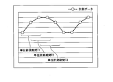
- FIG. 6 is a diagram showing a method of calculating statistical values of measurement values indicated by measurement data.
- the recording unit 113 calculates a statistical value of measurement values indicated by a plurality of measurement data acquired in a unit measurement period, and records the statistical value as measurement data in a storage unit such as the HDD 104 in association with an identifier indicating operation mode information. (Step S106). As shown in FIG. 6, the recording unit 113 sequentially calculates the statistical values calculated in each of the unit measurement periods T in which the unit measurement periods T (T1, T2, T3...) Are sequentially shifted according to the passage of time. It records in the storage unit as measurement data.
- the statistical value described here may be an average value, a median value or the like.
- the kneading machine control device 1 can accumulate the measurement data of the kneading machine 2 by the above processing.
- the kneader control device 1 accumulates a large number of such measurement data for each operation mode when the kneader 2 is in a normal state. That is, every time the kneader control device 1 operates the kneader 2, the measurement data is recorded in the storage unit.
- the kneader control device 1 detects the timing for starting acquisition of the measurement data in step S103, and matches the start timing of the measurement data in each of a series of operations from the start to the end of the kneading operation of the kneading machine 2. ing. Further, the kneading machine control device 1 records the statistical value of the measurement value as the measurement data by the process of step S106. By such processing, the kneader control device 1 suppresses an increase in acquisition of abnormal measurement data caused by a temporal deviation in measurement data collection, and reduces erroneous determination of abnormality.
- FIG. 7 is a second diagram showing the processing flow of the kneading machine control device according to the present embodiment.
- the kneader control device 1 performs abnormality determination of the kneader 2 in a state in which a large amount of measurement data is accumulated when the kneader 2 is in a normal state.
- the normal state of the kneader 2 may be, for example, within an initial predetermined period when using the kneader 2 or the like.
- the kneader control device 1 similarly performs the processing of the above-described steps S101 to S106.
- the determination unit 112 generates reference data selected from the measurement data recorded in the storage unit in the past (step S201).
- the kneading machine control device 1 receives from the administrator the selection of measurement data to be used as reference data in measurement data recorded in the past.
- the determination unit 112 may identify the measurement data regarded as normal from the measurement data recorded in the storage unit in the past by some process, and generate the measurement data as reference data. If all of the past measurement data can be regarded as normal data, the determination unit 112 may select all the past measurement data to be recorded as reference data.
- the determination unit 112 compares the measurement data recorded in the kneading operation of the kneading machine 2 this time with the reference data using the local outlier method to perform abnormality determination (step S202).
- the local outlier method is a method of determining an abnormality based on the density of data.
- FIG. 8 is a diagram showing an outline of the local outlier method.
- the local outlier method determines that the verification data is normal if the distance between the verification data (newly measured measurement data) and the reference data (normal data) selected from the past measurement data is close. On the other hand, the local outlier method determines that the verification data is abnormal if the distance between the verification data and the reference data is long.
- the determination unit 112 calculates Equation (1).
- the abnormality degree a (p) is expressed by equation (1).
- the determination unit 112 determines that the verification data is abnormal.
- the value of the degree of abnormality a (p) calculated by the equation (1) fluctuates by changing the value of “k”.
- the value of “k” may be determined automatically by the mixer control device 1 using a statistical method so that the abnormality degree a (p) is appropriately calculated.
- the administrator may set the value of “k” to an arbitrary value and input the value to the kneader control device 1.
- the judgment unit 112 notifies the output unit 116 of the abnormality.
- the output unit 116 receives the notification of abnormality, the output unit 116 outputs warning information to a monitor or the like (step S203).
- the output unit 116 may output warning information when receiving a notification of abnormality from the determining unit 112 continuously for a predetermined number of times, or when receiving notification of abnormality for a predetermined period.
- the output unit 116 may output warning information by sound other than the monitor.
- the recording unit 113 records the degree of abnormality a calculated by the determination unit 112 and the measurement data and the statistical value acquired by the measurement data acquisition unit 111.
- the kneader control device 1 having the function of the monitoring device automatically performs at least the abnormality determination of the kneader 2 and the recording of information based on the huge amount of measurement data by having such processing units. It is possible to more accurately perform the manager's early confirmation of the change of the state of the kneader 2 and the output of information leading to the oversight and the reduction of the change of the state. Thereby, the kneading machine control device 1 can suppress the deterioration and the variation of the quality of the rubber material generated by the kneading machine.
- the kneading machine control device 1 automatically performs recording of information based on a huge amount of measurement data for each operation mode, the time transition of measurement data of each operation mode can be recorded and comparison with the past becomes easy. Moreover, the kneading machine control device 1 can determine abnormality in real time using the measurement data. Therefore, the kneading machine control device 1 can prevent the outflow of the rubber material in which the abnormality has occurred to the next process.
- FIG. 9 is a view showing the rubber temperature and the degree of abnormality according to the time transition.
- the output unit 116 may output a state monitoring image indicating a graph showing the rubber temperature according to the time transition or a graph showing the degree of abnormality according to the time transition as shown in FIG. 8 to the monitor. Further, the output unit 116 monitors daily changes in the degree of abnormality included in the state monitoring image and the degree of deviation from the reference data of the verification data, and detects an abnormality due to a secular change in the machine state of the kneading machine 2. It is good (step S204).
- the output unit 116 monitors an increase or decrease in the degree of abnormality as indicated by the state monitoring image, predicts an increase tendency such as the number of times the abnormality degree exceeds the threshold per unit period, and performs predetermined calculation based on the increase tendency.
- An abnormality due to aging may be determined by a formula.
- the abnormal time prediction unit 114 may predict the time determined to be abnormal based on an increasing tendency such as the number of times the abnormality degree exceeds the threshold value per unit period (step S205). For example, the abnormal time prediction unit 114 counts the number of times that the abnormality degree is equal to or more than the threshold value per unit period, and a linear function that indicates an increasing tendency according to time due to the inclination of the increase in the number The future time of the intersection is calculated based on that. The abnormal time prediction unit 114 may output this future time as a predicted time determined to be abnormal. Then, for example, the kneading machine control device 1 stores in advance information indicating the cause of the abnormality assumed for each type of monitoring target information.
- the abnormal time prediction unit 114 may output information indicating the cause according to the type of the monitoring target information together with the predicted time. For example, when it is predicted that the degree of abnormality of the rubber temperature exceeds the threshold value, the abnormal time prediction unit 114 may output information on piping leaks and valve locations of the cooling water system as the cause along with the predicted time.
- the determination unit 112, the output unit 116, and the abnormal time prediction unit 114 may detect that the degree of abnormality exceeds the threshold value and notify the result to the kneading machine control unit 115 when the prediction is made.
- the kneader control unit 115 may perform feedback control of the kneader 2 so that the abnormality degree becomes equal to or less than the threshold (step S206).
- the kneader control device 1 can suppress an increase in the degree of abnormality.
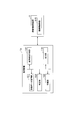
- FIG. 10 is a functional block diagram of the monitoring device.
- the monitoring device may be a device different from the kneader control device 1.
- the monitoring device 1b only needs to have at least the functions of the measurement data acquisition unit 111 and the determination unit 112.
- the measurement data acquisition unit 111 acquires measurement data of monitoring target information measured from a predetermined kneading operation start timing in a series of kneading operations of a rubber material in the kneading machine 2 in each unit of a series of kneading operations.
- the determination unit 112 performs abnormality determination by comparing the measurement data with reference data selected in the past measurement data of the monitoring target information.
- the monitoring device 1 b may also have the functions of the recording unit 113, the abnormal time prediction unit 114, and the output unit 116. These functional units are also similar to the functions described in the kneading machine control device 1.
- the kneader control unit 115 of the kneader control device 1 connected in communication has the abnormality degree It instructs to become below the threshold. In this case, the kneader control unit 115 of the kneader control device 1 performs feedback control.
- the above-mentioned kneader control device 1 and the monitoring device 1b have a computer system inside.
- the program for causing the kneader control device 1 and the monitoring device 1b to perform the above-described processes is stored in a computer readable recording medium of the kneader control device 1, and this program is stored in the kneader control device.
- the above process is performed by the computer 1 and the monitoring device 1b reading and executing.
- the computer-readable recording medium refers to a magnetic disk, a magneto-optical disk, a CD-ROM, a DVD-ROM, a semiconductor memory and the like.
- the computer program may be distributed to a computer through a communication line, and the computer that has received the distribution may execute the program.
- the program may be for realizing a part of the functions of each processing unit described above. Furthermore, it may be a so-called difference file (difference program) that can realize the above-described functions in combination with a program already recorded in the computer system.
- difference file difference program
- the present invention relates to a monitoring device, a monitoring method, and a program of a kneader for kneading a rubber material.
- Reference Signs List 1 kneader control device 1b: monitoring device 2: kneader 111: measurement data acquisition unit 112: determination unit 113: recording unit 114 Abnormal time prediction unit, 115 ... kneader control unit, 116 ... output unit
Landscapes
- Engineering & Computer Science (AREA)
- Mechanical Engineering (AREA)
- Chemical & Material Sciences (AREA)
- Chemical Kinetics & Catalysis (AREA)
- Physics & Mathematics (AREA)
- General Physics & Mathematics (AREA)
- General Engineering & Computer Science (AREA)
- Automation & Control Theory (AREA)
- Software Systems (AREA)
- Human Computer Interaction (AREA)
- Manufacturing & Machinery (AREA)
- Processing And Handling Of Plastics And Other Materials For Molding In General (AREA)
Abstract
Priority Applications (7)
| Application Number | Priority Date | Filing Date | Title |
|---|---|---|---|
| US16/062,648 US20200282371A1 (en) | 2017-08-31 | 2017-08-31 | Monitoring device, monitoring method, and program |
| CN201780093338.8A CN110944815B (zh) | 2017-08-31 | 2017-08-31 | 监视装置、监视方法及程序 |
| PCT/JP2017/031320 WO2019043861A1 (fr) | 2017-08-31 | 2017-08-31 | Dispositif et procédé de surveillance, et programme |
| JP2019538842A JP6780121B2 (ja) | 2017-08-31 | 2017-08-31 | 監視装置、監視方法、プログラム |
| DE112017008001.0T DE112017008001T5 (de) | 2017-08-31 | 2017-08-31 | Überwachungsvorrichtung, Überwachungsverfahren und Programm |
| KR1020207001775A KR102330169B1 (ko) | 2017-08-31 | 2017-08-31 | 감시 장치, 감시 방법, 프로그램 |
| TW107105752A TWI681275B (zh) | 2017-08-31 | 2018-02-21 | 監視裝置、監視方法、程式 |
Applications Claiming Priority (1)
| Application Number | Priority Date | Filing Date | Title |
|---|---|---|---|
| PCT/JP2017/031320 WO2019043861A1 (fr) | 2017-08-31 | 2017-08-31 | Dispositif et procédé de surveillance, et programme |
Publications (1)
| Publication Number | Publication Date |
|---|---|
| WO2019043861A1 true WO2019043861A1 (fr) | 2019-03-07 |
Family
ID=65525265
Family Applications (1)
| Application Number | Title | Priority Date | Filing Date |
|---|---|---|---|
| PCT/JP2017/031320 Ceased WO2019043861A1 (fr) | 2017-08-31 | 2017-08-31 | Dispositif et procédé de surveillance, et programme |
Country Status (7)
| Country | Link |
|---|---|
| US (1) | US20200282371A1 (fr) |
| JP (1) | JP6780121B2 (fr) |
| KR (1) | KR102330169B1 (fr) |
| CN (1) | CN110944815B (fr) |
| DE (1) | DE112017008001T5 (fr) |
| TW (1) | TWI681275B (fr) |
| WO (1) | WO2019043861A1 (fr) |
Cited By (1)
| Publication number | Priority date | Publication date | Assignee | Title |
|---|---|---|---|---|
| JP2021059058A (ja) * | 2019-10-07 | 2021-04-15 | 横浜ゴム株式会社 | 混練異常度学習装置、学習済モデルの生成方法及びプログラム |
Families Citing this family (5)
| Publication number | Priority date | Publication date | Assignee | Title |
|---|---|---|---|---|
| DE112017007730B4 (de) * | 2017-07-06 | 2023-06-01 | Mitsubishi Heavy Industries Machinery Systems, Ltd. | Mischmaschinensteuerungsvorrichtung, Mischmaschinensteuerungsverfahren und Programm |
| JP6886552B1 (ja) | 2020-05-29 | 2021-06-16 | 株式会社神戸製鋼所 | 機械学習方法、機械学習装置、機械学習プログラム、通信方法、及び混練装置 |
| US12478931B2 (en) | 2022-10-18 | 2025-11-25 | Lockheed Martin Corporation | Automated mixing system for cartridges containing materials |
| CN116351313B (zh) * | 2023-05-31 | 2023-07-28 | 广东奔富之堡智能家电工程技术研究中心有限公司 | 一种基于计算机控制的食品搅拌机智能控制系统 |
| DE102023120907A1 (de) * | 2023-08-07 | 2025-02-13 | Harburg-Freudenberger Maschinenbau Gmbh | Verfahren zur Festlegung eines Füllgrads und Innenmischer mit Steuervorrichtung |
Citations (6)
| Publication number | Priority date | Publication date | Assignee | Title |
|---|---|---|---|---|
| JPH06344334A (ja) * | 1993-06-07 | 1994-12-20 | Yokohama Rubber Co Ltd:The | ゴム混練機における混練判定方法 |
| JPH1015782A (ja) * | 1996-07-04 | 1998-01-20 | Sumitomo Electric Ind Ltd | 切削工具の異常検出装置 |
| JP2005246785A (ja) * | 2004-03-04 | 2005-09-15 | Yokohama Rubber Co Ltd:The | ゴム混練機の制御方法及びその装置 |
| JP2010214661A (ja) * | 2009-03-13 | 2010-09-30 | Moriyama:Kk | 混練判定システム |
| JP2014226910A (ja) * | 2013-05-27 | 2014-12-08 | 横浜ゴム株式会社 | 未加硫ゴムの混練異常判定方法および混練制御方法 |
| JP2017056666A (ja) * | 2015-09-18 | 2017-03-23 | 住友ゴム工業株式会社 | ゴム混練機における混練判定方法およびゴムの混練り方法 |
Family Cites Families (23)
| Publication number | Priority date | Publication date | Assignee | Title |
|---|---|---|---|---|
| US5056034A (en) * | 1989-11-20 | 1991-10-08 | Nordson Corporation | Method and apparatus for controlling the gas content of foam materials |
| JP2501547B2 (ja) * | 1992-10-27 | 1996-05-29 | 株式会社神戸製鋼所 | 密閉式混練機の油圧制御装置 |
| JP3786505B2 (ja) * | 1997-07-07 | 2006-06-14 | 横浜ゴム株式会社 | バンク量制御方法及びそれに使用されるロール混練装置、ロール混練装置群 |
| US5865535A (en) | 1997-11-06 | 1999-02-02 | M.A.Hannarubbercompounding, A Division Of M.A. Hanna Company | Dynamic mixer control in plastics and rubber processing |
| US6864310B2 (en) * | 1999-04-01 | 2005-03-08 | Pirelli Pneumatici S.P.A. | Process for manufacturing a tire compound |
| IT1317253B1 (it) * | 2000-04-14 | 2003-05-27 | Pirelli | Metodo di lavorazione di un impasto per mescole di pneumatici. |
| JP4024117B2 (ja) * | 2002-09-17 | 2007-12-19 | 株式会社ミツトヨ | 測定支援装置 |
| TWI227399B (en) * | 2003-12-12 | 2005-02-01 | Ind Tech Res Inst | Real-time monitoring system for abnormal situation and method thereof and real-time monitoring interface for complex abnormal situation |
| WO2010082526A1 (fr) * | 2009-01-13 | 2010-07-22 | 株式会社神戸製鋼所 | Machine de malaxage scellée |
| CN202147217U (zh) * | 2011-06-28 | 2012-02-22 | 上海三一精机有限公司 | 检测磨床加工状态的监控系统 |
| CN102363332B (zh) * | 2011-06-29 | 2013-12-11 | 双钱集团(如皋)轮胎有限公司 | 一种密炼机的胶料合格与否的判别方法 |
| TWI556194B (zh) * | 2012-06-29 | 2016-11-01 | 希科母股份有限公司 | 對象檢出裝置、對象檢出方法及對象檢出用電腦程式 |
| JP5910428B2 (ja) * | 2012-09-13 | 2016-04-27 | オムロン株式会社 | 監視装置、監視方法、プログラムおよび記録媒体 |
| JP5988495B2 (ja) * | 2013-02-06 | 2016-09-07 | 三菱重工マシナリーテクノロジー株式会社 | 混練機 |
| ES2695225T3 (es) * | 2013-08-20 | 2019-01-02 | Sony Corp | Dispositivo terminal, programa y dispositivo de procesamiento de información para comunicación de campo cercano |
| KR101548969B1 (ko) * | 2013-11-19 | 2015-09-01 | 한국타이어 주식회사 | 배합고무 제조용 밀폐식 혼합기의 전력제어방법 |
| JP6029576B2 (ja) * | 2013-12-20 | 2016-11-24 | 株式会社神戸製鋼所 | 密閉式混練装置のロータに加わるスラスト荷重の計測装置 |
| JP2015214119A (ja) * | 2014-05-13 | 2015-12-03 | 横浜ゴム株式会社 | ゴム混練物の品質評価方法 |
| JP2015226423A (ja) * | 2014-05-29 | 2015-12-14 | 住友電気工業株式会社 | 異常判定装置、異常判定方法、及びコンピュータプログラム |
| JP2017097631A (ja) * | 2015-11-25 | 2017-06-01 | ファナック株式会社 | 工作機械の稼働監視装置 |
| CN106142377B (zh) * | 2016-08-19 | 2018-10-30 | 盐城科高机电技术装备有限公司 | 橡胶密炼机耗能相关准余弦曲线型温度控制方法及装置 |
| CN106338981A (zh) * | 2016-09-23 | 2017-01-18 | 沈阳化工大学 | 动态多向局部离群因子算法的间歇过程在线故障检测方法 |
| CN106514891A (zh) * | 2016-12-19 | 2017-03-22 | 青岛科技大学 | 一种基于条状原料胶制备混炼胶的三相物料橡胶连续混炼机 |
-
2017
- 2017-08-31 WO PCT/JP2017/031320 patent/WO2019043861A1/fr not_active Ceased
- 2017-08-31 KR KR1020207001775A patent/KR102330169B1/ko not_active Expired - Fee Related
- 2017-08-31 JP JP2019538842A patent/JP6780121B2/ja not_active Expired - Fee Related
- 2017-08-31 CN CN201780093338.8A patent/CN110944815B/zh not_active Expired - Fee Related
- 2017-08-31 DE DE112017008001.0T patent/DE112017008001T5/de not_active Withdrawn
- 2017-08-31 US US16/062,648 patent/US20200282371A1/en not_active Abandoned
-
2018
- 2018-02-21 TW TW107105752A patent/TWI681275B/zh not_active IP Right Cessation
Patent Citations (6)
| Publication number | Priority date | Publication date | Assignee | Title |
|---|---|---|---|---|
| JPH06344334A (ja) * | 1993-06-07 | 1994-12-20 | Yokohama Rubber Co Ltd:The | ゴム混練機における混練判定方法 |
| JPH1015782A (ja) * | 1996-07-04 | 1998-01-20 | Sumitomo Electric Ind Ltd | 切削工具の異常検出装置 |
| JP2005246785A (ja) * | 2004-03-04 | 2005-09-15 | Yokohama Rubber Co Ltd:The | ゴム混練機の制御方法及びその装置 |
| JP2010214661A (ja) * | 2009-03-13 | 2010-09-30 | Moriyama:Kk | 混練判定システム |
| JP2014226910A (ja) * | 2013-05-27 | 2014-12-08 | 横浜ゴム株式会社 | 未加硫ゴムの混練異常判定方法および混練制御方法 |
| JP2017056666A (ja) * | 2015-09-18 | 2017-03-23 | 住友ゴム工業株式会社 | ゴム混練機における混練判定方法およびゴムの混練り方法 |
Cited By (2)
| Publication number | Priority date | Publication date | Assignee | Title |
|---|---|---|---|---|
| JP2021059058A (ja) * | 2019-10-07 | 2021-04-15 | 横浜ゴム株式会社 | 混練異常度学習装置、学習済モデルの生成方法及びプログラム |
| JP7372530B2 (ja) | 2019-10-07 | 2023-11-01 | 横浜ゴム株式会社 | 混練異常度学習装置、学習済モデルの生成方法及びプログラム |
Also Published As
| Publication number | Publication date |
|---|---|
| DE112017008001T5 (de) | 2020-07-02 |
| US20200282371A1 (en) | 2020-09-10 |
| KR20200019976A (ko) | 2020-02-25 |
| KR102330169B1 (ko) | 2021-11-24 |
| CN110944815A (zh) | 2020-03-31 |
| TW201913252A (zh) | 2019-04-01 |
| TWI681275B (zh) | 2020-01-01 |
| JP6780121B2 (ja) | 2020-11-04 |
| JPWO2019043861A1 (ja) | 2020-04-23 |
| CN110944815B (zh) | 2021-10-15 |
Similar Documents
| Publication | Publication Date | Title |
|---|---|---|
| JP6780121B2 (ja) | 監視装置、監視方法、プログラム | |
| CN103827505B (zh) | 用于监测泵的运行状态的方法和系统 | |
| US8676436B2 (en) | Method for monitoring the oil system of a turbomachine | |
| US9689790B2 (en) | Environmental control systems and techniques for monitoring heat exchanger fouling | |
| TWI684103B (zh) | 混練機控制裝置,混練機控制方法,混練機控制程式 | |
| US11203273B2 (en) | Method and apparatus for indicating a state of health of a battery | |
| US20200310396A1 (en) | Using a digital twin to facilitate environment-specific prognostic-surveillance operations for engineering assets in the field | |
| KR101952992B1 (ko) | 지능형 펌프 모니터링 및 제어 시스템 | |
| CN104541216A (zh) | 用于检测机械系统|以及调整与所述机械系统关联的极限值以反映|机械系统的当前条件的监测系统和方法 | |
| EP2027513B1 (fr) | Commande de diagnostic en cours de procédé et systèmes de surveillance | |
| EP2778420B1 (fr) | Procédé permettant d'estimer la durée de vie d'une pompe à engrenages et appareil d'extrusion de caoutchouc | |
| JP2004240642A (ja) | プラント機器の保守支援装置 | |
| JP6503541B2 (ja) | ポンプ異常検知システム、ポンプ異常検知方法、及びポンプ異常検知プログラム | |
| CN112739521B (zh) | 挤压设备的诊断故障排除系统 | |
| JP6369895B2 (ja) | モータ異常検知システム、モータ異常検知方法、及びモータ異常検知プログラム | |
| JP6952622B2 (ja) | 性能評価方法、性能評価装置、及び性能評価システム | |
| US20220163504A1 (en) | Sensor Monitoring System with Cloud Based Interface | |
| TWI875205B (zh) | 狀態監視系統及狀態監視方法 | |
| EP4248122B1 (fr) | Système de surveillance de capteur à interface en nuage | |
| JP6952621B2 (ja) | 性能評価方法、性能評価装置、及び性能評価システム | |
| JP2024016374A (ja) | 監視システム、監視方法及びプログラム | |
| CN120370019A (zh) | 冷却塔风机电流预测方法、故障检测方法及相关装置 | |
| US20220042429A1 (en) | Equipment lubricant water ingress measurement system and method | |
| CN120777796A (zh) | 制冷系统中水温控制方法 |
Legal Events
| Date | Code | Title | Description |
|---|---|---|---|
| 121 | Ep: the epo has been informed by wipo that ep was designated in this application |
Ref document number: 17923747 Country of ref document: EP Kind code of ref document: A1 |
|
| ENP | Entry into the national phase |
Ref document number: 2019538842 Country of ref document: JP Kind code of ref document: A |
|
| ENP | Entry into the national phase |
Ref document number: 20207001775 Country of ref document: KR Kind code of ref document: A |
|
| 122 | Ep: pct application non-entry in european phase |
Ref document number: 17923747 Country of ref document: EP Kind code of ref document: A1 |