WO2019043900A1 - Élément creux - Google Patents
Élément creux Download PDFInfo
- Publication number
- WO2019043900A1 WO2019043900A1 PCT/JP2017/031524 JP2017031524W WO2019043900A1 WO 2019043900 A1 WO2019043900 A1 WO 2019043900A1 JP 2017031524 W JP2017031524 W JP 2017031524W WO 2019043900 A1 WO2019043900 A1 WO 2019043900A1
- Authority
- WO
- WIPO (PCT)
- Prior art keywords
- bending
- frame
- filling
- hollow member
- longitudinal direction
- Prior art date
- Legal status (The legal status is an assumption and is not a legal conclusion. Google has not performed a legal analysis and makes no representation as to the accuracy of the status listed.)
- Ceased
Links
Images







































Classifications
-
- B—PERFORMING OPERATIONS; TRANSPORTING
- B62—LAND VEHICLES FOR TRAVELLING OTHERWISE THAN ON RAILS
- B62D—MOTOR VEHICLES; TRAILERS
- B62D21/00—Understructures, i.e. chassis frame on which a vehicle body may be mounted
- B62D21/15—Understructures, i.e. chassis frame on which a vehicle body may be mounted having impact absorbing means, e.g. a frame designed to permanently or temporarily change shape or dimension upon impact with another body
-
- B—PERFORMING OPERATIONS; TRANSPORTING
- B62—LAND VEHICLES FOR TRAVELLING OTHERWISE THAN ON RAILS
- B62D—MOTOR VEHICLES; TRAILERS
- B62D21/00—Understructures, i.e. chassis frame on which a vehicle body may be mounted
- B62D21/15—Understructures, i.e. chassis frame on which a vehicle body may be mounted having impact absorbing means, e.g. a frame designed to permanently or temporarily change shape or dimension upon impact with another body
- B62D21/152—Front or rear frames
-
- B—PERFORMING OPERATIONS; TRANSPORTING
- B60—VEHICLES IN GENERAL
- B60R—VEHICLES, VEHICLE FITTINGS, OR VEHICLE PARTS, NOT OTHERWISE PROVIDED FOR
- B60R19/00—Wheel guards; Radiator guards, e.g. grilles; Obstruction removers; Fittings damping bouncing force in collisions
- B60R19/02—Bumpers, i.e. impact receiving or absorbing members for protecting vehicles or fending off blows from other vehicles or objects
- B60R19/24—Arrangements for mounting bumpers on vehicles
- B60R19/26—Arrangements for mounting bumpers on vehicles comprising yieldable mounting means
- B60R19/34—Arrangements for mounting bumpers on vehicles comprising yieldable mounting means destroyed upon impact, e.g. one-shot type
-
- B—PERFORMING OPERATIONS; TRANSPORTING
- B62—LAND VEHICLES FOR TRAVELLING OTHERWISE THAN ON RAILS
- B62D—MOTOR VEHICLES; TRAILERS
- B62D21/00—Understructures, i.e. chassis frame on which a vehicle body may be mounted
- B62D21/02—Understructures, i.e. chassis frame on which a vehicle body may be mounted comprising longitudinally or transversely arranged frame members
-
- B—PERFORMING OPERATIONS; TRANSPORTING
- B62—LAND VEHICLES FOR TRAVELLING OTHERWISE THAN ON RAILS
- B62D—MOTOR VEHICLES; TRAILERS
- B62D25/00—Superstructure or monocoque structure sub-units; Parts or details thereof not otherwise provided for
-
- B—PERFORMING OPERATIONS; TRANSPORTING
- B62—LAND VEHICLES FOR TRAVELLING OTHERWISE THAN ON RAILS
- B62D—MOTOR VEHICLES; TRAILERS
- B62D25/00—Superstructure or monocoque structure sub-units; Parts or details thereof not otherwise provided for
- B62D25/04—Door pillars ; windshield pillars
-
- B—PERFORMING OPERATIONS; TRANSPORTING
- B62—LAND VEHICLES FOR TRAVELLING OTHERWISE THAN ON RAILS
- B62D—MOTOR VEHICLES; TRAILERS
- B62D25/00—Superstructure or monocoque structure sub-units; Parts or details thereof not otherwise provided for
- B62D25/08—Front or rear portions
-
- B—PERFORMING OPERATIONS; TRANSPORTING
- B62—LAND VEHICLES FOR TRAVELLING OTHERWISE THAN ON RAILS
- B62D—MOTOR VEHICLES; TRAILERS
- B62D29/00—Superstructures, understructures, or sub-units thereof, characterised by the material thereof
- B62D29/001—Superstructures, understructures, or sub-units thereof, characterised by the material thereof characterised by combining metal and synthetic material
- B62D29/002—Superstructures, understructures, or sub-units thereof, characterised by the material thereof characterised by combining metal and synthetic material a foamable synthetic material or metal being added in situ
-
- F—MECHANICAL ENGINEERING; LIGHTING; HEATING; WEAPONS; BLASTING
- F16—ENGINEERING ELEMENTS AND UNITS; GENERAL MEASURES FOR PRODUCING AND MAINTAINING EFFECTIVE FUNCTIONING OF MACHINES OR INSTALLATIONS; THERMAL INSULATION IN GENERAL
- F16S—CONSTRUCTIONAL ELEMENTS IN GENERAL; STRUCTURES BUILT-UP FROM SUCH ELEMENTS, IN GENERAL
- F16S3/00—Elongated members, e.g. profiled members; Assemblies thereof; Gratings or grilles
-
- B—PERFORMING OPERATIONS; TRANSPORTING
- B60—VEHICLES IN GENERAL
- B60R—VEHICLES, VEHICLE FITTINGS, OR VEHICLE PARTS, NOT OTHERWISE PROVIDED FOR
- B60R19/00—Wheel guards; Radiator guards, e.g. grilles; Obstruction removers; Fittings damping bouncing force in collisions
- B60R19/02—Bumpers, i.e. impact receiving or absorbing members for protecting vehicles or fending off blows from other vehicles or objects
- B60R19/18—Bumpers, i.e. impact receiving or absorbing members for protecting vehicles or fending off blows from other vehicles or objects characterised by the cross-section; Means within the bumper to absorb impact
- B60R2019/1806—Structural beams therefor, e.g. shock-absorbing
- B60R2019/1813—Structural beams therefor, e.g. shock-absorbing made of metal
-
- B—PERFORMING OPERATIONS; TRANSPORTING
- B60—VEHICLES IN GENERAL
- B60R—VEHICLES, VEHICLE FITTINGS, OR VEHICLE PARTS, NOT OTHERWISE PROVIDED FOR
- B60R19/00—Wheel guards; Radiator guards, e.g. grilles; Obstruction removers; Fittings damping bouncing force in collisions
- B60R19/02—Bumpers, i.e. impact receiving or absorbing members for protecting vehicles or fending off blows from other vehicles or objects
- B60R19/24—Arrangements for mounting bumpers on vehicles
- B60R2019/247—Fastening of bumpers' side ends
-
- B—PERFORMING OPERATIONS; TRANSPORTING
- B60—VEHICLES IN GENERAL
- B60Y—INDEXING SCHEME RELATING TO ASPECTS CROSS-CUTTING VEHICLE TECHNOLOGY
- B60Y2306/00—Other features of vehicle sub-units
- B60Y2306/01—Reducing damages in case of crash, e.g. by improving battery protection
-
- B—PERFORMING OPERATIONS; TRANSPORTING
- B62—LAND VEHICLES FOR TRAVELLING OTHERWISE THAN ON RAILS
- B62D—MOTOR VEHICLES; TRAILERS
- B62D25/00—Superstructure or monocoque structure sub-units; Parts or details thereof not otherwise provided for
- B62D25/20—Floors or bottom sub-units
-
- Y—GENERAL TAGGING OF NEW TECHNOLOGICAL DEVELOPMENTS; GENERAL TAGGING OF CROSS-SECTIONAL TECHNOLOGIES SPANNING OVER SEVERAL SECTIONS OF THE IPC; TECHNICAL SUBJECTS COVERED BY FORMER USPC CROSS-REFERENCE ART COLLECTIONS [XRACs] AND DIGESTS
- Y02—TECHNOLOGIES OR APPLICATIONS FOR MITIGATION OR ADAPTATION AGAINST CLIMATE CHANGE
- Y02T—CLIMATE CHANGE MITIGATION TECHNOLOGIES RELATED TO TRANSPORTATION
- Y02T30/00—Transportation of goods or passengers via railways, e.g. energy recovery or reducing air resistance
Definitions
- the present invention relates to hollow members.
- One of the methods of forming a structure such as a car, a railway vehicle, an aircraft or a building is a method of forming a structure by a frame corresponding to a skeleton and other structural members (skin and the like).
- a frame is typically required to have high strength and light weight from the viewpoint of improving the strength of the structure and suppressing costs.
- strengthening and thinning of steel plates forming the frame have been promoted.
- Patent Document 1 discloses a technique in which the filling member is disposed without a gap inside the frame.
- the frame deforms when a load is applied to the frame as in a car crash. At this time, deformation occurs in the cross section of the frame. This deformation is called cross-sectional deformation.
- the load applied to the frame exceeds a predetermined value, the frame is buckled and the load-bearing performance of the frame is significantly reduced. The fact that buckling occurs means that it bends. In this case, the energy absorption amount assumed for the frame may not be secured.
- the inventors considered that it is useful to further increase the mass efficiency with respect to the improvement of the energy absorption amount by the filling member and to suppress the out-of-plane deformation that causes the reduction of the energy absorption amount of the frame.
- the effective arrangement of the filling member for suppressing the out-of-plane deformation and improving the energy absorption amount of the frame has not been studied at all.
- An object of the present invention is to provide a new and improved hollow member which realizes energy absorption at load input with high mass efficiency.
- a hollow metal member having a bending induction portion in a part in the longitudinal direction, and in close contact with the metal member, on both sides in the longitudinal direction of the bending induction portion
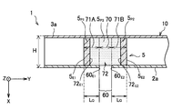
- a resin material disposed and disposed at least in a range of less than 5 ⁇ 6 of the cross-sectional height of the metal member in the longitudinal direction from the end of the bending induction portion to the outside;
- the hollow member in which the amount (volume) of the resin material per longitudinal length is larger at the outside of the bending induced portion than at the inside of the bending induced portion is provided.
- the end of the resin material closer to the bending induced portion overlaps the bending induced portion, or the height of the cross-section of the metal member outward from the end of the bending induced portion It may be arranged in the range of less than 5/6.
- the two resin materials are disposed with the bending inducing portion interposed therebetween.
- the resin material may be one, and a cavity may be provided at a position overlapping the bending induced portion of the resin material in the longitudinal direction, and an end may be provided on both sides of the bending induced portion.
- the longitudinal end of the cavity may be located inside the bend inducer or may be located outside the bend inducer.
- the end of the resin material closer to the bend inducing portion overlaps the bend inducing portion, or the end of the bend inducing portion on the outer side of the bend inducing portion is a cross section of the metal member It may be arranged in the range of 1 to 2 of the height.
- the distance in the longitudinal direction from the end of the resin material farther from the bending induction portion to the longitudinal direction to the end of the bending induction portion is 5 ⁇ 6 or less of the height of the cross section of the metal member May be
- the metal member has a bottom wall portion, a pair of side wall portions rising from both ends of the bottom wall portion, and a top wall portion facing the bottom wall portion, and the bottom wall portion and the pair of side wall portions And the top wall may form a closed cross section.
- the resin material may be disposed in close contact with the inner surface of at least one of the bottom wall portion or the top wall portion.
- the resin material may be disposed in intimate contact with the inner surface of at least one of the pair of side wall portions.
- a second metal plate may be disposed in contact with the first metal plate forming the metal member inside the metal member.
- the resin material may be disposed in close contact with the second metal plate.
- the first metal plate forming the metal member has a hole, the resin material is made of a foamed resin, and the resin material penetrates the hole and both the outer surface and the inner surface of the first metal plate are formed. It may be disposed in close contact with the
- the hole edge of the hole may be located more inward of the metal member than the first metal plate forming the metal member.
- the hole may be a burring hole in which the hole edge of the hole protrudes inward from the outside of the first metal plate forming the metal member.
- the hole may be provided with a depression recessed inward of the metal member relative to the first metal plate forming the metal member, and the hole may be provided inside the depression. .
- the bending induction portion may be a portion where the total plastic moment of the metal member changes in the longitudinal direction.
- the bending induction portion may be a portion having a curvature radius of 260 mm or less of a locus of the center of gravity along the longitudinal direction formed by the center of gravity of a cross section of the metal member.
- the bending induction portion may be a thickness changing portion.
- the bending inducing portion may be a portion provided with a recess.
- the bend inducing portion may be a portion provided with a convex portion.
- the bend inducing portion may be a portion provided with a hole.
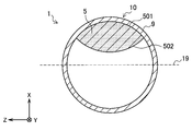
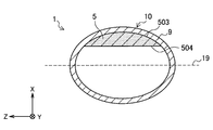
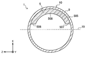
- the resin material has the bending induction portion from a boundary bisecting the cross section in the height direction of the cross section defined in a direction from the center of gravity of the cross section toward the bending induction portion It may be placed on the side.
- the periphery of the bending induction portion means at least a part of a range of less than 5 ⁇ 6 of the cross-sectional height of the metal member from the longitudinal end of the bending induction portion to the outside.
- the energy absorption amount at the time of load input can be improved. Further, since the place where the out-of-plane deformation is to be suppressed is limited in the longitudinal direction to the periphery of the bending induction portion, the energy absorption amount at the time of load input can be improved with high mass efficiency.
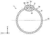
- FIG. 6 is a cross-sectional view taken along the line II-II of the frame shown in FIG.
- FIG. 13 is a cross-sectional view taken along the line VV of the frame shown in FIG. 12; It is sectional drawing in the VI-VI cutting line of the flame
- FIG. 23 is a cross-sectional view taken along the line VIII-VIII of the frame shown in FIG. It is sectional drawing of the flame
- FIG. 40 is a cross-sectional view of the frame shown in FIG. 39 taken along line XIII-XIII.
- FIG. 40 is a cross sectional view taken along a line XIV-XIV of the frame shown in FIG. 39.
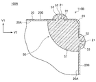
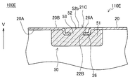
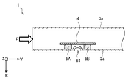
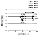
- FIG. 1 It is a top view which shows the structure of the sample used for the cross tension test which concerns on Example 1 and Example 2 which concern on the 4th Embodiment of this invention. It is a side sectional view showing the composition of the sample concerning Example 1 concerning the embodiment. It is a side sectional view showing the composition of the sample concerning Example 2 concerning the embodiment. It is a side sectional view showing the composition of the sample concerning the comparative example concerning the embodiment. It is a graph which shows the maximum load of each sample measured by the cross tension test concerning the embodiment. It is a figure for demonstrating the simulation setting of the Example regarding the arrangement
- FIG. 7 is a view showing a list of cross-sectional views before and after deformation of Embodiments 1 to 5 and Reference Example 1 regarding the arrangement range of the filling member. It is a graph which shows the absorbed energy ratio which is a ratio of the amount of energy absorption when the amount of energy absorption of reference example 1 of Examples 1 to 5 and Reference Example 1 is 1 regarding the arrangement range of the filling member.
- FIG. 18 is a view showing a list of cross-sectional views before and after deformation of Embodiments 6 to 10 and Reference Example 2 regarding the arrangement range of the filling member.
- the hollow member according to an embodiment of the present invention can be used as various structural members.
- a hollow member according to an embodiment is used for a vehicle frame as a vehicle structural member will be described.
- the vehicle frame is simply referred to as a frame.
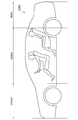
- FIG. 1 is a schematic configuration view of a vehicle for explaining an application target of a frame according to the present embodiment.
- a vehicle body provided in a vehicle 1000 such as a general automobile shown in FIG. 1 can be classified into a front structure (FRONT), a rear structure (REAR), and a cabin structure (CABIN).
- FRONT front structure
- RRR rear structure
- CABIN cabin structure
- the front structure and the rear structure also called “crushable zone” have a function (shock absorbing function) to absorb and mitigate an impact to the vehicle.
- the crushable zone is crushed by collision energy at the time of a vehicle collision. That is, in order to ensure the safety of the passenger in the cabin at the time of a vehicle collision, the front structure and the rear structure are required to be a structure that absorbs energy (collision energy) generated by the collision. Therefore, the frames constituting the front structure and the rear structure are required to absorb collision energy even when bending or crushing occurs at the time of collision.
- the frames used for the front structure and the rear structure are, for example, front side members, rear side members, bumper reinforcements, and crash boxes.
- the front side member includes a front side member rear that constitutes a rear end, and a front side member front that constitutes a front side than the rear end.
- the rear side member includes a rear side member rear that constitutes a rear end, and a rear side member front that constitutes a front side than the rear end.
- the cabin structure is also referred to as a "safety zone" and has a function (passenger protection function) for securing the safety of a passenger on the vehicle at the time of a vehicle collision. That is, in order to ensure the safety of the occupant in the event of a vehicle collision, the cabin structure is required to be a structure that is not easily crushed against impact force. Therefore, the frame constituting the cabin structure is required to be resistant to deformation and to have high load bearing performance.
- the frame used for the cabin structure is, for example, a front pillar (A pillar), a center pillar (B pillar), a rear pillar (C pillar, D pillar), a front pillar lower (A pillar lower), a side sill, a roof rail, a cross member, It is a tunnel etc.
- a structural material for example, a steel plate
- the frames constituting the above-described front structure, rear structure and cabin structure are also being replaced with thinned high-strength steel plates.
- the replacement requires that at least one of the amount of impact energy absorption and the load bearing performance be equal to that of the conventional frame.
- the thickness of the frame formed by the high strength steel plate can be thinner than the frame formed by the conventional steel plate. Thereby, it is considered that the weight of the frame can be reduced while maintaining the collision performance of the high strength frame equivalent to that of the conventional frame.
- FIG. 116 is a cross-sectional view showing an example of a change in cross-sectional shape of the thinned frame 900.
- FIG. 116 when a collision load is applied in the longitudinal direction (Y-axis direction) of the frame 900 and bending occurs in the frame 900, the bottom wall portion 900a bulges in the out-of-plane direction, and the side wall portion 900b faces It deforms so as to bend outward (cross-sectional shape 901).
- the bottom wall 900a is a bending inner side. As the bending further progresses, the out-of-plane deformation of the bottom wall portion 900a and the side wall portion 900b further progresses. As a result, the frame 900 buckles.
- the cross-sectional shape 902 of the buckled frame 900 deviates significantly from the original cross-sectional shape.
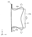
- FIG. 117 is a cross-sectional view showing another example of the change of the cross-sectional shape of the thinned frame 910.
- a collision load is applied in the longitudinal direction (Y-axis direction) of the frame 910 or a collision load is applied perpendicularly to the surface of the bottom wall portion 910a and the frame 910 is bent
- the bottom The wall 910 a is recessed and the side wall 910 b is deformed so as to bend (cross-sectional shape 911).
- the bottom wall part 910a is a bending inner side. As the bending progresses further, the bottom wall 910a and the side wall 910b are further deformed in the out-of-plane direction.
- the frame 910 buckles.
- the cross-sectional shape 912 of the buckled frame 910 deviates significantly from the original cross-sectional shape.
- FIGS. 116 and 117 occurs in the frame 900 (910), the cross section collapses flat. Such deformation is called cross-sectional collapse.
- the flexural rigidity of the structural material depends on the thickness of the structural material. If the thickness of the frame is thinner than in the prior art, the surface of the frame is likely to be deformed out of plane. As a result, the bending stiffness of the frame is reduced. That is, bending deformation of the frame as shown in FIGS. 116 and 117 is likely to occur. When the cross section of the frame is deformed, the bending rigidity is gradually reduced because the height (thickness) of the frame is gradually reduced. Then, bending deformation progresses, and when buckling occurs, bending rigidity is rapidly reduced. As a result of the buckling, the load carrying capacity of the frame is extremely lower than the designed value. Therefore, the collision safety performance that the frame conventionally has is reduced.
- the present inventors first provided a bending induction part which induces a bending deformation at the time of load input, and produced a prototype of a frame in which a filling member was arranged in the bending induction part.
- the filling member is placed on the frame, the place where it is placed is increased in thickness by the filling member, thereby increasing the bending rigidity.
- the bending induction portion preferentially deforms out of plane, it is effective to arrange the filling member in the bending induction portion.
- the present inventors have found that when the filling member is disposed all over the entire bending induction part in the longitudinal direction, the bending induction part may not induce bending deformation.
- the rigidity of the frame in the bending induced portion being increased by the filling member, bending deformation occurs in a portion other than the bending induced portion of the frame at the time of load input.
- the portion other than the bending induction portion is preferentially deformed out of plane, the effect of suppressing the out-of-plane deformation of the frame by the filling member disposed in the bending induction portion is significantly reduced.
- the present inventors arrange the filling member around the bending induction portion, and further, the amount of the filling member arranged in at least a part of the region overlapping the bending induction portion in the longitudinal direction compared to the periphery of the bending induction portion
- the filling member By reducing the (volume), it was conceived to be a hollow member capable of improving the energy absorption amount at the time of load input with high mass efficiency. Since the peripheral part of the bending induction part is also out of plane in the longitudinal direction due to the out-of-plane deformation of the bending induction part, it is efficient to arrange the filling member in the peripheral part of the bending induction part in the longitudinal direction It becomes arrangement.
- the amount of the filling member per longitudinal length in the region overlapping with the bending induced portion in the longitudinal direction is suppressed compared to the periphery of the bending induced portion.
- the filling member may not be disposed in at least a part of the region overlapping the bending induction in the longitudinal direction.
- at least a part of the region overlapping the bending inducing portion in the longitudinal direction may be provided with a place where the amount of the filling member disposed per longitudinal length is smaller than the periphery of the bending inducing portion.
- the place where the amount of the filling member to be placed is small may be either the case where the placement region of the filling member is narrow or the case where the thickness of the placed filling member is thin.
- the places where the filling members of the first and second examples are not disposed, or the places where the amount of the filling member to be placed is small extend to all of the bending induction parts and extend to a part of the periphery of the bending induction parts. It does not matter. However, if the area in which the filling member is not disposed is too far from the bending inducing portion, the effect of the filling member is reduced.
- the filling member It is necessary to arrange a part of the filling member in the area in the longitudinal direction and within half the cross sectional height of the frame from the end of the bending induction part.
- bending deformation can be induced at least in the bending induction portion.
- the frame is made to be tenaciously and energy-absorptive as a result of the rigidity of the frame being enhanced by the filling members disposed around the bending induction portion until the frame is deformed out of plane and reaches buckling.
- the amount of the filling member that leads to an increase in weight can also be suppressed.
- a hollow member according to an embodiment of the present invention will be described.
- the load is, for example, a collision load.
- the energy absorption amount at the time of load input is the absorption amount of collision energy by the frame when the collision load is input. To improve the amount of collision energy absorption means to improve the collision safety performance.
- the resin material is disposed in close contact with the second metal plate and adjacent to or separated from the bending induction portion in the longitudinal direction.
- the arrangement of the filling member in the longitudinal direction adjacent to the bending induction means that the region in which the filling member is not arranged completely overlaps the bending induction in the longitudinal direction.
- the arrangement of the filling member in the longitudinal direction separately from the bending inducing portion means that the region in which the filling member is not disposed extends in the longitudinal direction to the outside of the bending inducing portion.
- the filling member in the case where the filling member is disposed in a range overlapping the bending induced portion in the longitudinal direction, the filler is disposed in the peripheral region of the bending induced portion
- the filler is disposed in the peripheral region of the bending induced portion
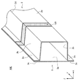
- FIG. 2 is a perspective view showing a schematic configuration of an example of the frame 1 according to the first embodiment of the present invention.
- the frame 1 in the present specification is an example of a hollow member.
- the hollow member is used, for example, as a front side member and a rear side member of a car.
- the front side member includes a front side member rear that constitutes a rear end, and a front side member front that constitutes a front side than the rear end.
- the rear side member includes a rear side member rear that constitutes a rear end, and a rear side member front that constitutes a front side than the rear end.
- the hollow member is also used for a pillar of a car.
- the pillars include, for example, a front pillar (A pillar), a center pillar (B pillar), a rear pillar (C pillar, D pillar), and a front pillar lower (A pillar lower).
- the hollow member can also be used for floor reinforcement, floor cross member, bumper reinforcement, side sill, roof side rail, roof center reinforcement, crash box, tunnel and the like. Further, the hollow member is applicable not only to automobiles but also to other vehicles and self-propelled machines. Other vehicles and self-propelled machines include, for example, large-sized vehicles such as motorcycles, buses or trailers, trailers, railway vehicles, construction machines, mining machines, agricultural machines, general machines, aircraft, ships, etc. .
- the frame 1 according to the present embodiment includes the first structural member 2, the second structural member 3, the reinforcement 4, and the filling members 5 (5 ⁇ / b> A and 5 ⁇ / b> B).
- the hollow member 10 according to the present embodiment is formed of the first structural member 2 and the second structural member 3.
- FIG. 3 is a cross-sectional view showing a cross section orthogonal to the Y-axis direction of an example of the hollow member 10 according to the present embodiment.
- FIGS. 2 and 3 the configuration of the frame 1 according to the present embodiment will be described with reference to FIGS. 2 and 3.
- the 1st structural member 2 which concerns on this embodiment is an example of the structural member which forms the elongate hollow member 10, and has a hat-shaped cross-sectional shape.
- the first structural member 2 has a bottom wall 2a extending in the longitudinal direction (Y-axis direction), side walls 2b and 2b, flanges 2c and 2c, and ridges 2d and 2d. , 2e, 2e.
- the side wall portion 2 b is provided upright from both ends in the Z axis direction (width direction) of the bottom wall portion 2 a.
- the angle formed by the side wall portion 2b and the bottom wall portion 2a is not limited to the substantially vertical but is appropriately set according to the design of the member.
- the ridge line portion 2d is a portion which becomes a boundary between the bottom wall portion 2a and the side wall portion 2b.
- the flange portion 2c is provided so as to rise outward along the Z-axis direction from the end opposite to the bottom wall portion 2a of the side wall portion 2b.
- the angle between the flange portion 2c and the side wall portion 2b may be appropriately determined according to the design of the member.
- the ridge line portion 2e is a portion which is a boundary between the side wall portion 2b and the flange portion 2c.
- the second structural member 3 is an example of a structural member in which the hollow member 10 is formed together with the first structural member 2.
- the second structural member 3 is a plate-like member. As shown in FIG. 3, the second structural member 3 has a top wall 3 a and joints 3 c and 3 c.
- the top wall 3 a is a portion facing the bottom wall 2 a of the first structural member 2.
- the joint 3c is a portion that abuts on the flange 2c of the first structural member 2 and is joined to the flange 2c. That is, the top wall portion 3a is a portion corresponding to a region existing between the connection portions of the second structural member 3 and the pair of ridge portions 2e.
- the joint portion 3c is a portion in contact with the region of the flange portion 2c which is sandwiched between the ridge portion 2e and the end of the flange portion 2c in the second structural member 3.
- the hollow member 10 is formed of the first structural member 2 and the second structural member 3 by joining the flange portion 2c and the joint portion 3c. At this time, as shown in FIG. 3, the hollow member 10 has a closed cross section.
- the closed cross section is formed by the bottom wall portion 2a, the pair of side wall portions 2b and 2b, and the top wall portion 3a.
- the joining method of the flange part 2c and the junction part 3c is not specifically limited.
- the joining method may be welding such as laser welding, arc welding, spot welding, etc., mechanical bonding such as rivet or bolt fastening, or adhesion by an adhesive or brazing.
- the flange 2c and the joint 3c are joined by spot welding.
- the shape of the closed cross section which the hollow member 10 has is a substantially polygon.
- a substantially polygon means a closed plane figure which can be approximately expressed by a plurality of line segments.
- the closed cross section shown in FIG. 3 is a substantially quadrilateral having four line segments (corresponding to the bottom wall 2a, the side wall 2b, and the top wall 3a) and four apexes (corresponding to the ridges 2d and 2e). is there.
- the substantially square includes a rectangle, a trapezoid and the like.
- the hollow member 10 includes the bottom wall portion 2a and the pair of side wall portions 2b and 2b. It will be described as being formed by the ceiling wall 3a. An example of the shape of the closed cross section of the hollow member 10 will be described later.
- the hollow member 10 may have a closed cross-sectional structure as described above, or may have an open cross-sectional structure such as a U-shape. Further, the shape of the cross section orthogonal to the longitudinal direction of the hollow member 10 is not particularly limited. For example, the cross-sectional shape of the hollow member 10 may be a rectangular cross section or a circular cross section.
- the hollow member according to the present embodiment is an example of a metal member.
- the first structural member 2 and the second structural member 3 according to the present embodiment are formed of, for example, a metal plate such as a steel plate.
- the 1st structural member 2 and the 2nd structural member 3 which concern on this embodiment are an example of a 1st metal plate.
- the plate thickness of both structural members is preferably 2.3 mm or less in a frame structure often used in a large vehicle such as a bus, and the plate is used in a monocoque structure vehicle often used in a normal size vehicle.
- the thickness is preferably 1.8 mm or less, and in a small vehicle such as a motorcycle, the plate thickness is preferably 1.4 mm or less.
- the bending induction portion when the bending induction portion is provided on the relatively thin metal plate having such a plate thickness, the bending induction portion can generate the out-of-plane deformation prior to other portions.
- the strength of the first structural member 2 and the second structural member 3 according to the present embodiment is not particularly limited.
- the tensile strength of both structural members is preferably 780 MPa or more.
- the tensile strength of both structural members is more preferably 980 MPa or more. This is because the metal member constituting the hollow member is disposed on the surface to which the highest tensile stress is applied in the bending induced portion.
- Members with low tensile strength also have low yield strength. When the yield strength is low, the hollow member is easily plastically deformed when out-of-plane deformation occurs. As plastic deformation progresses, the hollow member buckles.
- the reinforcement 4 is disposed inside the hollow member 10 as shown in FIG.
- the reinforcement 4 has a main surface 4a and a joint 4b, as shown in FIG.
- the reinforcement 4 is disposed so as to face the bottom wall 2 a and the top wall 3 a in the main surface 4 a according to the present embodiment.
- the bonding portion 4b is bonded to the side wall portion 2b.
- the main surface portion 4a is provided so as to bridge between the pair of side wall portions 2b and 2b.
- the reinforcement 4 suppresses the deformation of the pair of side wall portions 2b, 2b, so that the cross-sectional deformation of the hollow member 10 can be suppressed.
- the joining method of the junction part 4b and the side wall part 2b is not specifically limited.
- the said joining method is not specifically limited similarly to joining of the flange part 2c and the junction part 3c.
- the joint 4 b and the side wall 2 b are joined by spot welding.
- the reinforcement 4 also has a function as a threshold plate for dividing the arrangement area of the filling member 5.
- the reinforcement 4 according to the present embodiment is an example of a second metal plate.
- the reinforcement 4 according to the present embodiment is formed of, for example, a metal plate such as a steel plate.
- the material forming the reinforcement 4 may be a plastic, a carbon fiber, an alloy plate or a composite material.
- the filling member 5 is a resin material.
- the filling member 5 is made of urethane resin, epoxy resin or any other resin.
- the filling member 5 can be formed with a Young's modulus of at most about 300 MPa if it is a urethane resin and at most about 3000 MPa if it is an epoxy resin.
- the filling member 5 may be, for example, a hard foam filling member made of a foamed resin. After the foamed resin is filled inside the hollow member 10, the resin is cured by a chemical change to form the filling member 5.
- the Young's modulus of the filling member 5 is preferably 20 MPa or more.
- the Young's modulus of the filling member 5 can be changed according to the density of the resin forming the filling member 5. However, the higher the density of the resin, the more difficult it is to mold the resin, so the Young's modulus of the filling member 5 is preferably 300 to 400 MPa at the maximum.
- the hollow member 10 according to the present embodiment is provided with the bending portions 6A and 6B.
- the bending portion 6 is a portion where the hollow member 10 bends. That is, the bending portion 6 is a portion where the radius of curvature in the longitudinal direction of the locus of the center of gravity defined along the center of gravity of the cross section of the hollow member 10 is 260 mm or less.
- FIG. 4 is a schematic view visualizing the locus of the center of gravity of the cross section of the hollow member 10. As shown in FIG. 4, the locus C1 of the center of gravity of the cross section of the hollow member 10 is bent at the bent portions 6A and 6B.
- the hollow member 10 provided with such a bending portion 6 is obtained, for example, by press-forming in a shape in which a part of the first structural member 2 and the second structural member 3 is bent, and assembling these structural members .
- Such a bending part 6 is suitably provided according to the structure of the vehicle to which the flame
- the locations where bending deformation is permitted include, for example, locations where the bent frame 1 does not contact the occupant and important parts even if the frame 1 bends at that location.
- the number of the bending portions 6 provided in the hollow member 10 is not particularly limited, and is appropriately determined according to the structure of the vehicle as described above.
- the bending induction portion is provided on a part of the hollow member 10 in the longitudinal direction.
- bending deformation occurs in the bending induced portion due to the collision in the longitudinal direction.
- the hollow member 10 satisfies the condition of the curvature radius when a collision load is input.
- Bending deformation occurs in at least one of the bending portions 6A and 6B.
- the energy required for this bending deformation is supplied from the energy due to the collision. That is, the collision energy can be absorbed by the bending deformation of the hollow member 10.
- the reinforcement 4 is provided inside the bending inducing portion of the hollow member 10 so as to support the hollow member 10 from the inside.
- the length in the Z-axis direction of the bottom wall 2a is preferably equal to or greater than the length in the X-axis direction of the side wall 2b.
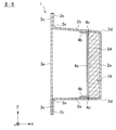
- FIG. 5 is a cross-sectional view in a cross section orthogonal to the Z-axis direction of an example of the frame 1 according to the present embodiment.
- the cross-sectional view shown in FIG. 5 corresponds to the cross-sectional view of the hollow member 10 taken along the line I-I shown in FIG.
- the hollow member 10 has two bends 6A and 6B.
- the bending portion 6A bends in the direction of the bottom wall portion 2a so that the bottom wall portion 2a bends inward.
- the bending portion 6B bends in the direction of the ceiling wall portion 3a so that the ceiling wall portion 3a is bent inside.
- These bent portions 6A, 6B correspond to bending induction portions in the frame 1.
- the filling members 5 (5A to 5D) according to the present embodiment are disposed in close contact with the main surface 4a of the reinforcement 4, respectively.
- the filling members 5A and 5B are provided at a portion facing the bottom wall 2a.
- the filling members 5C and 5D are provided in the part facing the top wall part 3a.
- the filling member 5 is in close contact with the inner surface of the bottom wall 2a or the top wall 3a, and is disposed adjacent to or separated from the bending portion 6A or the bending portion 6B in the longitudinal direction.
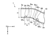
- the filling members 5A and 5B are not disposed in the portion 2x of the bottom wall portion 2a of the bending portion 6A, and adhere to the inner surface of the portion separated from the bending portion 6A in the longitudinal direction of the bottom wall portion 2a. It is arranged.
- the filling members 5C and 5D are not disposed in the portion 3x of the top wall portion 3a in the bending portion 6B, and are disposed in close contact with the inner surface of the portion separated from the bending portion 6B in the longitudinal direction of the top wall portion 3a. .
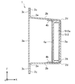
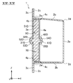
- FIG. 6 and 7 are cross-sectional views taken along the lines II-II and III-III of the frame 1 shown in FIG.
- the filling member 5A is disposed in close contact with the main surface 4a in a space 7A formed by the bottom wall 2a, the main surface 4a, and the pair of side walls 2b.
- the filling member 5A should just be arrange
- the filling member 5A may not necessarily be disposed on the space 7A side. More specifically, the filling member 5A may be disposed in close contact with the main surface 4a in the space opposite to the space 7A with respect to the reinforcement 4.
- the arrangement of the filling members 5B is the same as the arrangement of the filling members 5A described with reference to FIG. Further, as shown in FIG. 7, the filling member 5D is disposed in close contact with the main surface 4a in a space 7B formed by the top wall 3a, the main surface 4a, and the pair of side walls 2b. .
- the filling member 5D may not necessarily be disposed in the space 7B as in the example of the filling member 5A. More specifically, the filling member 5D may be disposed in close contact with the main surface portion 4a in the space opposite to the space 7B with respect to the reinforcement 4.
- the arrangement of the filling members 5C is the same as the arrangement of the filling members 5D described with reference to FIG.
- the filling members 5A and 5B are disposed in close contact with the main surface 4a of the reinforcement 4.
- the close contact (preferably, adhesion) of the filling members 5A and 5B to the main surface portion 4a increases the resistance to the out-of-plane deformation of the main surface portion 4a.
- the reinforcement 4 can suppress the deformation of the side wall portion 2b due to the input of the collision load, the deformation of the closed cross section of the hollow member 10 is also suppressed. Therefore, the collision safety performance of the frame 1 can be more reliably exhibited.
- filling members 5A and 5B are not disposed in portion 2x of bottom wall portion 2a in bending portion 6A, and are portions separated from bending portion 6A in the longitudinal direction of bottom wall portion 2a. It is disposed in intimate contact (preferably adhesive) on the inner surface. Because the filling members 5A and 5B are not disposed in the portion 2x of the bottom wall 2a in the bend 6A, the resistance to out-of-plane deformation of the portion 2x of the bottom wall 2a in the bend 6A remains low. That is, the bending stiffness in the bending portion 6A remains low. As a result, when a collision load is input to the frame 1, bending deformation can be reliably generated in the bending portion 6A.
- filling members 5A and 5B are disposed in close contact with the inner surface of a portion separated from bent portion 6A in the longitudinal direction of bottom wall portion 2a, thereby a bottom wall in the portion where filling members 5A and 5B are arranged.
- the resistance to the out-of-plane deformation of the portion 2a is increased.
- the bottom wall portion in the portion where the filling members 5A and 5B are disposed which is generated along with the out-of-plane deformation of the bending portion 6A.
- the out-of-plane deformation of 2a can be suppressed. Therefore, the cross-sectional deformation of the closed cross section of the hollow member 10 is suppressed by the filling members 5A and 5B. Therefore, the collision safety performance of the frame 1 can be further enhanced.
- connection means that the filling members 5A and 5B are disposed in close contact with each other across the main surface portion 4a and the bottom wall portion 2a.
- connection means that the filling members 5A and 5B are disposed in close contact with each other across the main surface portion 4a and the bottom wall portion 2a.
- the filling members 5A and 5B are disposed in close contact with the reinforcement 4 and the side wall portion 2b continuously. That is, the filling members 5A and 5B are disposed in close contact with the inside of the connection portion 4c connecting the main surface portion 4a and the side wall portion 2b.
- a collision load to the frame 1 is input and bending occurs in the bending portion 6, high stress occurs in the connection portion 4c, and plastic deformation locally occurs in the connection portion 4c.
- filling members 5A and 5B in close contact (preferably, adhering) to connecting portion 4c, it is possible to suppress local plastic deformation that occurs in connecting portion 4c. Thereby, the collision safety performance of the frame 1 can be more effectively enhanced.
- the filling members 5A and 5B are disposed in close contact with the bottom wall 2a and the side wall 2b in a continuous manner. That is, the filling members 5A and 5B are disposed in close contact with the inner side of the ridge portion 2d. Similar to the plastic deformation at the connecting portion 4c described above, when a collision load on the frame 1 is input and bending occurs at the bending portion 6A, plastic deformation locally occurs at the ridge portion 2d. Therefore, local plastic deformation which occurs in the ridge portion 2d can be suppressed by arranging the filling members 5A and 5B in close contact (preferably bonding) at the positions. Thereby, the collision safety performance of the frame 1 can be more effectively enhanced.
- the filling members 5A and 5B are disposed in intimate contact with the inside of all the ridge portions 2d and the connecting portions 4c. If the filling members 5A and 5B are disposed inside of at least one of the ridge portion 2d and the connection portion 4c, the improvement of the collision safety performance is exhibited.
- the Young's modulus of the filling member 5 is higher, the effect of suppressing the plastic deformation described above by the filling member 5 is enhanced.
- the place where the cross-sectional deformation is to be suppressed can be limited to a portion adjacent to or separated from the bending portion 6. For this reason, the place which should arrange the filling member 5 can also be limited in anticipation of the place which carries out cross-sectional deformation. That is, in the present embodiment, it is possible to reduce the weight increase associated with the increase in the Young's modulus of the filling member 5. Thus, in this embodiment, it is possible to improve the collision safety performance with high mass efficiency.
- the reinforcement 4 is provided inside the bending portion 6 which is a bending induction portion, and the filling member 5 is disposed in close contact with the reinforcement 4.
- the reinforcement 4 since the cross-sectional shape of the hollow member 10 is maintained by the reinforcement 4, the cross-sectional deformation of the hollow member 10 can be suppressed. Therefore, even when the plate thickness of the hollow member 10 and the reinforcement 4 is reduced in order to reduce the weight of the vehicle body, the collision safety performance of the frame 1 can be maintained.
- the reinforcement 4 shown in FIG. 5 is formed of one member and is provided to face each of the bottom wall portion 2a and the top wall portion 3a of the bending portion 6, but the present invention is not limited thereto. It is not limited to.
- a plurality of reinforcements 4 may be provided to be opposed to the bottom wall 2a or the top wall 3a in the bending induction portion such as the bending portion 6 or the like.
- the reinforcement 4 may be provided entirely along the longitudinal direction of the hollow member 10. That is, the position and length of the reinforcement 4 in the longitudinal direction of the hollow member 10 are not particularly limited as long as the reinforcement 4 is provided inside the bending induction portion.
- the filling member 5 is in close contact with the hollow member 10, arranged around the bending portion 6 which is a bending induction portion, and the filling member 5 is not arranged in the bending portion 6
- the filling member 510 disposed in close contact with the reinforcement 4 suppresses out-of-plane deformation of the reinforcement 4. If the out-of-plane deformation of the reinforcement 4 can be suppressed, the out-of-plane deformation of the wall (for example, the side wall 2 b) to which the reinforcement 4 is connected can be suppressed. As a result, the cross-sectional deformation of the hollow member 10 can be suppressed.
- FIG. 8 is a cross-sectional view of the frame 1 for explaining a first arrangement example of the filling member according to the present embodiment.
- the cross sectional view shown in FIG. 8 corresponds to the cross section of the frame 1 taken along the line II-II of the frame 1 shown in FIG.
- the filling member 510 is disposed in close contact (preferably adhered) to the central portion of the surface of the main surface 4 a facing the bottom wall 2 a.
- the resistance to the out-of-plane deformation of the main surface portion 4a can be increased. That is, the out-of-plane deformation of the reinforcement 4 can be suppressed and the buckling of the reinforcement 4 can be suppressed also by closely arranging the filling member 510 only on a part of the main surface portion 4 a. That is, the effect of suppressing the cross-sectional deformation of the hollow member 10 can be sufficiently obtained. Therefore, if it is possible to ensure the required collision safety performance, as shown in FIG.
- the filling member 510 may be arranged only on a part of the main surface 4a. As a result, since the filling amount of the filling member 510 is reduced, the cost of the filling member 510 and the weight of the frame 1 can be kept low.
- the arrangement position of the filling member 510 is not restricted to the side facing the bottom wall part 2a of the main surface part 4a.
- the filling member 510 shown in FIG. 8 may be provided on the main surface 4a on the side facing the top wall 3a. That is, as long as the filling member 510 is disposed in close contact with the reinforcement 4, the arrangement surface of the main surface 4 a of the filling member 510 is not particularly limited.
- the filling member 511 connects the reinforcement 4 and the wall (for example, the bottom wall 2 a) opposed to the reinforcement 4. Since the walls facing the reinforcement 4 and the reinforcement 4 via the filling member 511 restrain each other, out-of-plane deformation of the reinforcement 4 and the wall facing the reinforcement 4 can be suppressed. Furthermore, since the out-of-plane deformation of the reinforcement 4 can be suppressed, the out-of-plane deformation of the wall portion to which the reinforcement 4 is connected can also be suppressed. As a result, the cross-sectional deformation of the hollow member 10 can be suppressed.
- FIG. 9 is a cross-sectional view of the frame 1 for explaining a second arrangement example of the filling member according to the present embodiment.
- the cross sectional view shown in FIG. 9 corresponds to the cross section of the frame 1 taken along the line II-II of the frame 1 shown in FIG.
- the filling member 511 is disposed in close contact (preferably adhered) to each part so as to connect the central part of the main surface 4a and the central part of the bottom wall 2a.
- the out-of-plane deformation of the reinforcement 4 and the bottom wall 2a can be more effectively suppressed.
- the filling member 511 connects a part of the main surface 4a and a part of the bottom wall 2a, the effect of suppressing the cross-sectional deformation of the hollow member 10 is sufficiently obtained. be able to. Therefore, if it is possible to secure the required collision safety performance, as shown in FIG.
- filling member 511 is arranged to connect only a part of main surface 4a and bottom wall 2a. It is also good. As a result, the filling amount of the filling member 511 is reduced, so that the cost of the filling member 511 and the weight of the frame 1 can be reduced.
- the arrangement position of the filling member 511 is not limited to between the main surface portion 4a and the bottom wall portion 2a.
- the filling member 511 shown in FIG. 9 may be disposed between the main surface portion 4a and the top wall portion 3a, and may connect the main surface portion 4a and the top wall portion 3a.
- the filling member 511 may connect any one of the side wall 2b and the main surface 4a. That is, as long as the filling member 511 is disposed in close contact with the reinforcement 4, the part to be connected by the filling member 511 is not particularly limited.
- the arrangement position in the Z-axis direction of the main surface portion 4a (and the bottom wall portion 2a) of the filling member 5 shown in the first arrangement example and the second arrangement example is not particularly limited. However, it is preferable that the filling member 5 be disposed in close contact with the central portion of the main surface 4a where the amount of deflection of the main surface 4a receiving the bending moment is the largest. Furthermore, the width of the filling member 5 on the main surface portion 4a is preferably 20% or more of the width of the main surface portion. It is more desirable if it is 30% or more. Thereby, it is possible to prevent the collision energy from being biased to the reinforcement 4 by the elastic deformation of the reinforcement 4. When the collision energy is biased to the reinforcement 4, energy absorption by bending at the collision is hindered.
- the filling member 5 may not necessarily be disposed so as to closely fill the space 7A. If the filling member 5 is disposed in close contact with at least the major surface 4 a of the reinforcement 4, the effect of suppressing the cross-sectional deformation of the hollow member due to the reinforcement 4 is exhibited.
- the filling amount and the arrangement position of the filling member 5 in the space 7A can be appropriately adjusted based on the required collision safety performance of the frame 1 and the weight of the frame 1, the filling cost of the filling member 5, and the like.
- the filling member 5 may not necessarily be provided in the space 7A. That is, the filling member 5 may be disposed in the space of the hollow member 10 on the side different from the space 7A.
- the filling member 512 connects the reinforcement 4 and the wall portion to which the reinforcement 4 is connected. Since the reinforcement 4 and the wall to which the reinforcement 4 is connected are restrained by the filling member 512, the angle formed by the reinforcement 4 and the wall to which the reinforcement 4 is connected is fixed. As a result, the cross-sectional deformation of the hollow member 10 can be suppressed.
- FIG. 10 is a cross-sectional view of the frame 1 for explaining a third arrangement example of the filling member according to the present embodiment.
- the cross sectional view shown in FIG. 10 corresponds to the cross section of the frame 1 taken along the line II-II of the frame 1 shown in FIG.
- the filling member 512 includes the main surface 4a, the bottom wall 2a, and the pair of spaces 7A formed by being surrounded by the main surface 4a, the bottom wall 2a, and the pair of side walls 2b. It is arrange
- Second embodiment the resin material is disposed in close contact with the inner surface of at least one of the bottom wall or the top wall of the metal member, and in the longitudinal direction adjacent to or apart from the bending inducing portion.
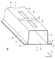
- FIG. 11 is a perspective view showing a schematic configuration of an example of a frame 1 according to a second embodiment of the present invention.
- a frame 1 according to the present embodiment includes a first structural member 2, a second structural member 3, and filling members 5 (5A to 5D).
- the hollow member 10 according to the present embodiment is formed by the first structural member 2 and the second structural member 3.
- the configuration of the frame 1 shown in FIG. 11 is the same as that described in the first embodiment with reference to FIGS. 2 to 4 except for the point having no reinforcement 4 and the arrangement of the filling member 5.
- frame 1 which concerns on this embodiment is demonstrated.
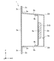
- FIG. 12 is a cross-sectional view showing a cross section orthogonal to the Z-axis direction of an example of the frame 1 according to the present embodiment.
- the cross-sectional view shown in FIG. 12 corresponds to the cross-sectional view of the hollow member 10 taken along the line IV-IV shown in FIG.
- the hollow member 10 is provided with bending portions 6A and 6B.
- the bending portion 6A bends in the direction in which the bottom wall portion 2a bends inward.
- the bending portion 6B bends in a direction in which the top wall portion 3a bends inward.
- the filling member 5 is in close contact with the inner surface of the bottom wall 2a or the top wall 3a, and is disposed adjacent to or separated from the bending portion 6A or the bending portion 6B in the longitudinal direction.
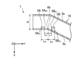
- the filling members 5A and 5B are not disposed in the portion 2x of the bottom wall portion 2a provided with the bending portion 6A, and are arranged apart from the bending portion 6A in the longitudinal direction.
- filling members 5C and 5D are not disposed in portion 3x provided with bent portion 6B in top wall portion 3a, and are spaced apart from bent portion 6B in the longitudinal direction. Be done.
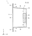
- FIG. 13 is a cross-sectional view taken along the line VV of the frame 1 shown in FIG.
- FIG. 14 is a cross-sectional view taken along the line VI-VI of the frame 1 shown in FIG.
- the filling member 5A is disposed in close contact (preferably, adhered) to the inner surface of the bottom wall 2a.
- the filling member 5A is disposed in intimate contact with the inner surface of the central portion of the bottom wall 2a.
- the arrangement of the filling member 5B is the same as the arrangement of the filling member 5A described with reference to FIG.
- the filling member 5D is disposed in close contact with the inner surface of the top wall 3a.
- the arrangement of the filling members 5C is the same as the arrangement of the filling members 5D described with reference to FIG.
- filling members 5A and 5B are not disposed on portion 2x of bottom wall 2a of bent portion 6A, but on the inner surface of the portion of bottom wall 2a spaced apart from bent portion 6A in the longitudinal direction. It is arranged in close contact (preferably adhesive). Because the filling members 5A and 5B are not disposed in the portion 2x of the bottom wall 2a in the bend 6A, the resistance to out-of-plane deformation of the portion 2x of the bottom wall 2a in the bend 6A remains low. That is, the bending stiffness in the bending portion 6A remains low. As a result, when a collision load is input to the frame 1, bending deformation can be reliably generated in the bending portion 6A.
- the filling members 5A and 5B are disposed in close contact with the inner surface of the central portion of the portion separated from the bending portion 6A in the longitudinal direction of the bottom wall portion 2a.
- the collision load when the collision load is input to the frame 1, it is possible to suppress the out-of-plane deformation of the hollow member 10 in the portion where the filling members 5A and 5B are disposed. Thereby, since the cross-sectional deformation
- the thickness a in the X-axis direction of the filling members 5A and 5B is not particularly limited, and the thickness a is appropriately set according to the load resistance performance and the weight required for the frame 1.
- a plate material such as reinforcement (not shown) may be provided inside the hollow member 10.
- the distance b 1 and b 2 from the side wall portion defining the position of the filling member 5A and 5B there is no particular limitation on the distance b 1 and b 2 from the side wall portion defining the position of the filling member 5A and 5B.
- the filling members 5A and 5B in close contact with the inner surface of the central portion of the bottom wall 2a, it is possible to efficiently suppress the out-of-plane deformation of the bottom wall 2a.
- the width of the filling members 5A and 5B on the bottom wall 2a is preferably 20% or more of the width of the bottom wall 2a. It is more desirable if it is 30% or more. Further, it is preferable that the distances b 1 and b 2 be the same value. The size of the distance b 1 and b 2 are determined according to the thickness of the X-axis direction of the filling member 5A and 5B are appropriately set according to the load carrying capacity and weight are required to frame 1.
- filling members 5C and 5D are disposed on top wall 3a.
- Filling members 5C and 5D are the same as filling members 5A and 5B described with reference to FIGS. 12 and 13 except that they are disposed on top wall portion 3a.
- the width of the filling members 5C and 5D on the top wall 3a is preferably 20% or more of the width of the top wall 3a in the closed cross section. It is more desirable if it is 30% or more.
- close contact means being disposed in contact without a gap.
- adhesions in particular, adhesions which restrain each other are most preferable. Even when they do not restrain one another, the effect of suppressing the out-of-plane deformation of at least one of the wall portions forming the hollow member 10 is exhibited.
- FIGS. 116 and 117 it is assumed that a change in cross-sectional shape as shown in FIGS. 116 and 117 occurs in the frame 1 according to the present embodiment.
- the filling member 5 is adhered to the inner surface of at least one of the bottom wall portion 2a or the top wall portion 3a, when the bottom wall portion 2a or the top wall portion 3a is deformed out of plane, the filling member 5 is also out of plane of the inner surface.
- the effect of suppressing the out-of-plane deformation of the bottom wall portion 2a or the top wall portion 3a by the filling member 5 is significantly exhibited.
- the filling member 5 and the inner surface of at least one of the bottom wall portion 2a or the top wall portion 3a are disposed in close contact with each other without being restricted to each other, the bottom wall portion 2a or the top wall portion 3a is deformed out of plane
- the filling member 5 and the inner surface are partially separated.
- at least a part of the filling member 5 is in contact with the inner surface.
- the Young's modulus of the filling member 5 is higher, the effect of suppressing the plastic deformation described above by the filling member 5 is enhanced.
- the place where the cross-sectional deformation is to be suppressed can be limited to a portion adjacent to or separated from the bending portion 6. For this reason, the place which should arrange the filling member 5 can also be limited in anticipation of the place which carries out cross-sectional deformation. That is, in the present embodiment, it is possible to reduce the weight increase associated with the increase in the Young's modulus of the filling member 5. Thus, in this embodiment, it is possible to improve the collision safety performance with high mass efficiency.
- the arrangement of the filling members 5A and 5B, and the operation and effect of the arrangement have been described.
- the case where filling members 5A and 5B are arranged apart from bending portion 6A in the longitudinal direction has been described above, the case where filling members 5A and 5B are arranged adjacent to bending portion 6A in the longitudinal direction
- the filling members 5A and 5B are connected and partially around the bending portion 6A in a range overlapping with the bending portion 6A. Even when the amount of the filling member 5 per longitudinal length to be arranged in comparison is small, the above-described action and effect are similarly exhibited.
- the functions and effects described above are similarly exerted by the filling members 5C and 5D disposed adjacent to or apart from the bending portion 6B as shown in FIGS. 12 and 14.
- the filling member 5 is in close contact with the inner surface of the bottom wall portion 2a or the top wall portion 3a, and is disposed around the bending portion 6 which is a bending induction portion. There is a region where the filling member 5 is not disposed at the bending portion 6 or a region where the amount of the filling member 5 per longitudinal length is smaller than that at the periphery of the bending portion 6 in a part of the range overlapping the bending portion 6 is there. With such a configuration, bending stiffness at the bending portion 6 can be kept low. Thus, when a collision load is input to the frame 1, bending deformation can be reliably generated in the bending portion 6.
- the filling member connects the end of the side wall 2b and the bottom wall 2a or the top wall 3a. That is, the filling member is disposed adjacent to the ridge 2d or the ridge 2e.
- the filling member suppresses the change in the angle between the side wall 2b and the bottom wall 2a or the top wall 3a. That is, the filling member suppresses deformation of the ridge 2d or the ridge 2e. As a result, the cross-sectional deformation of the hollow member 10 can be suppressed.
- FIG. 15 is a cross-sectional view of the frame 1 for explaining a first arrangement example of the filling member according to the present embodiment.
- the cross-sectional view shown in FIG. 15 corresponds to the cross section of the frame 1 taken along the line VV of the frame 1 shown in FIG.
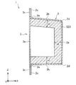
- the filling member 520 is arranged in close contact (preferably, adhered) with the side wall 2 b and the bottom wall 2 a continuously. That is, the filling member 520 is disposed in close contact with the inner side of the ridge portion 2 d.
- plastic deformation locally occurs in the ridge portion 2d.
- the plastic deformation accelerates the falling of the side wall 2b in the out-of-plane direction. Therefore, the local plastic deformation which arises in ridgeline part 2d can be controlled by closely arranging filling member 520 in the position concerned. Thereby, it is possible to suppress the falling of the side wall portion 2b in the out-of-plane direction. Therefore, the cross-sectional deformation of the frame 1 can be suppressed more effectively.
- the thickness a of the filling member 520 is appropriately set in accordance with the load-bearing performance and the weight required for the frame 1.
- the arrangement of the filling members shown in FIG. 15 can be similarly applied to the cross section of the frame 1 taken along the line VI-VI of the frame 1 shown in FIG.
- the filling member 520 is disposed in intimate contact with the inner surface of the ceiling wall 3a and the inside of the ridge line 2e.
- FIG. 16 is a cross-sectional view of the frame 1 for explaining a second arrangement example of the filling member according to the present embodiment.
- the cross sectional view shown in FIG. 16 corresponds to the cross section of the frame 1 taken along the line VV of the frame 1 shown in FIG.
- the filling members 521a and 521b according to this arrangement example are arranged in close contact (preferably, adhesively) on the inner side of each of the ridge portions 2d.
- This arrangement it is possible to suppress the local plastic deformation occurring in the ridge portion 2 d. Thereby, it is possible to reduce the falling of the side wall 2b in the out-of-plane direction. Therefore, cross-sectional deformation of the frame 1 can be suppressed.
- the cross-sectional deformation of the frame 1 can be reduced with little increase in the weight of the frame 1. It can be suppressed.
- FIG. 17 is a cross-sectional view of the frame 1 for explaining a third arrangement example of the filling member according to the present embodiment.
- the cross sectional view shown in FIG. 17 corresponds to the cross section of the frame 1 taken along the line VV of the frame 1 shown in FIG.
- the filling member 521c according to this arrangement example is arranged in close contact locally on one inner side of the ridge portion 2d. Thereby, the local plastic deformation which arises in ridgeline part 2d in which filling member 521c is arranged can be controlled. Further, since the filling amount of the filling member can be reduced, the weight of the frame 1 can be increased.
- the filling member shown in FIGS. 16 and 17 not only the out-of-plane deformation of the bottom wall portion 2a but also the local plastic deformation of the ridge portion 2d can be suppressed.
- whether the filling member is provided inside one or both of the ridge portions 2 d is preferably determined according to the collision safety performance and weight required for the frame 1.
- the thickness a (a 1 , a 2 ) in the Z-axis direction and the thickness c (c 1 , c 2 ) in the X-axis direction of the filling members 521 a, 521 b and 521 c are appropriately set.
- the filling members may be separately and closely disposed on the inner surface of the central portion of the bottom wall portion 2a and the inside of the ridge portion 2d. If each of the filling members is disposed in close contact with the inner surface of the central portion of the bottom wall portion 2a and the inside of the ridge portion 2d, the effect of suppressing the cross-sectional deformation of the frame 1 can be sufficiently obtained.
- the arrangement of the filling members shown in FIGS. 16 and 17 can be similarly applied to the cross section of the frame 1 taken along the line VI-VI of the frame 1 shown in FIG.
- the filling members 521a to 521c are disposed in close contact with the inner side of the ridge portion 2e.
- the filling member may be disposed in close contact with the inner surface of the side wall portion 2b as well as the inner side of the ridge line portion 2d.
- FIG. 18 and FIG. 19 are cross-sectional views of the frame 1 for explaining each modification of the second arrangement example and the third arrangement example of the filling member according to the present embodiment. As shown in FIGS. 18 and 19, the filling members 522a, 522b and 522c may be disposed in close contact with the inner surface of the side wall 2b as well as the inside of the ridge line 2d. Furthermore, the filling members 522a, 522b and 522c may be disposed in close contact with the inside of the ridge portion 2e.
- the load resistance performance of the frame 1 can be made equal to or higher than the arrangement example shown in FIGS. 16 and 17.
- the thickness a (a 1 , a 2 ) of the filling members 522 a, 522 b and 522 c is appropriately set according to the load-bearing performance and weight required for the frame 1.
- FIG. 20 is a cross-sectional view of the frame 1 for explaining a fourth arrangement example of the filling member according to the present embodiment.
- the cross sectional view shown in FIG. 20 corresponds to the cross section of the frame 1 taken along the line VV of the frame 1 shown in FIG.
- the filling member 523 As shown in FIG. 20, the filling member 523 according to this arrangement example is arranged in close contact (preferably, adhesively) continuously with the bottom wall 2a and the inner surfaces of the pair of side walls 2b. In the side wall portion 2b, the frame 1 is easily bent to cause an out-of-plane direction to fall. According to the arrangement shown in FIG. 20, since the filling member 523 is disposed in close contact with the inner surface of the side wall 2b, the filling member 523 can suppress the out-of-plane deformation of the side wall 2b.
- the filling member 523 shown in FIG. 20 is disposed continuously in close contact with the pair of side wall portions 2b and the bottom wall portion 2a
- the present invention is not limited to this example.
- the filling members 523 may be separately and closely disposed on the inner surfaces of the pair of side wall portions 2b and the bottom wall portion 2a.
- the filling member 523 may be disposed in close contact with any one of the pair of side wall portions 2 b and the bottom wall portion 2 a continuously. That is, in the cross section orthogonal to the Y-axis direction, the filling member 523 may be provided in an L shape.
- the filling member 523 is provided on either of the pair of side wall portions 2b and the bottom wall portion 2a, not only the load bearing performance of the frame 1 but also the absorption characteristics of the collision energy of the frame 1 can be improved. it can.
- the arrangement position and filling amount of the filling member can be appropriately set according to the collision safety performance and weight required for the frame 1. Also, the thicknesses a 1 , a 2 and a 3 of the filling member 523 shown in FIG. 20 may be set appropriately.
- the arrangement of the filling members shown in FIG. 20 can be similarly applied to the cross section of the frame 1 taken along the line VI-VI of the frame 1 shown in FIG.
- the filling member 523 is disposed continuously in close contact with the pair of side wall portions 2 b and the top wall portion 3 a.
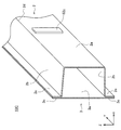
- FIG. 21 is a perspective view showing a schematic configuration of an example of a frame 1 according to a third embodiment of the present invention.
- a frame 1 according to the present embodiment includes a first structural member 2, a second structural member 3, and filling members 5 (5A to 5D).
- the hollow member 10 according to the present embodiment is formed by the first structural member 2 and the second structural member 3.
- the configuration of the frame 1 shown in FIG. 21 is the same as that described in the first embodiment with reference to FIGS. 2 to 4 except for the point having no reinforcement 4 and the arrangement of the filling member 5.
- frame 1 which concerns on this embodiment is demonstrated.
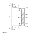
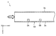
- FIG. 22 is a cross-sectional view showing a cross section orthogonal to the Z-axis direction of an example of the frame 1 according to the present embodiment.
- the cross-sectional view shown in FIG. 22 corresponds to the cross-sectional view of the hollow member 10 along the line VII-VII shown in FIG.
- bends 6A and 6B are provided.
- the bending portion 6A bends in the direction in which the bottom wall portion 2a bends inward.
- the bending portion 6B bends in a direction in which the top wall portion 3a bends inward.
- the filling member 5 is in close contact with the inner surface of the side wall 2b, and is disposed adjacent to or separated from the bending portion 6A or the bending portion 6B in the longitudinal direction.
- the filling members 5A and 5B are not disposed in the portion 2x of the side wall 2b provided with the bending portion 6A, and are arranged apart from the bending portion 6A in the longitudinal direction.
- filling members 5C and 5D are not disposed in portion 2y provided with bent portion 6B in side wall portion 2b, and are disposed apart from bent portion 6B in the longitudinal direction. Ru.
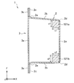
- FIG. 23 is a cross-sectional view taken along line VIII-VIII of frame 1 shown in FIG.
- the filling member 5A is disposed in close contact with (preferably adhered to) the inner surface of the side wall 2b.
- the arrangement of the filling members 5B is the same as the arrangement of the filling members 5A described with reference to FIG.
- the filling member 5D is disposed in close contact with the inner surface of the side wall portion 2b in the cross section taken along the line IX-IX of the frame 1 shown in FIG.
- the arrangement of the filling members 5C is the same as the arrangement of the filling members 5D.
- filling members 5A and 5B are not disposed on portion 2x of side wall portion 2b in bending portion 6A, and are in intimate contact with the inner surface of the portion separated from bending portion 6A in the longitudinal direction of side wall portion 2b ( Preferably, it is arrange
- filling members 5A and 5B are disposed in close contact with the inner surface of a portion separated from bent portion 6A in the longitudinal direction of side wall portion 2b.
- the filling members 5A and 5B restrain the side wall 2b, out-of-plane deformation of the side wall 2b can be suppressed. That is, in the bending deformation of the frame 1 when the collision load is input to the frame 1, the side wall portion 2b is produced along with the deformation of the bending portion 6A in the out-of-plane direction of the portion where the filling members 5A and 5B are arranged. Fall can be suppressed.
- the cross-sectional deformation of the frame 1 is suppressed even after the bending deformation of the frame 1, the absorption characteristic of the collision energy of the frame 1 can be enhanced.
- the arrangement of the filling members 5A and 5B is limited to a portion that contributes to shock absorption, the hollow member does not become heavy.
- the filling members 5A and 5B are disposed in close contact with the side wall 2b and the bottom wall 2a in a continuous manner. That is, the filling members 5A and 5B are disposed in close contact with the inner side of the ridge portion 2d.
- plastic deformation locally occurs in the ridge portion 2d.
- the plastic deformation accelerates the falling of the side wall 2b in the out-of-plane direction. Therefore, local plastic deformation occurring in ridge portion 2d can be suppressed by closely arranging filling members 5A and 5B at such positions. Thereby, it is possible to suppress the falling of the side wall portion 2b in the out-of-plane direction. Therefore, the collision energy absorption characteristic of the frame 1 can be more effectively enhanced.
- the filling members 5A and 5B may be disposed in close contact with the side wall 2b and the top wall 3a continuously. Thereby, the local plastic deformation which arises in ridgeline part 2e can be controlled. As a result, the cross-sectional deformation of the hollow member 10 can be suppressed, and the collision safety performance of the frame 1 can be further enhanced.
- the filling members 5A and 5B are disposed in close contact with the inside of at least one of the ridges 2d and 2e as shown in FIG. At this time, the bending portion 6A bends the bottom wall portion 2a in a bending inner direction.
- the filling members 5A and 5B be disposed at least in close contact with the inner side of the ridge line portion 2d existing at the boundary between the bottom wall portion 2a and the side wall portion 2b.
- the filling members 5A and 5B are disposed on the inner surface of the upper side wall 2b as viewed in FIG. 23, but are disposed on the inner surface of the lower side wall 2b. It may be done. Further, the thickness a of the filling members 5A and 5B is not particularly limited, and the thickness a is appropriately set according to the absorption characteristics and the weight of the collision energy required for the frame 1. In order to control the thickness a of the filling members 5A and 5B, for example, a plate material such as reinforcement (not shown) may be provided inside the hollow member 10.
- close contact means being disposed in contact without a gap.
- adhesions in particular, adhesions which restrain each other are most preferable. Even when they do not restrain one another, the effect of suppressing the out-of-plane deformation of at least one of the wall portions forming the hollow member 10 is exhibited.
- FIGS. 116 and 117 it is assumed that a change in cross-sectional shape as shown in FIGS. 116 and 117 occurs in the frame 1 according to the present embodiment.
- the filling member 5 In the case where the filling member 5 is adhered to the inner surface of the side wall 2b, when the side wall 2b is out-of-plane deformed, the filling member 5 also follows the out-of-plane deformation of the inner surface.
- the effect of suppressing the out-of-plane deformation of the side wall portion 2 b by the filling member 5 is significantly exhibited.
- the side wall portion 2b may be partially separated from the inner surface when the side wall portion 2b is deformed out of plane. Exists.
- the inner surface is deformed out of plane, at least a part of the filling member 5 is in contact with the inner surface. Therefore, even in the state where the filling member 5 and the inner surface are in close contact with each other without being restricted to each other, the effect of suppressing the out-of-plane deformation of the side wall portion 2b by the filling member 5 is sufficiently exhibited.
- the Young's modulus of the filling member 5 is higher, the effect of suppressing the plastic deformation described above by the filling member 5 is enhanced.
- the place where the cross-sectional deformation is to be suppressed can be limited to a portion adjacent to or separated from the bending portion 6. For this reason, the place which should arrange the filling member 5 can also be limited in anticipation of the place which carries out cross-sectional deformation. That is, in the present embodiment, it is possible to reduce the weight increase associated with the increase in the Young's modulus of the filling member 5. Thus, in this embodiment, it is possible to improve the collision safety performance with high mass efficiency.
- the filling member 5 is in close contact with the inner surface of the side wall 2b, and is disposed around the bending portion 6 which is a bending induction portion. There is a region where 5 is not disposed, or a region overlapping with the bending portion 6, there is a region where the amount of the filling member 5 per longitudinal length arranged is smaller than that of the periphery of the bending portion 6. With such a configuration, bending stiffness at the bending portion 6 can be kept low. As a result, when a collision load is input to the frame 1, bending deformation can be reliably generated in the bending portion 6.
- out-of-plane deformation of the side wall 2b is suppressed by the filling member 530a or 531a disposed in close contact with the side wall 2b.
- cross-sectional deformation of the frame 1 can be suppressed.
- FIG. 24 is a cross-sectional view of the frame 1 for explaining a first arrangement example of the filling member according to the present embodiment.
- the cross sectional view shown in FIG. 24 corresponds to the cross section of the frame 1 taken along the line VIII-VIII of the frame 1 shown in FIG.
- the filling members 530a and 530b according to this arrangement example are arranged in close contact (preferably adhered) to the inner surfaces of the pair of side wall portions 2b.
- this arrangement it is possible to suppress the out-of-plane deformation of each of the side wall portions 2b and prevent the side walls 2b from falling in the out-of-plane direction. That is, since deformation of the cross section of the frame 1 can be suppressed more reliably than arranging one filling member for one side wall portion 2 b, the absorption characteristic of the collision energy of the frame 1 can be further improved. it can.
- the filling members 530a and 530b are disposed in intimate contact with the insides of the ridge portions 2d and 2e, respectively. Therefore, plastic deformation in each ridge line portion can be suppressed, and sectional deformation of the frame 1 can be further suppressed.
- the filling members 530 a and 530 b are provided on the frame 1, the overall weight of the frame 1 is increased. Therefore, it is preferable to determine whether the filling member is provided on the inner surface of one or both of the side wall portions 2b according to the collision safety performance and the weight required for the frame 1. Further, the thickness a 2 thick a 1 and 530b of the filling member 530a is appropriately set.
- the arrangement of the filling members shown in FIG. 24 can be similarly applied to the cross section of the frame 1 taken along the line IX-IX of the frame 1 shown in FIG.
- FIG. 25 is a cross-sectional view of the frame 1 for explaining a second arrangement example of the filling member according to the present embodiment.
- the cross-sectional view shown in FIG. 25 corresponds to the cross section of the frame 1 in VIII-VIII of the frame 1 shown in FIG.
- the filling members 531a and 531b according to the present arrangement example are disposed in close contact (preferably, adhered) to the central portions of the inner surfaces of the pair of side wall portions 2b.
- the out-of-plane deformation of the side wall 2b is suppressed, and the side wall 2b falls in the out-of-plane direction. Can be prevented locally. Therefore, the absorption characteristic of the collision energy of the frame 1 can be improved.
- the filling members 531a and 531b are disposed in close contact with the inner surfaces of the side wall portions 2b, but the filling members are disposed only on one of the inner surfaces of the side wall portions 2b. May be Whether the filling member is provided on the inner surface of one or both of the side walls 2b is preferably determined in accordance with the collision safety performance and weight required for the frame 1.
- the filling member thickness a 1 and 531b of the wall thickness a 2 of 531a, the distance from the top wall 3a of the filling member 531a on the side wall 2b b 1 and b 3, and the distance b 2 from the bottom wall portion 2a And b 4 can be set appropriately.
- the falling of the side wall portion 2b in the out-of-plane direction is caused by the plastic deformation of the ridge portion 2d (2e). Therefore, it is preferable that the filling member 5 disposed in close contact with the inner surface of the side wall portion 2b be disposed in close contact also with the inside of the ridge portion 2d (2e). Thereby, the suppression effect of the cross-sectional deformation of the flame
- the arrangement of the filling members shown in FIG. 25 can be similarly applied to the cross section of the frame 1 taken along the line IX-IX of the frame 1 shown in FIG.
- the filling member is arranged in close contact with the side wall 2b and the bottom wall 2a connected with the side wall 2b. Since the ridge 2d is restrained by the filling member, the deformation of the ridge 2d is suppressed. As a result, cross-sectional deformation of the frame 1 can be suppressed.
- FIG. 26 is a cross-sectional view of the frame 1 for explaining a third arrangement example of the filling member according to the present embodiment.
- the cross-sectional view shown in FIG. 26 corresponds to the cross section of the frame 1 in VIII-VIII of the frame 1 shown in FIG.
- the filling member 532 As shown in FIG. 26, the filling member 532 according to this arrangement example is arranged in close contact (preferably, adhesively) continuously with the inner surfaces of the pair of side wall portions 2b and the bottom wall portion 2a. At this time, since the bending portion 6A bends in a direction in which the bottom wall portion 2a is bent inward, the filling member 532 is disposed adjacent to or separated from the bending inner portion of the bending portion 6A. . In the bottom wall portion 2a corresponding to the bending inner portion, the bending of the frame 1 causes a force in the compression direction to easily cause an out-of-plane deformation.
- the out-of-plane deformation of the bottom wall 2a With the out-of-plane deformation of the bottom wall 2a corresponding to the bending inner portion, the out-of-plane deformation is likely to occur also in the bottom wall 2a adjacent to or separated from the bending inner portion.
- the filling member 532 since the filling member 532 is disposed in close contact with the inner surface of the bottom wall 2a, the filling member 532 can suppress the out-of-plane deformation of the bottom wall 2a. .
- the cross-sectional collapse of the frame 1 can be suppressed. That is, not only the absorption characteristics of the collision energy of the frame 1 but also the load bearing performance of the frame 1 can be improved.
- the filling member 532 shown in FIG. 26 is disposed continuously in close contact with the pair of side wall portions 2b and the bottom wall portion 2a, but the present invention is not limited to this example.
- the filling members 532 may be separately and closely disposed on the inner surfaces of the pair of side wall portions 2 b and the bottom wall portion 2 a.
- the filling member 532 may be disposed in close contact with any one of the pair of side wall portions 2b and the bottom wall portion 2a. That is, the filling member 532 may be provided in an L-shape in a cross section orthogonal to the Y-axis direction.
- the filling member 532 is respectively provided on any of the pair of side wall portions 2b and the bottom wall portion 2a, not only the absorption characteristics of the collision energy of the frame 1 but also the load bearing performance of the frame 1 can be improved. it can.
- the arrangement position and filling amount of the filling member can be appropriately set according to the collision safety performance and weight required for the frame 1.
- the thicknesses a 1 , a 2 and a 3 of the filling member 532 shown in FIG. 26 may be set appropriately.
- the arrangement of the filling members shown in FIG. 26 can be similarly applied to the cross section of the frame 1 taken along the line IX-IX of the frame 1 shown in FIG.
- the filling member 532 is disposed continuously in close contact with the pair of side wall portions 2 b and the top wall portion 3 a.
- FIG. 27 is a cross-sectional view of the frame 1 for explaining a fourth arrangement example of the filling member according to the present embodiment.
- the cross-sectional view shown in FIG. 27 corresponds to the cross section of the frame 1 in VIII-VIII of the frame 1 shown in FIG.
- the filling members 533a and 533b according to this arrangement example are arranged in close contact (preferably, adhered) locally to the inside of each ridge line portion 2d.
- this arrangement it is possible to suppress the local plastic deformation occurring in the ridge portion 2 d.
- the side wall 2b in the out-of-plane direction. Therefore, it is possible to suppress the cross-sectional deformation of the frame 1 and to enhance the absorption characteristic of the collision energy of the frame 1.
- the filling members 533a and 533b are disposed in intimate contact with the inner side of the ridge portion 2d, the cross-sectional deformation of the frame 1 can be reduced with little increase in the weight of the frame 1. It can be suppressed.
- FIG. 28 is a cross-sectional view of the frame 1 for explaining a fifth arrangement example of the filling members according to the present embodiment.
- the cross-sectional view shown in FIG. 28 corresponds to the cross section of the frame 1 in VIII-VIII of the frame 1 shown in FIG.
- the filling member 533c according to this arrangement example is arranged in close contact locally on one inner side of the ridge portion 2d. Thereby, the local plastic deformation which arises in ridgeline part 2d in which filling member 533c is arranged can be controlled. Further, since the filling amount of the filling member can be reduced, the weight of the frame 1 can be increased.
- whether the filling member is provided inside one or both of the ridge portions 2 d is preferably determined according to the collision safety performance and weight required for the frame 1.
- the thickness a (a 1 , a 2 ) in the Z-axis direction and the thickness c (c 1 , c 2 ) in the X-axis direction of the filling members 533 a, 533 b, and 533 c are appropriately set.
- FIG. 29 is a cross-sectional view of the frame 1 for describing a modification of the fourth arrangement example and the fifth arrangement example of the filling members according to the present embodiment.
- the filling member 534 may be disposed in close contact with the inner surface of the bottom wall 2a as well as the inner side of the ridge line 2d.
- the absorption characteristic of the collision energy of the frame 1 can be made equal to or more than the arrangement example shown in FIG. 27 and FIG.
- the size of the thickness a of the filling member 534 is appropriately set according to the collision safety performance and the weight required for the frame 1.
- the arrangement of the filling members shown in FIGS. 27 to 29 can be similarly applied to the cross section of the frame 1 taken along the line IX-IX of the frame 1 shown in FIG.
- the filling members 533a, 533b, 533c and 534 are disposed in close contact with the inner side of the ridge portion 2e (the filling member 534 further, the inner surface of the top wall portion 3a).
- the resin material is disposed through the hole provided in the first metal plate forming the metal member and adjacent to or separated from the bending induction portion in the longitudinal direction. is there.
- the energy absorption amount at the time of load input can be obtained by arranging the filling member 5 in the vicinity of or apart from the bending induction portion provided in the frame 1 in the longitudinal direction as described in the first to third embodiments. It is possible to improve However, when the frame 1 is bent and deformed, the frame 1 is easily deformed out of plane. Then, if the adhesion of the filling member 5 to the frame 1 is insufficient, the filling member 5 may be peeled off from the inner wall of the frame 1 depending on the degree of deformation of the frame 1.
- FIG. 118 is a partial cross-sectional view showing a configuration example of the frame 920 in which the filling member 925 is disposed.
- the filling member 925 is disposed in close contact with the inner wall surface 922A of the wall portion 922 of the frame 920.
- FIG. 119 when the wall portion 922 is to be deformed out of plane at the deformation position BP, if the adhesive force of the filling member 925 filled and hardened is insufficient, the filling member is deformed by the deformation of the wall portion 922 There is a possibility that 925 may peel off the inner wall surface 922A. In this case, the effect of suppressing the deformation of the wall portion of the frame by the filling member is not sufficiently exhibited, and it becomes difficult to achieve the assumed collision performance.
- the filling member 5 can stably contribute to the collision safety performance.
- FIG. 30 is a partial cross-sectional view showing an exemplary configuration of a frame 100 according to a fourth embodiment of the present invention.
- the frame 100 includes the hollow member 110 and the filling member 50.
- the direction V (V1, V2) shown in FIGS. 30 to 37 indicates the outside of the hollow member 110.
- the hollow member 110 according to the present embodiment is an example of the above-described metal member.
- the hollow member 110 is a structural member having a longitudinally extending wall 20.
- the hollow member 110 has a so-called frame shape, and is constituted by a plurality of wall portions 20.
- the wall unit 20 according to the present embodiment is an example of the first metal plate described above.
- the hollow member 110 may have a hollow closed cross-sectional structure, or may have an open cross-sectional structure such as a U-shape.
- the shape of the cross section orthogonal to the longitudinal direction of the hollow member 110 is not particularly limited.
- the cross-sectional shape of the hollow member 110 may be a rectangular cross section or a circular cross section.
- At least one wall hole 21 is provided in the wall portion 20 of the hollow member 110.
- the method of processing the wall holes 21 and the number and shape of the wall holes 21 are not particularly limited.
- the wall hole 21 according to the present embodiment is an example of a hole.
- the filling member 50 is an example of the above-described resin material.
- the filling member 50 is made of urethane resin, epoxy resin or any other resin.
- the filling member 5 can be formed with a Young's modulus of at most about 300 MPa if it is a urethane resin and at most about 3000 MPa if it is an epoxy resin.
- the filling member 50 may be, for example, a hard foam filling member made of a foamed resin material.
- the foamed resin is cured by chemical change after being installed inside the hollow member 110.
- the Young's modulus of the filling member 50 is preferably 20 MPa or more.
- the Young's modulus of the filling member 50 can be changed according to the density of the resin forming the filling member 50. However, since the higher the density, the harder the molding, the Young's modulus of the filling member 50 is preferably 300 to 400 MPa at the maximum.
- the filling member 50 When the filling member 50 is installed inside the hollow member 110, the filling member 50 is disposed in close contact with the inner wall surface 20A of the wall portion 20.
- a portion of the filling member 50 in close contact with the inner wall surface 20A is referred to as a first filling portion 51.
- the first filling portion 51 is formed by introducing a foamed resin inside the hollow member 110. At this time, the first filling portion 51 is in close contact with the inner wall surface 20A at the contact surface 51a.
- the first filling portion 51 is an example of a first reinforcing portion.
- the filling member 50 is disposed so as to be in close contact with the outer wall surface 20B of the wall portion 20 through the wall hole 21 as well as the inside of the hollow member 110.
- a portion of the filling member 50 in close contact with the outer wall surface 20B is referred to as a second filling portion 52.
- the second filling portion 52 is formed by introducing a foamed resin into the inside of the hollow member 110 and bulging the foamed resin from the inside of the hollow member 110 through the wall hole 21 to the outside. .
- the second filling portion 52 is in close contact with the outer wall surface 20B at the contact surface 52a.
- the second filling portion 52 is an example of a second reinforcing portion.
- a portion of the filling member 50 provided in close contact with the wall hole 21 is referred to as a third filling portion 53. That is, the filling member 50 is integrally formed of the first filling portion 51, the second filling portion 52, and the third filling portion 53. The first filling portion 51 and the second filling portion 52 are connected via the third filling portion 53.
- the third filling portion 53 is an example of a third reinforcing portion.
- the filling member filled inside the hollow member 110 penetrates the wall hole 21 and leaks to the outside of the hollow member 110.
- the second filling portion 52 is provided in close contact with the wall portion 20 in the range of the distance p from the hole edge 22 of the wall hole 21 in the cross sectional view of the wall hole 21.
- the distance p is preferably, for example, 5 mm or more.
- the filling member 50 penetrates the wall holes 21 provided in the wall portion 20 of the hollow member 110 and adheres to both surfaces of the wall portion 20. Then, since the filling member 50 is mechanically hooked in the wall hole 21, the filling member 50 is locked to the wall portion 20. In this case, whether or not the filling member 50 falls off the wall portion 20 is determined not by the adhesive force to the wall portion 20 of the filling member 50 but by the tensile strength of the filling member 50. In general, since the tensile strength of the filling member 50 is significantly higher than the adhesive strength of the filling member 50, the filling member 50 is less likely to come off the wall 20.
- FIG. 31 is a partial cross-sectional view showing an example of the operation of the frame 100 according to the present embodiment.
- a collision load acts on the longitudinal direction of the hollow member 110.
- a buckling such that the hollow member 110 protrudes outward (direction V in the drawing) occurs at the deformation position BP near the wall hole 21 and the wall portion 20 is hollow.
- the action of bending inward of the member 110 is applied.
- “inward” means the direction opposite to the direction V in the drawing and means the direction of the center of gravity of the hollow member 110.
- the filling member 50 is locked to the wall portion 20 by the second filling portion 52 which penetrates the wall hole 21 and is connected to the first filling portion 51. Therefore, for example, even if the wall portion 20 bends inward of the hollow member 110, the first filling portion 51 follows the second filling portion 52, so the first filling portion 51 is restrained by the wall portion 20. State is maintained.
- the filling member 50 does not easily come off the wall portion 20 easily.
- the state in which the filling member 50 is in close contact with the wall portion 20 of the hollow member 110 can be maintained. Accordingly, since the first filling portion 51 of the filling member 50 restrains the deformation of the wall portion 20 in the out-of-plane direction, the out-of-plane deformation of the wall portion 20 can be suppressed. That is, the filling member 50 can stably contribute to the collision safety performance of the frame 100.
- the third filling portion 53 connecting the first filling portion 51 and the second filling portion 52 is preferably densely filled. The reason is that, by tightly packing them, the displacement of the filling member 50 in the direction perpendicular to the axis of the wall hole 21 is suppressed, which contributes to the prevention of the peeling of the filling member 50.
- the third filling portion 53 connecting the first filling portion 51 and the second filling portion 52 may not necessarily be densely filled in the wall hole 21.
- the third filling portion 53 may not be in intimate contact with the hole edge 22 of the wall hole 21.
- the inside of the filling member 50 may not necessarily be densely filled.
- FIG. 32 is a partial cross-sectional view showing a configuration example of a frame 100A according to a first modified example of the present embodiment.
- a plurality of wall holes 21 are provided in the wall portion 20 of the hollow member 110A constituting the frame 100A according to the present modification.
- the filling member 50 penetrates the wall holes 21 and is provided in close contact with the inner wall surface 20A and the outer wall surface 20B of the wall portion 20. That is, the filling member 50 includes the first filling portion 51 in close contact with the inner wall surface 20A of the wall portion 20 and the plurality of second filling portions in close contact with the outer wall surface 20B of the wall portion 20 at each position of the plurality of wall holes 21. 52 and a third filling portion 53 provided in close contact with each of the plurality of wall holes 21 and connecting the first filling portion 51 and the plurality of second filling portions 52.
- the portion for locking the filling member 50 to the wall portion 20 is increased according to the number of the wall holes 21 through which the filling member 50 passes. Thereby, the filling member 50 can be more firmly fixed to the wall portion 20.
- FIG. 33 is a partial cross-sectional view showing an example of the operation of the frame 100A according to the present modification.
- a collision load acts on the longitudinal direction of the hollow member 110A.
- a buckling that protrudes inward of the hollow member 110A (opposite to the direction V in the drawing) occurs at the deformation position BP near the wall hole 21 and the wall 20 tries to bend outward of the hollow member 110A.
- the wall portion 20 tends to bend outward of the hollow member 110, whereby the filling member 50 is made of the wall portion 20. It peels off from the inner wall surface 20A.
- the filling member 50 is locked to the plurality of wall holes 21 by each of the second filling portions 52 connected through the plurality of wall holes 21. Then, in the example shown in FIG. 33, even if the wall portion 20 is bent outward, the first filling portion 51 follows the second filling portion 52, so the first filling portion 51 is restrained by the wall portion 20. Is maintained.
- the filling member 50 can stably contribute to the collision safety performance of the frame 100A.
- FIG. 34 is a partial cross-sectional view showing a configuration example of a frame 100B according to a second modified example of the present embodiment.
- the first filling portion 51 of the filling member 50 according to the present modification is disposed inside the ridge line portion 23 of the wall portion 20 of the hollow member 110A.
- wall holes 21 are provided on both sides of the ridgeline portion 23 of the wall portion 20, respectively.
- the filling member 50 penetrates the wall holes 21 and is provided in close contact with the inner wall surface 20A and the outer wall surface 20B of the wall portion 20.
- the number of the wall holes 21 provided in the wall portion 20 is not particularly limited. It is desirable that the wall holes 21 be provided in each of the wall portions 20 sandwiching the ridge portion 23. Then, it is possible to suppress out-of-plane deformation of the hollow member 110B so that the corner of the ridge portion 23 opens.
- the number of places connecting the first filling portion 51 and the second filling portion 52 of the filling member 50 increases. Then, the first filling portion 51 and the second filling portion 52 are pulled by the deformation of the wall portion 20, but if the number of the third filling portions 53 which are the connecting portions is large, the load of the connecting portion per one is Distributed.
- the fixing force to the wall portion 20 of the filling member 50 can be increased.
- the rigidity of the hollow member 110 may be reduced. Therefore, the number of wall holes 21 and the installation position may be determined appropriately according to the design.
- FIG. 35 is a partial cross-sectional view showing a configuration example of a frame 100C according to a third modified example of the present embodiment.
- the hole edge 22A of the wall hole 21A is located more inward of the hollow member 110C than the wall portion 20.
- the wall portion 20 includes an inclined portion 24 which inclines inward of the hollow member 110C in the vicinity of the wall hole 21A.
- the filling member 50 is disposed in close contact with the inside and the outside of the wall portion 20 so as to bite into the inclined portion 24.
- the second filling portion 52 is provided in close contact with the inclined surface 24 ⁇ / b> A of the inclined portion 24 in the outer wall surface 20 ⁇ / b> B of the wall portion 20.
- the outer side surface 52b of the second filling portion 52 and the outer wall surface 20B of the wall portion 20 can be flush with each other. Then, even if the filling member 50 penetrates the wall hole 21A from the inside of the wall portion 20 and bulges outward, the bulging portion can be removed to make the outer wall surface 20B of the wall portion 20 flat. Therefore, interference with other members due to expansion of the filling member 50 does not occur. Therefore, the handling of the frame 100 is facilitated.
- the second filling portion 52 introduces, for example, a foamed resin to the inside of the hollow member 110C, and the foamed resin is a portion where the foamed resin expands from the inside of the hollow member 110C through the wall hole 21A to the outside.
- the wall hole 21A may be covered along the outer wall surface 20B before the foamed resin hardens, and the foamed resin protruding from the outer wall surface 20B may be pressed.
- the portion of the second filling portion 52 that bulges outward beyond the outer wall surface 20B of the wall portion 20 may not be cut off.
- the sloped portion 24 fixes the filling member 50 and the wall portion 20 like an anchor bolt. Function is exhibited. Therefore, the filling member 50 is firmly fixed to the wall portion 20.
- FIG. 36 is a partial cross-sectional view showing a configuration example of a frame 100D according to a fourth modified example of the present embodiment.
- the hole edge 22B of the wall hole 21B is positioned more inward of the hollow member 110D than the wall portion 20.
- the wall 20 is provided with a protrusion 25 from which the hole edge 22B protrudes from the outside of the wall 20 toward the inside. That is, the wall hole 21 is a burring hole.
- burring holes are formed by, for example, a known burring process.
- the filling member 50 is disposed in close contact with the inside and the outside of the wall portion 20 so as to bite into the protruding portion 25.
- the second filling portion 52 is provided in close contact with the outer surface 25 ⁇ / b> A of the projecting portion 25 among the outer wall surface 20 ⁇ / b> B of the wall portion 20.
- the outer side surface 52b of the second filling portion 52 and the outer wall surface 20B of the wall portion 20 can be flush with each other. That is, even if the filling member 50 penetrates the wall hole 21B from the inside of the wall portion 20 and bulges outward, the outer wall surface 20B of the wall portion 20 can be made flat. Then, the bulging of the filling member 50 will not cause interference with other members.
- the wall holes 21B may be covered along the outer wall surface 20B before the foamed resin hardens, and the foamed resin protruding from the outer wall surface 20B may be pressed. A portion of the second filling portion 52 that bulges outward beyond the outer wall surface 20B of the wall portion 20 may not be cut off unless there is a reason for cutting off such as interference with other members.
- the filling member 50 since the filling member 50 is in close contact with the projection 25 so as to cover the projection 25, the projection 25 fixes the filling member 50 and the wall 20 like an anchor bolt. Function is exhibited. Therefore, the filling member 50 is firmly fixed to the wall portion 20.
- FIG. 37 is a partial cross-sectional view showing a configuration example of a frame 100E according to a fifth modified example of the present embodiment.
- the wall portion 20 according to the present modification is provided with a recessed portion 26 recessed more inward than the wall portion 20 in the hollow member 110E.
- the wall hole 21C is provided inside the recess 26.
- the filling member 50 is disposed in close contact with the inside and the outside of the wall portion 20 so as to bite into the depression portion 26.
- the second filling portion 52 is provided in close contact with the outer surface 26 ⁇ / b> A of the recess portion 26 of the outer wall surface 20 ⁇ / b> B of the wall portion 20.
- the outer side surface 52b of the second filling portion 52 and the outer wall surface 20B of the wall portion 20 can be flush with each other as in the third and fourth modifications. That is, even if the filling member 50 penetrates the wall hole 21C from the inside of the wall portion 20 and bulges outward, the outer wall surface 20B of the wall portion 20 can be made flat. Then, the bulging of the filling member 50 will not cause interference with other members.
- the hollow portion 26 may be covered along the outer wall surface 20B before the foamed resin hardens, and the foamed resin protruding from the outer wall surface 20B may be pressed. A portion of the second filling portion 52 that bulges outward beyond the outer wall surface 20B of the wall portion 20 may not be cut off unless there is a reason for cutting off such as interference with other members.
- the recess 26 fixes the filling member 50 and the wall 20 like an anchor bolt. Function is exhibited. Therefore, the filling member 50 is firmly fixed to the wall portion 20.
- a recess may be provided in the wall 20
- a wall hole may be provided inside the recess, and the wall hole may be further subjected to burring.
- another part may be attached to the wall 20 instead of the recess 26.
- the requirements of another part are to provide the asperities or protrusions that engage the filling member 50, and to be fixedly disposed to the hollow member 110 around the wall hole of the wall 20 and inside the hollow member 110.
- a wall hole may be provided in the wall portion 20, and a nut may be disposed coaxially with the screw hole and the wall hole so as to be joined to the inside of the hollow member 110.
- the unevenness of the screw holes can be engaged with the filling member 50 to fix the filling member.
- the hexagonal shape of the nut can prevent the filling member 50 from rotating around the nut.
- FIG. 38 is a perspective view showing a schematic configuration of an example of a frame 1 according to a fourth embodiment of the present invention.
- a frame 1 according to the present embodiment includes a first structural member 2, a second structural member 3, reinforcements 4, and filling members 5 (5A, 5B).
- the hollow member 10 according to the present embodiment is formed of the first structural member 2 and the second structural member 3.
- the structure of the frame 1 shown in FIG. 38 is the first embodiment described with reference to FIGS. 2 to 4 except that the filling member 5 has the structure of the filling member 50 described in the first example. It is street. Specifically, as shown in FIG. 38, the filling member 5 is disposed between the bottom wall 2 a of the hollow member 10 and the reinforcement 4. Furthermore, as shown in FIG. 38, wall holes 21 (21A, 21B) are provided in the bottom wall portion 2a, and the filling member 5 penetrates the wall holes 21 and adheres to the inner wall surface of the bottom wall portion 2a. The first filling portion 51 (51A, 51B) and the second filling portion 52 (52A, 52B) in close contact with the outer wall surface of the bottom wall portion 2a.
- FIG. 39 is a cross-sectional view in a cross section orthogonal to the Z-axis direction of an example of the frame 1 according to the present embodiment.
- the cross sectional view shown in FIG. 39 corresponds to the cross section of the frame 1 taken along the line XII-XII of the hollow member 10 shown in FIG.
- the hollow member 10 is provided with bent portions 6A and 6B along the longitudinal direction.
- the bending portion 6A is provided so as to bend in a direction in which the bottom wall portion 2a is bent inward.
- the bending portion 6B is provided so as to bend in a direction in which the top wall portion 3a is bent inward.
- These bent portions 6A, 6B correspond to bending induction portions in the frame 1.
- the filling members 5 (5A to 5D) according to the present embodiment are disposed in close contact with the main surface 4a of the reinforcement 4.
- the filling members 5A and 5B are provided in close contact with the bottom wall portion 2a at the bending portion 6A.
- the filling members 5C and 5D are provided in close contact with the top wall portion 3a in the bending portion 6B.
- the filling member 5 is in close contact with the inner surface of the bottom wall 2a or the top wall 3a, and is disposed adjacent to or separated from the bending portion 6A or the bending portion 6B in the longitudinal direction.
- the filling members 5A and 5B are not disposed in the portion 2x of the bottom wall portion 2a in the bending portion 6A, but are disposed in a portion separated from the bending portion 6A in the longitudinal direction of the bottom wall portion 2a There is.
- the filling members 5C and 5D are not disposed in the portion 3x of the top wall 3a in the bending portion 6B, but are disposed in a portion separated from the bending portion 6B in the longitudinal direction of the top wall 3a.
- the filling members 5C and 5D are not disposed in the portion 3x of the top wall 3a in the bending portion 6B, the resistance to the out-of-plane deformation of the portion 3x of the top wall 3a in the bending portion 6B remains low. That is, the bending stiffness in the bending portion 6B remains low. As a result, when a collision load is input to the frame 1, bending deformation can be reliably generated in the bending portion 6B.
- wall holes 21A and 21B are provided in the bottom wall portion 2a at portions separated from the bending portion 6A, and holes 41A and 41B are provided in the main surface portion 4a of the reinforcement 4.
- the filling member 5A penetrates the wall holes 21A and the holes 41A, and is provided in close contact with both surfaces of the bottom wall 2a and both surfaces of the main surface 4a.
- the filling member 5A is provided on the first filling portion 51A in close contact with the inner wall surface of the bottom wall portion 2a and the first surface 40a of the main surface portion 4a of the reinforcement 4 and the outer wall surface of the bottom wall portion 2a.
- the second filling portion 52A in close contact, the third filling portion 53A in close contact with the wall hole 21A and connecting the first filling portion 51A and the second filling portion 52A, and the second surface 40b of the main surface portion 4a It is comprised by the 4th filling part 54A which closely_contact
- the filling member 5B is formed on the first filling portion 51B in close contact with the inner wall surface of the bottom wall portion 2a and the first surface 40a of the main surface portion 4a of the reinforcement 4 and the outer wall surface of the bottom wall portion 2a.
- the second filling portion 52B in close contact, the third filling portion 53B in close contact with the wall hole 21B and connecting the first filling portion 51B and the second filling portion 52B, and the second surface 40b of the main surface portion 4a. It is comprised by the 4th filling part 54B which closely_contact
- wall holes 31A and 31B are provided in the top wall portion 3a at portions separated from the bending portion 6B, and holes 41C and 41D are provided in the main surface portion 4a of the reinforcement 4.
- the filling member 5C penetrates the wall holes 31A and the holes 41C, and is provided in close contact with both surfaces of the top wall 3a and both surfaces of the main surface 4a.
- the filling member 5C is formed on the first filling portion 51C in close contact with the inner wall surface of the ceiling wall portion 3a and the second surface 40b of the main surface portion 4a of the reinforcement 4 and the outer wall surface of the ceiling wall portion 3a.
- the second filling portion 52C in close contact, the third filling portion 53C in close contact with the wall hole 31A and connecting the first filling portion 51C and the second filling portion 52C, and the first surface 40a of the main surface portion 4a It comprises a fourth filling portion 54C in close contact and a fifth filling portion 55C provided inside the hole 41C and connecting the first filling portion 51C and the fourth filling portion 54C.
- the filling member 5D penetrates the wall holes 31B and the holes 41D, and is provided in close contact with both surfaces of the ceiling wall 3a and both surfaces of the main surface 4a.
- the filling member 5D is formed on the first filling portion 51D in close contact with the inner wall surface of the top wall portion 3a and the second surface 40b of the main surface portion 4a of the reinforcement 4 and the outer wall surface of the top wall portion 3a.
- the second filling portion 52D in close contact
- the third filling portion 53D in close contact with the wall hole 31B and connecting the first filling portion 51D and the second filling portion 52D, and the first surface 40a of the main surface portion 4a. It is comprised by 4th filling part 54D which closely_contact
- FIG. 40 and 41 are cross-sectional views taken along line XIII-XIII and line XIV-XIV of frame 1 shown in FIG.
- the filling member 5A is disposed in close contact with the bottom wall 2a and the main surface 4a in a space 7A formed by the bottom wall 2a, the main surface 4a, and the pair of side walls 2b. It is done.
- the arrangement of the filling members 5B is the same as the arrangement of the filling members 5A described with reference to FIG.
- the bottom wall portion 2a is provided with a wall hole 21A
- the main surface portion 4a is provided with a hole 41A.
- the filling member 5A includes a first filling portion 51A in close contact with the wall surfaces of the space 7A, a second filling portion 52A in close contact with the outer wall surface of the bottom wall portion 2a, and a fourth surface 40b in close contact with the second surface 40b.
- the filling portion 54A is connected through the wall hole 21A and the hole 41A. Thereby, 5 A of filling members are latched by both the bottom wall part 2a and the main surface part 4a. Similarly, the filling member 5B is locked to both the bottom wall 2a and the main surface 4a.
- filling members 5A and 5B exhibit the ability as a joint of bottom wall 2a and main surface 4a, it is possible to offset the forces received by the respective deformations of main surface 4a and bottom wall 2a. As a result, not only the out-of-plane deformation of the main surface portion 4a is merely suppressed, but also the force itself causing the out-of-plane deformation can be reduced. Thus, the collision safety performance of the frame 1 can be further enhanced.
- the first filling portion 51A of the filling member 5A is disposed in close contact with the inside of the ridge portion 2d and the connecting portion 4c.
- the first filling portion 51B of the filling member 5B is disposed in close contact with the ridge line portion 2d and the inside of the connection portion 4c. Therefore, it is possible to more reliably suppress plastic deformation due to locally high stress applied to the ridge line portion 2d and the connection portion 4c in the portion separated from the bending portion 6A due to the bending occurring in the bending portion 6A. Thus, the collision safety performance of the frame 1 can be further enhanced.
- the filling member 5D is formed of the top wall portion 3a and the main portion in the space 7B formed by the top wall portion 3a, the main surface portion 4a and the pair of side wall portions 2b. It is disposed in close contact with the surface 4a.
- the arrangement of the filling member 5D is the same as the arrangement of the filling member 5A described above.
- the arrangement of the filling member 5C is the same as the arrangement of the filling member 5D described with reference to FIG.
- filling members 5A and 5B are similarly exerted on filling members 5C and 5D filled between top wall 3a and main surface 4a as shown in FIGS. 39 and 41. Ru.
- the wall holes 21 (21A, 21B), 31 (31A, 31B) are provided in the bottom wall 2a and the top wall 3a, but the present invention Is not limited to such an example.
- the wall hole 21 may be provided in the wall adjacent to the side wall 2b or the ridges 2d and 2e. Even in such a case, if the portion of the filling member 5 that bulges to the outside of the side wall portion 2b is provided in close contact with these outer wall surfaces, the filling member 5 is formed on each wall portion of the hollow member 10 It is possible to maintain close contact.
- the Young's modulus of the filling member 5 is higher, the effect of suppressing the plastic deformation described above by the filling member 5 is enhanced.
- the place where the cross-sectional deformation is to be suppressed can be limited to a portion adjacent to or separated from the bending portion 6. For this reason, the place which should arrange the filling member 5 can also be limited in anticipation of the place which carries out cross-sectional deformation. That is, in the present embodiment, it is possible to reduce the weight increase associated with the increase in the Young's modulus of the filling member 5. Thus, in this embodiment, it is possible to improve the collision safety performance with high mass efficiency.
- the reinforcement 4 is provided inside the bending portion 6 which is a bending induction portion. Further, the filling member 5 is disposed in close contact with both surfaces of the hollow member 10 through the holes provided in the wall portion and the reinforcement 4 of the hollow member 10. Thereby, even when the collision load is input to the frame 1, the filling member 5 does not drop out of either of the hollow member 10 and the reinforcement 4, and can be kept in a state of being restrained by them. Then, out-of-plane deformation of the wall portion and reinforcement 4 of the hollow member 10 by the filling member 5 can be suppressed. Thereby, the filling member 5 can stably contribute to the collision safety performance of the frame 1.
- the filling member 5 may be disposed in close contact with only the reinforcement 4.
- the spaces 7A and 7B shown in FIGS. 40 and 41 are large, and the filling member 5 is in close contact with both the bottom wall 2a or the top wall 3a and the reinforcement 4 across the spaces 7A and 7B.
- the filling member 5 may be arranged in close contact with only the reinforcement 4.
- the reinforcement 4 is provided with a hole as shown in FIGS. 30 to 37, and the filling member 5 is disposed in close contact with both sides of the reinforcement 4 through the hole. Then, even when the collision load is input to the frame 1, the filling member 5 does not drop out of the reinforcement 4, and can maintain the state of being restrained by the reinforcement 4.
- the reinforcement 4 shown in FIG. 39 is formed of one member and is provided to face each of the bottom wall portion 2a and the top wall portion 3a in the bending portion 6, but the present invention is not limited thereto. It is not limited to.
- a plurality of reinforcements 4 may be provided to be opposed to the bottom wall 2a or the top wall 3a in the bending induction portion such as the bending portion 6 or the like.
- the reinforcement 4 may be provided entirely along the longitudinal direction of the hollow member 10. That is, the position and length of the reinforcement 4 in the longitudinal direction of the hollow member 10 are not particularly limited as long as the reinforcement 4 is provided inside the bending induction portion.
- Example of bending induction >> Next, an example of the bending inducing portion provided in the hollow member 10 will be described. Although the above-mentioned each embodiment explained bending part 6 which is a bending induction part, the present invention is not limited to this example.
- the bend inducer comprises at least one of two features.
- the first feature is that the total plastic moment of the cross section perpendicular to the axial direction of the hollow member 10 is reduced as compared with the surrounding.
- bending of the hollow member 10 is induced. More specifically, bending occurs in a portion where the total plastic moment is relatively small in the hollow member 10 in the longitudinal direction.
- the bending induced portion having this feature is called a total plastic moment changing portion.
- the different strength portion is a total plastic moment changing portion.
- the second feature is a feature in which a ridge line or a surface along the axial direction of the hollow member 10 changes in shape such as bending, disconnection or thickness change along the axial direction.
- the bend induction part provided with this feature is called a shape change part.
- the hole, the recess, the protrusion, and the thickness change portion provided in the surface of the hollow member 10 are shape change portions. .
- the bend inducer often comprises both the first and second features.
- the bending inducing portion is often a shape changing portion. This is because the shape change portion can guide the direction in which the hollow member 10 bends. In the longitudinal direction of the hollow member 10, in the cross section perpendicular to the longitudinal direction of the region corresponding to the bending induction portion, there is a shape change portion. When the hollow member 10 bends, the shape change portion buckles, so that the direction in which the hollow member 10 bends can be guided by the arrangement of the shape change portion. When the present invention is applied to a frame member of a car, the direction in which the hollow member 10 bends is determined in advance.
- the hollow member 10 is required to be free of occupants and important parts prior to the bending direction. Therefore, it is desirable that the bending induction portion have at least the feature of the shape changing portion.
- the bending induced portion has the feature of the total plastic moment changing portion, even a small shape changing portion in the same direction as the total plastic moment changing portion in the longitudinal direction of the hollow member 10 functions. For this reason, it is desirable that the bending induced portion has features of both the total plastic moment changing portion and the shape changing portion.
- FIG. 42 is a cross-sectional view of the frame 1 for explaining an example of the hole provided in the hollow member according to an embodiment.
- a hole 60 is provided in the bottom wall 2a.
- the total plastic moment of the hollow member 10 at the portion where the hole 60 is provided is greater than the total plastic moment of the hollow member 10 at the front and back (in the longitudinal direction of the hollow member 10) of the portion where the hole 60 is provided. Low.
- bending stiffness is low. Therefore, when the collision load F shown in FIG.
- the frame 1 is bent so that the hole 60 is bent inward at the portion where the hole 60 is provided. Therefore, the reinforcement 4 is provided at a position opposite to the bottom wall 2 a provided with at least the hole 60.
- the filling member 5 (5A, 5B) is in close contact with the reinforcement 4 and is disposed adjacent to or apart from the hole 60 in the longitudinal direction.
- FIG. 42 As in the second example of the first and fourth embodiments, an example of the hole in the case where the frame 1 has the reinforcement 4 is shown.
- FIGS. 43 and 44 show an example of a hole when the frame 1 does not have the reinforcement 4.
- FIG. 43 is a cross-sectional view of the frame 1 for explaining an example of a hole provided in the hollow member according to an embodiment.
- the frame 1 shown in FIG. 43 is the frame 1 according to the second embodiment.
- a hole 60 is provided in the bottom wall 2a.
- the total plastic moment of the hollow member 10 at the portion where the hole 60 is provided is greater than the total plastic moment of the hollow member 10 at the front and back (in the longitudinal direction of the hollow member 10) of the portion where the hole 60 is provided. Low.
- a part of the surface (bottom wall 2a) is broken at the hole 60, bending stiffness is low. Therefore, when the collision load F shown in FIG.
- the frame 1 is bent so that the hole 60 is bent inward at the portion where the hole 60 is provided. That is, in the longitudinal direction of the hollow member 10, the portion of the hollow member 10 in which the hole 60 is provided serves as a bending inducing portion provided in the hollow member 10. Therefore, the filling member 5 (5A, 5B) is in close contact with the inner surface of the bottom wall 2a, and is disposed adjacent to or apart from the hole 60 in the longitudinal direction. Thus, when the collision load F is input to the frame 1, bending deformation can be reliably generated in the hole 60.
- FIG. 44 is a cross-sectional view of frame 1 for explaining an example of a hole provided in a hollow member according to one embodiment.
- the frame 1 shown in FIG. 44 is the frame 1 according to the third embodiment.
- a hole 60 is provided in the bottom wall 2a.
- the total plastic moment of the hollow member 10 at the portion where the hole 60 is provided is greater than the total plastic moment of the hollow member 10 at the front and back (in the longitudinal direction of the hollow member 10) of the portion where the hole 60 is provided. Low.
- a part of the surface (bottom wall 2a) is broken at the hole 60, bending stiffness is low. Therefore, when the collision load F shown in FIG.
- the frame 1 is bent so that the hole 60 is bent inward at the portion where the hole 60 is provided. That is, in the longitudinal direction of the hollow member 10, the portion of the hollow member 10 in which the hole 60 is provided serves as a bending inducing portion provided in the hollow member 10. Therefore, the filling members 5 (5A, 5B) are in close contact with the inner surface of the side wall 2b, and are disposed adjacent to or separated from the hole 60 in the longitudinal direction.
- the collision load F is input to the frame 1
- bending deformation can be reliably generated in the hole 60.
- 45 to 48 are schematic views showing another example of the hole provided in the hollow member according to one embodiment.
- a circular hole 60a may be provided in the bottom wall 2a.
- a plurality of holes 60b may be provided in the bottom wall 2a.
- the plurality of holes 60b may be provided side by side in a direction transverse to the longitudinal direction of the hollow member 10A. In this case, when the collision load is input, the hollow member 10A is likely to be bent and deformed toward the bottom wall 2a as the hole 60b is the starting point of bending.
- a hole 60c extending in a direction transverse to the longitudinal direction of the hollow member 10A may be provided in the bottom wall 2a.
- the hollow member 10A is bent and deformed toward the bottom wall 2a as the hole 60c as a starting point of bending.
- the shape of the hole 60c is not limited to the rounded rectangle shown in FIG. 47, and may be any shape.
- the direction transverse to the longitudinal direction of the hollow member 10A described above is not limited to the direction orthogonal to the longitudinal direction of the hollow member 10A as shown in FIGS.
- an angle between the longitudinal direction of the hollow member 10A and the transverse direction be 45 degrees or more and 90 degrees or less. Thereby, stable bending deformation can be induced.
- the part in which the hole part 60 is provided is not restricted to the bottom wall part 2a.
- the hole 60 may be provided in the side wall 2b or the top wall 3a.
- the hole 60 etc. is not provided in the part facing the part in which the hole 60 was provided.
- the top wall 3a is not provided with a portion that induces bending deformation of another hole 60. This is to induce bending deformation on the side where the hole 60 is provided when the collision load is input.
- the hole 60d may be provided in the ridge line portion 2d.
- the total plastic moment of the portion of the hollow member 10A provided with the hole 60d in the longitudinal direction is significantly reduced, so that the bending deformation with the portion provided with the hole 60d as the starting point of bending is made more reliable. Can be induced.
- FIG. 49 is a cross-sectional view of the frame 1 for explaining an example of the bead portion provided in the hollow member according to one embodiment.
- the bead part 61 is an example of the recessed part in one Embodiment.
- a bead 61 is provided on the bottom wall 2a.
- the total plastic moment of the hollow member 10 at the portion where the bead portion 61 is provided is greater than the total plastic moment of the hollow member 10 at the front and back (in the longitudinal direction of the hollow member 10) of the portion where the bead portion 61 is provided. Low.
- the recess is easily crushed and tends to be a starting point of bending. Therefore, when the collision load F shown in FIG. 49 is input to the hollow member 10, the frame portion 1 is bent so that the bead portion 61 is bent inward at the portion where the bead portion 61 is provided. Therefore, the reinforcement 4 is provided at a position facing at least the bottom wall 2 a provided with the bead 61.
- the filling member 5 (5A, 5B) is in close contact with the reinforcement 4 and is disposed adjacent to or apart from the bead portion 61 in the longitudinal direction.
- FIG. 49 As in the second example of the first and fourth embodiments, an example of the recess when the frame 1 has the reinforcement 4 is shown.
- FIGS. 50 and 51 show an example of a hole when the frame 1 does not have the reinforcement 4.
- FIG. 50 is a cross-sectional view of the frame 1 for explaining an example of the bead portion provided in the hollow member according to an embodiment.
- the frame 1 shown in FIG. 50 is a frame 1 according to the second embodiment.
- the bead part 61 is an example of the recessed part in one Embodiment.
- the bead portion 61 is provided on the bottom wall portion 2a.
- the total plastic moment of the hollow member 10 at the portion where the bead portion 61 is provided is greater than the total plastic moment of the hollow member 10 at the front and back (in the longitudinal direction of the hollow member 10) of the portion where the bead portion 61 is provided. Low.
- the recess is easily crushed and tends to be a starting point of bending.
- the frame 61 bends so that the bead portion 61 bends inward at the portion where the bead portion 61 is provided. That is, in the longitudinal direction of the hollow member 10, the portion of the hollow member 10 provided with the bead portion 61 is a bending inducing portion provided in the hollow member 10. Therefore, the filling members 5 (5A, 5B) are in close contact with the inner surface of the bottom wall portion 2a, and are disposed adjacent to or apart from the bead portion 61 in the longitudinal direction. Thus, when the collision load F is input to the frame 1, bending deformation can be reliably generated in the bead portion 61.
- FIG. 51 is a cross-sectional view of the frame 1 for explaining an example of a bead portion provided in a hollow member according to an embodiment.
- the frame 1 shown in FIG. 51 is the frame 1 according to the third embodiment.
- the bead part 61 is an example of the recessed part in one Embodiment.
- the bead portion 61 is provided on the bottom wall portion 2a.
- the total plastic moment of the hollow member 10 at the portion where the bead portion 61 is provided is greater than the total plastic moment of the hollow member 10 at the front and back (in the longitudinal direction of the hollow member 10) of the portion where the bead portion 61 is provided. Low.
- the recess is easily crushed and tends to be a starting point of bending. Therefore, when the collision load F shown in FIG. 51 is input to the hollow member 10, the frame portion 1 is bent so that the bead portion 61 is bent inward at the portion where the bead portion 61 is provided. That is, in the longitudinal direction of the hollow member 10, the portion of the hollow member 10 provided with the bead portion 61 is a bending inducing portion provided in the hollow member 10. Therefore, the filling members 5 (5A, 5B) are in close contact with the inner surface of the side wall portion 2b, and are disposed adjacent to or apart from the bead portion 61 in the longitudinal direction.
- 52 to 55 are schematic views showing another example of the recess provided in the hollow member according to the embodiment.
- the term "recessed portion” means a recessed portion provided in the bottom wall portion 2a or the like of the hollow member 10B, such as an emboss or bead.
- a circular recess 61a may be provided in the bottom wall 2a.
- recessed part 61b may be provided in the bottom wall part 2a.
- the plurality of recesses 61b may be provided side by side in a direction transverse to the longitudinal direction of the hollow member 10B. In this case, when the collision load is input, the hollow member 10B is easily bent and deformed toward the bottom wall portion 2a, with the plurality of concave portions 61b serving as the starting point of bending.
- a bead portion 61c extending in a direction transverse to the longitudinal direction of the hollow member 10B may be provided on the bottom wall portion 2a.
- the hollow member 10B is bent and deformed toward the bottom wall portion 2a as the bead portion 61c as a starting point of bending.
- the shape of the bead part 61c is not limited to the rounded rectangle shown in FIG. 54, Any shape may be sufficient.
- the direction transverse to the longitudinal direction of the hollow member 10B described above is not limited to the direction orthogonal to the longitudinal direction of the hollow member 10B as shown in FIG.
- the angle between the longitudinal direction of the hollow member 10B and the transverse direction may be 45 degrees or more and 90 degrees or less.
- the part in which the recessed part 61 is provided is not restricted to the bottom wall part 2a.
- the recess 61 may be provided in the side wall 2 b or the top wall 3 a.
- etc. Is not provided in the part which opposes the part in which the recessed part 61 was provided.
- the concave portion 61 is provided in the bottom wall portion 2a
- the top wall portion 3a is not provided with a portion that induces bending deformation of another concave portion 61. This is to induce bending deformation on the side on which the recess 61 is provided when the collision load is input.
- a recess 61 d may be provided in the ridge portion 2 d.
- the total plastic moment of the portion provided with the recess 61d in the longitudinal direction of the hollow member 10B changes significantly, so that the bending deformation with the portion provided with the recess 61d as the starting point of bending is more surely induced. be able to.
- the recessed part 61 has a form shown below.
- the depth D d of the recess 61 (the surface 611 of the portion provided with the recess 61 and the recess 61 as shown in FIG.
- the length in the direction orthogonal to the plane between the bottom 612 and the bottom surface (see FIG. 56) be three or more times the thickness of the hollow member 10B.
- the distance L d of the edge 613 between the recesses 61 in the longitudinal direction of the hollow member 10B is preferably 50mm or less.
- FIG. 57 is a schematic view showing another example of the recess provided in the hollow member according to the embodiment.
- recesses 61e, 61f extending in the longitudinal direction of the hollow member 10B are provided side by side along the longitudinal direction of the hollow member 10B.
- bending occurs in a portion 610 between the recess 61e and the recess 61f in the longitudinal direction. This is because the ridge line is disconnected at a portion 610 between the recess 61 e and the recess 61 f in the longitudinal direction.
- a portion 610 between the recess 61 e and the recess 61 f in the longitudinal direction is a shape change portion.
- the hollow member 10B is made of a high strength steel sheet, from the viewpoint of moldability, the recess 61e, the depth D d of 61f, the plate thickness of the hollow member 10B is three times or more Is preferred.
- a concave portion, a convex portion to be described later, a thin portion, a different strength portion, or the like may be formed.
- the recesses 61e and the recesses 61f may not necessarily be arranged in series as shown in FIG.
- the recess 61e and the recess 61f may not necessarily extend in the longitudinal direction of the hollow member 10B.
- the angle between the longitudinal direction of the hollow member 10B and the extending direction of the recess 61e and the recess 61f may be 0 degree or more and 45 degrees or less.
- FIG. 58 is a cross-sectional view of the frame 1 for explaining an example of the convex portion provided in the hollow member according to one embodiment.
- a convex portion 62 is provided on the bottom wall portion 2a.
- the portion provided with the convex portion 62 is a shape change portion.
- the reinforcement 4 is provided at a position facing at least the convex portion 62 and the regions 8 a and 8 b before and after the convex portion 62.
- the filling member 5 (5A, 5B) is in close contact with the reinforcement 4 and is disposed adjacent to or apart from the convex portion 62 and the front and rear edges 8a and 8b in the longitudinal direction.
- FIG. 58 shows an example of the convex portion in the case where the frame 1 has the reinforcement 4 as in the second example of the first and fourth embodiments.
- FIGS. 59 and 60 show an example of a hole when the frame 1 does not have the reinforcement 4.
- FIG. 59 is a cross-sectional view of the frame 1 for explaining an example of the convex portion provided in the hollow member according to an embodiment.
- the frame 1 shown in FIG. 59 is a frame 1 according to the second embodiment.
- a convex portion 62 is provided on the bottom wall portion 2a.
- the portion provided with the convex portion 62 is a shape change portion.
- the filling member 5 (5A, 5B) is in close contact with the inner surface of the bottom wall portion 2a, and is disposed adjacent to or apart from the convex portion 62 and the front and rear edges 8a and 8b in the longitudinal direction.
- bending deformation can be reliably generated in at least one of the edges 8 a or 8 b of the convex portion 62.
- FIG. 60 is a cross-sectional view of the frame 1 for explaining an example of the convex portion provided in the hollow member according to an embodiment.
- the frame 1 shown in FIG. 60 is the frame 1 according to the third embodiment.
- a convex portion 62 is provided on the bottom wall portion 2a.
- the portion provided with the convex portion 62 is a shape change portion.
- the filling member 5 (5A, 5B) is in close contact with the inner surface of the side wall portion 2b, and is disposed adjacent to or apart from the convex portion 62 and the front and rear edges 8a and 8b.
- the collision load F is input to the frame 1
- bending deformation can be reliably generated in at least one of the edges 8 a or 8 b of the convex portion 62.
- 61 to 64 are schematic views showing another example of the convex portion provided in the hollow member according to the embodiment.
- the convex portion referred to here is realized by, for example, processing of the hollow member 10 or the like. That is, such a convex portion may be provided by deforming a part of the steel plate constituting the hollow member 10C. As shown in FIG. 61, a circular convex portion 62a may be provided on the bottom wall portion 2a.
- a plurality of convex portions 62b may be provided on the bottom wall portion 2a.
- the plurality of convex portions 62b may be provided side by side in a direction transverse to the longitudinal direction of the hollow member 10C.
- the hollow member 10C is easily bent and deformed toward the bottom wall portion 2a as one of the regions before and after the plurality of convex portions 62b in the longitudinal direction of the hollow member 10C. .
- a convex portion 62c extending in a direction transverse to the longitudinal direction of the hollow member 10C may be provided on the bottom wall portion 2a.
- the hollow member 10C is bent and deformed toward the bottom wall portion 2a as one of the regions before and after the convex portion 62c in the longitudinal direction of the hollow member 10C.
- the shape of the convex part 62c is not limited to the rounded rectangle shown in FIG. 63, Any shape may be sufficient.
- the direction transverse to the longitudinal direction of the hollow member 10C described above is not limited to the direction orthogonal to the longitudinal direction of the hollow member 10C as shown in FIG.
- the angle between the longitudinal direction of the hollow member 10C and the transverse direction may be 45 degrees or more and 90 degrees or less.
- the part in which the convex part 62 is provided is not restricted to the bottom wall part 2a.
- the convex portion 62 may be provided on the side wall portion 2 b or the top wall portion 3 a.
- etc. Is not provided in the part which opposes the part in which convex part 62 was provided.
- the top wall portion 3a is not provided with a portion that induces bending deformation, such as another convex portion 62 or the like. This is to induce bending deformation on the side on which the convex portion 62 is provided when the collision load is input.
- a convex portion 62d may be provided on the ridge line portion 2d.
- ridgelines are disconnected at the portion of the hollow member 10C where the convex portion 62d is provided in the longitudinal direction, it is possible to more reliably induce bending deformation with the portion where the convex portion 62d is provided as a starting point of bending. it can.
- the convex part 62 has a form shown below.
- the height H d of the convex portion 62 (the surface 621 of the portion provided with the convex portion 62 and the convex portion 62 is convex as shown in FIG.
- the length in the direction perpendicular to the plane between the apex 622 of the portion 62 (see FIG. 65) is preferably at least three times the thickness of the hollow member 10C.
- the distance L d between the edge 623 of the convex portion 62 in the longitudinal direction of the hollow member 10C is preferably 50mm or less.
- FIG. 66 is a schematic view showing another example of the convex portion provided in the hollow member according to one embodiment.
- convex portions 62e and 62f extending in the longitudinal direction of the hollow member 10C are provided side by side along the longitudinal direction of the hollow member 10C.
- ridge lines are present along the longitudinal direction at the edges of the convex portions.
- bending occurs in a portion 620 between the convex portion 62e and the convex portion 62f in the longitudinal direction. This is because the ridge line is disconnected at a portion 620 between the convex portion 62e and the convex portion 62f in the longitudinal direction.
- a portion 620 between the convex portion 62e and the convex portion 62f in the longitudinal direction is a shape change portion.
- the height (Hd) of the protrusions 62e and 62f is at least three times the thickness of the hollow member 10C from the viewpoint of formability. Is preferred.
- the concave portion, the convex portion, or a thin portion or a different strength portion described later may be formed.
- the protrusions 62e and the protrusions 62f may not necessarily be arranged in series as shown in FIG. Further, the protrusions 62e and the protrusions 62f may not necessarily extend in the longitudinal direction of the hollow member 10C.
- the angle between the longitudinal direction of the hollow member 10C and the extending direction of the convex portion 62e and the convex portion 62f is 0 degree or more and 45 degrees or less on the surface of the portion where the convex portion 62e and the convex portion 62f are provided. Just do it.
- FIG. 67 is a schematic view showing an example of a thickness change portion provided in the hollow member according to an embodiment.
- the plate thickness change portion herein means a portion where the plate thickness changes in the longitudinal direction of the hollow member 10D.
- the hollow member 10D includes a first thick portion 111 and a second thick portion 112.
- the first plate thick portion 111 is provided on the end side of the hollow member 10D, and the second plate thick portion 112 is provided continuously with the first plate thick portion 111 along the longitudinal direction of the hollow member 10D.
- the thickness of the steel plate differs between the first thickness part 111 and the second thickness part 112.
- the plate thickness of the second plate thick portion 112 is larger than the plate thickness of the first plate thick portion 111 from the viewpoint of securing the bending rigidity of the entire hollow member 10D. .
- a portion at the boundary between the first plate thick portion 111 and the second plate thick portion 112 is the plate thickness change portion 113.
- the total plastic moment in the longitudinal direction of the hollow member 10D changes in the thickness change portion 113.
- the thickness change portion 113 is also a shape change portion. That is, the thickness change portion 113 corresponds to the bending induction portion. Therefore, when the collision load is input to the hollow member 10D, the frame 1 bends at the thickness change portion 113. Therefore, the filling member 5 is in close contact with the inner surface of the bottom wall portion 2a or the side wall portion 2b, and is disposed apart from the thickness change portion 113 in the longitudinal direction.
- the amount of the filling member at the portion overlapping with the thickness change portion 113 in the longitudinal direction is smaller than that of the periphery of the thickness change portion 113.
- the reinforcement 4 is provided at a position facing at least the bottom wall 2 a provided with the thickness change portion 113, and the filling member 5 is in close contact with the reinforcement 4. It is desirable to be arranged. By such an arrangement, when the collision load F is input to the frame 1, bending deformation can be reliably generated in the thickness change portion 113.
- FIG. 68 is a schematic view showing an example of a thin portion provided in the hollow member according to one embodiment.
- the bottom wall portion 2a is provided with a thin-walled portion 114 whose thickness is relatively thinner than the other portions before and after the hollow member 10D in the longitudinal direction.
- the total plastic moment of the hollow member 10 in the portion including the thin portion 114 is lower than the total plastic moment of the hollow member 10D in the front and rear (in the longitudinal direction of the hollow member 10D) of the portion where the thin portion 114 is provided.
- the thin portion 114 has features of both a total plastic moment change portion and a shape change portion.
- the portion of the hollow member 10D provided with the thin portion 114 corresponds to the bending induction portion. Therefore, when the collision load is input to the hollow member 10D, the frame 1 is bent so that the thin portion bends inward at the portion where the thin portion is provided.
- the hollow member 10D having such a thickness change portion may be formed of a work plate made of, for example, a cutting, a press, and a tailored blank.
- a work plate may be a Tailor Welded Blank (TWB) having a weld line.
- the plate to be processed may be a Tailor Rolled Blank (TRB) provided with different plate thicknesses depending on rolling rolls.
- TWB the difference thickness at the thickness change portion can be 0.2 mm or more.
- the board thickness change amount in the board thickness change part per member longitudinal direction it is possible for the board thickness change amount in the board thickness change part per member longitudinal direction to be 0.1 mm / 100 mm or more.
- the different strength portion and the strength change portion have the features of the total plastic moment change portion.
- the different strength portion is a portion where the yield strength of the hollow member 10 changes in the longitudinal direction of the hollow member 10. For example, at a portion where the yield strength changes in the longitudinal direction of the hollow member 10, there is a portion where the total plastic moment is smaller than the surrounding. That is, the different strength portion is a total plastic moment changing portion. Therefore, plastic deformation of the hollow member 10 is induced at the relevant point.
- the strength change portion is a boundary portion where the yield strength of the hollow member 10 changes in the longitudinal direction of the hollow member 10. That is, the strength change portion is a total plastic moment change portion.
- FIG. 69 is a cross-sectional view of the frame 1 for explaining an example of the different strength portion provided in the hollow member according to an embodiment.
- the different strength portion 63 is provided on the bottom wall 2a.
- the different strength portion 63 is provided, for example, by partially performing heat treatment such as welding, quenching or tempering on the hollow member 10.
- the yield strength of the hollow member 10 at the portion where the different strength portion 63 is provided is the yield strength of the hollow member 10 at the front and back (in the longitudinal direction of the hollow member 10) of the portion where the different strength portion 63 is provided It is different. Therefore, when the collision load F shown in FIG.
- the different strength portion 63 is bent so as to be bent inside.
- the bending is a bending caused by plastic deformation of the different strength portion 63 or a region in the vicinity of the different strength portion 63. Therefore, the reinforcement 4 is provided at a position facing at least the different strength portion 63 or a region near the different strength portion 63.
- the filling member 5 (5A, 5B) is in close contact with the reinforcement 4 and is disposed adjacent to or apart from the different strength portion 63 in the longitudinal direction.
- FIG. 69 As in the second example of the first and fourth embodiments, an example of the different strength portion in the case where the frame 1 has the reinforcement 4 is shown.
- FIGS. 70 and 71 show an example of a hole when the frame 1 does not have the reinforcement 4.
- FIG. 70 is a cross-sectional view of the frame 1 for explaining an example of the different strength portion provided in the hollow member according to an embodiment.
- the frame 1 shown in FIG. 70 is a frame 1 according to the second embodiment.
- the different strength portion 63 is provided on the bottom wall portion 2a.
- the different strength portion 63 is provided, for example, by partially performing heat treatment such as welding, quenching or tempering on the hollow member 10.
- the yield strength of the hollow member 10 at the portion where the different strength portion 63 is provided is the yield strength of the hollow member 10 at the front and back (in the longitudinal direction of the hollow member 10) of the portion where the different strength portion 63 is provided It is different. Therefore, when the collision load F shown in FIG.
- the different strength portion 63 is bent so as to be bent inside. That is, in the longitudinal direction of the hollow member 10, a portion including the different strength portion 63 in the hollow member 10 becomes a bending induction portion provided in the hollow member 10.
- the bending is a bending caused by plastic deformation of the different strength portion 63 or a region in the vicinity of the different strength portion 63. Therefore, the filling member 5 (5A, 5B) is in close contact with the inner surface of the bottom wall 2a, and is disposed adjacent to or apart from the different strength portion 63 in the longitudinal direction.
- FIG. 71 is a cross-sectional view of the frame 1 for explaining an example of the different strength portion provided in the hollow member according to one embodiment.
- the frame 1 shown in FIG. 71 is the frame 1 according to the third embodiment.
- the different strength portion 63 is provided on the bottom wall portion 2a.
- the different strength portion 63 is provided, for example, by partially performing heat treatment such as welding, quenching or tempering on the hollow member 10.
- the yield strength of the hollow member 10 at the portion where the different strength portion 63 is provided is the yield strength of the hollow member 10 at the front and back (in the longitudinal direction of the hollow member 10) of the portion where the different strength portion 63 is provided It is different. Therefore, when the collision load F shown in FIG.
- the different strength portion 63 is bent so as to be bent inside. That is, in the longitudinal direction of the hollow member 10, a portion including the different strength portion 63 in the hollow member 10 becomes a bending induction portion provided in the hollow member 10.
- the bending is a bending caused by plastic deformation of the different strength portion 63 or a region in the vicinity of the different strength portion 63. Therefore, the filling member 5 (5A, 5B) is in close contact with the inner surface of the side wall portion 2b, and is disposed adjacent to or apart from the different strength portion 63 in the longitudinal direction.
- 72 and 73 are schematic views showing another example of the different strength portion provided in the hollow member according to the embodiment.
- the different strength portion here is realized by welding, heat treatment or the like on a work plate forming the hollow member 10E.
- different strength portions 120 are provided along the circumferential direction of the cross section with respect to the longitudinal direction of the hollow member 10E. Also in this case, the portion provided with the different strength portion 120 in the hollow member 10E corresponds to the bending induction portion. Therefore, when a collision load is input to the hollow member 10E, the frame 1 bends so that the different strength portion 120 bends inward at the portion where the different strength portion 120 is provided.
- the different strength portion may be partially provided on at least one of the wall portions such as the bottom wall portion 2a and the cross section of the hollow member 10E. Also in this case, when the collision load is input to the hollow member 10E, the frame 1 bends so that the different strength portion 121 is bent inward at the portion where the different strength portion 121 is provided.
- the bending induction portion may be realized by, for example, a strength changing portion.
- FIG. 74 is a schematic view showing an example of the strength change portion provided in the hollow member according to one embodiment.
- the hollow member 10E includes the first strength portion 122 and the second strength portion 123.
- the first strength portion 122 is provided on the end side of the hollow member 10E, and the second strength portion 123 is provided continuously with the first strength portion 122 along the longitudinal direction of the hollow member 10E.
- the yield strength of the steel plate is different between the first strength portion 122 and the second strength portion 123.
- the magnitude relationship of the yield strength is not particularly limited, it is preferable that the yield strength of the second strength portion 123 be larger than the yield strength of the first strength portion 122 from the viewpoint of securing the bending rigidity as the entire hollow member 10E.
- a portion at the boundary between the first strength portion 122 and the second strength portion 123 is the strength change portion 124.
- the yield strength in the longitudinal direction of the hollow member 10E changes in the strength change portion 124. That is, the strength change portion 124 corresponds to the bending induction portion. Therefore, when a collision load is input to the hollow member 10E, the frame 1 bends at the strength change portion 124.
- FIG. 75 is a cross-sectional view of frame 1 for illustrating an example of a combination of a bending portion and a hole portion provided in a hollow member according to an embodiment.
- the hollow member 10 is provided with a bent portion 6A, and the bent inner portion 6Aa of the bottom wall portion 2a is provided with a hole 64.
- the reinforcement 4 is provided at a position facing at least the bending inner portion 6Aa and the hole 64.
- the filling member 5 (5A, 5B) is in close contact with the reinforcement 4 and is disposed adjacent to or apart from the bending portion 6A and the hole 64 in the longitudinal direction. Thereby, the hollow member 10 can be more reliably bent at the bending portion 6A by the input of the collision load F.
- FIG. 75 as in the second example of the first and fourth embodiments, an example of the different strength portion in the case where the frame 1 has the reinforcement 4 is shown.
- FIGS. 76 and 77 show an example of a hole when the frame 1 does not have the reinforcement 4.
- FIG. 76 and FIG. 77 are cross-sectional views of the frame 1 for explaining an example of the combination of the bending portion and the hole portion provided in the hollow member according to one embodiment.
- the frame 1 shown in FIG. 76 is the frame 1 according to the second embodiment.
- the frame 1 shown in FIG. 77 is the frame 1 according to the third embodiment.
- the hollow member 10 is provided with a bending portion 6A, and a hole 64 is provided in the bending inner portion of the bottom wall portion 2a.
- the filling member 5 (5A, 5B) is in close contact with the inner surface of the bottom wall 2a or the side wall 2b, and is disposed adjacent to or apart from the bending portion 6A and the hole 64 in the longitudinal direction. Thereby, the hollow member 10 can be more reliably bent at the bending portion 6A by the input of the collision load F.
- the combination of the bending induction parts is not limited to the example shown in FIG. 75, and bending of the hollow member 10 in the bending induction part can be more reliably generated by combining a plurality of the examples of the bending induction parts shown above.
- the bending inducing portion may be realized by a combination of at least two or more of the bent portion, the concave portion, the convex portion, the hole portion, the plate thickness changing portion, the thin portion, the different strength portion, and the strength changing portion.
- the combination of the shape change portion and the total plastic moment change portion of the bending induction portion is useful for causing the small shape change portion to function and bending the hollow member 10 in a desired direction.
- the installation position of the reinforcement 4 shown in FIG. 42, FIG. 49, FIG. 58, FIG. 69, and FIG. 75 is only inside the bending induction portion, the present invention is not limited to this example.
- the length in the longitudinal direction and the installation position of the reinforcement 4 are not particularly limited as long as they are provided at least inside the bending induction portion.
- the size, material, and installation position of the reinforcement 4 are appropriately adjusted in accordance with the collision safety performance, the weight, and the like required for the frame 1.
- the bending induced portion provided in the hollow member 10 is treated as the main bending induced portion. Also, if the hollow member 10 is not provided with a bending induction portion, and there are a recess, a projection, a hole, a plate thickness changing portion, a thin portion, a different strength portion and a strength changing portion in the reinforcement 4, these are bending induction It is considered as a department.
- a locus of the center of gravity along the longitudinal direction formed by the center of gravity of the cross section of the hollow member 10 and the reinforcement 4 that is, the cross section of the frame 1 excluding the filling member 5.
- a portion having a radius of curvature of 260 mm or less is regarded as a bending portion to be a bending induction portion.
- FIG. 78 is a cross-sectional view of the frame 1 showing a configuration example in which the reinforcements 4 are juxtaposedly spaced in the longitudinal direction inside the hollow member 10 according to an embodiment.
- the filling member 5 is arranged adjacent to or apart from the end of the reinforcement 4 in the longitudinal direction of the members.
- the degree of deformation can be mitigated while reliably causing deformation of the member.
- a portion where the total plastic moment of the frame 1 except the filling member 5 changes in the longitudinal direction is regarded as a bending induced portion.
- the total plastic moment changing portion functions as a bending induced portion means that bending deformation is induced in the total plastic moment changing portion.
- the value calculated by dividing the smaller one of the values of the total plastic moment before and after the change in the total plastic moment change portion by the larger value is the total plastic moment change ratio of the total plastic moment change portion Do.
- the total plastic moment change ratio of the total plastic moment changing portion is 0.9 or less.
- the hollow member 10 when the hollow member 10 is provided with a total plastic moment changing portion not to function as a bending induced portion, it is preferable to set the total plastic moment change ratio of the total plastic moment changing portion to a value exceeding 0.9. Furthermore, it is preferable to make it 0.95 or more.
- a total plastic moment change portion provided in the hollow member 10 and not functioning as a bending induction portion for example, the wall hole 21 of the bottom wall portion 2a and the top wall portion 3a through which the filling member 5 penetrates in the fourth embodiment.
- the wall hole 31 and the hole 41 of the reinforcement 4 can be mentioned. That is, in the fourth embodiment, the wall hole 21 of the bottom wall portion 2a, the wall hole 31 of the top wall portion 3a, and the hole 41 of the reinforcement 4 through which the filling member 5 penetrates are not bending induction portions.
- the bending induction portion is a shape changing portion
- the shape changing portion is a bending inducing portion in the cross section.
- the direction from the center of gravity toward the center of curvature of the locus of the center of gravity along the longitudinal direction is the direction in which the hollow member 10 bends.
- a portion that intersects with a line connecting the center of gravity and the center of curvature of the locus of the center of gravity is regarded as a bending inducing portion in the cross section.
- FIG. 79 is a cross-sectional view showing a cross section orthogonal to the longitudinal direction of the first example of the hollow member 10 according to another embodiment of the present invention.
- the closed cross section of the hollow member 10 has a substantially hexagonal shape symmetrical about the X axis.
- four apexes 2 d, 2 d, 2 f and 2 f exist in a portion substantially orthogonal to the X-axis direction of the first structural member 2.
- the vertex 2d is defined as the ridge line portion 2d. That is, the portion sandwiched between the pair of ridges 2d including the apexes 2f, 2f is defined as the bottom wall 2a.
- FIG. 80 is a cross-sectional view showing a cross section orthogonal to the longitudinal direction of a second example of the hollow member 10 according to another embodiment of the present invention.
- the first structural member 2 and the second structural member 30 have a hat-shaped cross-sectional shape. That is, the hollow member 10 is formed of two structural members having a hat-shaped cross-sectional shape.
- the side wall portion 2b of the first structural member 2 and the side wall portion 30b of the second structural member 30 are interposed between the ridge portion 2e of the first structural member 2 and the ridge portion 30e of the second structural member 30.
- It is defined as one continuous side wall (continuous side wall). That is, the closed cross section of the hollow member 10 is formed by the bottom wall 2 a, the pair of continuous side walls, and the bottom wall 30 a (corresponding to the top wall).
- the shapes of the hollow member 10 and the closed cross section of the hollow member 10 are not limited to the examples shown in FIGS. 3, 79 and 80. If the shape of the closed cross section of the hollow member 10 is substantially polygonal, and the portions corresponding to the bottom wall, the pair of side walls and the top wall forming the closed cross can be defined, the technique according to the present invention is a hollow member Applicable to 10.
- the hollow member may be a hollow member having a closed cross section obtained by overlapping two structural members having a U-shaped cross-sectional shape such that the opening portions face each other.
- the hollow member may be a hollow member formed by performing hydroforming or bending on a circular pipe.
- FIG. 81 is a cross-sectional view showing a cross section orthogonal to the longitudinal direction of a third example of the hollow member 10 according to another embodiment of the present invention.
- the hollow member 10 is formed by the third structural member 9 having a circular cross-sectional shape.
- the hollow member 10 is a circular pipe extending in the longitudinal direction.
- the third structural member 9 is an example of a first metal plate.
- the third structural member 9 is formed of, for example, a metal plate such as a steel plate.
- the strength of the third structural member 9 is not particularly limited. However, in order to compensate for the overall strength of the frame that can be reduced by weight reduction, the tensile strength of the third structural member 9 is preferably 780 MPa or more. The tensile strength of the third structural member 9 is more preferably 980 MPa or more.
- FIG. 81 shows an example in which the hollow member 10 is formed by one structural member
- the hollow member 10 may be formed by bonding two or more structural members to each other.
- the cross-sectional shape of the hollow member 10 may be a perfect circle or an ellipse.
- the filling member 5 is an example of the resin material, is in close contact with the frame 1, and is disposed at a location around the bending induction portion in the longitudinal direction.
- the filling member 5 may be disposed at a location overlapping the bending induction in the longitudinal direction, but in a region overlapping the bending induction in the longitudinal direction, the location at which the filling 5 is not disposed or per length
- the amount (volume) of the filling member 5 to be disposed is smaller than that at the periphery of the bending induction portion.
- the longitudinal direction (Y-axis direction) of the frame 1 is referred to as “longitudinal direction Y”
- the height direction of the frame 1 (X-axis direction) is referred to as “height direction X”.
- the width direction (Z-axis direction) may be referred to as "width direction Z”.
- FIG. 82 shows a specific example of the bending inducing portion (bending portion) provided on the frame 1 and the filling member 5.
- the bottom wall 2a of the frame 1 is provided with a curved bending portion 6a as a bending induction portion.
- the bent portion 6a is a region where the bottom wall portion 2a of the frame 1 is curved in a curved shape along the longitudinal direction Y, and bending deformation of the frame 1 is induced at the position of the bent portion 6a.
- the filling member 5 (5A, 5B) is in close contact with the inner surface of the bottom wall 2a, and is disposed adjacent to or separated from the bending portion 6a.
- Filling members 5A and 5B are arranged from both ends 6a E1, 6a E2 in the longitudinal direction Y of the bent portion 6a at an either side distance L P in the longitudinal direction Y. Further, in the filling members 5A and 5B, the distance from the both ends 6a E1 and 6a E2 of the bending portion 6a in the longitudinal direction Y on both sides in the longitudinal direction Y of the bending portion 6a is the upper limit distance L from the distance L P (lower limit distance). It is arranged to cover the area up to Q.
- the distance L P represents the distance in the direction from the bending portion 6 a to the outside as a positive value, and represents the distance in the direction of the bending portion 6 a to the inside as a negative value.
- the interval L P one side, towards the end 5A E2 close to the bent portion 6a in the longitudinal direction Y of the filling member 5A, closer to the filling member 5A in the longitudinal direction Y of the bent portion 6a corresponds to the distance in the longitudinal direction Y between the end 6a E1 of the
- the distance L P of the other side, longitudinal to the direction Y end 5B E1 closer to the bent portion 6a, the end 6a closer to the filling member 5B longitudinal direction Y of the bent portion 6a of the filling member 5B This corresponds to the distance in the longitudinal direction Y between E2 .
- the upper limit distance L Q one side, the end portion 5A E1 remote from the bent portion 6a in the longitudinal direction Y of the filling member 5A, the filling member 5A in the longitudinal direction Y of the bent portion 6a Corresponds to the distance in the longitudinal direction Y between the near end 6a E1 .
- the upper limit distance L Q of the other side, the longitudinal direction Y from the bent portion 6a and the farther end 5B E2 of the end portion closer to the filling member 5B in the longitudinal direction Y of the bent portion 6a of the filling member 5B 6a E2 corresponds to the distance in the longitudinal direction Y.
- the upper limit distances L Q and L Q on both sides are the same, any one upper limit distance L Q may be longer than the other upper limit distance L Q.
- the distance L P between the bending portion 6a in the longitudinal direction Y and the filling member 5 is at least It is 0 or more. That is, L P 00.
- the ends (5A E2 and 5B E1 ) of the filling member 5 closer to the bending portion 6a in the longitudinal direction are disposed outside the bending portion 6a.
- the filling member 5 is disposed also in the bending portion 6a. That is, the L P is less than 0 is acceptable (L P ⁇ 0). In this case, in the longitudinal direction, the end (5A E2 and 5B E1 ) of the filling member 5 closer to the bending portion 6a overlaps the bending portion 6a.
- the bending portion 6a does not bend, that is, the bending portion 6a does not function as a bending induction portion Sometimes.
- the resistance to the out-of-plane deformation of the frame 1 at the bending portion 6a remains low, and as a result, the bending stiffness of the frame 1 at the bending portion 6a remains low. Therefore, when a collision load is input to the frame 1, bending deformation can be reliably generated in the bending portion 6a.
- the distance L P between the bending portion 6 a (bending induction portion) in the longitudinal direction Y and the filling member 5 is preferably less than 5 ⁇ 6 of the cross sectional height H of the frame 1 (hollow member 10). Is preferably half or less. That is, it is preferable that L p ⁇ 5H / 6, and further preferably L p ⁇ H / 2.
- L P ⁇ 5H / 6 the filling member 5 can be disposed at least in the portion where the out-of-plane deformation occurs.
- the filling member 5 can be disposed at a portion that is relatively largely out-of-plane deformed. And by arranging the filling member 5 in the part which carries out an out-of-plane deformation, the filling member 5 can raise resistance to such out-of-plane deformation. Thereby, the absorption characteristic of the collision energy of the flame
- the resistance to out-of-plane deformation can be increased in the relatively large out-of-plane deformation portion, so that the collision energy absorption characteristics of the frame 1 can be particularly enhanced.
- the filling member 5 can be disposed in a portion that can improve the energy absorption characteristics, unnecessary weight increase of the frame 1 accompanying the arrangement of the filling member 5 can be suppressed.
- the filling member 5 be disposed within the range of not more than 5 ⁇ 6 of the cross-sectional height H. That is, it is preferable that L Q ⁇ 5H / 6.
- the filling member 5 is arranged so as to be limited to a portion adjacent to or separated from the bending portion 6 a which is deformed out of plane with the out-of-plane deformation of the bending portion 6 a It becomes possible. Therefore, since it is not necessary to dispose the filling member 5 wastefully, it is possible to suppress an unnecessary increase in weight of the frame 1 accompanying the placement of the filling member 5.
- FIG. 83 shows another specific example of the bending inducing portion (bending portion) provided on the frame 1 and the filling member 5.
- a rectangular bending portion 6b is provided on the bottom wall portion 2a of the frame 1 as a bending inducing portion.
- the bent portion 6 b is a portion where the frame 1 is bent in a square at a predetermined position.
- Bottom wall portions 2a on both sides in the longitudinal direction Y of the bending portion 6b are planar, and ridge portions where these planar bottom wall portions 2a intersect at an angle form the bending portion 6b. Bending deformation of the frame 1 is induced at the bending position of the bending portion 6b.
- the filling members 5 are in close contact with the inner surface of the bottom wall portion 2a, and are disposed apart from the bending portion 6b.
- the amount of the filling member 5 disposed on the bending portion 6b per longitudinal length is smaller than that of the filling member 5 disposed around the bending portion 6b.
- the thickness of the filling member 5 disposed on the bending portion 6b is thinner than the thickness of the filling member 5 disposed on the periphery of the bending portion 6b.
- the thickness refers to the thickness in the direction orthogonal to the axial direction of the hollow member 10, and specifically, may be the thickness in the X-axis direction or the thickness in the Z-axis direction, It is also good.
- the thickness of the filling member 5 on the bending portion 6b needs to be selected so as not to impair the function of the bending portion 6b as a bending induction portion.
- the distance L P of the other side, towards the end 5B E1 close to the bent portion 6b in the longitudinal direction Y of the filling member 5B, between the bent portion 6a which corresponds to a distance in the longitudinal direction Y.
- the upper limit distance L Q on one side is the longitudinal direction Y between the end 5A E1 far from the bending portion 6b in the longitudinal direction Y of the filling member 5A and the bending portion 6b.
- any one upper limit distance L Q may be longer than the other upper limit distance L Q.
- the distance L P between the longitudinal direction Y of the bent portion 6b (bending induction part) and the filling member 5 is preferably a section height less than 5-sixth of H frame 1 (the hollow member 10) (That is, L P ⁇ 5H / 6), and more preferably half or less (that is, L P ⁇ H / 2). Further, the distance in the longitudinal direction Y from the end distant from the bent portion 6b in the filling member 5 in the longitudinal direction Y to the bent portion 6b is 5/6 or less of the cross sectional height H of the frame 1 (hollow member 10). Preferably, the filling member 5 is disposed within the range (i.e., L Q ⁇ 5H / 6). Thus, in the example of the bent portion 6b shown in FIG. 83, the same effect as in the case of the bent portion 6a in the example of FIG. 82 can be obtained.
- FIG. 84 the cross-sectional height H of the hollow member 10 will be described with reference to FIGS. 84 and 85.
- FIG. 84 is a cross-sectional view showing an example of the hollow member 10, and shows a cross section orthogonal to the longitudinal direction X of the hollow member 10.
- the hollow member 10 is composed of a first structural member 2 having a hat-shaped cross-sectional shape and a flat second structural member 3.
- the first structural member 2 includes a bottom wall portion 2a, a pair of side wall portions 2b and 2b provided on both sides in the width direction Z of the bottom wall portion 2a, and a pair of end portions of the side wall portions 2b and 2b. It has flanges 2c and 2c and ridges 2d, 2d, 2e and 2e.
- the lengths of the pair of side wall portions 2b are equal to each other.
- the second structural member 3 has a top wall portion 3a disposed to face the bottom wall portion 2a, and a pair of joint portions 3c, 3c joined to the flange portions 2c, 2c.
- the cross-sectional height H of the hollow member 10 is the maximum length in the height direction X of the hollow member 10 in a cross section orthogonal to the longitudinal direction Y of the hollow member 10. That is, the cross-sectional height H is the largest distance among the distance between the surface (the bending inner surface) which is the inner side at the time of bending deformation of the hollow member 10 and the surface (the bending outer surface) which faces the surface.
- the top wall 3a corresponds to the bending inner side
- the bottom wall 2a corresponds to the bending outer side.
- the top wall 3a and the bottom wall 2a face each other and are parallel to each other. Therefore, the sectional height H of the hollow member 10 in the example of FIG. 84 is the distance in the height direction X between the outer wall surface of the top wall 3a and the outer wall surface of the bottom wall 2a facing the top wall 3a. It is.
- FIG. 85 is a cross-sectional view showing another example of the hollow member 10, and shows a cross section orthogonal to the longitudinal direction X of the hollow member 10.
- the top wall 3a corresponds to the bending inner side
- the bottom wall 2a corresponds to the bending outer side.
- the bottom wall 2a of the first structural member 2 and the top wall 3a of the second structural member 3 are not parallel to each other, but are mutually intersecting directions Is located in Therefore, the sectional height H of the hollow member 10 in the example of FIG.
- the distance 85 is the largest distance among the distance in the height direction X between the outer wall surface of the top wall 3a and the outer wall surface of the bottom wall 2a, ie, The distance between the outer wall surface of the top wall 3a and the outer wall surface of the bottom wall 2a at the position of the ridge line 2d.
- FIG. 86 shows a specific example of the bending induction portion (hole portion) provided in the frame 1 and the filling member 5.
- a hole 60 is provided as a bending induction portion.
- the hole 60 is an opening formed through the bottom wall 2 a of the frame 1.
- the shape of the hole 60 is preferably, for example, a vertically-long rectangular shape extending in the width direction Z, but in addition, it may be any shape such as rectangular, polygonal, circular or elliptical. May be The bending deformation of the frame 1 is induced in the hole 60.
- the filling member 5 is in close contact with the inner surface of the bottom wall 2a, and is disposed adjacent to or apart from the hole 60. That is, in the longitudinal direction, the end portions 5A E2 and 5B E1 of the filling members 5A and 5B closer to the bending portion 6a are disposed outside the hole 60.
- the spaces L P and L P are respectively close to the end 5A E2 or 5B E1 closer to the hole 60 in the longitudinal direction Y of the filling member 5A or 5B and closer to the filling member 5A or 5 B in the longitudinal direction Y of the hole 60 This corresponds to the distance in the longitudinal direction Y between the end 60 E1 or 60 E2 .
- the filling member 5 may be disposed along the edge of the hole located on the front and back of the Z direction in FIG. That distance L P may be less than 0.
- the filling member 5 may be integrated. However, the amount of the filling member 5 per length disposed in the region overlapping the hole 60 in the longitudinal direction is smaller than the amount of the filling member 5 per length disposed around the hole 60 in the longitudinal direction. It is necessary.
- the intervals L P and L P on both sides may be the same, or one of the intervals L P may be longer than the other interval L P.
- the upper limit distances L Q and L Q are respectively the end 5A E1 or 5B E2 farther from the hole 60 in the longitudinal direction Y of the filling member 5A or 5B and the filling member 5A or 5B in the longitudinal direction Y of the hole 60 This corresponds to the distance in the longitudinal direction Y between the closer end 60E1 or 60E2 .
- the upper limit distances L Q and L Q on both sides may be the same, or any one upper limit distance L Q may be longer than the other upper limit distance L Q.
- the filling member 5 may be disposed overlapping the hole 60.
- An example in that case will be described with reference to FIGS. 87 to 90.
- FIG. 87 shows a specific example of the bending induction portion (hole portion) provided in the frame 1 and the filling member 5.
- the bottom wall 2a of the frame 1 is provided with a hole 60 as a bending induction part.
- the filling members 5 (5A and 5B) are in close contact with the inner surfaces of the bottom wall 2a and the top wall 3a, and are disposed at peripheral portions on both sides in the longitudinal direction of the hole 60.
- the definitions of L P and L Q are the same as in FIG.
- the filling member 5 is also disposed in a range overlapping the hole 60 in the longitudinal direction.
- the end 5A E2 of the filling member 5A closer to the hole 60 is disposed inside the end 60E1 of the hole 60 and overlaps the hole 60.
- the end portion 5B E1 of the filling member 5B closer to the hole portion 60 is disposed on the inner side of the end portion 60 E2 of the hole 60 overlaps the hole 60. That is, L P ⁇ 0.
- the filling member 5A and the filling member 5B are disposed apart from each other, and there is a cavity 72 in which the filling member 5 is not disposed in the range overlapping with the hole 60 in the longitudinal direction.
- Spaces 71A and 71B which are spaces outside the hole 60 in the longitudinal direction and in which the filling member 5 is disposed are referred to as outer spaces 71A and 71B.
- a space 70 inside the hole 60 in the longitudinal direction is referred to as an inner space 70.
- the outer spaces 71A and 71B are occupied by the filling members 5A and 5B, and the inner space 70 has at least a cavity 72 in which the filling member 5 is not filled. Therefore, the amount (volume) of the filling member 5 per longitudinal length of the outer spaces 71A and 71B is larger than the amount (filler) of the filling member 5 per longitudinal length of the inner space 70.
- FIG. 88 shows a specific example of the bending induction portion (hole portion) provided in the frame 1 and the filling member 5.
- the bottom wall 2a of the frame 1 is provided with a hole 60 as a bending induction portion.
- Filling member 5 is in close contact with the inner surface of the bottom wall 2a and the top wall 3a, which is arranged on both longitudinal sides of the peripheral portion of the hole portion 60, the end portion 5 on both sides of the longitudinal direction of the hole portion 60 E1 And 5 E2 .
- the upper limit distance L Q , L Q is the longitudinal direction Y between the end 5 E1 or 5 E2 in the longitudinal direction Y of the filling member 5 and the end 60 E1 or 60 E2 in the longitudinal direction Y of the hole 60 respectively.
- the filling member 5 Corresponds to the distance of The filling member 5 is integrally formed.
- the filling member 5 has peripheral portions 5 P 1 and 5 P 2 closely contacting the inner surfaces of the bottom wall portion 2 a and the top wall portion 3 a at peripheral portions on both sides in the longitudinal direction of the hole 60, and peripheral portions 5 P 1 and 5 P 2 Includes a connection portion 5 P3 connecting the The connection portion 5 P 3 of the filling member 5 is disposed in a range overlapping the hole 60 in the longitudinal direction.
- the thickness in the X-axis direction of connection portion 5 P3 is thinner than the thickness in the X-axis direction of peripheral portions 5 P1 and 5 P2 .
- a cavity 72 in which the filling member 5 is not disposed is formed in the range overlapping the hole 60 in the longitudinal direction.
- the longitudinal ends 72 E 1 and 72 E 2 of the cavity 72 are located outside the ends 60 E 1 and 60 E 2 of the bore 60.
- the longitudinal ends 72 E 1 and 72 E 2 of the cavity 72 may be located inside the ends 60 E 1 and 60 E 2 of the hole 60.
- Spaces 71A and 71B which are spaces outside the hole 60 in the longitudinal direction and in which the filling member 5 is disposed are referred to as outer spaces 71A and 71B.
- a space 70 inside the hole 60 in the longitudinal direction is referred to as an inner space 70.
- the outer spaces 71A and 71B have at least peripheral portions 5 P1 and 5 P2 in which the filling member 5 is densely packed, and the inner space 70 at least has a cavity 72 in which the filling member 5 is not filled. Therefore, the amount (volume) of the filling member 5 per longitudinal length of the outer spaces 71A and 71B is larger than the amount (filler) of the filling member 5 per longitudinal length of the inner space 70.
- FIG. 89 shows a specific example of the bending inducing portion (hole) provided in the frame 1 and the filling member 5.
- the bottom wall 2a of the frame 1 is provided with a hole 60 as a bending induction part.
- the filling member 5 is in close contact with the inner surfaces of the bottom wall portion 2a and the top wall portion 3a and is disposed at peripheral portions on both sides in the longitudinal direction of the hole 60, and ends 5E1 on both sides in the longitudinal direction of the hole 60. And 5 E2 .
- the upper limit distance L Q , L Q is the longitudinal direction Y between the end 5 E1 or 5 E2 in the longitudinal direction Y of the filling member 5 and the end 60 E1 or 60 E2 in the longitudinal direction Y of the hole 60 respectively.
- the filling member 5 is integrally formed.
- Filling member 5 is filled in a part of the peripheral portion 5 P1 and 5 P2, and the XZ plane to be filled in the entire region of the XZ plane in the longitudinal direction on both sides of the peripheral portion of the hole portion 60, peripheral portion 5 P1 and the peripheral portion 5 connecting the P2 includes a connecting portion 5 P3.
- the connection portion 5 P 3 of the filling member 5 is disposed in a range overlapping the hole 60 in the longitudinal direction.
- connection portion 5 P3 The thickness in the Z-axis direction of connection portion 5 P3 is thinner than the thickness in the Z-axis direction of peripheral portions 5 P1 and 5 P2 .
- a cavity 72 in which the filling member 5 is not disposed is formed in a portion overlapping the hole 60 in the longitudinal direction.
- the longitudinal ends 72 E 1 and 72 E 2 of the cavity 72 are located outside the ends 60 E 1 and 60 E 2 of the bore 60.
- the longitudinal ends 72 E 1 and 72 E 2 of the cavity 72 may be located inside the ends 60 E 1 and 60 E 2 of the hole 60.
- peripheral portions 5P1 and 5P2 have end faces illustrated, while connection portion 5P3 is illustrated as a background on the back side (minus side) in the Z-axis direction.
- a cavity 72 surrounded by the peripheral portions 5 P1 and 5 P2 and the connecting portion 5 P3 is formed.
- Spaces 71A and 71B which are spaces outside the hole 60 in the longitudinal direction and in which the filling member 5 is disposed are referred to as outer spaces 71A and 71B.
- a space 70 inside the hole 60 in the longitudinal direction is referred to as an inner space 70.
- the outer spaces 71A and 71B have at least peripheral portions 5 P1 and 5 P2 in which the filling member 5 is densely packed, and the inner space 70 at least has a cavity 72 in which the filling member 5 is not filled. Therefore, the amount (volume) of the filling member 5 per longitudinal length of the outer spaces 71A and 71B is larger than the amount (filler) of the filling member 5 per longitudinal length of the inner space 70.
- FIG. 90 shows a specific example of the bending induction portion (hole portion) provided in the frame 1 and the filling member 5.
- the bottom wall 2a of the frame 1 is provided with a circular hole 60a.
- the filling member 5 is disposed inside the frame 1 so as to cover the periphery of the hole 60 a except for the hole 60 a.
- the filling member 5 is integrally formed.
- the filling member 5 includes peripheral portions 5 P1 and 5 P2 on both sides in the longitudinal direction of the hole 60 and a connecting portion 5 P3 connecting the peripheral portion 5 P1 and the peripheral portion 5 P2 .
- the connection portion 5 P 3 of the filling member 5 is disposed in a range overlapping the hole 60 in the longitudinal direction.
- connection portion 5 P3 of the filling member 5 is disposed except for the range overlapping with the hole 60 a in the YZ plane. Except for this range, the thickness in the X-axis direction of the filling member 5 is uniform. Therefore, the amount (volume) per longitudinal length of the peripheral portions 5 P1 and 5 P2 of the filling member 5 is larger than the amount per longitudinal length of the connecting portion 5 P3 of the filling member 5.
- the filling member 5 is disposed at peripheral portions on both sides in the longitudinal direction of the bending inducing portion.
- the filling member 5 is also disposed in the range overlapping the bending induction portion in the longitudinal direction.
- the amount (volume) of the filling member 5 per longitudinal length of the outer space where the filling member 5 is disposed which is the outer space of the bending inducing portion in the longitudinal direction, corresponds to that of the bending inducing portion in the longitudinal direction. It is larger than the amount of the filling member 5 per longitudinal length of the inner space.
- the amount of the filling member 5 per longitudinal length in a region overlapping with the bending induced portion at least in the longitudinal direction. Is smaller than the area around the bending induced portion. For this reason, generation
- FIG. 91 shows a specific example of the bending inducing portion (concave portion) provided in the frame 1 and the filling member 5.
- a recess 61 is provided as a bending induction portion.
- the recessed portion 61 is a portion in which a part of the bottom wall portion 2 a of the frame 1 is recessed toward the inside.
- the shape of the recess 61 is preferably, for example, a vertically-long rectangular shape extending in the width direction Z, but in addition, it may be any shape such as rectangular, polygonal, circular or elliptical It is also good. Bending deformation of the frame 1 is induced in the recess 61.
- the filling members 5 are in close contact with the inner surface of the bottom wall 2a, and are disposed adjacent to or apart from the recess 61. That is, in the longitudinal direction, the end portions 5A E2 and 5B E1 of the filling members 5A and 5B closer to the recess 61 are disposed outside the recess 61.
- Filling members 5A and 5B are longitudinal direction from both end portions 61 E1, 61 E2 in the longitudinal end portions 61 E1 direction Y of the recessed portion 61, from 61 E2 on both sides in the longitudinal direction Y at an interval L P, and the recess 61 It is arranged to cover an area in which the distance Y is from the interval L P (lower limit distance) to the upper limit distance L Q.
- the spaces L P and L P are respectively the end 5A E2 or 5B E1 closer to the recess 61 in the longitudinal direction Y of the filling member 5A or 5B and the one closer to the filling member 5A or 5B in the longitudinal direction Y of the recess 61 This corresponds to the distance between the end 61 E 1 or 61 E 2 in the longitudinal direction Y.
- the filling member 5 may be disposed in the recess 61 as well. That distance L P may be less than 0. However, the amount of the filling member per length in the longitudinal direction is smaller in the region overlapping with the concave portion 61 which is the bending induction portion than the periphery of the concave portion 61 not overlapping with the concave portion 61 in the longitudinal direction.
- the intervals L P and L P on both sides may be the same, or one of the intervals L P may be longer than the other interval L P.
- the upper limit distances L Q and L Q are respectively closer to the end 5A E1 or 5B E2 farther from the recess 61 in the longitudinal direction Y of the filling member 5A or 5B and closer to the filling member 5A or 5B in the longitudinal direction Y of the recess 61 It corresponds to the distance in the longitudinal direction Y between the end 61 E 1 or 61 E 2 .
- the upper limit distances L Q and L Q on both sides may be the same, or any one upper limit distance L Q may be longer than the other upper limit distance L Q.
- FIG. 92 shows a specific example of the bending inducing portion (convex portion) provided on the frame 1 and the filling member 5.
- a convex portion 62 is provided on the bottom wall portion 2a of the frame 1 as a bending induction portion.
- the convex portion 62 is a portion in which a part of the bottom wall portion 2 a of the frame 1 is formed so as to protrude outward.
- the shape of the convex portion 62 is preferably, for example, a vertically-long rectangular shape extending in the width direction Z, but in addition, it is an arbitrary shape such as rectangular, polygonal, circular or elliptical. May be The bending deformation of the frame 1 is induced by the convex portion 62.
- the filling members 5 are in close contact with the inner surface of the bottom wall portion 2a, and are disposed adjacent to or apart from the convex portion 62. That is, in the longitudinal direction, the end portions 5A E2 and 5B E1 of the filling members 5A and 5B closer to the convex portion 62 are disposed outside the convex portion 62.
- the spaces L P and L P are respectively close to the end 5A E2 or 5B E1 closer to the protrusion 62 in the longitudinal direction Y of the filling member 5A or 5B, and closer to the filling member 5A or 5B in the longitudinal direction Y of the protrusion 62 This corresponds to the distance in the longitudinal direction Y between the end 62 E1 or 62 E2 .
- the filling member 5 may be disposed on the convex portion 62 as well. That distance L P may be less than 0.
- the amount of the filling member per longitudinal length is smaller in the region overlapping with the convex portion 62 which is the bending induction portion than the periphery of the convex portion 62 which does not overlap with the convex portion 62 in the longitudinal direction.
- the intervals L P and L P on both sides may be the same, or one of the intervals L P may be longer than the other interval L P.
- the upper limit distances L Q and L Q are respectively the end 5A E1 or 5B E2 farther from the convex portion 62 in the longitudinal direction Y of the filling member 5A or 5B and the filling member 5A or 5B in the longitudinal direction Y of the convex portion 62 This corresponds to the distance in the longitudinal direction Y between the closer end 62 E 1 or 62 E 2 .
- the upper limit distances L Q and L Q on both sides may be the same, or any one upper limit distance L Q may be longer than the other upper limit distance L Q.
- FIG. 93 shows a specific example of the bending inducing portion (plate thickness changing portion) provided on the frame 1 and the filling member 5.
- a plate thickness change portion 113 is provided on the bottom wall portion 2a of the frame 1 as a bending induction portion.
- the thickness change portion 113 is a boundary portion between the first thickness portion 111 and the second thickness portion 112 which are different in thickness of the steel plate, and is provided linearly in the width direction Z, for example. Bending deformation of the frame 1 is induced in the thickness change portion 113.
- the filling members 5 are in close contact with the inner surface of the bottom wall portion 2a, and are disposed adjacent to or separated from the thickness change portion 113. That is, in the longitudinal direction, the end portions 5A E2 and 5B E1 of the filling members 5A and 5B closer to the thickness change portion 113 are disposed outside the thickness change portion 113.
- the spaces L P and L P correspond to the distance between the end 5A E2 or 5B E1 closer to the thickness change portion 113 in the longitudinal direction Y of the filling member 5A or 5B and the thickness change portion 113, respectively. .
- the interval L p may be 0.
- the filling member 5 on the thickness change portion 113 is made thinner than the periphery of the thickness change portion 113 so as not to affect the function of the bending induced portion of the thickness change portion 113
- the width of the filling member 5 disposed on the thickness change portion 113 needs to be narrower than the periphery of the thickness change portion 113.
- the amount of the filling member 5 per length disposed in the region overlapping the thickness changing portion 113 in the longitudinal direction is the filling member 5 per length disposed around the thickness changing portion 113 in the longitudinal direction. It is necessary to have less than the amount of As described above, the intervals L P and L P on both sides may be the same, or one of the intervals L P may be longer than the other interval L P.
- the upper limit distances L Q and L Q are the longitudinal direction between the end 5A E1 or 5B E2 farther from the thickness change portion 113 in the longitudinal direction Y of the filling member 5A or 5B and the thickness change portion 113, respectively. It corresponds to the distance Y.
- the upper limit distances L Q and L Q on both sides may be the same, or any one upper limit distance L Q may be longer than the other upper limit distance L Q.
- an L P ⁇ 5H / 6 or L P ⁇ H / 2 to the extent that the L Q ⁇ 5H / 6, it is preferable that the filling member 5 is disposed.
- the same effect as in the case of the bent portion 6a of the example of FIG. 82 can be obtained even in the example of the plate thickness changing portion 113 shown in FIG. 93.
- FIG. 94 shows a specific example of the bending induction portion (different strength portion) provided on the frame 1 and the filling member 5.
- a different strength portion 63 is provided as a bending induction portion.
- the different strength portion 63 is a portion where the strength of the bottom wall portion 2a of the frame 1 is partially reduced, and is, for example, provided in a strip shape extending in the width direction Z. Bending deformation of the frame 1 is induced at the different strength portion 63.
- the filling member 5 is in close contact with the inner surface of the bottom wall 2a, and is disposed adjacent to or apart from the different strength portion 63. That is, in the longitudinal direction, the end portions 5A E2 and 5B E1 of the filling members 5A and 5B closer to the different strength portion 63 are disposed outside the different strength portion 63.
- the spaces L P and L P are the end 5A E2 or 5B E1 closer to the different strength portion 63 in the longitudinal direction Y of the filling member 5A or 5B, and the filling member 5A or 5B in the longitudinal direction Y of the different strength portion 63.
- the filling member 5 may be disposed in the different strength portion 63. That distance L P may be less than 0.
- the amount of the filling member 5 per length disposed in the region overlapping the different strength portion 63 in the longitudinal direction is the amount of the filling member 5 per length disposed around the different strength portion 63 in the longitudinal direction Less is necessary.
- the intervals L P and L P on both sides may be the same, or one of the intervals L P may be longer than the other interval L P.
- the upper limit distances L Q and L Q respectively correspond to the end 5A E1 or 5B E2 far from the different strength portion 63 in the longitudinal direction Y of the filling member 5A or 5B and the filling member 5A or in the longitudinal direction Y of the different strength portion 63. This corresponds to the distance in the longitudinal direction Y between the end 63 E1 or 63 E2 closer to 5B.
- the upper limit distances L Q and L Q on both sides may be the same, or any one upper limit distance L Q may be longer than the other upper limit distance L Q.
- the filling member 5 is disposed at least around the bending inducing portion. Furthermore, there is a region where the filling member 5 is not disposed in the bending induced portion, or a region where the thickness of the filling member 5 is thinner than the periphery of the bending induced portion. That is, the amount of the filling member 5 per length disposed in the region overlapping the bending inducing portion in the longitudinal direction is smaller than the amount of the filling member 5 per length disposed around the bending inducing portion in the longitudinal direction . Thereby, the resistance to the out-of-plane deformation of the frame 1 in the bending induced portion remains low, and as a result, the bending stiffness of the frame 1 in the bending induced portion remains low. Therefore, when a collision load is input to the frame 1, bending deformation can be reliably generated in the bending induced portion.
- the frame 1 is preferably cross-section that is less than 5-sixth of the height H of the (hollow member 10), and further 2 minutes 1 It is preferable that it is the following. That is, it is preferable that L p ⁇ 5H / 6, and further preferably L p ⁇ H / 2.
- L p ⁇ 5H / 6 and further preferably L p ⁇ H / 2.
- the filling member 5 can raise resistance to such out-of-plane deformation.
- the filling member 5 can be disposed at least in the out-of-plane deformed portion, so that the collision energy absorption characteristics of the frame 1 can be enhanced.
- the filling member 5 can be disposed in a portion that is relatively largely out-of-plane deformed, so the collision energy absorption characteristics of the frame 1 can be particularly enhanced.
- the filling member 5 can be disposed in a portion that can improve the energy absorption characteristics, it is possible to suppress an unnecessary weight increase of the frame 1 accompanying the arrangement of the filling member 5.
- the energy absorption amount at the time of load input can be improved with high mass efficiency by arranging the filling member 5 so as to satisfy L P ⁇ 5H / 6, more preferably L P ⁇ H / 2. .
- the distance in the longitudinal direction Y from the end far from the bending induction part in the filling member 5 to the longitudinal direction Y to the bending induction part is five sixths of the cross sectional height H of the frame 1 (hollow member 10). It is preferable that the filling member 5 be disposed within the following range. That is, it is preferable that L Q ⁇ 5H / 6. Thereby, when a load is input to the frame 1, the filling member 5 is arranged so as to be limited to a portion adjacent to or separated from the bending portion 6 a which is deformed out of plane with the out-of-plane deformation of the bending portion 6 a It becomes possible.
- the filling member 5 since it is not necessary to dispose the filling member 5 wastefully, it is possible to suppress an unnecessary increase in weight of the frame 1 accompanying the placement of the filling member 5.
- the filling member 5 so as to satisfy L Q ⁇ 5H / 6, the energy absorption amount at the time of load input can be improved with high mass efficiency.
- the cross-sectional shape of the hollow member 10 is circular.
- the filling member 5 is disposed in close contact with the inner surface of the hollow member 10 around a bending induction portion (for example, the hole 60) (not shown). Further, the amount of the filling member 5 per length disposed in the region overlapping the bending inducing portion in the longitudinal direction is smaller than the amount of the filling member 5 per length disposed in the periphery of the bending inducing portion in the longitudinal direction .
- the filling member 5 includes an arc-shaped close contact surface 501 in close contact with the inner surface of the hollow member 10 and a curved release surface 502 not in contact with the inner surface of the hollow member 10.
- the filling member 5 is preferably disposed on the side with the bend inducing portion (for example, the side on which the hole 60 is formed) than the boundary 19 of the hollow member 10. Furthermore, it is desirable that the filling member 5 be disposed in a range in which the release surface 502 does not exceed the boundary 19.
- a boundary is a surface which divides the height of the bending direction of a cross section in half. In other words, it is a surface defined by the center of the height in the bending direction in the cross section.
- the boundary 19 is a surface in which the stress applied at the time of bending deformation is substantially zero. If the plane in which the stress applied during bending deformation is zero is defined as the bending neutral plane, the bending neutral plane and the boundary 19 are strictly different. The reason that the bending neutral plane and the boundary 19 do not coincide is as follows.
- the rigidity of compression and tension of the structural material is different, the thickness of the structural material is not always the same, the side with the filling member 5 is less likely to be deformed, and the neutral plane moves to the filling member 5 side, bending
- the deformation is also accompanied by a compressive or tensile deformation in the axial direction, and so on.
- the boundary 19 is regarded as the bending neutral plane.
- the bending direction is a direction from the center of gravity of the cross section toward the bending induced portion. This is because the hollow member 10 is buckled and bent at the bending induction portion.
- the bending direction is the direction obtained by combining the bending vectors of the respective bending induced parts.
- the magnitude of the bending vector changes depending on the type, position, size and the like of the bending induction portion. For example, when the bending induced portion is small, the vector of bending by the bending induced portion is small.
- the bending induction portion is provided to ensure that the portion to be bent is buckled. Therefore, the bending direction can be estimated by considering one or two of the largest bending induction portions. For example, in the case of bending a certain surface, a bending induction portion is provided on the ridges on both sides of the surface. In this case, it can be easily understood that the bending direction is the direction from the center of gravity toward the surface, by looking at the two bending induced portions provided on the ridge line.
- the Young's modulus of the filling member 5 is lower than that of the metal plate constituting the hollow member 10. Therefore, the filling member 5 is easily deformed when stress is applied.
- the reason why the filling member 5 suppresses the deformation of the hollow member 10 is to suppress the out-of-plane deformation of the portion of the hollow member 10 to which the compressive stress is applied. That is, the filling member 5 inhibits the out-of-plane deformation of the hollow member 10. Therefore, it is effective that the filling member 5 be disposed in close contact with the surface which is compressed and deformed when the hollow member 10 is deformed.
- the filling members 5 be disposed in close contact with the surface that is compressively deformed when the hollow member 10 is deformed.
- the surface which is compressively deformed at the time of deformation of the hollow member 10 is the surface on the side with the bending induction portion (the metal plate constituting the hollow member 10) than the boundary 19 of the hollow member 10.
- the filling member 5 is divided from the boundary 19 which bisects the cross section in the height direction of the cross section defined in the direction from the center of gravity to the bending induction portion. It is desirable to be disposed in close contact with the side on which the bending induction portion is present.
- the cross-sectional shape of the hollow member 10 is an ellipse.
- the filling member 5 is arranged as in FIG. Furthermore, the filling member 5 is composed of a curved adhesion surface 503 in close contact with the inner surface of the hollow member 10 and a straight release surface 504.
- the filling member 5 is disposed inward of the boundary 19 of the hollow member 10 in the cross section of the hollow member 10. That is, the filling member 5 is disposed in a range in which the release surface 504 does not exceed the boundary 19.
- the cross-sectional shape of the hollow member 10 is circular.
- the filling member 5 is arranged as in FIG. Furthermore, the filling member 5 includes an arc-shaped adhesion surface 505 in close contact with the inner surface of the hollow member 10, a pair of linear first release surfaces 506 and 507, and an arc-shaped second release surface 508. Become.
- the filling member 5 is disposed inward of the boundary 19 of the hollow member 10 in the cross section of the hollow member 10. That is, the filling member 5 is disposed in a range in which the first release surfaces 506 and 507 do not exceed the boundary 19.
- the cross-sectional shape of the hollow member 10 is circular.
- the filling member 5 is arranged as in FIG. Furthermore, the wall hole 21 is provided in a wall surface which is longitudinally adjacent to or separated from the bending induction portion (not shown) of the hollow member 10.
- the filling member 5 is in close contact with the hollow member 10 through the wall hole 21 as described in the fourth embodiment. Specifically, the filling member 5 is provided in close contact with the first filling portion 51 in close contact with the inner wall surface of the hollow member 10, the second filling portion 52 in close contact with the outer wall surface of the hollow member 10, and the wall hole 21 And a third filling portion 53 connecting the first filling portion 51 and the second filling portion 52.
- the filling member 5 is disposed inward of the boundary 19 of the hollow member 10 in the cross section of the hollow member 10. That is, the filling member 5 is disposed in a range in which the first filling portion 51 does not exceed the boundary 19.
- filling member 5 is disposed on the inner side of bending induced by the bending inducing portion than boundary 19 of hollow member 10.
- the boundary 19 has zero stress applied to bending deformation, and the boundary 19 has less stress applied to bending deformation. Therefore, out-of-plane deformation does not easily occur in the hollow member 10 at the boundary 19. Since the arrangement range of the filling member is limited to the bending inside of the boundary 19, the filling member 5 is not arranged at least in the area outside the boundary 19 in the bending outer side near the boundary 19 where the out-of-plane deformation hardly occurs. Therefore, the mass efficiency of the collision safety performance by the filling member 5 can be maintained.
- Example of Fourth Embodiment> In order to confirm the effect of the present invention, in Examples described below, the effect of improving the adhesion of the filling member (for example, a resin material) according to the embodiment to a hollow member (for example, a metal member) was verified.
- the following examples are merely for verifying the effects of the present invention, and the present invention is not limited to the following examples.
- the present inventors evaluated CTS (Cross Tension Strength: cross peel strength) by a cross tension test in order to verify the effect of improving the adhesion of the filling member to the hollow member. More specifically, in this test, cross tensile test pieces were prepared for each of the example and the comparative example, and these were subjected to a tensile test to evaluate the joint strength CTS. The magnitude of the joint strength corresponds to the magnitude of the adhesion of the filling member to the hollow member.
- FIG. 99 is a top view showing the configuration of a sample used for the cross tension test according to Example 1 and Example 2.
- FIG. 100 is a side sectional view showing the configuration of the sample according to the first embodiment.
- the sample according to the first embodiment is formed by filling the filling member 50 between the first test piece 101 and the second test piece 102 and curing the same. It is a cross tension test piece in which the second test piece 102 is joined.
- wall holes 103 and 104 are provided at the centers of the first test piece 101 and the second test piece 102. The diameter of each of the wall holes 103 and 104 is 22 mm.
- a portion of the filling member 50 bulges from the wall holes 103 and 104 and becomes a second filling portion 52 in close contact with the outer wall surfaces of the first test piece 101 and the second test piece 102. Further, the first filling portion 51 and the second filling portion 52 in close contact with the inner wall surfaces of the first test piece 101 and the second test piece are connected by the third filling portion 53 provided in close contact with the wall holes 103 and 104. Be done. That is, the filling member 50 is in a state of being mechanically locked and joined to the first test piece 101 and the second test piece 102 by adhesive force.
- FIG. 101 is a side sectional view showing the configuration of a sample according to the second embodiment.
- the sample according to the second embodiment is tested by filling the filling member 50 between the first test piece 201 and the second test piece 202 and curing the same. It is a cross tension test piece in which pieces 202 are joined.
- wall holes 203 and 204 are provided at the centers of the first test piece 201 and the second test piece 202 according to the second embodiment.
- the wall holes 203 and 204 are subjected to burring, and the hole edges of the wall holes 203 and 204 protrude in directions opposite to each other.
- the diameters of the wall holes 203 and 204 after burring are 22 mm respectively.
- a portion of the filling member 50 bulges from the wall holes 203 and 204 and becomes a second filling portion 52 in close contact with the outer wall surface of the first test piece 201 and the second test piece 202. Further, the first filling portion 51 and the second filling portion 52 in close contact with the inner wall surfaces of the first test piece 201 and the second test piece are connected by the third filling portion 53 provided in close contact with the wall holes 203 and 204. Be done. That is, the filling member 50 is in a state of being mechanically locked and joined to the first test piece 201 and the second test piece 202 by adhesive force.
- FIG. 102 is a side sectional view showing the configuration of a sample according to a comparative example.
- the sample according to the comparative example is filled with the filling member 50 between the first test piece 931 and the second test piece 932 and cured to thereby form the first test piece 931 and the second test piece. It is a cross tension test piece which joined 932.
- the filling member 50 is in a state of being bonded to the first test piece 931 and the second test piece 932 only by the adhesive force.
- the characteristics and sizes of the first test piece, the second test piece and the filling member used in each example and comparative example are as follows.
- fixing holes for fixing jigs for pulling these in the tensile direction at the time of the tensile test are provided on both end sides of the first test piece and the second test piece of each example and comparative example. It is done.
- the samples according to the respective examples and comparative examples were pulled at a speed of 1 mm / min to measure the maximum load (N).
- the number of samples according to each example and comparative example was two.
- FIG. 103 is a graph showing the maximum load of each sample measured by the cross tension test.
- the graphs of Example 1-1 and Example 1-2 show each of the test results of the sample according to Example 1.
- the graphs of Examples 2-1 and 2-2 show each of the test results of the sample according to Example 2.
- the graphs of Comparative Example 1 and Comparative Example 2 show each of the test results of the samples according to the Comparative Example.
- Example 1 and Example 2 are significantly larger than the maximum load of the sample according to the comparative example. From this result, rather than simply bonding the filling member to the test piece corresponding to the hollow member, a high load is applied to the test piece by bringing the filling member into close contact with both sides of the test piece and locking it to the test piece. It has been shown that even if the filling member is kept in intimate contact with the test piece.
- Example 1 when Example 1 and Example 2 were compared, it was shown that the maximum load of the sample concerning Example 2 is larger than the maximum load of the sample concerning Example 1. From this result, it was shown that the joint strength between the test piece and the filling member can be further increased by providing the filling member to bite into the hole edge of the burred wall hole.
- a high load is applied to the test piece by causing the filling member to pass through the hole provided in the test piece corresponding to the hollow member and bringing the filler into close contact with both sides of the test piece. Also, the filling member does not easily come off the test piece. From this, it is possible to maintain the state in which the filling member is in close contact with the hollow member by locking the filling member to the hollow member via the wall hole. That is, even if a load that may cause an out-of-plane deformation in the hollow member is given by the collision load, the filling member can stably contribute to the collision safety performance of the vehicle structural member.
- Example regarding arrangement range of filling member> In order to confirm the effect of the present invention, in the embodiment described below, the improvement effect of the collision safety performance of the frame by the filling member 5 was verified. The following examples are merely for verifying the effects of the present invention, and the present invention is not limited to the following examples. Moreover, about the filling member which concerns on each Example, unless it distinguishes in particular, it will be called and demonstrated as the "filling member 5".
- the present inventors use simulations to absorb the energy absorption of various frames for the same stroke St (mm). kJ) was calculated.
- the stroke St indicates the amount of movement of the collision body starting from the end face on the collision side of the frame 1 shown in FIG. That is, the E.V. for the same stroke St. A. Is higher, the collision safety performance is higher.
- FIG. 104 is a diagram for explaining simulation setting of the example according to one embodiment.
- the frame 1 according to the present embodiment is formed of a first structural member 2 having a hat-shaped cross section and a second structural member 3 having a plate shape, and has a closed cross-sectional shape. Furthermore, the frame 1 has the reinforcement 4 inside.
- a bending induction portion is provided in one region 69 of the bottom wall portion 2a.
- the filling member 5 (5A, 5B) is in close contact with the inner surface of the bottom wall 2a, and is adjacent to or separated from the region 69 provided with the bending inducing portion in the longitudinal direction (Y-axis direction). Will be placed. As shown in FIG.
- the filling member 5A and 5B are arranged from the longitudinal ends of the bending-induced portion provided region 69 at a distance L P to each side of the longitudinal direction.
- the filling members 5A and 5B are bent on both sides longitudinally of inducing portion is provided with regions 69, bending longitudinal distance interval L P (lower distance from both ends of the region 69 where the induced portion is provided ) To the upper limit distance L Q.
- the space L P is the end closer to the region 69 provided with the bending induction in the longitudinal direction of the filling member 5 and the end closer to the filling member 5 in the longitudinal direction of the region 69 provided with the bending induction. Longitudinal distance between parts.
- the upper limit distance L Q is closer to the filling member 5 in the longitudinal direction of the end portion far from the region 69 where the bending induction portion is provided in the longitudinal direction of the filling member 5 and in the longitudinal direction of the region 69 where the bending induction portion is provided.
- the longitudinal distance between the end In this simulation, the distance L P in the longitudinal direction before and after each assumed to be equivalent, the upper limit distance L Q in the longitudinal direction before and after each was assumed to be equivalent. If the bending induced portion of the recess, and the distance L P would be less than 0, it becomes different shape of the filler member. To affect the shape of the filler member also simulation results, the simulation was carried out under the condition of less than distance L P is 0.
- the first structural member 2, the second structural member 3 and the reinforcement 4 are all formed of steel plates.
- the plate thickness of the first structural member 2 is 1.4 mm, and the strength of the first structural member 2 is 1180 MPa.
- the plate thickness of the second structural member 3 is 1.4 mm, and the strength of the second structural member 3 is 1180 MPa.
- the thickness of the reinforcement 4 is 0.5 mm, and the strength of the reinforcement 4 is 270 MPa.
- the Young's modulus of the filling member 5 is 100 MPa, and the yield stress is 2.1 MPa.
- the cross-sectional height H of the hollow member 10 is 72 mm.
- the length in the longitudinal direction (that is, L Q -L P ) of the filling member 5 in each embodiment is the same, and the weight of the filling member 5 to be disposed is the same.
- the filling member 5 is disposed adjacent to the bending inducing portion (that is, the region 69 provided with the bending inducing portion) in the longitudinal direction. Also in the fifth embodiment, the filling member 5 is disposed substantially adjacent to the bending inducing portion (that is, the region 69 provided with the bending inducing portion) in the longitudinal direction, but the filling member 5 is directly above the bending inducing portion. There is an area that is not arranged. In Examples 2 to 4 and 6 to 8, since L P > 0, the filling member 5 is disposed apart from the bending inducing portion (that is, the region 69 provided with the bending inducing portion) in the longitudinal direction. There is.
- the present inventors fixed the both ends in the longitudinal direction of the frame concerning each example and each reference example, and gave the compression bending of a 40-mm stroke by constant velocity of 500 mm / s. Then, the E.V. A. Calculated for Further, the cross-sectional shapes at the XV-XV cutting lines shown in FIG. 104 of the frame 1 according to each example before and after deformation by simulation are compared.
- FIG. 105 is a diagram showing a list of cross-sectional views before and after deformation in Examples 1 to 4 and Reference Example 1.
- FIG. 105 cross-sectional views before and after deformation of Reference Example 1, Example 1 and Example 2 are shown sequentially from upper left to right, and modification of Example 3 and Example 4 from lower left to right in order. Front and rear sectional views are shown.
- reference numerals are attached only to the cross-sectional view of the frame 1 before the modification of the second embodiment.
- the frame 1 is bent at the bending induction portion (ie, the area 69 provided with the recess).
- the filling member 5 can be arranged adjacent to or apart from the bending inducing portion in the longitudinal direction to cause bending deformation in the bending inducing portion.
- FIG. 106 is a graph showing the absorbed energy ratio, which is the ratio of the absorbed energy amount when the absorbed energy amount of Reference Example 1 is 1 in Examples 1 to 4 and Reference Example 1.
- the horizontal axis of this graph indicates a distance L P, the vertical axis represents the absorbed energy ratio.
- Each plot in the graph corresponds to Example 1, Example 2, Example 3, and Example 4 in order from the left.
- the absorbed energy ratio in Examples 1 to 3 exceeds 1. Therefore, the energy absorption amount can be improved and the collision safety performance can be improved by arranging the filling member 5 in the longitudinal direction adjacent to or apart from the bending inducing portion.
- the absorbed energy ratio in Example 1 and the actual example 2 is less than half the section height H of the spacing L P hollow member 10, the interval L P is cross-sectional height of the hollow member 10 Higher than the absorbed energy ratio of Example 3 which is more than half of H. Therefore, 1 interval L P is half the section height H of the hollow member 10 (i.e., 36 [mm]) in the following cases, one-half of the section height H of the spacing L P hollow member 10
- the absorbed energy ratio is higher than in the case of exceeding.
- the collision safety performance can be improved with high mass efficiency.
- the collision safety performance is improved with high mass efficiency by setting the distance between the bending induction portion in the longitudinal direction and the filling member 5 to be equal to or less than a half of the cross sectional height H of the hollow member 10. be able to.
- the absorbed energy ratio becomes less than one. That is, the interval L P exceeds 5-sixth of the section height H of the hollow member 10, the absorbed energy is not improved, the collision safety performance is not improved.
- the absorption energy ratio is less than 1, the collision safety performance is not improved.
- the absorbed energy ratio is 1 or more.
- the collision safety performance is improved.
- at least the collision safety performance can be improved by setting the distance between the bending induction portion in the longitudinal direction and the filling member 5 to less than five sixths of the cross sectional height H of the hollow member 10. .
- the fact that the absorbed energy ratio is less than 1 suggests the following.
- the filling member 5 disposed in a portion where the distance in the longitudinal direction from the end of the bending induction portion exceeds five sixths of the cross sectional height H of the hollow member 10 does not contribute to the improvement of the collision safety performance.
- the distance in the longitudinal direction (that is, the upper limit distance L Q ) from the end of the filling member 5 which is far in the longitudinal direction from the bending inducing portion to the end of the bending inducing portion is the sectional height H of the hollow member 10
- the arrangement of the filling member 5 beyond the range of 5/6 does not contribute to the improvement of the collision safety performance. Therefore, it is preferable that the filling member 5 be disposed within a range in which the upper limit distance L Q is equal to or less than 5/6 of the cross sectional height H of the hollow member 10.
- FIG. 107 is a diagram showing a list of cross-sectional views before and after deformation of Examples 5 to 8 and Reference Example 2;
- FIG. 107 cross-sectional views before and after deformation of the reference example 2, the example 5 and the example 6 are shown sequentially from the upper left to the right, and the modification of the seventh and eighth examples from the lower left to the right. Front and rear sectional views are shown.
- reference numerals are attached only to the cross-sectional view of the frame 1 before the modification of the sixth embodiment.
- the frame 1 is bent at the bending induction portion (ie, the region 69 provided with the thickness variation portion).
- the filling member 5 can be arranged adjacent to or apart from the bending inducing portion in the longitudinal direction to cause bending deformation in the bending inducing portion.
- FIG. 108 is a graph showing the absorbed energy ratio, which is the ratio of the absorbed energy amount when the absorbed energy amount of Reference Example 2 is 1 in Examples 5 to 8 and Reference Example 2.
- the horizontal axis of this graph indicates a distance L P, the vertical axis represents the absorbed energy ratio.
- Each plot in the graph corresponds to Example 5, Example 6, Example 7, and Example 8 in order from the left.
- the absorbed energy ratio in Examples 5 to 7 exceeds 1. Therefore, the energy absorption amount can be improved and the collision safety performance can be improved by arranging the filling member 5 in the longitudinal direction adjacent to or apart from the bending inducing portion.
- Example 7 is less than half the absorption energy ratio in Example 5 and the actual example 6 of the section height H of the spacing L P hollow member 10, the interval L P is cross-sectional height of the hollow member 10
- the absorbed energy ratio of Example 7 is more than half of H. Therefore, 1 interval L P is half the section height H of the hollow member 10 (i.e., 36 [mm]) in the following cases, one-half of the section height H of the spacing L P hollow member 10
- the absorbed energy ratio is higher than in the case of exceeding.
- the collision safety performance can be improved with high mass efficiency.
- the collision safety performance is improved with high mass efficiency by setting the distance between the bending induction portion in the longitudinal direction and the filling member 5 to be equal to or less than a half of the cross sectional height H of the hollow member 10. be able to.
- the absorbed energy ratio becomes less than one. That is, the interval L P exceeds 5-sixth of the section height H of the hollow member 10, the absorbed energy is not improved, the collision safety performance is not improved.
- the absorption energy ratio is less than 1, the collision safety performance is not improved.
- the absorbed energy ratio is 1 or more.
- the absorbed energy is increased, the collision safety performance is improved.
- the distance L P between the filling member 5 and the longitudinal direction of the bend induced part by less than 5-sixth of the section height H of the hollow member 10, to improve the least collision safety performance Can.
- the fact that the absorbed energy ratio is less than 1 suggests the following.
- the filling member 5 disposed in a portion where the distance in the longitudinal direction from the end of the bending induction portion exceeds five sixths of the cross sectional height H of the hollow member 10 does not contribute to the improvement of the collision safety performance.
- the distance in the longitudinal direction that is, the upper limit distance L Q
- the upper limit distance LQ be equal to or less than 5/6 of the cross-sectional height H of the hollow member 10.
- bending deformation is caused in at least the bending induced portion by arranging the filling member 5 on both sides in the longitudinal direction of the bending induced portion, adjacent to or separated from the bending induced portion in the longitudinal direction. Can be induced.
- this arrangement can improve the collision safety performance.
- the distance L P, 6 minutes less than 5 of the section height H of the hollow member 10, and further by the less than half it is possible to improve the collision safety performance at high mass efficiency.
- the filling member 5 within the range where the upper limit distance LQ is equal to or smaller than five sixths of the cross sectional height H of the hollow member 10, higher mass efficiency can be realized.
- Example of Total Plastic Moment Change Part In the following examples, the full plastic moment changing part functioning as a bending induction part was verified. The fact that the total plastic moment changing portion functions as a bending induced portion means that bending deformation is induced in the total plastic moment changing portion. The following embodiment is merely for verifying the total plastic moment changing portion functioning as a bending induced portion, and the present invention is not limited to the following embodiment.
- the inventors use a simulation to cause bending deformation in a plurality of hollow members having different degrees of change in the total plastic moment in the strength changing portion. The Then, the inventors verified how the relationship between the position of the strength change portion and the position at which the bending deformation occurred changes in accordance with the degree of change of the total plastic moment in the strength change portion.
- FIG. 109 is a plan view of a hollow member of an example according to one embodiment.
- the hollow member 810 according to the present embodiment is formed of a hat-shaped first structural member 812 having a cross-sectional shape and a plate-shaped second structural member 813, and has a closed cross-sectional shape.
- the first structural member 812 is positioned behind the second structural member 813 in the X-axis direction, that is, behind the second structural member 813 and has a hat-shaped cross-sectional opening It is facing the X axis direction near side.
- the second structural member 813 is located on the front side in the X-axis direction, with the Z-axis direction being the lateral direction and the Y-axis direction being the longitudinal direction.
- the hollow member 10 includes a first strength portion 814 and a second strength portion 815.
- the first strength portion 814 is provided on the left end 810 a side of the hollow member 10 in the longitudinal direction.
- the second strength portion 815 is provided continuously with the first strength portion 814 on the side of the right end 810 b in the longitudinal direction of the hollow member 10.
- the yield strength of the steel plate is different between the first strength portion 814 and the second strength portion 815, a portion at the boundary between the first strength portion 814 and the second strength portion 815 becomes the strength change portion 816.
- the strength change portion 816 the yield strength in the longitudinal direction of the hollow member 10 changes.
- FIG. 110 is a graph showing changes in the ratio of total plastic moment of the hollow member 810 in the longitudinal direction according to each example and reference example.
- the change of the total plastic moment ratio from the left end 810a to the right end 810b is shown with the left end 810a of the hollow member 810 as a reference (that is, 1.0).
- the total plastic moment ratio is calculated by dividing the value of the total plastic moment at the target location by the reference value of the total plastic moment.
- the total plastic moment ratio is calculated.
- the position where the total plastic moment ratio changes from 1.0 is the position of the strength change portion 816. As shown in FIG.
- the total plastic moment ratio does not change regardless of the position of the hollow member 810 in the longitudinal direction. That is, in the reference example, the total plastic moment is the same between the first strength portion 814 and the second strength portion 815.
- the total plastic moment ratio changes stepwise between the left end 810a side and the right end 810b side of the hollow member 810, and the total plastic moment ratio on the right end 810b is 0.9.
- the total plastic moment ratio changes stepwise between the left end 810a side and the right end 810b side of the hollow member 810, and the total plastic moment ratio on the right end 810b side is 0.95.
- the total plastic moment ratio changes stepwise between the left end 810a side and the right end 810b side of the hollow member 810, and the total plastic moment ratio on the right end 810b side is about 1.11.
- the total plastic moment ratio of the strength change portion 816 is defined.
- the total plastic moment ratio of the strength change portion 816 is calculated by dividing the smaller one of the values of the total plastic moment before and after the change in the strength change portion 816 by the larger value.
- the total plastic moment ratio of the strength change portion 816 in each example and reference example is as follows. Reference example: 1.0 Example 1: 0.90 Example 2: 0.95 Example 3: 0.90
- the inventors of the present invention compress the hollow member 810 in the longitudinal direction by inputting the collision load F in the direction opposite to each other at both end portions 810a and 810b in the longitudinal direction of the hollow member 810 according to each embodiment and reference example. And caused bending deformation.
- the simulation results will be described below with reference to FIGS. 111 to 115.
- FIG. 111 is a view showing a region where bending deformation of the hollow member 810A according to the reference example occurs. As shown in FIG. 111, bending deformation occurs in a region 817A located near the right end 810b of the hollow member 810A.
- FIG. 112 is a diagram showing a region where bending deformation has occurred in the hollow member 810B according to the first embodiment. As shown in FIG. 112, bending deformation occurs in a region 817B close to the strength change portion 816 of the hollow member 810B.
- FIG. 113 is a diagram illustrating a region where bending deformation occurs in the hollow member 810C according to the second embodiment. As shown in FIG.
- FIG. 114 is a diagram showing a region where bending deformation has occurred in the hollow member 810D according to the third embodiment. As shown in FIG. 114, bending deformation occurs in a region 817D close to the strength change portion 816 of the hollow member 810D.
- FIG. 115 is a graph showing a longitudinal change in the ratio of total plastic moment of the hollow member 810 according to each example and the reference example, and a position where bending deformation occurs.
- bending deformation occurs in regions 817B and 817D near the position where the total plastic moment ratio changes from 1.0 (that is, the position of strength change portion 816). Is occurring. From this, it is understood that in the first embodiment and the third embodiment, the strength change portion 816 functions as a bending induction portion.
- bending deformation occurs in a region 817C which is located away from the position where the total plastic moment ratio changes from 1.0.
- the strength change portion 816 does not function as a bending induction portion.
- the total plastic moment ratio remains unchanged at 1.0, and bending deformation occurs in a region 817A located at the same position as that in the second embodiment. That is, when the total plastic moment ratio of the strength change part 816 is 0.95 or more, the strength change part 816 does not function as a bending induction part.
- the strength change portion 816 when the total plastic moment ratio of the strength change portion 816 is 0.9, the strength change portion 816 functions as a bending induction portion. From this, it can be said that when the ratio of total plastic moment of the strength change portion 816 is 0.9 or less, the strength change portion 816 can function as a bending induction portion.
- the total plastic moment change portion can function as a bending induction portion.
- the total plastic moment changing portion in which the value of the total plastic moment decreases by 10% or more before and after the change can function as a bending induced portion.
Landscapes
- Engineering & Computer Science (AREA)
- Mechanical Engineering (AREA)
- Chemical & Material Sciences (AREA)
- Combustion & Propulsion (AREA)
- Transportation (AREA)
- General Engineering & Computer Science (AREA)
- Architecture (AREA)
- Structural Engineering (AREA)
- Body Structure For Vehicles (AREA)
- Arrangement Or Mounting Of Propulsion Units For Vehicles (AREA)
- Vibration Dampers (AREA)
Abstract
Priority Applications (9)
| Application Number | Priority Date | Filing Date | Title |
|---|---|---|---|
| BR112020003211-5A BR112020003211A2 (pt) | 2017-09-01 | 2017-09-01 | membro oco |
| MX2020002130A MX2020002130A (es) | 2017-09-01 | 2017-09-01 | Miembro hueco. |
| CN201780094291.7A CN111051186B (zh) | 2017-09-01 | 2017-09-01 | 中空的部件 |
| JP2019538870A JP6908118B2 (ja) | 2017-09-01 | 2017-09-01 | 中空の部材 |
| CA3072736A CA3072736A1 (fr) | 2017-09-01 | 2017-09-01 | Element creux |
| US16/640,703 US11479300B2 (en) | 2017-09-01 | 2017-09-01 | Hollow member |
| PCT/JP2017/031524 WO2019043900A1 (fr) | 2017-09-01 | 2017-09-01 | Élément creux |
| KR1020207007198A KR102365534B1 (ko) | 2017-09-01 | 2017-09-01 | 중공 부재 |
| EP17923792.0A EP3677490B1 (fr) | 2017-09-01 | 2017-09-01 | Élément creux |
Applications Claiming Priority (1)
| Application Number | Priority Date | Filing Date | Title |
|---|---|---|---|
| PCT/JP2017/031524 WO2019043900A1 (fr) | 2017-09-01 | 2017-09-01 | Élément creux |
Publications (1)
| Publication Number | Publication Date |
|---|---|
| WO2019043900A1 true WO2019043900A1 (fr) | 2019-03-07 |
Family
ID=65525088
Family Applications (1)
| Application Number | Title | Priority Date | Filing Date |
|---|---|---|---|
| PCT/JP2017/031524 Ceased WO2019043900A1 (fr) | 2017-09-01 | 2017-09-01 | Élément creux |
Country Status (9)
| Country | Link |
|---|---|
| US (1) | US11479300B2 (fr) |
| EP (1) | EP3677490B1 (fr) |
| JP (1) | JP6908118B2 (fr) |
| KR (1) | KR102365534B1 (fr) |
| CN (1) | CN111051186B (fr) |
| BR (1) | BR112020003211A2 (fr) |
| CA (1) | CA3072736A1 (fr) |
| MX (1) | MX2020002130A (fr) |
| WO (1) | WO2019043900A1 (fr) |
Cited By (4)
| Publication number | Priority date | Publication date | Assignee | Title |
|---|---|---|---|---|
| WO2025084411A1 (fr) * | 2023-10-18 | 2025-04-24 | 日本製鉄株式会社 | Élément d'absorption de chocs et composant de carrosserie de véhicule |
| JP2025069661A (ja) * | 2023-10-18 | 2025-05-01 | 日本製鉄株式会社 | 衝撃吸収部材 |
| JP2025069635A (ja) * | 2023-10-18 | 2025-05-01 | 日本製鉄株式会社 | 衝撃吸収部材及び車体部品 |
| JP2025069606A (ja) * | 2023-10-18 | 2025-05-01 | 日本製鉄株式会社 | 衝撃吸収部材 |
Families Citing this family (5)
| Publication number | Priority date | Publication date | Assignee | Title |
|---|---|---|---|---|
| CN111989257B (zh) * | 2018-04-09 | 2022-12-30 | 日本制铁株式会社 | 汽车构造构件 |
| EP4223619A3 (fr) * | 2018-08-31 | 2023-08-23 | Sika Technology AG | Dispositif de renforcement, d'étanchéité ou d'amortissement d'un élément structural |
| US11117624B2 (en) * | 2018-10-31 | 2021-09-14 | Nippon Steel Corporation | Automotive framework member |
| US10967906B1 (en) * | 2019-04-30 | 2021-04-06 | Zoox, Inc. | Impact structure |
| US10899386B2 (en) * | 2019-05-15 | 2021-01-26 | Fca Us Llc | Front rail to improve early energy absorption |
Citations (3)
| Publication number | Priority date | Publication date | Assignee | Title |
|---|---|---|---|---|
| JPH01141182U (fr) * | 1988-03-24 | 1989-09-27 | ||
| JP2002018868A (ja) | 2000-07-04 | 2002-01-22 | Mazda Motor Corp | 発泡体で補強された成形体およびその製造方法 |
| JP2010064698A (ja) * | 2008-09-12 | 2010-03-25 | Toyota Motor Corp | 車両骨格部材の補強構造 |
Family Cites Families (22)
| Publication number | Priority date | Publication date | Assignee | Title |
|---|---|---|---|---|
| JP2590642Y2 (ja) * | 1993-02-09 | 1999-02-17 | 三菱自動車工業株式会社 | バルクヘッド構造 |
| JP3149675B2 (ja) | 1994-03-08 | 2001-03-26 | トヨタ自動車株式会社 | 自動車の車体上部の乗員の保護構造 |
| US6168226B1 (en) * | 1994-05-19 | 2001-01-02 | Henkel Corporation | Composite laminate automotive structures |
| US5884960A (en) * | 1994-05-19 | 1999-03-23 | Henkel Corporation | Reinforced door beam |
| US5575526A (en) * | 1994-05-19 | 1996-11-19 | Novamax Technologies, Inc. | Composite laminate beam for radiator support |
| US20020066254A1 (en) * | 1995-09-04 | 2002-06-06 | Alfred Ebbinghaus | Reinforced formed part, process for its production and its use |
| US6233826B1 (en) * | 1997-07-21 | 2001-05-22 | Henkel Corp | Method for reinforcing structural members |
| JP3525731B2 (ja) * | 1998-03-31 | 2004-05-10 | マツダ株式会社 | 車体のフレーム構造 |
| JP3596365B2 (ja) * | 1999-08-05 | 2004-12-02 | マツダ株式会社 | 車体のフレーム構造 |
| JP4283727B2 (ja) * | 2004-05-06 | 2009-06-24 | 日東電工株式会社 | 発泡充填部材 |
| DE102005059447A1 (de) * | 2005-12-13 | 2007-06-14 | GM Global Technology Operations, Inc., Detroit | Stoßfängersystem für ein Kraftfahrzeug |
| JP5768838B2 (ja) | 2013-06-17 | 2015-08-26 | トヨタ自動車株式会社 | 車両の骨格構造 |
| JP5983583B2 (ja) | 2013-11-01 | 2016-08-31 | トヨタ自動車株式会社 | 車両の骨格構造 |
| JP5928491B2 (ja) | 2014-01-14 | 2016-06-01 | トヨタ自動車株式会社 | 車両の骨格構造 |
| WO2016129690A1 (fr) * | 2015-02-13 | 2016-08-18 | 新日鐵住金株式会社 | Joint soudé en angle et son procédé de fabrication |
| JP6148385B2 (ja) * | 2015-10-19 | 2017-06-14 | 株式会社神戸製鋼所 | アルミニウム構造部材 |
| US10538273B2 (en) * | 2016-02-05 | 2020-01-21 | Nippon Steel Corporation | Vehicle front portion structure |
| WO2018173759A1 (fr) * | 2017-03-23 | 2018-09-27 | 新日鐵住金株式会社 | Poutre de pare-chocs |
| JP6908117B2 (ja) * | 2017-09-01 | 2021-07-21 | 日本製鉄株式会社 | 中空の部材 |
| US11077885B2 (en) * | 2018-01-31 | 2021-08-03 | Nippon Steel Corporation | Rocker member and vehicle |
| CN111699128B (zh) * | 2018-01-31 | 2022-01-04 | 日本制铁株式会社 | 车辆用骨架部件以及车辆 |
| JP7125826B2 (ja) * | 2019-02-18 | 2022-08-25 | トヨタ車体株式会社 | 衝撃吸収部材及びその製造方法 |
-
2017
- 2017-09-01 CA CA3072736A patent/CA3072736A1/fr not_active Abandoned
- 2017-09-01 CN CN201780094291.7A patent/CN111051186B/zh active Active
- 2017-09-01 MX MX2020002130A patent/MX2020002130A/es unknown
- 2017-09-01 JP JP2019538870A patent/JP6908118B2/ja active Active
- 2017-09-01 BR BR112020003211-5A patent/BR112020003211A2/pt not_active Application Discontinuation
- 2017-09-01 WO PCT/JP2017/031524 patent/WO2019043900A1/fr not_active Ceased
- 2017-09-01 US US16/640,703 patent/US11479300B2/en active Active
- 2017-09-01 KR KR1020207007198A patent/KR102365534B1/ko active Active
- 2017-09-01 EP EP17923792.0A patent/EP3677490B1/fr active Active
Patent Citations (3)
| Publication number | Priority date | Publication date | Assignee | Title |
|---|---|---|---|---|
| JPH01141182U (fr) * | 1988-03-24 | 1989-09-27 | ||
| JP2002018868A (ja) | 2000-07-04 | 2002-01-22 | Mazda Motor Corp | 発泡体で補強された成形体およびその製造方法 |
| JP2010064698A (ja) * | 2008-09-12 | 2010-03-25 | Toyota Motor Corp | 車両骨格部材の補強構造 |
Non-Patent Citations (1)
| Title |
|---|
| See also references of EP3677490A4 |
Cited By (4)
| Publication number | Priority date | Publication date | Assignee | Title |
|---|---|---|---|---|
| WO2025084411A1 (fr) * | 2023-10-18 | 2025-04-24 | 日本製鉄株式会社 | Élément d'absorption de chocs et composant de carrosserie de véhicule |
| JP2025069661A (ja) * | 2023-10-18 | 2025-05-01 | 日本製鉄株式会社 | 衝撃吸収部材 |
| JP2025069635A (ja) * | 2023-10-18 | 2025-05-01 | 日本製鉄株式会社 | 衝撃吸収部材及び車体部品 |
| JP2025069606A (ja) * | 2023-10-18 | 2025-05-01 | 日本製鉄株式会社 | 衝撃吸収部材 |
Also Published As
| Publication number | Publication date |
|---|---|
| CN111051186A (zh) | 2020-04-21 |
| EP3677490A1 (fr) | 2020-07-08 |
| CN111051186B (zh) | 2022-06-03 |
| JPWO2019043900A1 (ja) | 2020-07-09 |
| MX2020002130A (es) | 2020-07-14 |
| EP3677490A4 (fr) | 2021-03-31 |
| US11479300B2 (en) | 2022-10-25 |
| KR102365534B1 (ko) | 2022-02-23 |
| KR20200037390A (ko) | 2020-04-08 |
| JP6908118B2 (ja) | 2021-07-21 |
| BR112020003211A2 (pt) | 2020-10-06 |
| CA3072736A1 (fr) | 2019-03-07 |
| EP3677490B1 (fr) | 2023-07-26 |
| US20200180699A1 (en) | 2020-06-11 |
Similar Documents
| Publication | Publication Date | Title |
|---|---|---|
| JP6908117B2 (ja) | 中空の部材 | |
| WO2019043900A1 (fr) | Élément creux | |
| JP7296692B2 (ja) | 車両用構造部材 | |
| JP6855851B2 (ja) | 車両用構造部材 | |
| JP7135275B2 (ja) | 車両用構造部材 | |
| TWI627082B (zh) | 衝擊吸收構件 | |
| JP7135274B2 (ja) | 車両用構造部材 | |
| EP3388315B1 (fr) | Structure d'extrémité avant de véhicule | |
| JP5862555B2 (ja) | 自動車の車体構造 | |
| EP3670272B1 (fr) | Poutre de pare-chocs et véhicule | |
| CN108430857A (zh) | 车辆后部构造 | |
| CN112689594A (zh) | 面板构件 | |
| US20240149947A1 (en) | Impact absorbing structure of automobile | |
| WO2026028615A1 (fr) | Élément de châssis d'automobile et structure de carrosserie de véhicule | |
| CN110475706B (zh) | 汽车的冲击吸收构件和纵梁 |
Legal Events
| Date | Code | Title | Description |
|---|---|---|---|
| 121 | Ep: the epo has been informed by wipo that ep was designated in this application |
Ref document number: 17923792 Country of ref document: EP Kind code of ref document: A1 |
|
| ENP | Entry into the national phase |
Ref document number: 2019538870 Country of ref document: JP Kind code of ref document: A |
|
| ENP | Entry into the national phase |
Ref document number: 3072736 Country of ref document: CA |
|
| REG | Reference to national code |
Ref country code: BR Ref legal event code: B01A Ref document number: 112020003211 Country of ref document: BR |
|
| NENP | Non-entry into the national phase |
Ref country code: DE |
|
| ENP | Entry into the national phase |
Ref document number: 20207007198 Country of ref document: KR Kind code of ref document: A |
|
| ENP | Entry into the national phase |
Ref document number: 2017923792 Country of ref document: EP Effective date: 20200401 |
|
| ENP | Entry into the national phase |
Ref document number: 112020003211 Country of ref document: BR Kind code of ref document: A2 Effective date: 20200214 |