WO2019043902A1 - Procédé d'estimation de couple pour moteur à combustion interne et dispositif d'estimation de couple pour moteur à combustion interne - Google Patents
Procédé d'estimation de couple pour moteur à combustion interne et dispositif d'estimation de couple pour moteur à combustion interne Download PDFInfo
- Publication number
- WO2019043902A1 WO2019043902A1 PCT/JP2017/031542 JP2017031542W WO2019043902A1 WO 2019043902 A1 WO2019043902 A1 WO 2019043902A1 JP 2017031542 W JP2017031542 W JP 2017031542W WO 2019043902 A1 WO2019043902 A1 WO 2019043902A1
- Authority
- WO
- WIPO (PCT)
- Prior art keywords
- torque
- combustion
- ignition timing
- engine
- internal combustion
- Prior art date
- Legal status (The legal status is an assumption and is not a legal conclusion. Google has not performed a legal analysis and makes no representation as to the accuracy of the status listed.)
- Ceased
Links
Images



Classifications
-
- F—MECHANICAL ENGINEERING; LIGHTING; HEATING; WEAPONS; BLASTING
- F02—COMBUSTION ENGINES; HOT-GAS OR COMBUSTION-PRODUCT ENGINE PLANTS
- F02D—CONTROLLING COMBUSTION ENGINES
- F02D45/00—Electrical control not provided for in groups F02D41/00 - F02D43/00
Definitions
- the present invention relates to a torque estimation method for an internal combustion engine and a torque estimation device for an internal combustion engine.
- Patent Document 1 discloses a technique for calculating an actual torque (actual output torque) of an internal combustion engine in consideration of retard correction of the ignition timing of the internal combustion engine.
- the actual torque of the internal combustion engine is determined using a target ignition timing calculated by performing at least one of retard correction in the case of activating the catalyst early and retard correction by knock control.
- the output torque is calculated.
- the combustion efficiency differs between stratified combustion and homogeneous combustion. Therefore, if the torque (engine torque) of the internal combustion engine is estimated without considering the combustion mode, there is a problem that the torque of the internal combustion engine can not be accurately estimated.
- the combustion mode can be switched to stratified combustion or homogeneous combustion according to the operating condition, and the basic combustion torque calculated using the charging efficiency and the ignition timing correction calculated using the ignition timing
- the engine torque is estimated using the quantity. Then, at least one of the basic combustion torque and the ignition timing correction amount is calculated according to the combustion mode of the internal combustion engine.
- the engine torque can be accurately estimated regardless of the type of combustion, as compared to the case where the engine torque is estimated on the assumption of either one of the stratified combustion and the homogeneous combustion different in combustion efficiency. That is, regardless of the combustion mode of the internal combustion engine 1, the basic combustion torque can be accurately calculated, and the engine torque can be generally calculated with high accuracy.
- Explanatory drawing which showed typically schematic structure of the internal combustion engine which can apply this invention.
- the block diagram which shows the calculation process of an engine torque.
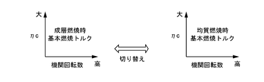
- Explanatory drawing which showed typically a mode that the calculation map used when calculating basic combustion torque according to a combustion form was switched.
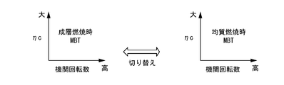
- Explanatory drawing which showed typically a mode that the calculation map used when computing the optimal ignition timing was switched according to a combustion form.
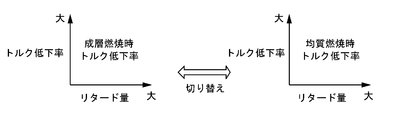
- Explanatory drawing which showed typically a mode that the calculation map used when calculating a torque decreasing rate according to a combustion form was switched.
- the flowchart which shows the flow of control of the internal combustion engine which concerns on this invention.
- FIG. 1 is an explanatory view schematically showing a schematic configuration of an internal combustion engine 1 to which a torque estimation device and a torque estimation method according to the present invention can be applied.
- the internal combustion engine 1 is mounted on a vehicle such as a car as a drive source, and has an intake passage 2 and an exhaust passage 3.
- the intake passage 2 is connected to the combustion chamber 5 via an intake valve 4.
- the exhaust passage 3 is connected to the combustion chamber 5 via an exhaust valve 6.
- the internal combustion engine 1 has a first fuel injection valve 7 for directly injecting fuel into the combustion chamber 5 and a second fuel injection valve 8 for injecting fuel into the intake passage 2 on the upstream side of the intake valve 4 There is.
- the fuel injected from the first fuel injection valve 7 and the second fuel injection valve 8 is ignited by the spark plug 9 in the combustion chamber 5.
- an air cleaner 10 for collecting foreign matters in intake, an air flow meter 11 for detecting an intake air amount, and an electric throttle valve 13 whose opening degree is controlled by a control signal from a control unit 12; Is provided.
- the air flow meter 11 is disposed upstream of the throttle valve 13.
- the air flow meter 11 incorporates a temperature sensor, and can detect the intake temperature of the intake port.
- the air cleaner 10 is disposed upstream of the air flow meter 11.
- the exhaust passage 3 is provided with an upstream exhaust catalyst device 14 such as a three-way catalyst and a downstream exhaust catalyst device 15 such as a NOx trap catalyst.
- the downstream side exhaust catalyst device 15 as a catalyst is disposed downstream of the upstream side exhaust catalyst device 14 as a catalyst.
- the internal combustion engine 1 has a turbocharger 18 coaxially provided with a compressor 16 provided in the intake passage 2 and an exhaust turbine 17 provided in the exhaust passage 3.
- the compressor 16 is disposed upstream of the throttle valve 13 and downstream of the air flow meter 11.
- the exhaust turbine 17 is disposed upstream of the upstream exhaust catalyst device 14.
- a recirculation passage 19 is connected to the intake passage 2.
- One end of the recirculation passage 19 is connected to the intake passage 2 on the upstream side of the compressor 16 and the other end is connected to the intake passage 2 on the downstream side of the compressor 16.
- An electric recirculation valve 20 capable of releasing the supercharging pressure from the downstream side of the compressor 16 to the upstream side of the compressor 16 is disposed in the recirculation passage 19.
- the recirculation valve 20 it is also possible to use a so-called check valve which opens only when the pressure on the downstream side of the compressor 16 reaches a predetermined pressure or more.
- an intercooler 21 is provided downstream of the compressor 16 to cool the intake air compressed (pressed) by the compressor 16 to improve the charging efficiency.
- the intercooler 21 is located downstream of the downstream end of the recirculation passage 19 and upstream of the throttle valve 13.
- the exhaust passage 3 is connected to an exhaust bypass passage 22 which bypasses the exhaust turbine 17 and connects the upstream side and the downstream side of the exhaust turbine 17.
- the downstream end of the exhaust bypass passage 22 is connected to the exhaust passage 3 at a position upstream of the upstream exhaust catalyst device 14.
- a motorized waste gate valve 23 for controlling the exhaust flow rate in the exhaust bypass passage 22 is disposed in the exhaust bypass passage 22.
- the waste gate valve 23 can bypass part of the exhaust gas led to the exhaust turbine 17 to the downstream side of the exhaust turbine 17, and can control the charging pressure of the internal combustion engine 1.
- the internal combustion engine 1 can carry out exhaust gas recirculation (EGR) for introducing (recirculating) a part of the exhaust gas from the exhaust gas passage 3 into the intake gas passage 2 as EGR gas.
- EGR exhaust gas recirculation
- An EGR passage 24 connected to the passage 2 is provided. One end of the EGR passage 24 is connected to the exhaust passage 3 at a position between the upstream side exhaust catalyst device 14 and the downstream side exhaust catalyst device 15, and the other end is on the downstream side of the air flow meter 11 and on the upstream side of the compressor 16. Is connected to the intake passage 2 at the following position.
- the EGR passage 24 is provided with an electrically operated EGR valve 25 for controlling the flow rate of the EGR gas in the EGR passage 24 and an EGR cooler 26 capable of cooling the EGR gas.
- Reference numeral 27 in FIG. 1 denotes a collector portion of the intake passage 2.
- the internal combustion engine 1 has a variable compression ratio mechanism 34 capable of changing the mechanical compression ratio of the internal combustion engine 1 by changing the top dead center position of the piston 33 reciprocating in the cylinder bore 32 of the cylinder block 31. ing. That is, the internal combustion engine 1 can change the mechanical compression ratio by changing the sliding range of the piston 33 with respect to the inner circumferential surface 32 a of the cylinder bore 32. In other words, the internal combustion engine 1 can change the mechanical compression ratio by changing the sliding range of the piston 33 with respect to the cylinder.
- the mechanical compression ratio is a compression ratio determined by the top dead center position and the bottom dead center position of the piston 33.
- the piston 33 has a first piston ring 35 on the piston crown surface side, and a second piston ring 36 that is farther from the piston crown surface than the first piston ring.
- the first piston ring 35 and the second piston ring 36 are so-called compression rings, which eliminate the gap between the piston 33 and the inner circumferential surface 32 a of the cylinder bore 32 and are used for air tightness.
- the variable compression ratio mechanism 34 utilizes a double link type piston-crank mechanism in which a piston 33 and a crank pin 38 of a crankshaft 37 are linked by a plurality of links.
- the variable compression ratio mechanism 34 includes a lower link 39 rotatably mounted on the crank pin 38, an upper link 40 connecting the lower link 39 and the piston 33, and a control shaft 41 provided with an eccentric shaft 41a.
- a control link 42 connecting the eccentric shaft 41 a and the lower link 39 is provided.
- the crankshaft 37 is provided with a plurality of journals 43 and crank pins 38.
- the journal portion 43 is rotatably supported between the cylinder block 31 and the crank bearing bracket 44.
- the upper link 40 is rotatably attached to the piston pin 45 at one end, and is rotatably connected to the lower link 39 by the first connection pin 46 at the other end.
- One end of the control link 42 is rotatably connected to the lower link 39 by the second connection pin 47, and the other end is rotatably attached to the eccentric shaft portion 41 a of the control shaft 41.
- the first connection pin 46 and the second connection pin 47 are press-fitted and fixed to the lower link 39.
- the control shaft 41 is disposed parallel to the crankshaft 37 and rotatably supported by the cylinder block 31. More specifically, the control shaft 41 is rotatably supported between the crank bearing bracket 44 and the control shaft bearing bracket 48.
- An oil pan upper 49 a is attached to the lower portion of the cylinder block 31. Further, an oil pan lower 49b is attached to the lower part of the oil pan upper 49a.
- the rotation of the drive shaft 53 is transmitted to the control shaft 41 via the first arm 50, the second arm 51, and the intermediate arm 52.
- the intermediate arm 52 connects the first arm 50 and the second arm 51.
- the drive shaft 53 is located outside the oil pan upper 49 a and disposed in parallel with the control shaft 41.
- the first arm 50 is fixed to the drive shaft 53.
- An intermediate arm 52 is rotatably connected to the first arm 50 via a pin member 54a.
- the intermediate arm 52 is rotatably connected to the second arm 51 whose other end is fixed to the control shaft 41 via the pin member 54 b.
- the drive shaft 53, the first arm 50 and one end of the intermediate arm 52 are accommodated in a housing 55 mounted on the side surface of the oil pan upper 49a.
- the drive shaft 53 is connected at one end to an electric motor 56 as an actuator via a reduction gear (not shown). That is, the drive shaft 53 can be rotationally driven by the electric motor 56.
- the rotational speed of the drive shaft 53 is obtained by reducing the rotational speed of the electric motor 56 by the reduction gear.
- the rotation of the electric motor 56 is controlled by the control unit 12 as a control unit so that the mechanical compression ratio of the internal combustion engine 1 becomes a compression ratio corresponding to the operating conditions.
- the control unit 12 is a known digital computer provided with a CPU, a ROM, a RAM and an input / output interface.
- the control unit 12 includes a crank angle sensor 61 for detecting a crank angle of a crankshaft 37, an accelerator opening sensor 62 for detecting an amount of depression of an accelerator pedal, and an oil temperature of engine oil, in addition to the detection signal of the air flow meter 11 described above. Detection signals of various sensors such as an oil temperature sensor 63 that detects the temperature, a water temperature sensor 64 that detects the cooling water temperature, and a boost pressure sensor 65 that detects the boost pressure (intake pressure) in the collector unit 27 are input. . The control unit 12 calculates the required load (engine load) of the internal combustion engine using the detection value of the accelerator opening sensor 62.
- the crank angle sensor 61 can detect the engine speed of the internal combustion engine 1.
- the water temperature sensor 64 detects the temperature of the cooling water in the water jacket 31 a in the cylinder block 31.
- control unit 12 controls the fuel injection amount and fuel injection timing by the first fuel injection valve 7 and the second fuel injection valve 8, the ignition timing by the spark plug 9, the ignition timing of the throttle valve 13 based on detection signals of various sensors.
- the opening degree, the opening degree of the recirculation valve 20, the opening degree of the waste gate valve 23, the opening degree of the EGR valve 25, the mechanical compression ratio of the internal combustion engine 1 by the variable compression ratio mechanism 34, etc. are optimally controlled. .
- the control unit 12 switches between the two combustion modes in accordance with the operating state.
- the two combustion modes are stratified combustion and homogeneous combustion. That is, the internal combustion engine 1 can switch the combustion mode to stratified combustion or homogeneous combustion.
- stratified combustion fuel is injected during the compression stroke to form a rich mixture around the spark plug 9 and ignited.
- homogeneous combustion fuel is diffused during the intake stroke to diffuse the fuel to form a homogeneous mixture in the combustion chamber 5 and ignited.
- the control unit 12 also corresponds to a control unit that controls the combustion mode in the cylinder (in the combustion chamber 5).
- control unit 12 controls the combustion mode of the internal combustion engine 1 if the operating state of the internal combustion engine 1 is an idle operating state. Control to achieve stratified combustion. Further, for example, when the upstream exhaust catalyst device 14 and the downstream exhaust catalyst device 15 do not need to be warmed up, the control unit 12 controls the combustion form of the internal combustion engine 1 to be homogeneous combustion.
- the control unit 12 needs to warm up the upstream side exhaust catalyst device 14 and the downstream side exhaust catalyst device 15. It is determined that there is. That is, the control unit 12 corresponds to a determination unit that can determine whether the catalyst temperature of the upstream side exhaust catalyst device 14 and the downstream side exhaust catalyst device 15 is in a warmed-up state.
- the engine torque can not be estimated accurately without considering the combustion mode.
- FIG. 2 is a block diagram showing the process of calculating the engine torque implemented in the control unit 12.
- the basic combustion torque calculation unit 71 calculates the basic combustion torque using the charging efficiency and the engine speed.
- the charging efficiency is calculated, for example, using an intake pressure (supercharging pressure), an accelerator opening degree, an intake temperature, and an engine speed.
- the basic combustion torque calculation unit 71 switches (differentiates) a calculation map used when calculating the basic combustion torque according to the combustion mode of the internal combustion engine 1. That is, in the control unit 12, a stratification combustion torque calculation map used during stratified combustion and a homogeneous combustion torque calculation map used during homogeneous combustion are prepared (stored) in advance. Therefore, the basic combustion torque calculation unit 71 can calculate the basic combustion torque reflecting the difference between the thermal efficiency of stratified combustion and the thermal efficiency of homogeneous combustion.
- the basic combustion torque is calculated from the charging efficiency and the engine speed according to the stratification combustion torque calculation map and the homogeneous combustion torque calculation map.
- the MBT calculation unit 72 calculates MBT (Minimum advance for the best torque), which is the optimal ignition timing, using the charging efficiency and the engine speed.
- the MBT is an ignition timing at which the output and the fuel consumption rate become the best.
- the MBT calculation unit 72 switches (differentiates) the calculation map used when calculating the optimal ignition timing according to the combustion mode of the internal combustion engine 1. That is, in the control unit 12, the MBT calculation map for stratified combustion used at the time of stratified combustion and the MBT calculation map for homogeneous combustion used at the time of homogeneous combustion are prepared (stored) in advance. Therefore, the MBT calculation unit 72 can calculate the optimal ignition timing that reflects the difference between the thermal efficiency of stratified combustion and the thermal efficiency of homogeneous combustion.
- the MBT calculation map for stratified combustion and the MBT calculation map for homogeneous combustion calculate the optimal ignition timing (MBT) from the charging efficiency and the engine speed.
- the ignition timing correction amount calculation unit 73 calculates a torque reduction rate with respect to the retardation amount of the ignition timing from the optimum ignition timing calculated by the MBT calculation unit 72.
- the ignition timing correction amount calculation unit 73 switches (uses) a calculation map used when calculating the torque reduction rate as the ignition timing correction amount according to the combustion mode of the internal combustion engine 1. That is, in the control unit 12, a correction amount calculation map for stratified combustion at the time of stratified combustion and a correction amount calculation map for homogeneous combustion at the time of homogeneous combustion are prepared (stored) in advance. Therefore, in the ignition timing correction amount calculation unit 73, the torque reduction rate with respect to the retardation amount of the ignition timing from the optimum ignition timing in stratified combustion, the torque reduction rate with respect to the retardation amount of the ignition timing from the optimum ignition timing with homogeneous combustion, It is possible to calculate the torque reduction rate that reflects the difference between
- the stratification combustion correction amount calculation map and the homogeneous combustion correction amount calculation map calculate the torque reduction rate according to the retardation amount of the ignition timing from the optimum ignition timing.
- the ignition timing of the internal combustion engine 1 is retarded from the optimal ignition timing, for example, when catalyst warmup of the upstream side exhaust catalyst device 14 and the downstream side exhaust catalyst device 15 is necessary or when knocking is detected.
- the combustion torque correction unit 74 corrects the basic combustion torque calculated by the basic combustion torque calculation unit using the torque decrease rate to calculate the combustion torque.
- the combustion torque is calculated by taking into consideration the torque correction by fuel cut (fuel cut) and the torque correction according to the air fuel ratio.
- the fuel cut torque correction unit 75 calculates the torque correction amount by the fuel cut (fuel cut).
- the torque correction amount corresponding to the air-fuel ratio is calculated by the A / F torque correction unit 76.
- the friction torque correction unit 77 mechanical friction torque caused by mechanical friction of the internal combustion engine 1, pumping loss torque caused by the pumping loss of the internal combustion engine 1, and combustion torque calculated by the combustion torque correction unit 74
- the engine torque is calculated by performing a correction taking into account the accessory load torque resulting from the load of the accessory 1. That is, in the present embodiment, the combustion torque correction unit 74 and the friction torque correction unit 77 constitute an engine torque calculation unit that calculates an engine torque. Then, the engine torque of the internal combustion engine 1 is calculated using the basic combustion torque and the torque reduction rate.
- the mechanical friction torque is calculated by the engine mechanical friction torque calculation unit 78.
- the pumping loss torque is calculated by the engine pumping loss torque calculation unit 79.
- the accessory load torque is calculated by the accessory load torque calculation unit 80.
- the accessory load torque is, for example, attributable to driving of an alternator, an air conditioner (A / C) and power steering.
- An alternator load torque, an air conditioner load torque, and a power steering load torque are input to the accessory load torque calculation unit 80 of this embodiment. Then, the accessory load torque calculation unit 80 calculates accessory load torque based on these load torques.
- the alternator load torque is calculated by the alternator load torque calculation unit 81.
- the air conditioner load torque is calculated by the air conditioner load torque calculation unit 82.
- the power steering load torque is calculated by the power steering load torque calculation unit 83.
- the basic combustion torque calculation unit 71 calculates the basic combustion torque in accordance with the combustion mode of the internal combustion engine 1.
- the engine torque can be estimated more accurately than in the case where the engine torque is estimated on the assumption of either one of the stratified combustion and the homogeneous combustion different in combustion efficiency. That is, regardless of the combustion mode of the internal combustion engine 1, the basic combustion torque can be accurately calculated, and the engine torque can be generally calculated with high accuracy.
- the MBT calculation unit 72 calculates the optimal ignition timing according to the combustion mode of the internal combustion engine 1.
- the ignition timing correction amount can be accurately calculated, and the engine torque can be generally calculated with high accuracy.
- the ignition timing correction amount calculation unit 73 calculates the torque decrease rate as the ignition timing correction amount in accordance with the combustion mode of the internal combustion engine 1.
- FIG. 6 is a flowchart showing the flow of control in the present embodiment.
- step S1 it is determined whether the combustion form of the internal combustion engine 1 is stratified combustion. In step S1, the process proceeds to step S2 in the case of stratified combustion, and proceeds to step S3 in the case of not being stratified combustion (in the case of homogeneous combustion).
- step S2 engine torque is estimated by calculating estimated torque for stratified combustion. That is, the basic combustion torque calculation unit 71, the MBT calculation unit 72, and the ignition timing correction amount calculation unit 73 calculate the basic combustion torque, the optimal ignition timing, and the torque decrease rate using the map for stratified combustion.
- step S3 the engine torque is estimated by calculating the estimated torque for homogeneous combustion. That is, the basic combustion torque calculation unit 71, the MBT calculation unit 72, and the ignition timing correction amount calculation unit 73 calculate the basic combustion torque, the optimal ignition timing, and the torque reduction rate using the homogeneous combustion map.
- the basic combustion torque calculation unit 71, the MBT calculation unit 72, and the ignition timing correction amount calculation unit 73 switch the maps according to the combustion mode.
- the map may be switched according to the combustion mode by at least one of the timing correction amount calculation unit 73.
- the engine torque can be estimated with high accuracy regardless of the type of combustion, as compared to the case where the engine torque is estimated on the assumption of either one of the stratified combustion and the homogeneous combustion different in combustion efficiency.
- the embodiment described above relates to a torque estimation method for an internal combustion engine and a torque estimation device for an internal combustion engine.
Landscapes
- Engineering & Computer Science (AREA)
- Chemical & Material Sciences (AREA)
- Combustion & Propulsion (AREA)
- Mechanical Engineering (AREA)
- General Engineering & Computer Science (AREA)
- Combined Controls Of Internal Combustion Engines (AREA)
Abstract
Dans la présente invention, un couple moteur d'un moteur à combustion interne est calculé à l'aide d'un couple de combustion fondamental et d'une quantité de réglage de synchronisation d'allumage. Si la forme de combustion du moteur à combustion interne est stratifiée, le couple moteur est estimé par une opération arithmétique de couple estimée pour une combustion stratifiée (étape S2). C'est-à-dire, une unité de calcul de couple de combustion fondamental, une unité de calcul MBT et une unité de calcul de réglage de synchronisation d'allumage calculent le couple de combustion fondamental, une synchronisation d'allumage optimale et un rapport de réduction de couple à l'aide d'une carte pour une combustion stratifiée. Si la forme de combustion du moteur à combustion interne est homogène, le couple moteur est estimé à l'aide d'une opération arithmétique de couple estimée pour une combustion homogène (étape S3). C'est-à-dire, l'unité de calcul de couple de combustion fondamental, l'unité de calcul MBT et l'unité de calcul de réglage de synchronisation d'allumage calculent le couple de combustion fondamental, la synchronisation d'allumage optimale et le rapport de réduction de couple à l'aide de la carte pour une combustion homogène.
Priority Applications (1)
| Application Number | Priority Date | Filing Date | Title |
|---|---|---|---|
| PCT/JP2017/031542 WO2019043902A1 (fr) | 2017-09-01 | 2017-09-01 | Procédé d'estimation de couple pour moteur à combustion interne et dispositif d'estimation de couple pour moteur à combustion interne |
Applications Claiming Priority (1)
| Application Number | Priority Date | Filing Date | Title |
|---|---|---|---|
| PCT/JP2017/031542 WO2019043902A1 (fr) | 2017-09-01 | 2017-09-01 | Procédé d'estimation de couple pour moteur à combustion interne et dispositif d'estimation de couple pour moteur à combustion interne |
Publications (1)
| Publication Number | Publication Date |
|---|---|
| WO2019043902A1 true WO2019043902A1 (fr) | 2019-03-07 |
Family
ID=65525095
Family Applications (1)
| Application Number | Title | Priority Date | Filing Date |
|---|---|---|---|
| PCT/JP2017/031542 Ceased WO2019043902A1 (fr) | 2017-09-01 | 2017-09-01 | Procédé d'estimation de couple pour moteur à combustion interne et dispositif d'estimation de couple pour moteur à combustion interne |
Country Status (1)
| Country | Link |
|---|---|
| WO (1) | WO2019043902A1 (fr) |
Citations (5)
| Publication number | Priority date | Publication date | Assignee | Title |
|---|---|---|---|---|
| JP2005120942A (ja) * | 2003-10-17 | 2005-05-12 | Nissan Motor Co Ltd | 直噴火花点火式内燃機関の制御装置 |
| JP2006063903A (ja) * | 2004-08-27 | 2006-03-09 | Toyota Motor Corp | 内燃機関 |
| JP2009133276A (ja) * | 2007-11-30 | 2009-06-18 | Mitsubishi Electric Corp | 内燃機関の制御装置 |
| JP2010127128A (ja) * | 2008-11-26 | 2010-06-10 | Nissan Motor Co Ltd | 車両の制御装置 |
| JP2012163039A (ja) * | 2011-02-07 | 2012-08-30 | Nissan Motor Co Ltd | 内燃機関の制御装置 |
-
2017
- 2017-09-01 WO PCT/JP2017/031542 patent/WO2019043902A1/fr not_active Ceased
Patent Citations (5)
| Publication number | Priority date | Publication date | Assignee | Title |
|---|---|---|---|---|
| JP2005120942A (ja) * | 2003-10-17 | 2005-05-12 | Nissan Motor Co Ltd | 直噴火花点火式内燃機関の制御装置 |
| JP2006063903A (ja) * | 2004-08-27 | 2006-03-09 | Toyota Motor Corp | 内燃機関 |
| JP2009133276A (ja) * | 2007-11-30 | 2009-06-18 | Mitsubishi Electric Corp | 内燃機関の制御装置 |
| JP2010127128A (ja) * | 2008-11-26 | 2010-06-10 | Nissan Motor Co Ltd | 車両の制御装置 |
| JP2012163039A (ja) * | 2011-02-07 | 2012-08-30 | Nissan Motor Co Ltd | 内燃機関の制御装置 |
Similar Documents
| Publication | Publication Date | Title |
|---|---|---|
| JP4159918B2 (ja) | 圧縮着火式内燃機関の燃料カット制御装置 | |
| CN104321517B (zh) | 内燃机的控制装置以及控制方法 | |
| CN103857893A (zh) | 内燃机的控制装置及控制方法 | |
| US9822711B2 (en) | Control device for internal combustion engine | |
| CN104302895B (zh) | 可变压缩比内燃机的控制装置 | |
| JPWO2014119354A1 (ja) | 内燃機関の制御装置および制御方法 | |
| RU2618146C1 (ru) | Устройство управления двигателем внутреннего сгорания и способ управления | |
| JP5900701B2 (ja) | 内燃機関の制御装置および制御方法 | |
| CN110730861B (zh) | 内燃机的控制方法及控制装置 | |
| JP6835235B2 (ja) | 内燃機関の制御方法及び内燃機関の制御装置 | |
| JP2005016381A (ja) | 可変圧縮比機構付き内燃機関の始動制御装置 | |
| JP2009215989A (ja) | 内燃機関の制御装置及び制御方法 | |
| JP4277623B2 (ja) | 可変圧縮比機構付き内燃機関の点火時期制御装置 | |
| WO2019043902A1 (fr) | Procédé d'estimation de couple pour moteur à combustion interne et dispositif d'estimation de couple pour moteur à combustion interne | |
| JP2004156464A (ja) | 内燃機関の圧縮比制御装置 | |
| JP2005030222A (ja) | 可変圧縮比機構付き内燃機関の点火制御装置 | |
| JP2005030253A (ja) | 可変圧縮比機構付き内燃機関の制御装置 | |
| JP6371040B2 (ja) | 内燃機関の制御装置および制御方法 | |
| JP6146095B2 (ja) | 内燃機関の制御装置および制御方法 | |
| JP2018123771A (ja) | 内燃機関の制御装置 | |
| JP6721119B2 (ja) | 内燃機関の制御方法及び内燃機関の制御装置 | |
| US11067023B2 (en) | Internal combustion engine diagnostic method and internal combustion engine diagnostic device | |
| JP2004353613A (ja) | 内燃機関の燃料噴射制御装置 | |
| JP2014224462A (ja) | 内燃機関の制御装置および制御方法 |
Legal Events
| Date | Code | Title | Description |
|---|---|---|---|
| 121 | Ep: the epo has been informed by wipo that ep was designated in this application |
Ref document number: 17923785 Country of ref document: EP Kind code of ref document: A1 |
|
| NENP | Non-entry into the national phase |
Ref country code: DE |
|
| 122 | Ep: pct application non-entry in european phase |
Ref document number: 17923785 Country of ref document: EP Kind code of ref document: A1 |
|
| NENP | Non-entry into the national phase |
Ref country code: JP |