WO2019044033A1 - Dispositif d'alimentation en produits chimiques et système de purification d'eau associé à ce dispositif - Google Patents
Dispositif d'alimentation en produits chimiques et système de purification d'eau associé à ce dispositif Download PDFInfo
- Publication number
- WO2019044033A1 WO2019044033A1 PCT/JP2018/016708 JP2018016708W WO2019044033A1 WO 2019044033 A1 WO2019044033 A1 WO 2019044033A1 JP 2018016708 W JP2018016708 W JP 2018016708W WO 2019044033 A1 WO2019044033 A1 WO 2019044033A1
- Authority
- WO
- WIPO (PCT)
- Prior art keywords
- water
- supply device
- treated
- drug
- membrane
- Prior art date
- Legal status (The legal status is an assumption and is not a legal conclusion. Google has not performed a legal analysis and makes no representation as to the accuracy of the status listed.)
- Ceased
Links
Images







Classifications
-
- B—PERFORMING OPERATIONS; TRANSPORTING
- B01—PHYSICAL OR CHEMICAL PROCESSES OR APPARATUS IN GENERAL
- B01D—SEPARATION
- B01D21/00—Separation of suspended solid particles from liquids by sedimentation
-
- B—PERFORMING OPERATIONS; TRANSPORTING
- B01—PHYSICAL OR CHEMICAL PROCESSES OR APPARATUS IN GENERAL
- B01D—SEPARATION
- B01D21/00—Separation of suspended solid particles from liquids by sedimentation
- B01D21/01—Separation of suspended solid particles from liquids by sedimentation using flocculating agents
-
- B—PERFORMING OPERATIONS; TRANSPORTING
- B01—PHYSICAL OR CHEMICAL PROCESSES OR APPARATUS IN GENERAL
- B01J—CHEMICAL OR PHYSICAL PROCESSES, e.g. CATALYSIS OR COLLOID CHEMISTRY; THEIR RELEVANT APPARATUS
- B01J4/00—Feed or outlet devices; Feed or outlet control devices
-
- C—CHEMISTRY; METALLURGY
- C02—TREATMENT OF WATER, WASTE WATER, SEWAGE, OR SLUDGE
- C02F—TREATMENT OF WATER, WASTE WATER, SEWAGE, OR SLUDGE
- C02F1/00—Treatment of water, waste water, or sewage
-
- C—CHEMISTRY; METALLURGY
- C02—TREATMENT OF WATER, WASTE WATER, SEWAGE, OR SLUDGE
- C02F—TREATMENT OF WATER, WASTE WATER, SEWAGE, OR SLUDGE
- C02F1/00—Treatment of water, waste water, or sewage
- C02F1/52—Treatment of water, waste water, or sewage by flocculation or precipitation of suspended impurities
-
- C—CHEMISTRY; METALLURGY
- C02—TREATMENT OF WATER, WASTE WATER, SEWAGE, OR SLUDGE
- C02F—TREATMENT OF WATER, WASTE WATER, SEWAGE, OR SLUDGE
- C02F1/00—Treatment of water, waste water, or sewage
- C02F1/72—Treatment of water, waste water, or sewage by oxidation
- C02F1/76—Treatment of water, waste water, or sewage by oxidation with halogens or compounds of halogens
-
- C—CHEMISTRY; METALLURGY
- C02—TREATMENT OF WATER, WASTE WATER, SEWAGE, OR SLUDGE
- C02F—TREATMENT OF WATER, WASTE WATER, SEWAGE, OR SLUDGE
- C02F1/00—Treatment of water, waste water, or sewage
- C02F1/72—Treatment of water, waste water, or sewage by oxidation
- C02F1/78—Treatment of water, waste water, or sewage by oxidation with ozone
Definitions
- the present invention relates to a drug supply device and a water purification system.
- the present invention relates to a drug supply device capable of supplying a fixed amount of drug to treated water without using an expensive device such as a metering pump, and a water purification system using the same.
- treated water is taken from water sources such as rivers and reservoirs in water treatment plants, and suspended matter and colloids are removed from treated water through unit processes of aggregation, flocculation, sedimentation, filtration and disinfection (for example, refer to Patent Document 1).
- Patent Document 1 proposes a flocculant injection device including a flocculant storage tank, a flocculant transfer metering pump, a water supply device using treated water after purification processing as a water supply source, an injector, and a nozzle mounting injection pipe.
- the present invention has been made in view of the problems of the prior art. And the objective of this invention is providing the chemical
- a drug supply device includes a drug-permeable membrane and a membrane supporting portion for supporting the membrane, and a drug storage portion for containing a drug
- a water supply unit for supplying water to be treated to the membrane, a mixing unit for mixing the water to be treated supplied from the water supply unit, and the drug having permeated through the film; and discharging the water to be treated mixed with the drug.
- a discharge unit for supplying water to be treated to the membrane, a mixing unit for mixing the water to be treated supplied from the water supply unit, and the drug having permeated through the film; and discharging the water to be treated mixed with the drug.
- a discharge unit for supplying water to be treated to the membrane, a mixing unit for mixing the water to be treated supplied from the water supply unit, and the drug having permeated through the film; and discharging the water to be treated mixed with the drug.
- the water purification system according to the second aspect of the present invention is disposed in parallel with the medicine supply device, the first bypass pipe provided with the medicine supply device, and the first bypass pipe, and A main pipe connecting a pump disposed on the upstream side and a filtration device disposed on the downstream side with respect to the medicine supply device is provided.
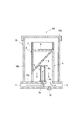
- FIG. 1 is a cross-sectional view showing an example of the medicine supply device according to the first embodiment.
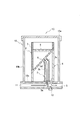
- FIG. 2 is a cross-sectional view showing an example of the medicine supply device according to the second embodiment.
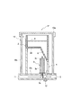
- FIG. 3 is a cross-sectional view showing an example of the medicine supply device according to the third embodiment.
- FIG. 4 is a cross-sectional view showing an example of the medicine supply device according to the fourth embodiment.
- FIG. 5 is a cross-sectional view showing an example of the medicine supply device according to the fifth embodiment.
- FIG. 6 is a cross-sectional view showing an example of the medicine supply device according to the sixth embodiment.
- FIG. 7 is a schematic view showing an example of the water purification system according to the first embodiment.
- FIG. 1 is a cross-sectional view showing an example of the medicine supply device according to the first embodiment.
- FIG. 2 is a cross-sectional view showing an example of the medicine supply device according to the second embodiment.
- FIG. 3 is a cross-sectional view showing an
- FIG. 8 is a schematic view showing an example of the water purification system according to the second embodiment.
- FIG. 9 is a schematic view showing an example of the water purification system according to the third embodiment.
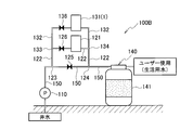
- FIG. 10 is a schematic view showing an example of the water purification system according to the fourth embodiment.
- FIG. 11 is a schematic view showing an example of the water purification system according to the fifth embodiment.
- FIG. 12 is a cross-sectional view of the drug supply device used in Example 1.
- FIG. 13 is a schematic view showing the configuration of the water purification system used in Example 1.
- FIG. 14 is a schematic view showing the configuration of the water purification system used in Comparative Example 1.
- FIG. 15 is a schematic view showing the configuration of the water purification system used in Comparative Example 2.
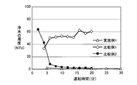
- FIG. 16 is a graph showing the relationship between operating time and turbidity for water purified by the water purification system of the example and the comparative example.
- treated water water or rainwater pumped out of a water source such as a well, a river, or a pond whose water quality is improved by the water purification system.
- clean water treated water whose water quality has been improved and purified.
- the medicine supply device 1 according to the present embodiment will be described using the medicine supply device 1A to the medicine supply device 1F according to the first to sixth embodiments, but the present embodiment is limited to these embodiments. Absent.
- the medicine supply device 1A includes a medicine storage unit 2, a water supply unit 3, a mixing unit 4, and a discharge unit 5.
- the medicine supply device 1A of the present embodiment is provided with the outer storage portion 10.
- the medicine container 2, the water supply unit 3, and the mixing unit 4 are accommodated in the outer container 10.
- the outer accommodation portion 10 includes a lid portion 10a, a side portion 10b, and a bottom portion 10c.
- the shape of the side portion 10b is not particularly limited, but in the present embodiment, the side portion 10b is formed in a substantially cylindrical shape, the bottom portion 10c is provided to cover one open portion, and the other open portion is removable by the lid 10a. It is provided like.
- transducing part 11 which introduce
- emitted are provided in the outer side of the outer side accommodating part 10 with respect to the bottom part 10c.
- the medicine container 2 includes a membrane 6 and a membrane support 7. Then, the drug storage unit 2 stores the drug 8. In the embodiment of FIG. 1, the drug 8 is contained in the space formed by the membrane 6 and the membrane support 7.
- the membrane support 7 supports the membrane 6.
- the membrane support 7 is formed in a cylindrical shape, and the side walls of the membrane support 7 have substantially the same length at any position on the circumference.
- the open portion at one end of the membrane support 7 is entirely covered by the membrane 6.
- the membrane 6 is permeable to the drug 8.
- the drug 8 penetrates the membrane 6, the drug 8 is retained inside the membrane 6. Therefore, when the water to be treated is supplied to the membrane 6, the medicine 8 and the water to be treated are brought into contact and mixed.
- the membrane 6 is not particularly limited as long as the drug 8 can penetrate, but it is preferable that the membrane 6 has pores and the pore size of the membrane is larger than the molecular size of the active ingredient contained in the drug 8. By setting the pore size of the membrane to such a size, an appropriate amount of the active ingredient contained in the drug 8 can be retained in the membrane 6.
- the membrane 6 has pores, and the pore diameter of the pores is more preferably 0.01 ⁇ m to 10 ⁇ m.
- the concentration of the drug 8 in the water to be treated can be quickly made appropriate.
- the pore diameter of the membrane 6 is set to 10 ⁇ m or less, the supply of the excess drug 8 can be suppressed.
- the material for forming the membrane 6 is not particularly limited, but at least one selected from the group consisting of cellulose acetate, polyacrylonitrile, polysulfone, polyethersulfone, polyethylene, polypropylene, polyvinylidene fluoride and ceramics such as alumina. preferable. Among these, from the viewpoint of ease of washing, flexibility, handling and the like, the material forming the film 6 is preferably cellulose acetate. Specific examples of the membrane 6 include, for example, MF membrane (Microfiltration Membrane), UF membrane (Ultrafiltration Membrane) and the like.
- the thickness of the film 6 is not particularly limited, but is preferably 1 ⁇ m to 100 ⁇ m. By setting the thickness of the film 6 to 1 ⁇ m or more, breakage of the film can be suppressed. Moreover, supply of the chemical
- the medicine container 2 is preferably removable from the medicine supply device 1A.
- the medicine 8 can be replenished to the medicine container 2 outside the medicine supply device 1A. Further, by making the medicine container 2 removable from the medicine supply device 1A, the medicine container 2 for replacement in which the medicine 8 is replenished, and the medicine container 2 in which the medicine 8 is used and the remaining amount is reduced. And can easily be replaced.
- medical agent 8 will not be specifically limited if it contains the active ingredient which contributes to processing a to-be-processed water.
- the drug 8 include an oxidizing agent, a coagulant and the like.
- the oxidizing agent oxidizes metal ions in the water to be treated. Specifically, it has an effect of oxidizing divalent iron ions contained in the water to be treated to trivalent iron ions.
- the divalent iron ion is oxidized by oxygen in the air, gradually changes to a form such as Fe (OH) 3 or Fe 2 O 3 which is hardly soluble in water, and may be precipitated in household water. Therefore, by adding an oxidizing agent to the water to be treated, divalent iron ions dissolved in water can be forcibly oxidized to trivalent iron ions, and colloids hardly soluble in water can be formed.
- the metal ion oxidized with an oxidizing agent is not limited to iron.
- the oxidizing agent preferably contains ozone or chlorine because it can be easily added to the water to be treated and efficiently oxidizes metal ions.
- chlorine-based agents are preferable as the oxidizing agent.
- the chlorine agent at least one selected from the group consisting of sodium hypochlorite, calcium hypochlorite and chlorinated isocyanuric acid can be used.
- calcium hypochlorite at least one of exfoliated powder (available chlorine 30%) and highly exfoliated powder (available chlorine 70%) can be used.
- chlorinated isocyanuric acid at least one selected from the group consisting of sodium trichloroisocyanurate, potassium trichloroisocyanurate, sodium dichloroisocyanurate and potassium dichloroisocyanurate can be used.
- sodium hypochlorite is a liquid, and can be quantitatively added to the water to be treated using an injection method by a metering pump, so it can be particularly preferably used.
- the inorganic highly exfoliated powder has very high solubility in water to be treated, it can exhibit a high oxidizing effect.
- the flocculating agent can flocculate colloids and the like formed by the oxidizing agent to form flocs.
- the formed floc can be easily removed by a filtration device or the like.
- flocculant For example, an aluminum-type coagulant
- the aluminum-based coagulant include aluminum chloride and aluminum sulfate.
- iron-based coagulant examples include ferrous sulfate (FeSO 4 ), ferric sulfate (Fe 2 (SO 4 ) 3 ), ferric chloride (FeCl 3 ), polyferric sulfate ([Fe 2 (OH) n (SO 4 ) 3-n / 2 ] m ), polysilica-iron flocculant ([SiO 2 ] n ⁇ [Fe 2 O 3 ]), and the like.
- ferrous sulfate FeSO 4
- ferric sulfate Fe 2 (SO 4 ) 3
- ferric chloride FeCl 3
- polyferric sulfate [Fe 2 (OH) n (SO 4 ) 3-n / 2 ] m
- polysilica-iron flocculant [SiO 2 ] n ⁇ [Fe 2 O 3 ]
- the state of the drug 8 is not particularly limited, and may be a solid drug or a liquid drug.
- the shape of the solid drug is not particularly limited.
- the solid drug includes, for example, shapes such as tablets and granules.
- the water to be treated supplied from the water supply unit 3 penetrates the membrane 6 to dissolve the solid drug in contact with the membrane 6.
- the solid drug dissolved in the water to be treated is retained in the membrane 6 as a liquid drug containing the active ingredient.
- the to-be-processed water supplied from the water supply part 3 contacts with the film
- the water supply unit 3 supplies the water to be treated to the membrane 6.
- the water supply unit 3 is disposed on the opposite side of the membrane 6 to the drug 8.
- the water supply unit 3 is disposed such that the water to be treated is supplied to the substantially central portion in the radial direction of the medicine storage unit 2 so that the amount of the water to be treated in contact with the membrane 6 is increased.
- the water supply unit 3 is connected to the bottom 10 c at a substantially central portion in the radial direction of the mixing unit 4.
- the water supply unit 3 is not particularly limited as long as it can supply the water to be treated to the membrane 6, but for example, a nozzle can be used.
- the water supply unit 3 includes a supply port 3a, a side portion 3b, and a discharge port 3c.
- the side portion 3 b is formed such that the introduction portion 11 and the water supply portion 3 communicate with each other through the supply port 3 a. Then, the water to be treated introduced from the introduction unit 11 is discharged from the outlet 3 c through the supply port 3 a, and the water to be treated is supplied to the membrane 6.
- the water supply unit 3 is linear, but the shape of the water supply unit 3 is not particularly limited.
- the film 6 and the water supply unit 3 are disposed with a gap in the thickness direction of the film 6.
- the water supply unit 3 is disposed such that the thickness direction of the membrane 6 is substantially parallel to the supply direction of the water to be treated supplied from the water supply unit 3.
- the supply direction of the to-be-processed water here means the discharge
- substantially parallel may mean that the thickness direction of the membrane 6 may be inclined by about ⁇ 15 degrees with respect to the supply direction of the water to be treated supplied from the water supply unit 3.
- the amount of water to be treated supplied from the water supply unit 3 is preferably such that the water to be treated can contact the membrane 6.
- the mixing unit 4 can mix the water to be treated and the medicine 8.
- the flow rate of the water to be treated is a linear velocity of 8 cm / s to 10 cm / s, and the gap between the tip on the membrane 6 side of the water supply unit 3 and the membrane is 5 mm to 10 mm.
- a pedestal 9 smaller than the size of the membrane 6 in the planar direction of the membrane 6 be provided at the tip of the water supply portion 3.
- the water to be treated supplied from the water supply portion 3 passes between the pedestal portion 9 and the membrane 6, so that the water to be treated contacts the membrane 6 for a long time. Can be maintained. Therefore, the supply amount of the drug 8 to the water to be treated can be kept more constant.
- the distance between the top surface of the pedestal 9 and the lower surface of the membrane 6 is preferably 2 mm to 10 mm.
- the distance between the inner wall of the mixing unit 4 and the radial outer side of the pedestal 9 is preferably 2 mm to 10 mm.
- the pedestal 9 is provided with a hole at a substantially central portion in a sectional view, and is connected to the tip of the water supply unit 3 so as to communicate with the water supply unit 3.
- the pedestal portion 9 is formed in a circular shape in top view so as to spread outward from a hole at a substantially central portion in a sectional view.
- a projection for supporting the film 6 may be provided on the surface of the pedestal 9. By providing such a projection on the pedestal 9, the membrane 6 can be supported by the projection so that the membrane 6 does not sag.
- the mixing unit 4 mixes the water to be treated supplied from the water supply unit 3 with the medicine 8 having the membrane 6 penetrated.
- the shape of the mixing unit 4 is not particularly limited, but in the present embodiment, the mixing unit 4 is substantially cylindrical and disposed so as to sandwich the film 6 between the film support 7 and the mixing unit 4 .
- the water supply unit 3 is disposed inside the mixing unit 4. Then, the water to be treated is supplied from the water supply unit 3 to the membrane 6 holding the drug 8 in the space formed by the mixing unit 4 and the membrane 6, and the water to be treated and the drug 8 are mixed in the mixing unit 4 . Thereafter, the water to be treated mixed with the drug 8 moves from the mixing unit 4 to the discharge unit 5.
- the discharge unit 5 discharges the treated water mixed with the medicine 8.
- the water to be treated containing the drug 8 discharged from the discharge unit 5 is filtered by, for example, a filter device and used by the user as domestic water.
- the discharge unit 5 may be provided with a water drain 12 for discharging the water to be treated accumulated in the discharge unit 5.
- the medicine supply device 1B according to the second embodiment will be described with reference to FIG.
- symbol is attached
- the thickness direction of the membrane 6 is arranged to be inclined with respect to the supply direction of the water to be treated supplied from the water supply unit 3. That is, the film 6 is disposed so that the thickness direction thereof is not parallel to the supply direction of the water to be treated supplied from the water supply unit 3. Specifically, the thickness direction of the membrane 6 is arranged to be inclined with respect to the extension direction of the water supply unit 3.
- the contact area of the membrane 6 and the water to be treated can be easily changed by controlling the flow velocity of the water to be treated and the height at which the water to be treated is sprayed. Specifically, the contact area between the membrane 6 and the water to be treated can be increased by increasing the height at which the water to be treated is sprayed. Moreover, when the height to which the water to be treated is sprayed is reduced, the contact area between the membrane 6 and the water to be treated can be narrowed. Therefore, the concentration of the drug 8 in the water to be treated can be easily changed by a simple means of controlling the flow rate of the water to be treated supplied.
- the thickness direction of the film is inclined 45 degrees to 89 degrees with respect to the supply direction of the water to be treated supplied from the water supply unit 3.
- the inclination of the film 6 is preferably in the range not exceeding 89 degrees, because it is easy to adjust the contact area between the film 6 and the water to be treated if the inclination of the film 6 is large.
- the thickness direction of the membrane 6 is arranged to be inclined with respect to the supply direction of the water to be treated supplied from the water supply unit 3.
- the water supply unit 3 is disposed outside the approximate center in the radial direction of the mixing unit 4.
- the tip of the water supply unit 3 on the side of the membrane 6 is bent toward the center in the radial direction of the mixing unit 4 to form a bend 3d.
- the tip of the water supply unit 3 is bent. Therefore, the contact area between the membrane 6 and the water to be treated can be changed by a combination of the inclination of the membrane 6 and the inclination due to the bending of the water supply unit 3, and the concentration of the drug 8 in the water to be treated can be controlled more finely. it can. Moreover, by adjusting the positional relationship between the membrane 6 and the tip of the water supply part 3 in the height direction by bending the tip of the water supply part 3, the contact area between the membrane 6 and the water to be treated can be easily made. It can be changed.
- tip part of the water supply part 3 is 135 degrees or more and less than 180.
- the angle of the bending portion 3d in such a range, the height of the sprayed water of the treated water by the water supply unit 3 can be made sufficiently high, and the contact area between the membrane 6 and the treated water is widened. be able to.
- the angle of the bending part 3d is 180 degrees, it corresponds to the case where the water supply part 3 is linear.
- the tip of the water supply unit 3 is bent and the medicine storage unit 2 is rotatably provided.
- the medicine storage unit 2 rotatably with respect to the medicine supply device 1C, the membrane 6 and the water to be treated can be rotated by a simple method of rotating the medicine storage unit 2 as well as the spouting height of the water to be treated.
- the angle formed by the feed direction can be changed. Therefore, the contact area between the membrane 6 and the water to be treated can be controlled, and the concentration of the drug 8 supplied to the water to be treated can be controlled more easily and finely.
- the thickness direction of the membrane 6 is arranged to be inclined with respect to the supply direction of the water to be treated supplied from the water supply unit 3.
- a part of the medicine container 2 is accommodated inside the mixing unit 4.
- the concentration of the drug 8 in the water to be treated is controlled by the simple means of controlling the flow velocity of the water to be treated as in the second and third embodiments. It can be easily changed. Further, by providing the medicine storage unit 2 rotatably, the concentration of the medicine 8 to be supplied to the water to be treated can be controlled more easily and finely as in the third embodiment.
- the medicine supply device 1E according to the fifth embodiment is the medicine supply device 1D according to the fourth embodiment, in which the tip of the water supply unit 3 is bent as in the third embodiment. Specifically, in the medicine supply device 1E according to the fifth embodiment, the tip of the water supply unit 3 on the side of the membrane 6 is bent toward the center in the radial direction of the mixing unit 4 to form a bend 3d.
- the contact area between the membrane 6 and the water to be treated is changed by the combination of the inclination of the membrane 6 and the inclination due to the bending of the water supply unit 3 as in the third embodiment.
- the concentration of the drug 8 in the water to be treated can be controlled more finely.
- the contact area between the membrane 6 and the water to be treated can be easily changed by bending the tip of the water supply portion 3 and adjusting the positional relationship between the membrane 6 and the tip of the water supply portion 3 in the height direction. Can.
- a drug supply device 1F according to the sixth embodiment will be described with reference to FIG.
- symbol is attached
- the entire lower surface of the membrane support 7 is not covered with the membrane 6, and only a part of the lower surface of the membrane support 7 is covered with the membrane 6. Then, a part of the membrane support 7 not covered by the membrane 6 is formed such that the bottom 2 a to which the drug 8 does not penetrate is formed and the drug 8 can not permeate.
- the concentration of the drug 8 in the water to be treated can be adjusted more easily at the height of the water to be treated. it can. Further, by tilting only a part of the membrane 6, the amount of the drug 8 that can be stored in the drug storage unit 2 can be increased.
- the drug supply device includes the membrane through which the drug can permeate and the membrane supporting unit that supports the membrane, and supplies the water to be treated to the drug storage unit that stores the drug and the membrane. And a water supply unit.
- the medicine supply device includes a mixing unit that mixes the water to be treated supplied from the water supply unit with the medicine that has permeated the membrane, and a discharge unit that discharges the water to be treated mixed with the medicine.
- the water to be treated is supplied to the membrane through which the drug can permeate. Therefore, the medicine is supplied according to the flow rate of the water to be treated. Then, the water to be treated and the drug are mixed in the mixing unit. Therefore, the water to be treated and the drug are uniformly mixed at a constant concentration. Therefore, according to the medicine supply device according to the present embodiment, the medicine can be quantitatively mixed with the water to be treated with a simple configuration. Therefore, it is possible to supply a constant amount of medicine to the water to be treated without using expensive equipment such as a constant rate pump.
- Water purification system 100 The water purification system 100 according to the present embodiment will be described using the first to fifth embodiments, but the present embodiment is not limited to these embodiments.
- the water purification system 100A according to the first embodiment will be described using FIG. 7.
- the drug supply device 1 described above can be used for the water purification system 100A according to the present embodiment.
- the water purification system 100A according to the present embodiment includes the medicine supply device 1, the first bypass pipe 132, and the main pipe 150.
- one of the main pipes 150 is in a state of being immersed in the well water, and the other is connected to a water tank or the like inside the building.
- the main pipe 150 is provided with a pump 110 for pumping up the water to be treated (well water) from the well, and a filtration device 140 for filtering out turbid components contained in the water to be treated.
- the main pipe 150 connects the pump 110 and the filtration device 140. Then, the water to be treated which is pumped up by the pump 110 and passes through the main pipe 150 passes through the filter device 140 and is used by the user as domestic water.
- the pump 110 is disposed upstream of the drug supply device 1.
- the pump 110 is not particularly limited as long as it can pump the water to be treated and can supply the water to the water purification system 100A.
- As the pump 110 for example, an automatic pump incorporating a pressure switch can be used.
- an oxidizing agent and a coagulant are added to the water to be treated which has been pumped up from the well water by the pump 110 and passed through the main pipe 150, and the aggregates are filtered by the filter device 140.
- An example of filtration is shown.
- the oxidant is supplied by the oxidant supply device 121, and the coagulant is supplied from the coagulant supply device 131.
- the medicine supply device 1 may be the oxidant supply device 121, in the present embodiment, an example in which the medicine supply device 1 is the coagulant supply device 131 will be described.
- the oxidizing agent supply device 121 supplies an oxidizing agent to the water to be treated.
- the oxidant supply device 121 is provided in the second bypass pipe 122.
- the main pipe 150 is disposed in parallel with the second bypass pipe 122.
- the upstream end of the second bypass pipe 122 is connected to the main pipe 150 at the connection portion 123.
- the downstream end of the second bypass pipe 122 is connected to the main pipe 150 at the connection portion 124.
- a part of the water to be treated that is pumped up by the pump 110 and passes through the main pipe 150 passes through the second bypass pipe 122 via the connection portion 123 and is supplied to the oxidant supply device 121.
- the to-be-processed water to which the oxidizing agent was supplied by the oxidizing agent supply apparatus 121 passes the 2nd bypass piping 122, and returns to the main piping 150 via the connection part 124.
- the coagulant supply device 131 supplies the coagulant to the water to be treated to which the oxidant is supplied.
- the drug supply device is the coagulant supply device 131.
- the coagulant supply device 131 (drug supply device 1) is provided in the first bypass pipe 132.
- the main pipe 150 is disposed in parallel with the first bypass pipe 132.
- the coagulant supply device 131 supplies the coagulant to the water to be treated to which the oxidant has been supplied by the oxidant supply device 121.
- the flocculating agent is used to flocculate the colloidal metal component by the action of the oxidizing agent.
- the upstream end of the first bypass pipe 132 is connected to the main pipe 150 at the connection portion 133.
- the downstream end of the first bypass pipe 132 is connected to the main pipe 150 at the connection portion 134. Then, the oxidizing agent is supplied, and a part of the water to be treated which passes through the main pipe 150 passes through the first bypass pipe 132 via the connection portion 133 and is supplied to the coagulant supplying device 131. And the to-be-processed water to which the coagulant
- the water to be treated is supplied from the introduction unit 11 to the water supply unit 3 as described above. Then, the water to be treated is supplied from the water supply unit 3 to the membrane 6 of the drug storage unit 2 and mixed with the coagulant (drug 8) in the mixing unit 4. And the to-be-processed water with which the coagulant
- the coagulant supply device 131 is provided in the first bypass pipe 132. Therefore, for example, even if the fluctuation of the flow rate of water used by the user is large, the fluctuation of the flow rate of the water to be treated passing through the coagulant supply device 131 is suppressed by the main pipe 150 and the first bypass pipe 132 can do. Therefore, the concentration of the drug 8 supplied to the water to be treated can be controlled more uniformly. In addition, the fluctuation of the flow rate is suppressed, and the strong treated water to be treated is less likely to be supplied to the membrane 6, so that the breakage of the membrane 6 can also be suppressed. Furthermore, since fluctuations in the flow rate are suppressed, the air in the coagulant supply device 131 is discharged to the outside by the momentum of the water flow, and the coagulant supply device 131 is prevented from being filled with the water to be treated. it can.
- the pressure adjustment unit 125 may be provided inside the main pipe 150 between the connection unit 123 and the connection unit 124.
- the pressure adjustment unit 135 may be provided inside the main pipe 150 between the connection unit 133 and the connection unit 134.
- the pressure adjusting unit 125 and the pressure adjusting unit 135 narrow the flow passage through which the water to be treated passes, and generate a water pressure difference before and after them, so that the object flowing through the second bypass piping 122 and the first bypass piping 132 The flow rate of treated water can be adjusted.
- the pressure adjustment unit 125 and the pressure adjustment unit 135 are not particularly limited as long as the flow rate of the water to be treated can be adjusted.
- the pressure control unit 125 and the pressure control unit 135 can each use an on-off valve, an orifice, a venturi tube, or the like.
- the flow control unit 126 and the flow control unit 136 may be provided in the second bypass pipe 122 and the first bypass pipe 132, respectively.
- the flow rate adjustment unit 126 and the flow rate adjustment unit 136 can adjust the flow rate of the water to be treated flowing through the second bypass pipe 122 and the first bypass pipe 132.
- an on-off valve can be used as the flow rate adjusting unit 126 and the flow rate adjusting unit 136.
- the filtration device 140 is disposed downstream of the coagulant supply device 131 (drug supply device 1).
- the filtration device 140 can remove suspended solids and the like aggregated by the treated water supplied with the coagulant, and can generate purified water used by the user.
- the filtration device 140 includes a sand filtration unit 141.
- the sand filtration part can be formed of sand grains, such as manganese sand, for example.
- the density of the manganese sand can be, for example, 2.57 g / cm 3 to 2.67 g / cm 3 . It is preferable that the manganese adhesion amount of manganese sand is 0.3 mg / g or more.
- the filtration device 140 may be formed of general filtration sand (2.5 g / cm 3 ).
- the main pipe 150 is disposed in parallel with the first bypass pipe 132. Further, the main pipe 150 is disposed in parallel with the second bypass pipe 122. Furthermore, the second bypass pipe 122 is disposed in parallel with the first bypass pipe 132.
- the upstream end of the second bypass pipe 122 is connected to the main pipe 150 at the connection portion 123.
- the downstream end of the second bypass pipe 122 is connected to the main pipe 150 at the connection portion 124.
- the upstream end of the first bypass pipe 132 is connected to the upstream side of the oxidant supply device 121 in the second bypass pipe 122 at the connection portion 133.
- the downstream end of the first bypass pipe 132 is connected to the downstream side of the oxidant supply device 121 in the second bypass pipe 122 at the connection portion 134.
- a part of the water to be treated which is pumped up by the pump 110 and passes through the main pipe 150 is supplied to the second bypass pipe 122.
- a part of the to-be-processed water which passes the 2nd bypass piping 122 passes the 1st bypass piping 132 via the connection part 133, and is supplied to the coagulant
- flocculant supply apparatus 131 passes the 1st bypass piping 132, and returns to the 2nd bypass piping 122 via the connection part 134.
- part of the water to be treated which passes through the second bypass pipe 122 is supplied to the oxidant supply device 121.
- the to-be-processed water to which the oxidizing agent was supplied joins with the to-be-processed water to which the coagulant
- such an arrangement eliminates the need to use the two pressure adjusting portions 135 used in the first embodiment. Therefore, a water purification system with lower manufacturing cost can be provided.
- a water purification system 100C according to the third embodiment will be described with reference to FIG.
- symbol is attached
- a backflow prevention valve 137 is provided downstream of the coagulant supply device 131 in the first bypass pipe 132 to prevent backflow of the water to be treated.
- the oxidizing agent is contained even when the water to be treated flows in the opposite direction to the original flow direction due to the balance of the valve opening degree and the like. It is possible to prevent the water to be treated from flowing back to the coagulant supply device 131. Therefore, even when a material having a low resistance to the oxidizing agent is used for the film 6 of the coagulant supply device 131, it is possible to suppress the oxidative deterioration of the coagulant supply device 131. In addition, even in the case where harmful chlorine gas or the like is generated when the oxidizing agent and the coagulant react, the generation of such a gas can be suppressed.
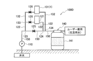
- a water purification system 100D according to a fourth embodiment will be described using FIG.
- the same components as those of the first embodiment are denoted by the same reference numerals, and redundant description will be omitted.
- the upstream side of the first bypass pipe 132 is connected to the second bypass pipe 122.
- the downstream side of the first bypass pipe 132 is connected to the main pipe 150.
- the downstream side of the second bypass pipe 122 is connected to the main pipe 150.
- the connecting portion 124 between the downstream side of the first bypass pipe 132 and the main pipe 150 is disposed at a different position from the connecting portion 134 between the downstream side of the second bypass pipe 122 and the main pipe 150.
- the upstream end of the second bypass pipe 122 is connected to the main pipe 150 at the connection portion 123.
- the downstream end of the second bypass pipe 122 is connected to the main pipe 150 at the connection portion 124.
- the upstream end of the first bypass pipe 132 is connected to the second bypass pipe 122 at the connection portion 133.
- the downstream end of the first bypass pipe 132 is connected to the main pipe 150 at the connection portion 134.
- the connecting portion 124 between the downstream side of the first bypass pipe 132 and the main pipe 150 is connected to a different position from the connecting portion 134 between the downstream side of the second bypass pipe 122 and the main pipe 150. . Therefore, the coagulant is hardly mixed in the second bypass pipe 122, and the reaction between the oxidizing agent and the coagulant can be suppressed. And since such a side reaction is suppressed, metal ions in the water to be treated can be sufficiently oxidized in the second bypass pipe 122.
- connection portion 124 between the downstream side of the first bypass pipe 132 and the main pipe 150 is preferably disposed upstream of the connection portion 134 between the downstream side of the second bypass pipe 122 and the main pipe 150.
- the metal ions in the water to be treated are more likely to be aggregated by the aggregating agent in the oxidized state. Therefore, with such an arrangement, the oxidized and colloidal metal component can be aggregated, and the removal efficiency of the turbid component can be improved.
- Embodiment 5 a water purification system 100E according to the fifth embodiment will be described with reference to FIG.
- symbol is attached
- a backflow prevention valve 137 is provided downstream of the coagulant supply device 131 in the first bypass pipe 132 to prevent backflow of the water to be treated.
- the water to be treated containing the oxidizing agent is a coagulant.
- Backflow to the supply device 131 can be prevented. Therefore, even when a material having a low resistance to the oxidizing agent is used for the film 6 of the coagulant supply device 131, it is possible to suppress the oxidative deterioration of the coagulant supply device 131. In addition, even in the case where harmful chlorine gas or the like is generated when the oxidizing agent and the coagulant react, the generation of such a gas can be suppressed.
- the water purification system concerning this embodiment is provided with the above-mentioned medicine supply device and the 1st bypass piping in which the medicine supply device was provided. Furthermore, the water purification system is a main component that is disposed in parallel with the first bypass pipe, and connects the pump disposed upstream with respect to the drug supply device and the filtration device disposed downstream with respect to the drug delivery device. It has piping.
- the water purification system according to the present embodiment uses the drug supply device according to the above embodiment, it is possible to supply a fixed amount of drug to the water to be treated without using an expensive device such as a metering pump. it can.
- Example 1 In Example 1, the ability to remove suspended solids was confirmed using the coagulant supply device 231 (drug supply device) shown in FIG. 12 and the water purification system 200 shown in FIG.
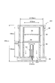
- the coagulant supply device 231 has substantially the same configuration as the medicine supply device 1A shown in FIG. 1 except that it has no pedestal.
- the height of the coagulant supply device 231 is 300 mm, and the inner diameter of the outer accommodation portion 60 is 125 mm.
- a coagulant supply device 231 is disposed inside the outer accommodation portion 60.
- the coagulant supply device 231 includes a drug storage unit 52 having an inner diameter of 52 mm and a height of 100 mm, and the drug storage unit 52 stores the drug 58.
- a liquid flocculant having a concentration of polyaluminum chloride of 11% was used.
- the drug containing portion 52 is provided with a membrane 56, and the average pore diameter of the pores of the membrane 56 is 0.45 ⁇ m.
- a mixing unit 54 having a height of 100 mm is provided below the medicine storage unit 52, and a water supply unit 53 having an inner diameter of 20 mm is provided inside the mixing unit 54.
- Water to be treated is supplied from the water supply unit 53 to the membrane 56 at a flow rate of 2.0 L / min, mixed with a coagulant in the mixing unit 54, and discharged from the discharge unit 55.
- the distance between the lower surface of the membrane 56 and the tip of the water supply unit 53 is 5 mm.
- the water purification system 200 includes a water storage tank 250 for storing treated water, an oxidant supply tank 221 for supplying an oxidant, a coagulant supply device 231 for supplying a coagulant, and a filtration device And 240.
- the water to be treated in the water storage tank 250 is supplied by the supply pump 210 at a flow rate of 2.0 L / min.
- the water to be treated is supplied to the coagulant supply device 231.
- the flowmeter 255 which measures the flow volume of to-be-processed water is installed upstream of the feed pump 210.
- Kaolin is added to the water to be treated in the water storage tank 250 so that the turbidity becomes 100 NTU (Nephelometric Turbidity Unit).
- the oxidizing agent supply tank 221 is provided on the upstream side of the coagulant supplying device 231 and on the downstream side of the supply pump 210, and the oxidizing agent is supplied from the metering pump 228 so that the chlorine concentration of the water to be treated is 10 ppm. Is supplied.
- the filtration device 240 is provided on the downstream side of the coagulant supply device 231.
- a cylindrical container having an inner diameter of 100 mm and a length of 715 mm is used.
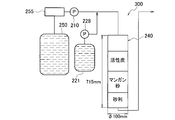
- Comparative Example 1 As shown in FIG. 14, a water purification system 300 was produced in the same manner as in Example 1 except that the coagulant supply device 231 was removed.
- Comparative Example 2 As shown in FIG. 15, the water purification system is carried out in the same manner as in Example 1 except that the coagulant is supplied to the water to be treated using the coagulant supply tank 239 and the metering pump 238 instead of the coagulant supply device 231. 400 was produced.
- the present invention it is possible to obtain a drug supply device capable of supplying a fixed amount of medicine to the water to be treated and a water purification system using the same without using an expensive device such as a metering pump.
Landscapes
- Chemical & Material Sciences (AREA)
- Organic Chemistry (AREA)
- Life Sciences & Earth Sciences (AREA)
- Hydrology & Water Resources (AREA)
- Engineering & Computer Science (AREA)
- Environmental & Geological Engineering (AREA)
- Water Supply & Treatment (AREA)
- Chemical Kinetics & Catalysis (AREA)
- Treatment Of Water By Oxidation Or Reduction (AREA)
- Separation Of Suspended Particles By Flocculating Agents (AREA)
Abstract
Un dispositif d'alimentation en produit chimique (1) est pourvu : d'un élément contenant une substance chimique (2) qui comprend une membrane (6) qu'un produit chimique (8) peut imprégner, et un support de membrane (7) pour soutenir la membrane (6), et qui est destinée à contenir le produit chimique (8); d'un élément d'alimentation en eau (3) pour acheminer l'eau à traiter vers la membrane (6); d'un élément de mélange (4) pour mélanger l'eau à traiter qui provient de l'élément d'alimentation en eau (3) et le produit chimique (8) qui a traversé la membrane (6); et d'un élément d'évacuation (5) pour évacuer l'eau traitée dans laquelle le produit chimique (8) a été mélangé.
Priority Applications (2)
| Application Number | Priority Date | Filing Date | Title |
|---|---|---|---|
| JP2019538955A JP6846660B2 (ja) | 2017-08-28 | 2018-04-25 | 薬剤供給装置及びそれを用いた水浄化システム |
| CN201880054797.XA CN111065604A (zh) | 2017-08-28 | 2018-04-25 | 药剂供给装置及使用该药剂供给装置的水净化系统 |
Applications Claiming Priority (2)
| Application Number | Priority Date | Filing Date | Title |
|---|---|---|---|
| JP2017-163419 | 2017-08-28 | ||
| JP2017163419 | 2017-08-28 |
Publications (1)
| Publication Number | Publication Date |
|---|---|
| WO2019044033A1 true WO2019044033A1 (fr) | 2019-03-07 |
Family
ID=65526236
Family Applications (1)
| Application Number | Title | Priority Date | Filing Date |
|---|---|---|---|
| PCT/JP2018/016708 Ceased WO2019044033A1 (fr) | 2017-08-28 | 2018-04-25 | Dispositif d'alimentation en produits chimiques et système de purification d'eau associé à ce dispositif |
Country Status (3)
| Country | Link |
|---|---|
| JP (1) | JP6846660B2 (fr) |
| CN (1) | CN111065604A (fr) |
| WO (1) | WO2019044033A1 (fr) |
Cited By (1)
| Publication number | Priority date | Publication date | Assignee | Title |
|---|---|---|---|---|
| WO2020262140A1 (fr) * | 2019-06-26 | 2020-12-30 | パナソニックIpマネジメント株式会社 | Dispositif d'alimentation en agent chimique |
Citations (9)
| Publication number | Priority date | Publication date | Assignee | Title |
|---|---|---|---|---|
| JPS6151994U (fr) * | 1984-09-05 | 1986-04-08 | ||
| JPH09187777A (ja) * | 1995-11-02 | 1997-07-22 | Toto Ltd | 飲料水改質装置 |
| US5810043A (en) * | 1997-04-14 | 1998-09-22 | Magi-Eau Inc. | Automatic chlorinator |
| JP2003261975A (ja) * | 2002-03-11 | 2003-09-19 | Toto Ltd | 徐放装置 |
| JP2005021765A (ja) * | 2003-06-30 | 2005-01-27 | Touzai Kagaku Sangyo Kk | 水処理方法 |
| JP2010274148A (ja) * | 2009-05-26 | 2010-12-09 | Panasonic Electric Works Co Ltd | 水処理装置 |
| JP2015013267A (ja) * | 2013-07-08 | 2015-01-22 | 株式会社セパシグマ | 混合撹拌滞留装置 |
| JP2015213891A (ja) * | 2014-05-13 | 2015-12-03 | パナソニックIpマネジメント株式会社 | 薬剤供給装置 |
| JP2017131798A (ja) * | 2016-01-25 | 2017-08-03 | パナソニックIpマネジメント株式会社 | 水処理装置 |
Family Cites Families (8)
| Publication number | Priority date | Publication date | Assignee | Title |
|---|---|---|---|---|
| JPH09187681A (ja) * | 1995-11-02 | 1997-07-22 | Toto Ltd | 薬剤徐放機能付シャワーヘッド及び薬剤徐放カートリッジ |
| JPH09184179A (ja) * | 1995-11-02 | 1997-07-15 | Toto Ltd | 薬剤徐放機能付便器 |
| JPH09184181A (ja) * | 1995-11-02 | 1997-07-15 | Toto Ltd | 温水洗浄便座 |
| JPH09187680A (ja) * | 1995-11-02 | 1997-07-22 | Toto Ltd | 洗浄剤徐放機能付洗面所用水栓 |
| JP2001300357A (ja) * | 1995-11-02 | 2001-10-30 | Toto Ltd | 薬剤除放機能付シャワーヘッド及び薬剤除放カートリッジ |
| JPH09184690A (ja) * | 1995-11-02 | 1997-07-15 | Toto Ltd | 空調用クーリングタワー |
| JPH09182684A (ja) * | 1995-11-02 | 1997-07-15 | Toto Ltd | 薬剤徐放装置を備える水槽 |
| US9309138B2 (en) * | 2009-08-21 | 2016-04-12 | Toray Industries, Inc. | Fresh water production method |
-
2018
- 2018-04-25 CN CN201880054797.XA patent/CN111065604A/zh active Pending
- 2018-04-25 WO PCT/JP2018/016708 patent/WO2019044033A1/fr not_active Ceased
- 2018-04-25 JP JP2019538955A patent/JP6846660B2/ja not_active Expired - Fee Related
Patent Citations (9)
| Publication number | Priority date | Publication date | Assignee | Title |
|---|---|---|---|---|
| JPS6151994U (fr) * | 1984-09-05 | 1986-04-08 | ||
| JPH09187777A (ja) * | 1995-11-02 | 1997-07-22 | Toto Ltd | 飲料水改質装置 |
| US5810043A (en) * | 1997-04-14 | 1998-09-22 | Magi-Eau Inc. | Automatic chlorinator |
| JP2003261975A (ja) * | 2002-03-11 | 2003-09-19 | Toto Ltd | 徐放装置 |
| JP2005021765A (ja) * | 2003-06-30 | 2005-01-27 | Touzai Kagaku Sangyo Kk | 水処理方法 |
| JP2010274148A (ja) * | 2009-05-26 | 2010-12-09 | Panasonic Electric Works Co Ltd | 水処理装置 |
| JP2015013267A (ja) * | 2013-07-08 | 2015-01-22 | 株式会社セパシグマ | 混合撹拌滞留装置 |
| JP2015213891A (ja) * | 2014-05-13 | 2015-12-03 | パナソニックIpマネジメント株式会社 | 薬剤供給装置 |
| JP2017131798A (ja) * | 2016-01-25 | 2017-08-03 | パナソニックIpマネジメント株式会社 | 水処理装置 |
Cited By (1)
| Publication number | Priority date | Publication date | Assignee | Title |
|---|---|---|---|---|
| WO2020262140A1 (fr) * | 2019-06-26 | 2020-12-30 | パナソニックIpマネジメント株式会社 | Dispositif d'alimentation en agent chimique |
Also Published As
| Publication number | Publication date |
|---|---|
| JPWO2019044033A1 (ja) | 2020-09-03 |
| CN111065604A (zh) | 2020-04-24 |
| JP6846660B2 (ja) | 2021-03-24 |
Similar Documents
| Publication | Publication Date | Title |
|---|---|---|
| JP5843071B2 (ja) | 水処理装置 | |
| JP2012239947A (ja) | 水処理方法および水処理装置 | |
| Aly et al. | In-line coagulation assessment for ultrafiltration fouling reduction to treat secondary effluent for water reuse | |
| US12358822B2 (en) | Ferrate based water treatment | |
| WO2004071971A1 (fr) | Dispositif de filtre de traitement d'eau et appareil de traitement d'eau | |
| US20150144491A1 (en) | Solid-liquid separation method | |
| JP6846660B2 (ja) | 薬剤供給装置及びそれを用いた水浄化システム | |
| JP6846656B2 (ja) | 水処理装置 | |
| JP2018061921A (ja) | 水浄化システム | |
| EP3062906B1 (fr) | Système de traitement de fluide | |
| CN101891337B (zh) | 将劣v类地表水处理为生活饮用水的处理系统及方法 | |
| JP2005279614A (ja) | 浄水装置 | |
| WO2019038994A1 (fr) | Dispositif de traitement d'eau et système de traitement d'eau | |
| WO2019106752A1 (fr) | Système de purification d'eau | |
| CN118055803A (zh) | 在膜过滤系统中定量给料混凝剂和吸附剂的方法 | |
| JP7824914B2 (ja) | 純水用水の製造方法及び製造装置、純水製造方法及び純水製造システム | |
| JP2019103955A (ja) | 水処理システム | |
| WO2021149581A1 (fr) | Dispositif de purification d'eau et procédé de purification d'eau | |
| WO2018155120A1 (fr) | Procédé de fabrication de charbon actif supportant du fer pour dispositif de traitement d'eau | |
| JP2018114490A (ja) | リン含有高硬度水の浄化方法及び浄化装置 | |
| JP2026010098A (ja) | 純水用水の製造方法及び製造装置、純水製造方法及び純水製造システム | |
| CN110482755A (zh) | 微酸性次氯酸水生产设备 | |
| JP5174548B2 (ja) | 複合ろ過設備の運転方法 | |
| CN119461692A (zh) | 纯水用水的制造方法及制造装置、纯水制造方法及系统 | |
| JP2024049431A (ja) | 水浄化装置 |
Legal Events
| Date | Code | Title | Description |
|---|---|---|---|
| 121 | Ep: the epo has been informed by wipo that ep was designated in this application |
Ref document number: 18852142 Country of ref document: EP Kind code of ref document: A1 |
|
| ENP | Entry into the national phase |
Ref document number: 2019538955 Country of ref document: JP Kind code of ref document: A |
|
| NENP | Non-entry into the national phase |
Ref country code: DE |
|
| 122 | Ep: pct application non-entry in european phase |
Ref document number: 18852142 Country of ref document: EP Kind code of ref document: A1 |