WO2019044582A1 - Bloc de batteries et module de batterie le comportant - Google Patents
Bloc de batteries et module de batterie le comportant Download PDFInfo
- Publication number
- WO2019044582A1 WO2019044582A1 PCT/JP2018/030773 JP2018030773W WO2019044582A1 WO 2019044582 A1 WO2019044582 A1 WO 2019044582A1 JP 2018030773 W JP2018030773 W JP 2018030773W WO 2019044582 A1 WO2019044582 A1 WO 2019044582A1
- Authority
- WO
- WIPO (PCT)
- Prior art keywords
- battery
- negative electrode
- positive electrode
- bus bar
- batteries
- Prior art date
- Legal status (The legal status is an assumption and is not a legal conclusion. Google has not performed a legal analysis and makes no representation as to the accuracy of the status listed.)
- Ceased
Links
Images


Classifications
-
- H—ELECTRICITY
- H01—ELECTRIC ELEMENTS
- H01M—PROCESSES OR MEANS, e.g. BATTERIES, FOR THE DIRECT CONVERSION OF CHEMICAL ENERGY INTO ELECTRICAL ENERGY
- H01M50/00—Constructional details or processes of manufacture of the non-active parts of electrochemical cells other than fuel cells, e.g. hybrid cells
- H01M50/30—Arrangements for facilitating escape of gases
-
- H—ELECTRICITY
- H01—ELECTRIC ELEMENTS
- H01M—PROCESSES OR MEANS, e.g. BATTERIES, FOR THE DIRECT CONVERSION OF CHEMICAL ENERGY INTO ELECTRICAL ENERGY
- H01M50/00—Constructional details or processes of manufacture of the non-active parts of electrochemical cells other than fuel cells, e.g. hybrid cells
- H01M50/20—Mountings; Secondary casings or frames; Racks, modules or packs; Suspension devices; Shock absorbers; Transport or carrying devices; Holders
- H01M50/204—Racks, modules or packs for multiple batteries or multiple cells
- H01M50/207—Racks, modules or packs for multiple batteries or multiple cells characterised by their shape
- H01M50/213—Racks, modules or packs for multiple batteries or multiple cells characterised by their shape adapted for cells having curved cross-section, e.g. round or elliptic
-
- H—ELECTRICITY
- H01—ELECTRIC ELEMENTS
- H01M—PROCESSES OR MEANS, e.g. BATTERIES, FOR THE DIRECT CONVERSION OF CHEMICAL ENERGY INTO ELECTRICAL ENERGY
- H01M50/00—Constructional details or processes of manufacture of the non-active parts of electrochemical cells other than fuel cells, e.g. hybrid cells
- H01M50/20—Mountings; Secondary casings or frames; Racks, modules or packs; Suspension devices; Shock absorbers; Transport or carrying devices; Holders
- H01M50/271—Lids or covers for the racks or secondary casings
-
- H—ELECTRICITY
- H01—ELECTRIC ELEMENTS
- H01M—PROCESSES OR MEANS, e.g. BATTERIES, FOR THE DIRECT CONVERSION OF CHEMICAL ENERGY INTO ELECTRICAL ENERGY
- H01M50/00—Constructional details or processes of manufacture of the non-active parts of electrochemical cells other than fuel cells, e.g. hybrid cells
- H01M50/30—Arrangements for facilitating escape of gases
- H01M50/35—Gas exhaust passages comprising elongated, tortuous or labyrinth-shaped exhaust passages
-
- H—ELECTRICITY
- H01—ELECTRIC ELEMENTS
- H01M—PROCESSES OR MEANS, e.g. BATTERIES, FOR THE DIRECT CONVERSION OF CHEMICAL ENERGY INTO ELECTRICAL ENERGY
- H01M50/00—Constructional details or processes of manufacture of the non-active parts of electrochemical cells other than fuel cells, e.g. hybrid cells
- H01M50/50—Current conducting connections for cells or batteries
- H01M50/502—Interconnectors for connecting terminals of adjacent batteries; Interconnectors for connecting cells outside a battery casing
- H01M50/505—Interconnectors for connecting terminals of adjacent batteries; Interconnectors for connecting cells outside a battery casing comprising a single busbar
-
- H—ELECTRICITY
- H01—ELECTRIC ELEMENTS
- H01M—PROCESSES OR MEANS, e.g. BATTERIES, FOR THE DIRECT CONVERSION OF CHEMICAL ENERGY INTO ELECTRICAL ENERGY
- H01M50/00—Constructional details or processes of manufacture of the non-active parts of electrochemical cells other than fuel cells, e.g. hybrid cells
- H01M50/50—Current conducting connections for cells or batteries
- H01M50/502—Interconnectors for connecting terminals of adjacent batteries; Interconnectors for connecting cells outside a battery casing
- H01M50/509—Interconnectors for connecting terminals of adjacent batteries; Interconnectors for connecting cells outside a battery casing characterised by the type of connection, e.g. mixed connections
- H01M50/512—Connection only in parallel
-
- H—ELECTRICITY
- H01—ELECTRIC ELEMENTS
- H01M—PROCESSES OR MEANS, e.g. BATTERIES, FOR THE DIRECT CONVERSION OF CHEMICAL ENERGY INTO ELECTRICAL ENERGY
- H01M50/00—Constructional details or processes of manufacture of the non-active parts of electrochemical cells other than fuel cells, e.g. hybrid cells
- H01M50/50—Current conducting connections for cells or batteries
- H01M50/572—Means for preventing undesired use or discharge
- H01M50/574—Devices or arrangements for the interruption of current
- H01M50/583—Devices or arrangements for the interruption of current in response to current, e.g. fuses
-
- H—ELECTRICITY
- H01—ELECTRIC ELEMENTS
- H01M—PROCESSES OR MEANS, e.g. BATTERIES, FOR THE DIRECT CONVERSION OF CHEMICAL ENERGY INTO ELECTRICAL ENERGY
- H01M50/00—Constructional details or processes of manufacture of the non-active parts of electrochemical cells other than fuel cells, e.g. hybrid cells
- H01M50/50—Current conducting connections for cells or batteries
- H01M50/572—Means for preventing undesired use or discharge
- H01M50/584—Means for preventing undesired use or discharge for preventing incorrect connections inside or outside the batteries
- H01M50/59—Means for preventing undesired use or discharge for preventing incorrect connections inside or outside the batteries characterised by the protection means
-
- H—ELECTRICITY
- H01—ELECTRIC ELEMENTS
- H01M—PROCESSES OR MEANS, e.g. BATTERIES, FOR THE DIRECT CONVERSION OF CHEMICAL ENERGY INTO ELECTRICAL ENERGY
- H01M10/00—Secondary cells; Manufacture thereof
- H01M10/60—Heating or cooling; Temperature control
- H01M10/65—Means for temperature control structurally associated with the cells
- H01M10/658—Means for temperature control structurally associated with the cells by thermal insulation or shielding
-
- H—ELECTRICITY
- H01—ELECTRIC ELEMENTS
- H01M—PROCESSES OR MEANS, e.g. BATTERIES, FOR THE DIRECT CONVERSION OF CHEMICAL ENERGY INTO ELECTRICAL ENERGY
- H01M2200/00—Safety devices for primary or secondary batteries
- H01M2200/10—Temperature sensitive devices
- H01M2200/103—Fuse
-
- Y—GENERAL TAGGING OF NEW TECHNOLOGICAL DEVELOPMENTS; GENERAL TAGGING OF CROSS-SECTIONAL TECHNOLOGIES SPANNING OVER SEVERAL SECTIONS OF THE IPC; TECHNICAL SUBJECTS COVERED BY FORMER USPC CROSS-REFERENCE ART COLLECTIONS [XRACs] AND DIGESTS
- Y02—TECHNOLOGIES OR APPLICATIONS FOR MITIGATION OR ADAPTATION AGAINST CLIMATE CHANGE
- Y02E—REDUCTION OF GREENHOUSE GAS [GHG] EMISSIONS, RELATED TO ENERGY GENERATION, TRANSMISSION OR DISTRIBUTION
- Y02E60/00—Enabling technologies; Technologies with a potential or indirect contribution to GHG emissions mitigation
- Y02E60/10—Energy storage using batteries
Definitions
- the present invention relates to a battery block in which a plurality of battery packs are arranged in parallel in units of a battery pack including a plurality of batteries.
- a battery module in which a plurality of batteries are connected in parallel to form a battery block, and a plurality of battery blocks are connected in series to output predetermined voltages and capacities.
- the positive electrode terminal and the negative electrode terminal are provided at one end of the battery, and the positive electrode terminal and the negative electrode terminal of the plurality of batteries are connected in parallel to the positive and negative busbars arranged on the one end of the battery.
- the described battery block is described.
- the positive and negative bus bars are stacked through the insulating plate, and the holes are respectively provided in the bus bar and the insulating plate, and through the holes, the upper layer bus bar is connected to the positive electrode terminal of the battery. Or the negative electrode terminal is connected.
- the positive and negative bus bars stacked via the insulating plate become flat plates covering all the batteries, so that the area is increased. There is a problem that the cost is high.
- the present invention has been made in view of the above problems, and a main object of the present invention is to provide a battery block capable of reducing manufacturing cost and material cost in a battery block in which a plurality of batteries are connected in parallel. is there.
- a battery block according to the present invention is a battery block in which a plurality of assembled batteries are arranged in parallel in units of a assembled battery composed of a plurality of batteries, and the batteries are electrically isolated from each other at one end thereof
- the battery assembly has a plurality of batteries arranged in a line, with the direction of one end aligned, and an insulating property disposed on one end of the battery to hold the battery.
- a positive electrode bus bar disposed on one end of the battery to connect the positive electrode terminals of the plurality of batteries in parallel and a negative electrode bus bar connecting the negative electrodes of the plurality of batteries in parallel.
- Each of the insulating holders is held by holding portions formed in parallel with each other along the column direction.
- the battery block which can aim at reduction of manufacturing cost and material cost can be provided in the battery block to which the several battery was connected in parallel.
- FIG. 1 It is the perspective view which showed typically the structure of the battery block in one Embodiment of this invention.
- (A) to (d) are exploded views of the battery block in the present embodiment. It is a sectional view showing an example of a battery which constitutes an assembled battery.
- (A), (b) is the figure which showed typically the structure of the positive electrode bus-bar in this embodiment.
- (A), (b) is the figure which showed typically the structure of the negative electrode bus-bar in this embodiment.
- (A), (b) is the elements on larger scale which showed the state in which the positive electrode connection piece of a positive electrode bus-bar and the negative electrode connection piece of a negative electrode bus-bar were connected to the positive electrode terminal and negative electrode terminal of a battery, respectively.
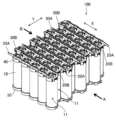
- FIG. 1 is a perspective view schematically showing the configuration of a battery block 100 according to an embodiment of the present invention. Moreover, FIG. 2 is an exploded view of the battery block 100 in this embodiment.
- the battery block 100 in the present embodiment has a configuration in which a plurality of the assembled batteries 11 are arranged in parallel in units of the assembled battery 11 composed of the plurality of batteries 10.
- the battery pack 11 five batteries 10 are arranged in a line in the X direction, and a battery block 100 is formed.
- eight assembled batteries 11 are arranged in parallel in the Y direction is illustrated, the present invention is not limited thereto.
- the battery 10 which comprises the assembled battery 11 has the positive electrode terminal 5 and the negative electrode terminal 6 which were mutually electrically insulated mutually at the one end part, as shown in FIG.2 (c). Further, in the battery assembly 11, the plurality of batteries 10 are arranged in a line in the X direction, with the direction of one end aligned.
- the battery assembly 11 is provided on one end side of the battery 10 and includes an insulating holder 40 for holding the battery 10. Then, as shown in FIG. 2B, holding portions 41 and 42 formed in parallel to each other are formed in the insulating holder 40 along the column direction (X direction).
- the insulating holder 40 disposed for each of the battery packs 11 is integrally formed as the entire battery block 100. However, the insulating holder 40 may be formed separately for each of the battery packs 11. Good.
- the assembled battery 11 includes a positive electrode bus bar 20B (20A) in which the positive electrode terminals 5 of the plurality of batteries 10 are connected in parallel on one end of the battery 10; A negative bus bar 30A (30B) is provided to connect the negative terminals 6 in parallel.
- positive electrode bus bar 20B (20B) and negative electrode bus bar 30A (30B) are held by holding parts 41 and 42 formed in insulating holder 40, respectively.
- the positive electrode bus bar 20B (20A) and the negative electrode bus bar 30A (30B) are arranged in parallel along the column direction (X direction) on both sides of the battery 10.
- the plurality of batteries 10 constituting the battery pack 11 are arranged in a staggered manner. Therefore, in adjacent battery packs 11, if the lengths of positive electrode bus bar 20B and negative electrode bus bar 30A used for one battery group 11 and the positive electrode bus bars 20A and negative electrode bus bar 30B used for the other battery group 11 are different I'm sorry.
- the cell holder 50 is disposed, and by inserting each battery 10 into the hole 50a formed in the cell holder 50, each battery 10 can be It is held by the cell holder 50.
- the cell holder 50 is integrally formed as the battery block 100 whole.
- a cylindrical lithium ion secondary battery as shown in FIG. 3 can be used as the battery 10 constituting the assembled battery 11.
- an electrode group in which a positive electrode 1 and a negative electrode 2 are wound via a separator 3 is accommodated in a battery case 6 together with a non-aqueous electrolyte (not shown).
- Insulating plates 9a and 9b are disposed on the upper and lower sides of the electrode group, the positive electrode 1 is joined to the filter 8a through the positive electrode lead 4a, and the negative electrode 2 is a battery case 6 which doubles as a negative electrode terminal through the negative electrode lead 4b. It is joined to the bottom.
- the filter 8a is connected to the inner cap 8b, and the projection of the inner cap 8b is joined to the metal valve body 8c. Furthermore, the valve body 8c is connected to the sealing plate 5 which doubles as a positive electrode terminal.
- the sealing plate 5, the valve body 8c, the inner cap 8b, and the filter 8a are integrated to seal the opening of the battery case 6 via the gasket 7. Further, the sealing plate 5 is formed with an open portion 5 a for discharging the gas generated in the battery 10 to the outside.
- FIG. 4 is a view schematically showing the configuration of the positive electrode bus bar in the present embodiment, where (a) is the longer positive electrode bus bar 20A and (b) is the shorter positive electrode bus bar 20B.
- the positive electrode bus bar 20A is composed of a bus bar main body 21A and a plurality of (five in this case) positive electrode current collector plates 22 connected to the positive electrode terminal of each battery, the bus bar main body 21A and the positive electrode The current collector plate 22 is joined by ultrasonic welding or the like.
- the positive electrode bus bar 20B is composed of a bus bar main body 21B and a positive electrode current collector plate 22 having a plurality of positive electrode connection pieces 23 connected to the positive electrode terminal of each battery, and the bus bar main body 21B and the positive electrode current collector plate 22 And are joined by ultrasonic welding or the like.
- the bus bar main body 21A is longer than the bus bar main body 21B, the positive electrode current collector plate 22 has the same configuration.
- FIG. 5 is a view schematically showing the configuration of the negative electrode bus bar in the present embodiment, where (a) is the longer negative electrode bus bar 30A and (b) is the shorter negative electrode bus bar 30B.
- the negative electrode bus bar 30A includes the bus bar main body 31A and the negative electrode current collector plate 32 having the plurality of negative electrode connection pieces 33 connected to the negative electrode terminal of each battery.
- the electric plate 32 is joined by ultrasonic welding or the like.
- negative bus bar 30B is formed of bus bar main body 31B and negative current collector plate 32 having a plurality of negative electrode connection pieces 33 connected to the negative electrode terminal of each battery, and bus bar main body 31B and negative current collector plate 32. And are joined by ultrasonic welding or the like.
- the bus bar main body 31A is longer than the bus bar main body 31B, the negative electrode current collector plate 32 has the same configuration.
- the bus bar main bodies (21A, 21B), (31A, 31B) have a thickness and a width corresponding to the current capacity when the plurality of cells 10 constituting the battery assembly 11 are connected in parallel.
- the positive electrode current collector 22 and the positive electrode connection piece 23, and the negative electrode current collector 32 and the negative electrode connection piece 33 are integrally formed, and the positive electrode connection piece 23 and the negative electrode connection piece 33 are positive electrodes of the battery 10. It has a flexible thickness so as to be easily connected to the terminal 5 and the negative electrode terminal 6.
- the materials of the bus bar main bodies (21A, 21B), (31A, 31B), the positive electrode current collector 22 (positive electrode connection piece 23), and the negative electrode current collector 32 (negative electrode connection piece 33) are not particularly limited. Aluminum or the like can be used.
- FIG. 6A and 6B show that the positive electrode connection piece 23 of the positive electrode bus bar 20B and the negative electrode connection piece 33 of the negative electrode bus bar 30B of the assembled battery 11 arranged at the end are the positive electrode terminal 5 of the battery 10 respectively.
- 6 is a partially enlarged view showing a state of being connected to the negative electrode terminal 6.
- FIG. 6A is a perspective view as viewed in the direction of arrow A in FIG. 1
- FIG. 6B is a perspective view as viewed in the direction of arrow B.
- the insulating holder 40 is omitted.
- the positive electrode connection piece 23 of the positive electrode bus-bar 20B is joined to the positive electrode terminal 5 of the battery 10 by laser welding etc., for example.
- the negative electrode connection piece 33 of the negative electrode bus bar 30B is joined to the negative electrode terminal 6 of the battery 10 by, for example, laser welding or the like.
- the negative electrode connection piece 33 is joined to the shoulder portion 6A of the battery case 6 shown in FIG. 3, but may be joined to the side wall of the battery case 6.
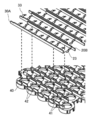
- FIG. 7 is a view showing a method of holding the positive electrode bus bar 20B and the negative electrode bus bar 30A in the holding portions 41 and 42 formed on the insulating holder 40, respectively, in the assembled battery 11 arranged at the end.
- the holding portion 41 for holding the positive electrode bus bar 20B and the holding portion 42 for holding the negative electrode bus bar 30A are parallel to each other along the row direction of the batteries 10 constituting the assembled battery 11. It is formed.
- the holding portions 41 and 42 are respectively formed of ribs arranged alternately, and the positive electrode bus bar 20B and the negative electrode bus bar 30A are inserted into and held in the gaps between the ribs.
- the shape of the holding portions 41 and 42 is not particularly limited.
- the holding portions 41 and 42 are positive electrode bus bars And in the state which hold
- the holding portions 41 and 42 are respectively configured by the ribs arranged alternately, but may be configured, for example, by mutually parallel ribs having a certain gap. Further, the insulating holder 40 and the holding portions 41 and 42 may be integrally formed of separate members.
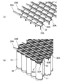
- FIG. 8 illustrates a method of connecting battery packs 11 in parallel, taking a battery block as an example in which eight battery packs 11 in which five batteries 10 are arranged in a row in the X direction are arranged in parallel in the Y direction. It is the top view shown.
- the batteries 10 constituting the assembled battery 11 are connected in parallel by the positive electrode bus bar 20A (20B) and the negative electrode bus bar 30A (30B) provided independently for each assembled battery 11. Therefore, in order to connect all the batteries 10 constituting the battery block in parallel, it is necessary to connect the assembled batteries 11 in parallel.
- the adjacent battery packs 11A and 11B the plurality of cells 10 constituting each of the battery packs 11A and 11B are arranged in a zigzag. Therefore, in the arrangement direction (X direction) of the plurality of batteries 10 constituting the assembled battery 11, the adjacent assembled batteries 11A and 11B respectively project in opposite directions.
- the positive electrode bus bars 20A and 20B in each of the assembled batteries 11A are extended to one end of the arrangement direction (X direction) of the batteries 10, and the negative bus bars 30A and 30B in each of the assembled batteries 11B are arranged in the arrangement direction of the batteries 10 Extend to the other end of (X direction).
- positive electrode bus bars 20A and 20B and negative electrode bus bars 30A and 30B provided independently for each of assembled batteries 11A and 11B constitute assembled battery 11 at both ends in the arrangement direction (X direction) of batteries 10, respectively.
- the parallel connection can be performed by the connection bus bars 60 and 70 disposed in the direction (Y direction) perpendicular to the arrangement direction (X direction) of the plurality of batteries 10.
- the positive electrode bus bars 20A and 20B, the negative electrode bus bars 30A and 30B, and the connection bus bars 60 and 70 can be joined by, for example, laser welding.
- a battery block 100 is configured by arranging a plurality of battery packs 11 in parallel in units of a battery pack 11 composed of a plurality of batteries 10, and connecting all the batteries 10 constituting the battery block 100 in parallel. ing. Therefore, a battery module having a predetermined voltage and capacity can be configured by arranging a plurality of the battery blocks 100 and connecting the adjacent battery blocks 100 in series with each other.
- the battery block 100 is configured by arranging a plurality of the battery packs 11 in parallel in units of the battery pack 11 in which the plurality of batteries 10 are connected in parallel. Even if the arrangement of the assembled batteries 11 is changed, the assembled batteries 11 can be connected in parallel only by changing the lengths of the connecting bus bars 60 and 70. This makes it possible to reduce the manufacturing cost of the battery block 100 of various specifications.
- parallel connection of the plurality of batteries 10 constituting the battery assembly 11 is performed by the positive electrode bus bars 20A and 20B and the negative electrode bus bars 30A and 30B disposed on one end of the battery 10, Since the parallel connection of the assembled batteries 11 is performed by the connecting bus bars 60 and 70 disposed in the direction perpendicular to the arrangement direction of the plurality of batteries 10 constituting the assembled battery 11, the battery can be made with a minimum number of members. Parallel connection of all the batteries 10 which comprise block 100 can be performed. Thereby, the material cost of the battery block 100 can be reduced.
- the positive electrode bus bars 20A and 20B and the negative electrode bus bars 30A and 30B are provided independently for each of the assembled batteries 11, depending on the number of the batteries 10 constituting the assembled battery 11,
- the positive electrode bus bars 20A and 20B and the negative electrode bus bars 30A and 30B suitable for the current capacity can be designed. Thereby, the material cost of positive electrode bus bars 20A and 20B and negative electrode bus bars 30A and 30B can be reduced.
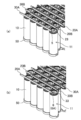
- FIG. 9 is a perspective view schematically showing the configuration of a battery block 100 according to another embodiment of the present invention.
- the battery block 100 in the present embodiment has a configuration in which one end of the battery 10 is covered with a lid 80. At this time, since the positive electrode bus bars 20A and 20B and the negative electrode bus bars 30A and 30B provided in each of the assembled batteries 11 are positioned above one end of the battery 10, the lid 80 and the positive electrode bus bars 20A and 20B are provided. A constant space is defined by the side walls of the row negative electrode bus bars 30A and 30B.
- the sealing plate 5 is provided with the open portion 5 a for discharging the gas generated in the battery 10 to the outside. Therefore, the space partitioned by the lid 80 and the side walls of the positive electrode bus bars 20A and 20B and the negative electrode bus bars 30A and 30B can be used as an exhaust duct for discharging the gas ejected from the battery 10 to the outside.
- gas is generated by heat generation due to internal short circuit etc. in the battery 10, and even if high temperature gas is ejected from the battery 10, the high temperature gas is directed in the direction of the arrow through the exhaust duct. Can be discharged to the outside of the battery block 100.
- FIG. 10A is a view schematically showing the configuration of the negative electrode bus bar 30B in another embodiment of the present invention.
- FIG. 10B is a view showing a state in which the negative electrode connection piece 33 of the negative electrode bus bar 30B is connected to the negative electrode terminal 6 (6A) of the battery 10.
- the insulating holder 4 is omitted.
- the negative electrode connection piece 33 of the negative electrode bus bar 30B in the present embodiment has a fuse portion 33A with a narrowed width in a part thereof.
- the fuse portion 33A is formed to be folded back and forth along the side surface of the battery 10 so as not to contact the battery case 6. Thereby, the length which provides fuse part 33A in negative electrode connection piece 33 can be secured, and when abnormality occurs in battery 10, abnormality occurs because fuse part 33A connected to battery 10 is melted and broken by overcurrent.
- the battery 10 can be electrically isolated from the other batteries 10.
- the shape of the fuse portion 33A in the present embodiment is not particularly limited as long as it is a portion formed so as to have a larger electrical resistance than the other portions of the negative electrode connection piece 33.
- each battery 10 in the adjacent battery packs 11, the plurality of batteries 10 constituting each of the battery packs 11 are arranged in a zigzag, but each battery 10 is arranged in the arrangement direction (X direction) of the batteries 10. It may be arranged in line in the vertical direction (Y direction).
- a cylindrical lithium ion secondary battery is exemplified as the battery 10 constituting the assembled battery 11, but the present invention is not limited to this.
- the positive electrode terminal electrically isolated from each other at one end portion As long as it is a battery having a negative electrode terminal, its type, shape, etc. do not matter.
Landscapes
- Chemical & Material Sciences (AREA)
- Chemical Kinetics & Catalysis (AREA)
- Electrochemistry (AREA)
- General Chemical & Material Sciences (AREA)
- Connection Of Batteries Or Terminals (AREA)
- Battery Mounting, Suspending (AREA)
- Gas Exhaust Devices For Batteries (AREA)
Abstract
L'invention concerne un bloc de batteries comprenant une pluralité de blocs-batteries agencés en parallèle comme des unités composées d'une pluralité de batteries, les batteries présentant une borne d'électrode positive et une borne d'électrode négative à une première extrémité, et les blocs-batteries étant pourvus : de la pluralité de batteries agencées en une seule ligne en alignant les directions des premières extrémités ; d'un support d'isolation disposé d'un côté d'extrémité des batteries et qui maintient les batteries ; et d'une barre omnibus d'électrode positive servant à connecter des bornes d'électrode positive de la pluralité de batteries en parallèle, et d'une barre omnibus d'électrode négative servant à connecter des bornes d'électrode négative de la pluralité de batteries en parallèle, les barres omnibus étant disposées sur la première extrémité des batteries et maintenues dans des parties de maintien formées parallèles l'une à l'autre dans la direction d'alignement dans le support d'isolation.
Priority Applications (3)
| Application Number | Priority Date | Filing Date | Title |
|---|---|---|---|
| CN201880052373.XA CN111033807B (zh) | 2017-08-31 | 2018-08-21 | 电池块以及具备该电池块的电池模块 |
| US16/638,899 US11600878B2 (en) | 2017-08-31 | 2018-08-21 | Battery block and battery module provided with same |
| JP2019539387A JP7165897B2 (ja) | 2017-08-31 | 2018-08-21 | 電池ブロック及びそれを備えた電池モジュール |
Applications Claiming Priority (2)
| Application Number | Priority Date | Filing Date | Title |
|---|---|---|---|
| JP2017-166335 | 2017-08-31 | ||
| JP2017166335 | 2017-08-31 |
Publications (1)
| Publication Number | Publication Date |
|---|---|
| WO2019044582A1 true WO2019044582A1 (fr) | 2019-03-07 |
Family
ID=65524953
Family Applications (1)
| Application Number | Title | Priority Date | Filing Date |
|---|---|---|---|
| PCT/JP2018/030773 Ceased WO2019044582A1 (fr) | 2017-08-31 | 2018-08-21 | Bloc de batteries et module de batterie le comportant |
Country Status (4)
| Country | Link |
|---|---|
| US (1) | US11600878B2 (fr) |
| JP (1) | JP7165897B2 (fr) |
| CN (1) | CN111033807B (fr) |
| WO (1) | WO2019044582A1 (fr) |
Cited By (13)
| Publication number | Priority date | Publication date | Assignee | Title |
|---|---|---|---|---|
| GB2597248A (en) * | 2020-07-16 | 2022-01-26 | Rolls Royce Plc | Battery assembly |
| WO2022070972A1 (fr) * | 2020-09-30 | 2022-04-07 | パナソニックIpマネジメント株式会社 | Module de stockage d'énergie électrique |
| JP2022529444A (ja) * | 2019-04-15 | 2022-06-22 | ロベルト・ボッシュ・ゲゼルシャフト・ミト・ベシュレンクテル・ハフツング | 非対称セル電気接続を含む電池モジュール |
| JPWO2022196451A1 (fr) * | 2021-03-19 | 2022-09-22 | ||
| KR20220134474A (ko) * | 2021-03-26 | 2022-10-05 | 주식회사 엘지에너지솔루션 | 배터리 팩, 그리고 이를 포함하는 자동차 |
| WO2022220549A1 (fr) * | 2021-04-13 | 2022-10-20 | 한화솔루션 주식회사 | Module d'élément de batterie |
| JP2023501735A (ja) * | 2020-06-16 | 2023-01-18 | エルジー エナジー ソリューション リミテッド | バッテリーパック、それを含む電子デバイス及び自動車 |
| KR20230025118A (ko) * | 2021-08-13 | 2023-02-21 | 주식회사 엘지에너지솔루션 | 활성화 트레이 및 이를 이용한 활성화 트레이 적층체 |
| JP2023044145A (ja) * | 2021-09-17 | 2023-03-30 | 豊田合成株式会社 | 電池パック |
| JP2023044141A (ja) * | 2021-09-17 | 2023-03-30 | 豊田合成株式会社 | 電池パック |
| JP2023044147A (ja) * | 2021-09-17 | 2023-03-30 | 豊田合成株式会社 | 電池パック |
| WO2024024420A1 (fr) * | 2022-07-28 | 2024-02-01 | パナソニックIpマネジメント株式会社 | Bloc-batterie |
| EP4191773A4 (fr) * | 2020-07-31 | 2025-01-01 | Panasonic Intellectual Property Management Co., Ltd. | Module de stockage d'électricité |
Families Citing this family (14)
| Publication number | Priority date | Publication date | Assignee | Title |
|---|---|---|---|---|
| KR102204303B1 (ko) * | 2017-10-27 | 2021-01-15 | 주식회사 엘지화학 | 전지 셀 냉각 및 고정 구조가 통합된 배터리 모듈 및 이를 포함하는 배터리 팩 |
| USD1012853S1 (en) * | 2020-03-24 | 2024-01-30 | Acer Incorporated | Battery holder |
| CN112038555B (zh) * | 2020-08-18 | 2024-10-18 | 嘉兴模度新能源有限公司 | 一种电池模组中的电池同性壳体极柱并联结构 |
| KR102519444B1 (ko) * | 2020-11-02 | 2023-04-07 | 삼성에스디아이 주식회사 | 배터리 팩 |
| KR102851815B1 (ko) * | 2020-12-31 | 2025-08-27 | 삼성에스디아이 주식회사 | 배터리 팩 |
| CA3202317A1 (fr) | 2021-01-19 | 2022-07-28 | Lg Energy Solution, Ltd. | Batterie, collecteur de courant applique a celle-ci, et bloc-batterie et vehicule les comprenant |
| US12132227B2 (en) | 2021-01-19 | 2024-10-29 | Lg Energy Solution, Ltd. | Battery, and battery pack and vehicle comprising the same |
| US20220231381A1 (en) * | 2021-01-20 | 2022-07-21 | Damon Motors Inc. | Structural busbar for battery |
| KR20220118955A (ko) * | 2021-02-19 | 2022-08-26 | 주식회사 엘지에너지솔루션 | 배터리, 그리고 이를 포함하는 배터리 팩 및 자동차 |
| US12407028B2 (en) | 2021-02-19 | 2025-09-02 | Lg Energy Solution, Ltd. | Electrode assembly, battery, and battery pack and vehicle including the same |
| CN114300810B (zh) * | 2021-08-27 | 2024-07-30 | 嘉兴模度新能源有限公司 | 一种电池组、电池包及其制造方法 |
| JP7772912B2 (ja) * | 2021-10-12 | 2025-11-18 | エルジー エナジー ソリューション リミテッド | バッテリーパック及びそれを含む自動車 |
| US20230170583A1 (en) * | 2021-12-01 | 2023-06-01 | Lg Energy Solution, Ltd. | Battery module having a laminated busbar assembly |
| JP2025504497A (ja) * | 2022-07-22 | 2025-02-12 | 寧徳時代新能源科技股▲分▼有限公司 | 電池及び電力消費機器 |
Citations (4)
| Publication number | Priority date | Publication date | Assignee | Title |
|---|---|---|---|---|
| WO2014125806A1 (fr) * | 2013-02-14 | 2014-08-21 | 三洋電機株式会社 | Bloc-batterie |
| JP2016516273A (ja) * | 2013-03-11 | 2016-06-02 | アティエヴァ、インコーポレイテッド | バッテリーパック用バスバー |
| US20160315304A1 (en) * | 2015-04-21 | 2016-10-27 | Atieva, Inc. | Encapsulated Fusible Interconnect |
| US20170018750A1 (en) * | 2015-07-17 | 2017-01-19 | Atieva, Inc. | Battery Assembly with Linear Bus Bar Configuration |
Family Cites Families (14)
| Publication number | Priority date | Publication date | Assignee | Title |
|---|---|---|---|---|
| JP5018204B2 (ja) * | 2007-04-19 | 2012-09-05 | パナソニック株式会社 | 蓄電ユニット |
| DE102007010745B4 (de) * | 2007-02-27 | 2009-01-22 | Daimler Ag | Batterie mit einer Wärmeleitplatte |
| JP5813302B2 (ja) * | 2009-09-07 | 2015-11-17 | 矢崎総業株式会社 | バスバモジュール、及び、このバスバモジュールを備えた電源装置 |
| US20120189901A1 (en) * | 2011-01-21 | 2012-07-26 | Chia-Ming Chuang | Battery cell, battery module incorporated with same and method for producing the battery module |
| JP2013134828A (ja) * | 2011-12-26 | 2013-07-08 | Panasonic Corp | 電池モジュール |
| JPWO2014038184A1 (ja) * | 2012-09-05 | 2016-08-08 | パナソニックIpマネジメント株式会社 | 電池モジュール |
| JP5672294B2 (ja) * | 2012-11-30 | 2015-02-18 | トヨタ自動車株式会社 | 組電池及び車両 |
| JP2014191968A (ja) * | 2013-03-27 | 2014-10-06 | Toyoda Gosei Co Ltd | 電池装置 |
| US20150155544A1 (en) * | 2013-12-02 | 2015-06-04 | Delphi Technologies, Inc. | Battery assembly internal connection device |
| US9397376B2 (en) * | 2014-09-25 | 2016-07-19 | Atieva, Inc. | Battery pack with segmented, electrically isolated heat sink |
| CN106663761A (zh) * | 2014-09-25 | 2017-05-10 | 松下知识产权经营株式会社 | 电池组件 |
| WO2017062886A1 (fr) * | 2015-10-08 | 2017-04-13 | Cellink Corporation | Interconnexions de batteries |
| CN106935781B (zh) * | 2017-01-06 | 2020-07-21 | 天津清源电动车辆有限责任公司 | 一种电池组的连接方法 |
| CN106898716A (zh) * | 2017-03-31 | 2017-06-27 | 深圳市沃特玛电池有限公司 | 电池模组 |
-
2018
- 2018-08-21 CN CN201880052373.XA patent/CN111033807B/zh active Active
- 2018-08-21 WO PCT/JP2018/030773 patent/WO2019044582A1/fr not_active Ceased
- 2018-08-21 US US16/638,899 patent/US11600878B2/en active Active
- 2018-08-21 JP JP2019539387A patent/JP7165897B2/ja active Active
Patent Citations (4)
| Publication number | Priority date | Publication date | Assignee | Title |
|---|---|---|---|---|
| WO2014125806A1 (fr) * | 2013-02-14 | 2014-08-21 | 三洋電機株式会社 | Bloc-batterie |
| JP2016516273A (ja) * | 2013-03-11 | 2016-06-02 | アティエヴァ、インコーポレイテッド | バッテリーパック用バスバー |
| US20160315304A1 (en) * | 2015-04-21 | 2016-10-27 | Atieva, Inc. | Encapsulated Fusible Interconnect |
| US20170018750A1 (en) * | 2015-07-17 | 2017-01-19 | Atieva, Inc. | Battery Assembly with Linear Bus Bar Configuration |
Cited By (26)
| Publication number | Priority date | Publication date | Assignee | Title |
|---|---|---|---|---|
| JP2022529444A (ja) * | 2019-04-15 | 2022-06-22 | ロベルト・ボッシュ・ゲゼルシャフト・ミト・ベシュレンクテル・ハフツング | 非対称セル電気接続を含む電池モジュール |
| JP7332712B2 (ja) | 2019-04-15 | 2023-08-23 | ロベルト・ボッシュ・ゲゼルシャフト・ミト・ベシュレンクテル・ハフツング | 非対称セル電気接続を含む電池モジュール |
| JP2024177175A (ja) * | 2020-06-16 | 2024-12-19 | エルジー エナジー ソリューション リミテッド | バッテリーパック、それを含む電子デバイス及び自動車 |
| JP7551746B2 (ja) | 2020-06-16 | 2024-09-17 | エルジー エナジー ソリューション リミテッド | バッテリーパック、それを含む電子デバイス及び自動車 |
| US12322817B2 (en) | 2020-06-16 | 2025-06-03 | Lg Energy Solution, Ltd. | Battery pack, and electronic device and vehicle including the same |
| JP2023501735A (ja) * | 2020-06-16 | 2023-01-18 | エルジー エナジー ソリューション リミテッド | バッテリーパック、それを含む電子デバイス及び自動車 |
| EP3940873A3 (fr) * | 2020-07-16 | 2022-04-06 | Rolls-Royce plc | Ensemble batterie |
| GB2597248A (en) * | 2020-07-16 | 2022-01-26 | Rolls Royce Plc | Battery assembly |
| US12573705B2 (en) | 2020-07-31 | 2026-03-10 | Panasonic Intellectual Property Management Co., Ltd. | Electricity storage module |
| EP4191773A4 (fr) * | 2020-07-31 | 2025-01-01 | Panasonic Intellectual Property Management Co., Ltd. | Module de stockage d'électricité |
| WO2022070972A1 (fr) * | 2020-09-30 | 2022-04-07 | パナソニックIpマネジメント株式会社 | Module de stockage d'énergie électrique |
| JPWO2022196451A1 (fr) * | 2021-03-19 | 2022-09-22 | ||
| KR102844136B1 (ko) * | 2021-03-26 | 2025-08-08 | 주식회사 엘지에너지솔루션 | 배터리 팩, 그리고 이를 포함하는 자동차 |
| KR20220134474A (ko) * | 2021-03-26 | 2022-10-05 | 주식회사 엘지에너지솔루션 | 배터리 팩, 그리고 이를 포함하는 자동차 |
| JP7648789B2 (ja) | 2021-03-26 | 2025-03-18 | エルジー エナジー ソリューション リミテッド | バッテリーパック、及びこれを含む自動車 |
| JP2024509620A (ja) * | 2021-03-26 | 2024-03-04 | エルジー エナジー ソリューション リミテッド | バッテリーパック、及びこれを含む自動車 |
| WO2022220549A1 (fr) * | 2021-04-13 | 2022-10-20 | 한화솔루션 주식회사 | Module d'élément de batterie |
| KR102926749B1 (ko) * | 2021-08-13 | 2026-02-11 | 주식회사 엘지에너지솔루션 | 활성화 트레이 및 이를 이용한 활성화 트레이 적층체 |
| KR20230025118A (ko) * | 2021-08-13 | 2023-02-21 | 주식회사 엘지에너지솔루션 | 활성화 트레이 및 이를 이용한 활성화 트레이 적층체 |
| JP7559724B2 (ja) | 2021-09-17 | 2024-10-02 | 豊田合成株式会社 | 電池パック |
| JP7559723B2 (ja) | 2021-09-17 | 2024-10-02 | 豊田合成株式会社 | 電池パック |
| JP7559722B2 (ja) | 2021-09-17 | 2024-10-02 | 豊田合成株式会社 | 電池パック |
| JP2023044147A (ja) * | 2021-09-17 | 2023-03-30 | 豊田合成株式会社 | 電池パック |
| JP2023044141A (ja) * | 2021-09-17 | 2023-03-30 | 豊田合成株式会社 | 電池パック |
| JP2023044145A (ja) * | 2021-09-17 | 2023-03-30 | 豊田合成株式会社 | 電池パック |
| WO2024024420A1 (fr) * | 2022-07-28 | 2024-02-01 | パナソニックIpマネジメント株式会社 | Bloc-batterie |
Also Published As
| Publication number | Publication date |
|---|---|
| CN111033807B (zh) | 2023-07-11 |
| CN111033807A (zh) | 2020-04-17 |
| JP7165897B2 (ja) | 2022-11-07 |
| JPWO2019044582A1 (ja) | 2020-08-13 |
| US11600878B2 (en) | 2023-03-07 |
| US20200227698A1 (en) | 2020-07-16 |
Similar Documents
| Publication | Publication Date | Title |
|---|---|---|
| JP7165897B2 (ja) | 電池ブロック及びそれを備えた電池モジュール | |
| JP7149538B2 (ja) | 電池モジュール | |
| US10211434B2 (en) | Battery pack | |
| CN100355116C (zh) | 可充电电池和使用其的电池组件 | |
| US9112202B2 (en) | Battery module | |
| JP6257951B2 (ja) | 電池モジュール | |
| US10847773B2 (en) | Battery pack | |
| EP1905111B1 (fr) | Cartouche de batterie pliable et module de batterie de taille moyenne ou grande | |
| EP2624335B1 (fr) | Ensemble de batterie rechargeable et blocbatterie le comprenant | |
| JP4036805B2 (ja) | パック電池 | |
| JP5296884B2 (ja) | 電池パック | |
| EP3424094B1 (fr) | Bloc-batterie | |
| JP6296361B2 (ja) | 電池ユニット | |
| KR102355380B1 (ko) | 측면 와이어 본딩 가능한 전지팩, 전지모듈 및 전지모듈 제조 방법 | |
| KR20190006965A (ko) | 각주형 전기화학 셀 | |
| JP7213478B2 (ja) | バスバー及び電池積層体 | |
| CN117795738A (zh) | 用于电极堆的壳体以及蓄电池单体组 | |
| JP6670331B2 (ja) | 複数のサブモジュールを有するバッテリモジュール | |
| JP7263378B2 (ja) | 電池モジュール | |
| CN109980143A (zh) | 蓄电装置 | |
| US9698452B2 (en) | Battery pack | |
| KR20230058852A (ko) | 배터리 모듈 및 이를 구비하는 배터리 팩 | |
| JP7119831B2 (ja) | 蓄電装置 | |
| JP7664959B2 (ja) | 電池パック | |
| JP2025072836A (ja) | 電池モジュール |
Legal Events
| Date | Code | Title | Description |
|---|---|---|---|
| 121 | Ep: the epo has been informed by wipo that ep was designated in this application |
Ref document number: 18851639 Country of ref document: EP Kind code of ref document: A1 |
|
| ENP | Entry into the national phase |
Ref document number: 2019539387 Country of ref document: JP Kind code of ref document: A |
|
| NENP | Non-entry into the national phase |
Ref country code: DE |
|
| 122 | Ep: pct application non-entry in european phase |
Ref document number: 18851639 Country of ref document: EP Kind code of ref document: A1 |