WO2019044594A1 - Dispositif de génération d'images photoacoustiques et procédé d'acquisition d'images - Google Patents
Dispositif de génération d'images photoacoustiques et procédé d'acquisition d'images Download PDFInfo
- Publication number
- WO2019044594A1 WO2019044594A1 PCT/JP2018/030838 JP2018030838W WO2019044594A1 WO 2019044594 A1 WO2019044594 A1 WO 2019044594A1 JP 2018030838 W JP2018030838 W JP 2018030838W WO 2019044594 A1 WO2019044594 A1 WO 2019044594A1
- Authority
- WO
- WIPO (PCT)
- Prior art keywords
- photoacoustic
- excitation light
- image
- photoacoustic image
- subject
- Prior art date
- Legal status (The legal status is an assumption and is not a legal conclusion. Google has not performed a legal analysis and makes no representation as to the accuracy of the status listed.)
- Ceased
Links
Images

Classifications
-
- A—HUMAN NECESSITIES
- A61—MEDICAL OR VETERINARY SCIENCE; HYGIENE
- A61B—DIAGNOSIS; SURGERY; IDENTIFICATION
- A61B8/00—Diagnosis using ultrasonic, sonic or infrasonic waves
- A61B8/13—Tomography
Definitions
- the present invention generates a photoacoustic image based on a signal obtained by detecting a photoacoustic wave generated from the inside of a subject by receiving excitation light emitted toward the subject from a light source.
- the present invention relates to an apparatus and an image acquisition method in a photoacoustic image generation apparatus.
- pulsed light having a certain appropriate wavelength for example, wavelength band of visible light, near infrared light or mid-infrared light
- the photoacoustic wave which is an elastic wave generated as a result of absorption of light energy, is detected to quantitatively measure the concentration of the absorbing substance.
- Absorbent substances in a subject are, for example, blood vessels, glucose and hemoglobin contained in blood, and the like.
- a technology for detecting such photoacoustic waves and generating a photoacoustic image based on the detection signal is called photoacoustic imaging (PAI) or photoacoustic tomography (PAT). ing.
- PAI photoacoustic imaging
- PAT photoacoustic tomography
- Patent Documents 1 and 2 show an apparatus for performing photoacoustic imaging to generate a photoacoustic image.
- This type of photoacoustic image generating apparatus is often configured to be able to generate a so-called reflected ultrasonic image.
- an apparatus for generating a reflected ultrasound image is a subject based on a signal obtained by detecting a reflected acoustic wave that an acoustic wave (mostly an ultrasonic wave) emitted toward a subject is reflected in the subject. Generate a tomographic image etc. inside the sample.
- a photoacoustic image generating apparatus generally emits excitation light such as laser light toward a subject, and detects a photoacoustic wave generated from a portion that has absorbed the excitation light, based on a signal obtained. A photoacoustic image showing an internal tissue or the like of a subject is generated.
- the photoacoustic wave can be efficiently received by the ultrasonic probe by optimizing the pulse width of the excitation light for generating the photoacoustic wave according to the ultrasonic probe. It is disclosed that
- An object of the present invention is to provide a photoacoustic image generation device in which the visible depth in a photoacoustic image is improved and an image acquisition method in the photoacoustic image generation device.
- the photoacoustic image generating apparatus is based on a signal obtained by detecting photoacoustic waves generated from the inside of the subject by receiving excitation light emitted from the light source toward the subject by the acoustic wave detection unit.
- the photoacoustic image generation apparatus including the photoacoustic image generation unit that generates the photoacoustic image, the light source is determined based on the reception frequency characteristic of the acoustic wave detection unit and the attenuation characteristic of the photoacoustic wave in the object.
- a control unit that performs control to adjust the excitation light generation condition based on the pulse width of the excitation light generated in
- the control unit stores a plurality of excitation light generation conditions having different frequency characteristics of the photoacoustic wave generated in the subject, and among the plurality of excitation light generation conditions stored.
- the light source may be controlled based on the excitation light generation condition selected from the above.
- control unit stores a plurality of excitation light generation conditions for each type of acoustic wave detection means having different reception frequency characteristics, and the excitation light selected by the user from among the plurality of stored excitation light generation conditions
- the light source may be controlled based on the generation condition.
- the control unit may adjust the excitation light generation condition based on the image depth of the photoacoustic image.
- control unit may adjust the excitation light generation condition based on the focal depth of the photoacoustic image.
- the photoacoustic image generation unit may perform correction processing on the photoacoustic image based on the excitation light generation condition.
- the image acquisition method is a method for detecting an optical signal generated from the inside of a subject by receiving excitation light emitted toward the subject from a light source by means of an acoustic wave detection unit.
- An image acquisition method in a photoacoustic image generation apparatus comprising a photoacoustic image generation unit for generating an acoustic image, wherein a reception frequency characteristic of the acoustic wave detection unit and an attenuation characteristic of the photoacoustic wave in the object are Based on the control, control is performed to adjust the excitation light generation condition based on the pulse width of the excitation light generated in the light source.
- the light source may be controlled based on the light generation condition.
- a plurality of excitation light generation conditions are stored for each type of reception frequency characteristics of the acoustic wave detection means different, and based on the excitation light generation conditions selected by the user from among the plurality of stored excitation light generation conditions.
- the light source may be controlled.
- the excitation light generation condition may be adjusted based on the image depth of the photoacoustic image.
- the excitation light generation condition may be adjusted based on the focal depth of the photoacoustic image.
- correction process may be performed on the photoacoustic image based on the excitation light generation condition.
- the excitation light generated in the light source is generated based on the reception frequency characteristic of the acoustic wave detecting means and the attenuation characteristic of the photoacoustic wave in the object. Since the control for adjusting the excitation light generation condition based on the pulse width of the pulse is performed, the reception efficiency of the photoacoustic wave in the acoustic wave detection means can be improved, and as a result, the visible depth in the photoacoustic image Can be improved.
- a block diagram showing a schematic configuration of a photoacoustic image generation apparatus according to an embodiment of the present invention Graph showing spectrum of photoacoustic wave
- FIG. 1 is a schematic view showing the overall configuration of a photoacoustic image generation apparatus 10 according to an embodiment of the present invention.
- the shape of the ultrasonic probe (hereinafter simply referred to as a probe) 11 is schematically shown.
- the photoacoustic image generation apparatus 10 of this example has a function of generating a photoacoustic image based on a photoacoustic wave detection signal, and as schematically shown in FIG. 1, the probe 11, the ultrasound unit 12, The laser unit 13, the image display unit 14, and the input unit 15 are provided.
- those components will be sequentially described.
- the probe 11 as an acoustic wave detection means has a function of emitting excitation light and an ultrasonic wave toward the subject M which is a living body, for example, and a function of detecting the acoustic wave U propagating in the subject M. That is, the probe 11 performs emission (transmission) of ultrasonic waves (acoustic waves) to the subject M and detection (reception) of reflected ultrasonic waves (reflection acoustic waves) reflected back from the subject M. it can.
- acoustic wave as used herein is a term including ultrasonic waves and photoacoustic waves.
- ultrasonic wave means an elastic wave transmitted by the probe 11 and its reflected wave (reflected ultrasonic wave)
- photoacoustic wave is an elasticity emitted by the absorber 65 absorbing the excitation light. Means a wave.
- the acoustic wave emitted by the probe 11 is not limited to the ultrasonic wave, and the acoustic wave of the audio frequency may be used as long as an appropriate frequency is selected according to the test object, the measurement condition, etc. .
- the absorber 65 in the subject M for example, blood vessels, glucose and hemoglobin contained in blood, and the like, and further metal members and the like can be mentioned.
- probes 11 corresponding to sector scanning, linear scanning and convex scanning are prepared, and an appropriate probe is selected and used from among them depending on the imaging site. Further, the probe 11 is connected to an optical fiber 60 as a connection unit for guiding a laser beam L, which is excitation light emitted from a laser unit 13 described later, to the light emitting unit 40.
- the probe 11 includes a transducer array 20 which is an acoustic wave detector, and a total of two light emitting portions 40 disposed one on each side of the transducer array 20 with the transducer array 20 interposed therebetween. And a case 50 in which the transducer array 20, the two light emitting units 40, and the like are accommodated.
- the transducer array 20 also functions as an ultrasonic transmission element.
- the transducer array 20 is connected to an ultrasonic transmission control circuit 35, a receiving circuit 21 and the like via a wire not shown.
- the transducer array 20 is formed by arranging a plurality of acoustic transducers (ultrasonic transducers), which are electroacoustic transducers, in one-dimensional direction.
- the acoustic wave vibrator is a piezoelectric element made of, for example, piezoelectric ceramic.
- the acoustic wave vibrator may be a piezoelectric element made of a polymer film such as polyvinylidene fluoride (PVDF).
- PVDF polyvinylidene fluoride
- the acoustic wave transducer has a function of converting the received acoustic wave U into an electrical signal.
- the transducer array 20 may include an acoustic lens.
- the transducer array 20 in the present embodiment is formed by arranging a plurality of acoustic wave transducers one-dimensionally in parallel, but a vibration in which a plurality of acoustic wave transducers are arranged two-dimensionally.
- a child array may be used.
- the acoustic wave transducer also has a function of transmitting an ultrasonic wave as described above. That is, when an alternating voltage is applied to the acoustic wave transducer, the acoustic wave transducer generates an ultrasonic wave of a frequency corresponding to the frequency of the alternating voltage.
- the transmission and reception of ultrasonic waves may be separated from each other. That is, for example, ultrasonic waves may be transmitted from a position different from that of the probe 11, and the reflected ultrasonic waves to the transmitted ultrasonic waves may be received by the probe 11.
- the light emitting unit 40 is a portion that emits the laser light L guided by the optical fiber 60 toward the subject M.
- the light emitting unit 40 is constituted by the tip of the optical fiber 60, that is, the end far from the laser unit 13 which is the light source of the excitation light.
- two light emitting portions 40 are disposed on both sides, for example, in the elevation direction of the transducer array 20 with the transducer array 20 interposed therebetween.
- the elevation direction is a direction parallel to the detection surface of the transducer array 20 at right angles to the alignment direction when a plurality of acoustic wave transducers are arranged in one dimension.
- the light emitting portion may be configured of a light guide plate and a diffusion plate optically coupled to the tip of the optical fiber 60.
- a light guide plate can be made of, for example, an acrylic plate or a quartz plate.
- the diffusion plate a lens diffusion plate in which microlenses are randomly disposed on the substrate can be used.
- a quartz plate in which diffusion particles are dispersed can be used.
- a holographic diffusion plate may be used, or an engineering diffusion plate may be used.
- the laser unit 13 as a light source includes, for example, a flash lamp pumped Q-switched solid-state laser such as a Q-switched alexandrite laser, and generates laser light L as pumped light.
- the laser unit 13 is configured to output a laser beam L in response to a trigger signal from the control unit 30 of the ultrasonic unit 12.
- the wavelength of the laser beam L is appropriately selected according to the light absorption characteristic of the absorber 65 in the subject M to be measured.
- the wavelength is preferably a wavelength belonging to the near infrared wavelength range.
- the near infrared wavelength range means a wavelength range of approximately 700 to 2500 nm (nanometers).
- the wavelength of the laser light L is of course not limited to this.
- the laser light L may be of a single wavelength or may include multiple wavelengths such as 750 nm (nanometers) and 800 nm (nanometers). When the laser beam L includes a plurality of wavelengths, the light of these wavelengths may be emitted simultaneously or may be emitted while switching alternately.
- the laser unit 13 can also output YAG (Yttrium Aluminum Garnet: Yttrium Aluminum Garnet) -SHG (Second Harmonic Generation), which can output laser light in the near-infrared wavelength region as well as the alexandrite laser described above.
- Second harmonic generation)-OPO (Optical Parametric Osillation) laser or Ti-Sapphire (titanium-sapphire) laser can also be used.
- the laser unit 13 can also be configured using a LD (Laser Diode) or an LED (Light Emitting Diode). Since the present invention improves the reception efficiency of photoacoustic waves, the light source can be a low power LD or LED instead of a high power individual laser. In addition, in order to generate excitation light of an arbitrary waveform as described later, LD or LED is generally preferable to a solid laser.
- LD Laser Diode
- LED Light Emitting Diode
- the optical fiber 60 guides the laser light L emitted from the laser unit 13 to the two light emitting portions 40.
- the optical fiber 60 is not particularly limited, and a known fiber such as a quartz fiber can be used.
- a known fiber such as a quartz fiber can be used.
- one thick optical fiber may be used, or a bundle fiber in which a plurality of optical fibers are bundled may be used.
- the bundle fiber is disposed such that the laser beam L is incident from the light incident end face of the combined fiber portion, and the fiber portion branched into two of the bundle fiber Each tip constitutes the light emitting unit 40 as described above.
- the ultrasound unit 12 includes a reception circuit 21, a reception memory 22, an image generation unit 26, an image output unit 27, a control unit 30, and a transmission control circuit 35.
- the image generation unit 26 includes a data separation unit 23, a photoacoustic image generation unit 24, and an ultrasound image generation unit 25.
- the control unit 30 controls the laser unit 13 as the light source to adjust the excitation light generation condition based on the pulse width of the laser light L generated in the laser unit 13 based on the reception frequency characteristic of the probe 11 And other functions.
- the ultrasound unit 12 typically includes a processor, a memory, a bus, and the like.
- programs relating to photoacoustic image generation processing, ultrasound image generation processing, control processing for the laser unit 13, and the like are incorporated in a memory (not shown).
- the program is operated by the control unit 30 configured by a processor to realize the function of each unit. That is, these units are configured by a memory and a processor in which a program is incorporated.
- the hardware configuration of the ultrasound unit 12 is not particularly limited, and a plurality of integrated circuits (ICs), processors, application specific integrated circuits (ASICs), field-programmable gate arrays (FPGAs), memories, etc. It can be realized by appropriately combining
- the receiving circuit 21 receives the detection signal output from the probe 11, and stores the received detection signal in the receiving memory 22.
- the receiving circuit 21 typically includes a low noise amplifier, a variable gain amplifier, a low pass filter, and an analog to digital converter.
- the detection signal of the probe 11 is amplified by a low noise amplifier, then gain adjusted according to the depth by a variable gain amplifier, high frequency components are cut by a low pass filter, and then converted to digital signals by an AD converter It is stored in the memory 22.
- the receiving circuit 21 is configured of, for example, one IC.
- the probe 11 outputs a detection signal of the photoacoustic wave and a detection signal of the reflected ultrasonic wave
- the reception memory 22 stores detection signals (sampling data) of the photoacoustic wave and the reflected ultrasonic wave subjected to AD conversion.
- the data separation unit 23 reads the detection signal of the photoacoustic wave from the reception memory 22 and transmits the detection signal to the photoacoustic image generation unit 24. Further, the detection signal of the reflected ultrasound is read from the reception memory 22 and transmitted to the ultrasound image generation unit 25.
- the photoacoustic image generation unit 24 generates a photoacoustic image based on the detection signal of the photoacoustic wave detected by the probe 11.
- the photoacoustic image generation process includes, for example, image reconstruction such as phase matching addition, detection, logarithmic conversion, and the like.
- the ultrasound image generation unit 25 generates an ultrasound image based on the detection signal of the reflected ultrasound detected by the probe 11.
- the ultrasonic image generation process also includes image reconstruction such as phase matching addition, detection, logarithmic conversion, and the like.
- the image output unit 27 outputs the photoacoustic image and / or the ultrasound image to an image display unit 14 such as a display device.
- the control unit 30 controls each unit in the ultrasonic unit 12.
- the control unit 30 transmits a trigger signal to the laser unit 13 based on excitation light generation conditions described later, and causes the laser unit 13 to emit the laser light L.
- a sampling trigger signal is transmitted to the receiving circuit 21 to control the sampling start timing of the photoacoustic wave and the like.
- the sampling data received by the receiving circuit 21 is stored in the receiving memory 22.
- the photoacoustic image generation unit 24 receives the sampling data of the detection signal of the photoacoustic wave via the data separation unit 23, and detects it at a predetermined detection frequency to generate a photoacoustic image.
- the photoacoustic image generated by the photoacoustic image generation unit 24 is input to the image output unit 27.
- the control unit 30 transmits an ultrasonic wave transmission trigger signal indicating that the ultrasonic wave transmission is instructed to the transmission control circuit 35.
- the transmission control circuit 35 causes the probe 11 to transmit an ultrasonic wave when receiving the ultrasonic wave transmission trigger signal.
- the probe 11 scans the reception area of the piezoelectric element group while shifting, for example, one line at a time under the control of the control unit 30, and detects a reflected ultrasonic wave.
- the control unit 30 transmits a sampling trigger signal to the receiving circuit 21 in accordance with the timing of ultrasonic wave transmission, and starts sampling of reflected ultrasonic waves.
- the sampling data received by the receiving circuit 21 is stored in the receiving memory 22.
- the ultrasonic image generation unit 25 receives sampling data of a detection signal of ultrasonic waves through the data separation unit 23, detects the data at a predetermined detection frequency, and generates an ultrasonic image.
- the ultrasound image generated by the ultrasound image generation unit 25 is input to the image output unit 27.
- the control unit 30 controls the laser unit 13 (light source) based on the reception frequency characteristic of the probe 11 (acoustic wave detection means) and the attenuation characteristic of the photoacoustic wave in the subject M. Control is performed to adjust the excitation light generation condition based on the pulse width of the laser light L (excitation light) generated in the laser unit 13.
- a center frequency is considered as a frequency characteristic here, it is good also as other frequency characteristics, such as peak frequency.
- Ultrasonic waves have different attenuation rates depending on the type of tissue of a subject. Specifically, the attenuation is low in tissues containing a large amount of water, whereas the attenuation is large in tissues containing a large amount of calcium or fat. Further, even in the same tissue, the longer the ultrasonic wave (photoacoustic wave) transmission distance (the deeper the observation target depth), the larger the attenuation. Therefore, when adjusting the excitation light generation condition based on the attenuation characteristic of the photoacoustic wave in the subject M, the excitation light generation condition is adjusted based on both the type of the tissue of the subject M and the depth of the observation target. The excitation light generation conditions may be adjusted based on either one. Here, the case of adjusting the excitation light generation condition based on only the depth of the observation target will be described.
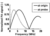
- pulse width t LP 77 ns (nanoseconds) of the laser light L
- FIG. 2 which is a graph showing the spectrum of the photoacoustic wave
- the center frequency of the photoacoustic wave immediately before 11 changes from 6.5 MHz (megahertz) to a lower center frequency.
- the reception frequency band of the probe 11 is a band having a width of 70% to 100% with respect to the center frequency
- the frequency of acoustic waves that can be received by the probe 11 with a center frequency of 6.5 MHz (megahertz) is 3.. It is considered to be about 2 to 9.8 MHz (megahertz). Therefore, in the present embodiment, in consideration of attenuation in the subject M, the center frequency of the photoacoustic wave immediately before the probe 11 is a frequency that can be received by the probe 11 having a center frequency of 6.5 MHz (megahertz).
- the excitation light generation conditions are adjusted so as to include a large number of signals of a component of 3.2 to 9.8 MHz (megahertz).
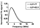
- FIG. 3 which is a graph showing the spectrum of the photoacoustic wave
- the pulse width t LP of the laser light L is set to 62.5 ns (nanoseconds)
- the pulse width t LP of the laser light L is 77 ns
- the frequency of acoustic waves that can be received by the probe 11 with a center frequency of 6.5 MHz (megahertz) can include many signals of components of 3.2 to 9.8 MHz (megahertz) .
- the receiving efficiency of the photoacoustic wave in the probe 11 can be raised.
- the excitation light is such that the center frequency of the sensitivity of the probe 11 and the center frequency of the photoacoustic wave generated in the subject M become close.
- how much the pulse width of the laser light L should be shortened may be adjusted based on the attenuation characteristics of the photoacoustic wave in the subject M, and more specifically, the photoacoustic wave in the subject M
- the pulse width of the laser beam L may be made shorter as the attenuation of the laser beam L increases (the depth of the observation target in the above example increases).
- a plurality for example, main observation targets for each type of the probe 11 as a table in the ultrasonic unit 12 in advance. It is desirable to be stored for shallow location, intermediate location, deep location, etc.) so that the user can select them.
- the excitation light generation condition is automatically switched according to the photoacoustic image or the image depth (maximum depth in the image) or the focal depth (depth of the observation object) of the ultrasonic image to be synthesized with the photoacoustic image. You may do so.
- the excitation light generation condition may be automatically switched according to the type of tissue of the subject M.
- the number of pulses of the laser light L is not limited to one, and may be two or more.
- the photoacoustic image generation unit 24 to correct the object position in the photoacoustic image according to the excitation light generation condition.
- the center frequency of the photoacoustic wave immediately before the probe 11 and the center frequency in the sensitivity of the probe 11 do not necessarily have to coincide with each other.
- the center frequency of the photoacoustic wave may be set at an arbitrary position in the frequency band in the sensitivity of the probe 11 from the requirement of the image quality and the like.
- the photoacoustic measuring device of the present invention is not limited only to the above-mentioned embodiment, and various corrections and changes from the composition of the above-mentioned embodiment Those applied are also included in the scope of the present invention.
Landscapes
- Life Sciences & Earth Sciences (AREA)
- Health & Medical Sciences (AREA)
- Biomedical Technology (AREA)
- Biophysics (AREA)
- Nuclear Medicine, Radiotherapy & Molecular Imaging (AREA)
- Pathology (AREA)
- Radiology & Medical Imaging (AREA)
- Engineering & Computer Science (AREA)
- Physics & Mathematics (AREA)
- Heart & Thoracic Surgery (AREA)
- Medical Informatics (AREA)
- Molecular Biology (AREA)
- Surgery (AREA)
- Animal Behavior & Ethology (AREA)
- General Health & Medical Sciences (AREA)
- Public Health (AREA)
- Veterinary Medicine (AREA)
- Investigating Or Analyzing Materials By The Use Of Ultrasonic Waves (AREA)
- Ultra Sonic Daignosis Equipment (AREA)
Abstract
L'invention concerne un dispositif de génération d'images photoacoustiques dans lequel la profondeur visible dans une image photoacoustique est améliorée, et un procédé d'acquisition d'images pour un dispositif de génération d'images photoacoustiques. Une unité de commande (30) d'un dispositif de génération d'images photoacoustiques effectue une commande pour ajuster, dans une source de lumière, une condition de génération de lumière d'excitation sur la base de la largeur d'impulsion de la lumière d'excitation générée dans la source de lumière, sur la base d'une caractéristique de fréquence de réception d'un moyen de détection d'ondes acoustiques et d'une caractéristique d'atténuation d'une onde photoacoustique chez un sujet.
Applications Claiming Priority (2)
| Application Number | Priority Date | Filing Date | Title |
|---|---|---|---|
| JP2017-164588 | 2017-08-29 | ||
| JP2017164588 | 2017-08-29 |
Publications (1)
| Publication Number | Publication Date |
|---|---|
| WO2019044594A1 true WO2019044594A1 (fr) | 2019-03-07 |
Family
ID=65525345
Family Applications (1)
| Application Number | Title | Priority Date | Filing Date |
|---|---|---|---|
| PCT/JP2018/030838 Ceased WO2019044594A1 (fr) | 2017-08-29 | 2018-08-21 | Dispositif de génération d'images photoacoustiques et procédé d'acquisition d'images |
Country Status (1)
| Country | Link |
|---|---|
| WO (1) | WO2019044594A1 (fr) |
Cited By (2)
| Publication number | Priority date | Publication date | Assignee | Title |
|---|---|---|---|---|
| WO2021048951A1 (fr) * | 2019-09-11 | 2021-03-18 | 日本電信電話株式会社 | Sonde photo-acoustique |
| JP2022053367A (ja) * | 2020-09-24 | 2022-04-05 | 株式会社Jvcケンウッド | コミュニケーション装置、コミュニケーション方法、及びコンピュータプログラム |
Citations (3)
| Publication number | Priority date | Publication date | Assignee | Title |
|---|---|---|---|---|
| JP2016047232A (ja) * | 2014-08-27 | 2016-04-07 | プレキシオン株式会社 | 光音響画像化装置 |
| JP2016047077A (ja) * | 2014-08-27 | 2016-04-07 | プレキシオン株式会社 | 光音響画像化装置 |
| JP2017035407A (ja) * | 2015-08-14 | 2017-02-16 | セイコーエプソン株式会社 | 光音響センサー及び電子機器 |
-
2018
- 2018-08-21 WO PCT/JP2018/030838 patent/WO2019044594A1/fr not_active Ceased
Patent Citations (3)
| Publication number | Priority date | Publication date | Assignee | Title |
|---|---|---|---|---|
| JP2016047232A (ja) * | 2014-08-27 | 2016-04-07 | プレキシオン株式会社 | 光音響画像化装置 |
| JP2016047077A (ja) * | 2014-08-27 | 2016-04-07 | プレキシオン株式会社 | 光音響画像化装置 |
| JP2017035407A (ja) * | 2015-08-14 | 2017-02-16 | セイコーエプソン株式会社 | 光音響センサー及び電子機器 |
Cited By (3)
| Publication number | Priority date | Publication date | Assignee | Title |
|---|---|---|---|---|
| WO2021048951A1 (fr) * | 2019-09-11 | 2021-03-18 | 日本電信電話株式会社 | Sonde photo-acoustique |
| JP2022053367A (ja) * | 2020-09-24 | 2022-04-05 | 株式会社Jvcケンウッド | コミュニケーション装置、コミュニケーション方法、及びコンピュータプログラム |
| JP7574589B2 (ja) | 2020-09-24 | 2024-10-29 | 株式会社Jvcケンウッド | コミュニケーション装置、コミュニケーション方法、及びコンピュータプログラム |
Similar Documents
| Publication | Publication Date | Title |
|---|---|---|
| JP5275830B2 (ja) | 光超音波断層画像化装置および光超音波断層画像化方法 | |
| US10098547B2 (en) | Photoacoustic measurement device, photoacoustic measurement method, and probe contact determination method | |
| JPWO2011052061A1 (ja) | 光音響装置 | |
| JP5840070B2 (ja) | 光音響計測装置および光音響計測装置用プローブ | |
| US11986344B2 (en) | Portable probe for photoacoustic tomography and real-time photoacoustic tomography device | |
| JP6049215B2 (ja) | 光音響計測装置並びにそれに利用される信号処理装置および信号処理方法 | |
| JP2010125260A (ja) | 生体検査装置 | |
| WO2012077356A1 (fr) | Sonde pour inspection photo-acoustique, et dispositif d'inspection photo-acoustique | |
| JP2013056032A (ja) | 被検体情報取得装置および被検体情報取得方法 | |
| JP2016101393A (ja) | 被検体情報取得装置およびその制御方法 | |
| CN104856728A (zh) | 光声装置 | |
| WO2019044594A1 (fr) | Dispositif de génération d'images photoacoustiques et procédé d'acquisition d'images | |
| US11119199B2 (en) | Acoustic wave image generation apparatus and acoustic wave image generation method | |
| JP2015126900A (ja) | 光音響装置 | |
| US11399719B2 (en) | Probe for photoacoustic measurement and photoacoustic measurement apparatus including same | |
| US20170296063A1 (en) | Photoacoustic measurement probe and probe unit and photoacoustic measurement apparatus including the same | |
| US20200187784A1 (en) | Photoacoustic image generation apparatus and image acquisition method | |
| WO2017135167A1 (fr) | Système, dispositif et procédé de génération d'image photoacoustique | |
| JP2014184025A (ja) | 光音響計測装置、プローブおよび音響整合部材並びに光音響計測方法およびプローブの接触判断方法 | |
| JP5868458B2 (ja) | 測定装置 | |
| WO2018235781A1 (fr) | Dispositif de génération d'images d'ondes acoustiques et procédé d'analyse d'images opto-acoustiques | |
| JP2018111050A (ja) | 光音響装置 | |
| WO2019044212A1 (fr) | Dispositif de génération d'images photoacoustiques et procédé d'acquisition d'images | |
| JP2017035589A (ja) | 光音響装置 | |
| JP2017192841A (ja) | 生体検査装置 |
Legal Events
| Date | Code | Title | Description |
|---|---|---|---|
| 121 | Ep: the epo has been informed by wipo that ep was designated in this application |
Ref document number: 18849548 Country of ref document: EP Kind code of ref document: A1 |
|
| NENP | Non-entry into the national phase |
Ref country code: DE |
|
| 122 | Ep: pct application non-entry in european phase |
Ref document number: 18849548 Country of ref document: EP Kind code of ref document: A1 |
|
| NENP | Non-entry into the national phase |
Ref country code: JP |