WO2019044934A1 - Système optique d'imagerie à foyer unique , unité de lentilles et dispositif d'imagerie - Google Patents
Système optique d'imagerie à foyer unique , unité de lentilles et dispositif d'imagerie Download PDFInfo
- Publication number
- WO2019044934A1 WO2019044934A1 PCT/JP2018/032035 JP2018032035W WO2019044934A1 WO 2019044934 A1 WO2019044934 A1 WO 2019044934A1 JP 2018032035 W JP2018032035 W JP 2018032035W WO 2019044934 A1 WO2019044934 A1 WO 2019044934A1
- Authority
- WO
- WIPO (PCT)
- Prior art keywords
- lens
- optical system
- imaging optical
- focus imaging
- single focus
- Prior art date
- Legal status (The legal status is an assumption and is not a legal conclusion. Google has not performed a legal analysis and makes no representation as to the accuracy of the status listed.)
- Ceased
Links
Images



Classifications
-
- G—PHYSICS
- G02—OPTICS
- G02B—OPTICAL ELEMENTS, SYSTEMS OR APPARATUS
- G02B13/00—Optical objectives specially designed for the purposes specified below
- G02B13/04—Reversed telephoto objectives
-
- G—PHYSICS
- G02—OPTICS
- G02B—OPTICAL ELEMENTS, SYSTEMS OR APPARATUS
- G02B13/00—Optical objectives specially designed for the purposes specified below
- G02B13/18—Optical objectives specially designed for the purposes specified below with lenses having one or more non-spherical faces, e.g. for reducing geometrical aberration
Definitions
- the present invention relates to a wide-angle single-focus imaging optical system, a lens unit, and an imaging apparatus, and more particularly to a single-focus imaging optical system having an angle of view of 180 ° or more.
- the present invention has been made in view of the above background art, and an object of the present invention is to provide a single-focus imaging optical system having a small size and high optical performance while having a wide angle of view.
- Another object of the present invention is to provide a lens unit and an imaging apparatus provided with the single focus imaging optical system.
- the single-focus imaging optical system reflecting one aspect of the present invention includes, in order from the object side, a first lens having negative refractive power, and a first lens having a biconcave shape. 2 lens, a biconvex third lens, an aperture stop, a fourth lens having a positive refractive power, a negative fifth lens having a convex object side surface in the near-axis region, and a positive refractive power It substantially consists of the sixth lens.
- a lens unit reflecting one aspect of the present invention includes the above-described single focus imaging optical system and a lens barrel that holds the single focus imaging optical system.
- an imaging apparatus reflecting one aspect of the present invention includes the above-described single focus imaging optical system, and an imaging element for detecting an image obtained from the single focus imaging optical system. Equipped with
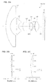
- FIG. 2A is a cross-sectional view of the single-focus imaging optical system of Example 1.
- FIGS. 2B and 2C are longitudinal aberration diagrams of Example 1.
- FIG. 3A is a cross-sectional view of the single focus imaging optical system of Example 2
- FIGS. 3B and 3C are longitudinal aberration diagrams of Example 2.
- FIG. 4A is a cross-sectional view of the single focus imaging optical system of Example 3
- FIGS. 4B and 4C are longitudinal aberration diagrams of Example 3.
- FIG. FIG. 5A is a cross-sectional view of the single focus imaging optical system of Example 4, and FIGS. 5B and 5C are longitudinal aberration diagrams of Example 4.
- FIG. 6A is a cross-sectional view of the single-focus imaging optical system of Example 5, and FIGS. 6B and 6C are longitudinal aberration diagrams of Example 5.
- FIG. 7A is a cross-sectional view of the single-focus imaging optical system of Example 6, and FIGS. 7B and 7C are longitudinal aberration diagrams of Example 6.
- FIG. 8A is a cross-sectional view of the single focus imaging optical system of Example 7, and FIGS. 8B and 8C are longitudinal aberration diagrams of Example 7.
- FIG. 9A is a cross-sectional view of the single focus imaging optical system of Example 8, and FIGS. 9B and 9C are longitudinal aberration diagrams of Example 8.
- FIG. 10A is a cross-sectional view of the single-focus imaging optical system of Example 9, and FIGS. 10B and 10C are longitudinal aberration diagrams of Example 9.
- FIG. 10A is a cross-sectional view of the single-focus imaging optical system of Example 9 and FIGS. 10B and 10C are longitudinal aberration diagrams of Example 9.
- FIG. 1 is a view showing an imaging device 100 according to an embodiment of the present invention.
- the imaging device 100 includes a camera module 30 for forming an image signal, and a processing unit 60 that causes the camera module 30 to operate to exhibit a function as the imaging device 100.
- the camera module 30 includes a lens unit 40 having a single focus imaging optical system 10 therein, and a sensor unit 50 for converting an object image formed by the single focus imaging optical system 10 into an image signal.
- the camera module 30 incorporates the single focus imaging optical system 10 described in detail below, and a wide angle of view can be secured, and the imaging device 100 having a small size and high optical performance can be provided.
- the lens unit 40 includes a single focus imaging optical system 10 which is a wide-angle optical system, and a lens barrel 41 to which the single focus imaging optical system 10 is assembled.
- the single-focus imaging optical system 10 includes first to sixth lenses L1 to L6, which will be described in detail later, and the first to third lenses L1 to L3 forming the front group on the object side with the diaphragm ST interposed therebetween. And the fourth to sixth lenses L4 to L6 constituting the rear group on the image side.
- the lens barrel 41 is formed of metal, resin, a mixture of resin and glass fiber, or the like, and the single focus imaging optical system 10 is housed and held inside.
- the lens barrel 41 is formed of a mixture of metal and resin with glass fiber, the lens barrel 41 is less likely to expand than the resin, and the single focus imaging optical system 10 can be stably fixed.
- the lens barrel 41 has an opening OP1 through which a ray bundle from the object side is made incident.
- the first to sixth lenses L1 to L6 constituting the single-focus imaging optical system 10 are held directly or indirectly on the inner surface side of the lens barrel 41 at their flange portions or outer peripheral portions, and in the optical axis AX direction And the position perpendicular to the optical axis AX.
- the sensor unit 50 includes a solid-state imaging device 51 that photoelectrically converts an object image formed by the single-focus imaging optical system 10, a substrate 52 supporting the solid-state imaging device 51 from behind and provided with wiring, peripheral circuits, and the like. And a sensor holder 53 for holding the solid-state imaging device 51 via the substrate 52.
- the solid-state imaging device 51 is, for example, a CMOS type image sensor.
- the substrate 52 includes wires for operating the solid-state imaging device 51, peripheral circuits, and the like.
- the sensor holder 53 is formed of a resin or other material, and supports the parallel flat plate F so as to face the solid-state image sensor 51 as well as positioning the solid-state image sensor 51 with respect to the optical axis AX.
- the lens barrel 41 of the lens unit 40 is fixed in a state of being positioned so as to be fitted to the sensor holder 53.
- the solid-state imaging device (imaging device) 51 includes a photoelectric conversion unit 51a having an imaging surface I, and a signal processing circuit (not shown) is formed around the photoelectric conversion unit 51a.
- the solid-state imaging device 51 is not limited to the above-described CMOS-type image sensor, and may be one to which a CCD or the like is applied.
- the parallel flat plate F disposed between the single focus imaging optical system 10 and the solid state imaging device 51 is an optical low pass filter, a seal glass of the solid state imaging device, an IR cut filter, a wavelength selection filter, or the like.
- the processing unit 60 includes a drive unit 61, an input unit 62, a storage unit 63, a display unit 64, and a control unit 68.
- the drive unit 61 operates the solid-state imaging device 51 by receiving supply of a digital control signal or the like from the control unit 68.
- the drive unit 61 receives YUV and other digital pixel signals as image data from the solid-state imaging device 51 and transfers the digital pixel signals to the control unit 68.
- the input unit 62 is a unit for receiving a user's operation or a command from an external device
- the storage unit 63 is a unit for storing information necessary for the operation of the imaging device 100, image data acquired by the camera module 30, etc.
- the display unit 64 is a portion that displays information to be presented to the user, a photographed image, and the like.
- the control unit 68 integrally controls the operations of the drive unit 61, the input unit 62, the storage unit 63, and the like, and can perform various image processing on image data obtained by the camera module 30, for example. Such image data can be output to an external circuit.
- the details of the single-focus imaging optical system 10 according to the embodiment will be described below with reference to FIG.
- the single-focus imaging optical system 10 illustrated in FIG. 1 has the same configuration as the single-focus imaging optical system 10A of Example 1 described later.
- the illustrated single-focus imaging optical system 10 is a wide-angle lens for forming an object image on the imaging surface I of the solid-state imaging device 51, and is a first lens L1 having negative refractive power in order from the object side.
- the first lens L1 is a spherical type lens formed of glass and composed of a spherical surface
- the fourth lens L4 is an aspheric type lens formed of glass and composed of an aspheric surface.
- the second, third, fifth and sixth lenses L2, L3, L5 and L6 are respectively made of plastic and have at least one aspheric shape.
- the single-focus imaging optical system 10 is a wide-angle lens having an angle of view of 180 ° or more, and can be reduced in the diameter of the front lens by adopting a retrofocus type preceded by a negative lens. A back focus sufficient to install sealing glass or the like of the imaging element 51 can be secured.
- the negative lens into a two-lens configuration of the first and second lenses L1 and L2, it is possible to divide negative power and to improve the performance and reduce the error sensitivity more than when one negative lens is provided. .
- the third lens L3 biconvex shape a sufficient positive power is secured, and in the lens group before the stop ST, the aberration generated in the negative lens of the first lens L1 and the second lens L2 is cancelled.
- the fourth lens L4, the fifth lens L5, and the sixth lens L6 are arranged to be a positive / negative positive power arrangement, so-called triplets can be obtained, and aberration correction in the lens group behind the aperture stop ST becomes good. Furthermore, if the object side surface S51 of the fifth lens L5 is a convex surface in the paraxial region, the principal point interval between the fourth lens L4 and the fifth lens L5 increases, and the fourth and fifth lenses L4 and L5 have the same power. However, since the combined power of the fourth lens L4 and the fifth lens L5 can be made stronger than when the principal point interval is narrow, aberration and error sensitivity generated in each of the fourth and fifth lenses L4 and L5 are suppressed.
- the single-focus imaging optical system 10 can be miniaturized.
- the fourth and fifth lenses L4 and L5, the fifth and sixth lenses L5 and L6, and the like may be cemented to each other in order to suppress chromatic aberration, spherical aberration, and error sensitivity.
- the single-focus imaging optical system 10 satisfies the following conditional expression (1). 0.1 ⁇ (d34 / f) / (tan (w / 2)) ⁇ 0.8 (1)
- the value d34 is the distance between the third lens L3 and the fourth lens L4
- the value f is the focal length of the entire system
- the value w is the maximum half angle of view.
- the single-focus imaging optical system 10 satisfies the following conditional expression (2). -3 ⁇ f2 / f ⁇ -1 (2)
- the value f2 is the focal length of the second lens L2.
- the refractive power of the second lens L2 does not become too strong, and the performance variation due to the astigmatism and the manufacturing error generated here can be suppressed. it can.
- the value f2 / f of the conditional expression (2) is set below the upper limit or more, the refractive power of the second lens L2 does not become too weak, and the optical system can be kept compact.
- the single focus imaging optical system 10 satisfies the following conditional expression (3). 3 ⁇ f3 / f ⁇ 6 (3)
- the value f3 is the focal length of the third lens L3.
- the refractive power of the third lens L3 does not become too strong, and the performance variation due to the spherical aberration and coma aberration generated here and the manufacturing error is suppressed. be able to.
- the refractive power of the third lens L3 does not become too weak, and the optical system can be kept compact.
- the single focus imaging optical system 10 satisfies the following conditional expression (4). -3 ⁇ f5 / f ⁇ -1 (4)
- the value f5 is the focal length of the fifth lens.
- the refractive power of the fifth lens L5 does not become too strong, and suppressing the performance variation due to the astigmatism and the manufacturing error generated here. it can.
- the refractive power of the fifth lens L5 does not become too weak, and the optical system can be kept compact.
- the single focus imaging optical system 10 satisfies the following conditional expression (5). 2 ⁇ f1 / f2 ⁇ 5.5 (5)
- the refractive power of the first lens L1 does not become too strong relative to the second lens L2, and the burden on the first lens L1 can be relatively reduced. Astigmatism and error sensitivity generated in the first lens L1 can be suppressed.
- the refractive power of the second lens L2 does not become too strong relative to the first lens L1, and the load on the second lens L2 is relatively reduced. As a result, it is possible to suppress astigmatism and error sensitivity generated in the second lens L2.
- the single focus imaging optical system 10 satisfies the following conditional expression (6). ⁇ 8 ⁇ f1 / f ⁇ ⁇ 5 (6)
- the refractive power of the first lens L1 does not become too strong, and the performance variation due to the astigmatism and the manufacturing error generated here can be suppressed. it can.
- the refractive power of the first lens L1 does not become too weak and the diameter of the front lens does not become too large. can do.
- the single focus imaging optical system 10 satisfies the following conditional expression (7). 1.5 ⁇ f4 / f ⁇ 3 (7)
- the value f4 is the focal length of the fourth lens L4.
- the refractive power of the fourth lens L4 does not become too strong, and the performance variation due to the spherical aberration and coma aberration generated here and the manufacturing error is suppressed. be able to.
- the refractive power of the fourth lens L4 does not become too weak, and the optical system can be kept compact.
- the single-focus imaging optical system 10 satisfies the following conditional expression (8). ⁇ 0.4 ⁇ f ⁇ ⁇ (1 / fplk) ⁇ ⁇ 0.2 (8)
- the value fplk is the focal length of the k-th plastic lens from the object side.
- the distance from the lens to the focal point does not become too short when changing, and the distance from the lens to the focal point does not become too long when the temperature changes to the low temperature side.
- the value f ⁇ ⁇ (1 / fplk) in the conditional expression (8) is set to the upper limit or less, the sum of the focal lengths of the plastic lenses does not become too small to the negative value side.
- the distance from the lens to the focal point does not become too long when changed, and the distance from the lens to the focal point does not become too short when the temperature changes to the low temperature side.
- plasticizing the lenses L2, L3, L5, and L6 reduces the weight of the optical system, and adds an aspheric surface by injection molding or the like to increase the shape freedom more than at a spherical surface, and correct aberrations well.
- the single focus imaging optical system 10 satisfies the following conditional expression (9).
- the value LL4 is the Abbe number of the fourth lens L4.
- the single focus imaging optical system 10 satisfies the following conditional expression (10). 1.8 ⁇ nL1 (10)
- the value nL1 is the refractive index of the first lens L1.
- the radius of curvature can be relaxed even if the first lens L1 has the same power, and astigmatism and the like generated on this surface can be reduced. Further, even if the power of the first lens L1 is increased to reduce the diameter of the front lens, aberrations are relatively unlikely to occur, and both downsizing and high performance of the optical system can be achieved.
- the single-focus imaging optical system 10 may further include another optical element (for example, a lens, a filter member, and the like) that does not substantially have a refractive power.
- another optical element for example, a lens, a filter member, and the like
- the single focus imaging optical system 10 of the present embodiment is premised to be used for a fixed focus camera module 30 or an imaging apparatus 100 having no focus function. That is, the lens barrel 41 is not provided with the movable mechanism of the lens.
- the parallel flat plate F is not essential.
- the filter for wavelength selection not have a separately disposed structure but its function be imparted to the lens.
- infrared cut coating may be performed on the surface of one or more lenses.
- security cameras such as surveillance cameras, door phone cameras, authentication cameras or lenses for marketing cameras, lenses for in-vehicle cameras mounted on automobiles or other moving objects
- medical Examples include endoscopes, healthcare measurements, industrial endoscopes and other medical or industrial optical lenses.
- the single-focus imaging optical system 10 or the imaging apparatus 100 may be applied to applications other than these where wide angle is required.
- the surface described with “*” after each surface number is a surface having an aspheric shape, and the shape of the aspheric surface has the vertex of the surface as the origin and the X axis in the optical axis direction.
- the height in the direction perpendicular to the optical axis is denoted by h in the following "Equation 1".
- Ai i-th order aspheric coefficient
- R radius of curvature
- K conical constant
- Example 1 The entire specifications of the single-focus imaging optical system of Example 1 are shown in Table 1 below. [Table 1] f (mm) 1.28 Fno 2.0 w (°) 110.0 ymax (mm) 2.64 TL (mm) 17.28 BF (mm) 2.41
- the data of the lens surface of the single focus imaging optical system of Example 1 is shown in Table 2 below.
- the surface number is represented by “Surf. N”
- the aperture stop is represented by “ST”
- infinity is represented by “INF”.
- Image represents the imaging plane I of the imaging device (or the imaging plane of the single focus imaging optical system).
- the aspherical coefficients of the lens surface of the single focus imaging optical system of Example 1 are shown in Table 3 below. In the following it (including lens data in Tables), and represents an exponent of 10 (for example, 2.5 ⁇ 10 -02) with E (e.g. 2.5E-02).
- FIG. 2A is a cross-sectional view of the single-focus imaging optical system 10A of Example 1 and the like.
- the single-focus imaging optical system 10A includes, in order from the object side, the negative first lens L1, the negative second lens L2, the positive third lens L3, the stop (or aperture stop) ST, and the positive third It consists essentially of a four lens L4, a negative fifth lens L5, and a positive sixth lens L6.
- the first and fourth lenses L1 and L4 are made of glass
- the second, third, fifth and sixth lenses L2, L3, L5 and L6 are made of plastic.
- a parallel plate (filter) F of an appropriate thickness is disposed between the sixth lens L6 and the solid-state imaging device 51.
- the parallel flat plate (filter) F is a parallel flat plate on which an optical low pass filter, an IR cut filter, a seal glass of the solid-state imaging device 51, and the like are assumed.
- Reference symbol I indicates an imaging surface which is a projection surface of the solid-state imaging device 51.
- symbol F and I it is the same also in the subsequent Example.
- FIGS. 2B and 2C show longitudinal aberration diagrams (spherical aberration and astigmatism) of the single-focus imaging optical system 10A of Example 1.
- a solid line represents a sagittal image plane, and a dotted line represents a meridional image plane.
- the amount of focus movement (normal temperature) of the plastic lens (specifically, the second, third, fifth, and sixth lenses L2, L3, L5, L6) due to temperature change
- the movement amount when changing from (25 ° C.) to 105 ° C. is ⁇ 0.012 mm.
- Example 2 Table 4 below shows the overall specifications of the single-focus imaging optical system of Example 2. [Table 4] f (mm) 1.29 Fno 2.0 w (°) 110.0 ymax (mm) 2.63 TL (mm) 17.08 BF (mm) 2.41
- FIG. 3A is a cross-sectional view of the single-focus imaging optical system 10B and the like of the second embodiment.
- the single-focus imaging optical system 10B includes, in order from the object side, a negative first lens L1, a negative second lens L2, a positive third lens L3, a stop (or an aperture stop) ST, and a positive third It consists essentially of a four lens L4, a negative fifth lens L5, and a positive sixth lens L6.
- the first and fourth lenses L1 and L4 are made of glass
- the second, third, fifth and sixth lenses L2, L3, L5 and L6 are made of plastic.
- a parallel flat plate F of an appropriate thickness is disposed between the sixth lens L6 and the solid-state imaging device 51.
- FIGS. 3B and 3C show longitudinal aberration diagrams (spherical aberration and astigmatism) of the single-focus imaging optical system 10B of Example 2.
- FIG. 3A shows longitudinal aberration diagrams (spherical aberration and astigmatism) of the single-focus imaging optical system 10B of Example 2.
- the amount of focus movement (normal temperature) of the plastic lens (specifically, the second, third, fifth, and sixth lenses L2, L3, L5, L6) due to temperature change
- the movement amount when changing from (25 ° C.) to 105 ° C. is ⁇ 0.012 mm.
- Table 7 shows the overall specifications of the single-focus imaging optical system of Example 3. [Table 7] f (mm) 1.29 Fno 2.0 w (°) 110.0 ymax (mm) 2.64 TL (mm) 16.86 BF (mm) 2.30
- FIG. 4A is a cross-sectional view of the single-focus imaging optical system 10C of Example 3 and the like.
- the single-focus imaging optical system 10C includes, in order from the object side, a negative first lens L1, a negative second lens L2, a positive third lens L3, a stop (or an aperture stop) ST, and a positive third It consists essentially of a four lens L4, a negative fifth lens L5, and a positive sixth lens L6.
- the first and fourth lenses L1 and L4 are made of glass
- the second, third, fifth and sixth lenses L2, L3, L5 and L6 are made of plastic.
- a parallel flat plate F of an appropriate thickness is disposed between the sixth lens L6 and the solid-state imaging device 51.
- FIGS. 4B and 4C show longitudinal aberration diagrams (spherical aberration and astigmatism) of the single-focus imaging optical system 10C of Example 3.
- FIG. 4B and 4C show longitudinal aberration diagrams (spherical aberration and astigmatism) of the single-focus imaging optical system 10C of Example 3.
- the amount of focus movement (normal temperature) due to the temperature change of the plastic lenses (specifically, the second, third, fifth, and sixth lenses L2, L3, L5, L6)
- the movement amount when changing from (25 ° C.) to 105 ° C. is ⁇ 0.012 mm.
- Example 4 The entire specifications of the single-focus imaging optical system of Example 4 are shown in Table 10 below. [Table 10] f (mm) 1.29 Fno 2.0 w (°) 110.0 ymax (mm) 2.64 TL (mm) 16.83 BF (mm) 2.26
- FIG. 5A is a cross-sectional view of the single focus imaging optical system 10D and the like of the fourth embodiment.
- the single-focus imaging optical system 10D includes, in order from the object side, a negative first lens L1, a negative second lens L2, a positive third lens L3, a stop (or an aperture stop) ST, and a positive third It consists essentially of a four lens L4, a negative fifth lens L5, and a positive sixth lens L6.
- the first and fourth lenses L1 and L4 are made of glass
- the second, third, fifth and sixth lenses L2, L3, L5 and L6 are made of plastic.
- a parallel flat plate F of an appropriate thickness is disposed between the sixth lens L6 and the solid-state imaging device 51.
- FIG. 5B and 5C show longitudinal aberration diagrams (spherical aberration and astigmatism) of the single-focus imaging optical system 10D of Example 4.
- FIG. 5B and 5C show longitudinal aberration diagrams (spherical aberration and astigmatism) of the single-focus imaging optical system 10D of Example 4.
- the amount of focus movement (normal temperature) of the plastic lens (specifically, the second, third, fifth, and sixth lenses L2, L3, L5, L6) due to temperature change
- the movement amount when changing from (25 ° C.) to 105 ° C. is ⁇ 0.012 mm.
- Example 5 The entire specifications of the single-focus imaging optical system of Example 5 are shown in Table 13 below. [Table 13] f (mm) 1.36 Fno 2.0 w (°) 110.0 ymax (mm) 2.64 TL (mm) 19.93 BF (mm) 2.59
- FIG. 6A is a cross-sectional view of the single-focus imaging optical system 10E and the like of the fifth embodiment.
- the single-focus imaging optical system 10E includes, in order from the object side, a negative first lens L1, a negative second lens L2, a positive third lens L3, a stop (or an aperture stop) ST, and a positive third It consists essentially of a four lens L4, a negative fifth lens L5, and a positive sixth lens L6.
- the first and fourth lenses L1 and L4 are made of glass
- the second, third, fifth and sixth lenses L2, L3, L5 and L6 are made of plastic.
- a parallel flat plate F of an appropriate thickness is disposed between the sixth lens L6 and the solid-state imaging device 51.
- FIG. 6B and 6C show longitudinal aberration diagrams (spherical aberration and astigmatism) of the single-focus imaging optical system 10E of Example 5.
- FIG. 6B and 6C show longitudinal aberration diagrams (spherical aberration and astigmatism) of the single-focus imaging optical system 10E of Example 5.
- the amount of focus movement (normal temperature) of the plastic lens (specifically, the second, third, fifth, and sixth lenses L2, L3, L5, L6) due to temperature change
- the movement amount when changing from (25 ° C.) to 105 ° C. is 0.009 mm.
- Example 6 The entire specifications of the single-focus imaging optical system of Example 6 are shown in Table 16 below. [Table 16] f (mm) 1.27 Fno 2.0 w (°) 110.0 ymax (mm) 2.64 TL (mm) 16.00 BF (mm) 2.07
- FIG. 7A is a cross-sectional view of the single-focus imaging optical system 10F and the like of the sixth embodiment.
- the single-focus imaging optical system 10F includes, in order from the object side, a negative first lens L1, a negative second lens L2, a positive third lens L3, a stop (or an aperture stop) ST, and a positive third It consists essentially of a four lens L4, a negative fifth lens L5, and a positive sixth lens L6.
- the first and fourth lenses L1 and L4 are made of glass
- the second, third, fifth and sixth lenses L2, L3, L5 and L6 are made of plastic.
- a parallel flat plate F of an appropriate thickness is disposed between the sixth lens L6 and the solid-state imaging device 51.
- FIGS. 7B and 7C show longitudinal aberration diagrams (spherical aberration and astigmatism) of the single-focus imaging optical system 10F of Example 6.
- FIG. 7B and 7C show longitudinal aberration diagrams (spherical aberration and astigmatism) of the single-focus imaging optical system 10F of Example 6.
- the amount of focus movement (normal temperature) of the plastic lenses (specifically, the second, third, fifth, and sixth lenses L2, L3, L5, L6) due to temperature change
- the movement amount when changing from (25 ° C.) to 105 ° C. is ⁇ 0.009 mm.
- Example 7 Table 19 below shows the overall specifications of the single-focus imaging optical system of Example 7. [Table 19] f (mm) 1.07 Fno 2.0 w (°) 110.0 ymax (mm) 2.64 TL (mm) 16.13 BF (mm) 2.06
- FIG. 8A is a cross-sectional view of a single focus imaging optical system 10G and the like according to a seventh example.
- the single-focus imaging optical system 10G includes, in order from the object side, a negative first lens L1, a negative second lens L2, a positive third lens L3, a stop (or an aperture stop) ST, and a positive third It consists essentially of a four lens L4, a negative fifth lens L5, and a positive sixth lens L6.
- the first and fourth lenses L1 and L4 are made of glass
- the second, third, fifth and sixth lenses L2, L3, L5 and L6 are made of plastic.
- a parallel flat plate F of an appropriate thickness is disposed between the sixth lens L6 and the solid-state imaging device 51.
- FIG. 8B and 8C show longitudinal aberration diagrams (spherical aberration and astigmatism) of the single-focus imaging optical system 10G of Example 7.
- FIG. 8B and 8C show longitudinal aberration diagrams (spherical aberration and astigmatism) of the single-focus imaging optical system 10G of Example 7.
- the amount of focus movement (normal temperature) of the plastic lenses (specifically, the second, third, fifth, and sixth lenses L2, L3, L5, L6) due to the temperature change
- the movement amount when changing from (25 ° C.) to 105 ° C. is ⁇ 0.009 mm.
- Example 8 Table 22 below shows the overall specifications of the single-focus imaging optical system of Example 8. [Table 22] f (mm) 1.24 Fno 2.0 w (°) 110.0 ymax (mm) 2.65 TL (mm) 16.56 BF (mm) 2.13
- FIG. 9A is a cross-sectional view of a single focus imaging optical system 10H and the like according to an eighth embodiment.
- the single-focus imaging optical system 10H includes, in order from the object side, a negative first lens L1, a negative second lens L2, a positive third lens L3, a stop (or an aperture stop) ST, and a positive third It consists essentially of a four lens L4, a negative fifth lens L5, and a positive sixth lens L6.
- the first and fourth lenses L1 and L4 are made of glass
- the second, third, fifth and sixth lenses L2, L3, L5 and L6 are made of plastic.
- a parallel flat plate F of an appropriate thickness is disposed between the sixth lens L6 and the solid-state imaging device 51.
- FIG. 9B and 9C show longitudinal aberration diagrams (spherical aberration and astigmatism) of the single-focus imaging optical system 10H of Example 8.
- FIG. 9B and 9C show longitudinal aberration diagrams (spherical aberration and astigmatism) of the single-focus imaging optical system 10H of Example 8.
- the amount of focus movement (normal temperature) of the plastic lenses (specifically, the second, third, fifth, and sixth lenses L2, L3, L5, L6) due to the temperature change
- the movement amount when changing from (25 ° C.) to 105 ° C. is ⁇ 0.010 mm.
- Table 25 below shows the overall specifications of the single-focus imaging optical system of Example 9. [Table 25] f (mm) 1.33 Fno 2.0 w (°) 110.0 ymax (mm) 2.65 TL (mm) 15.98 BF (mm) 2.16
- FIG. 10A is a cross-sectional view of a single focus imaging optical system 10I and the like according to a ninth example.
- the single-focus imaging optical system 10I includes, in order from the object side, a negative first lens L1, a negative second lens L2, a positive third lens L3, a stop (or an aperture stop) ST, and a positive third It consists essentially of a four lens L4, a negative fifth lens L5, and a positive sixth lens L6.
- the first and fourth lenses L1 and L4 are made of glass
- the second, third, fifth and sixth lenses L2, L3, L5 and L6 are made of plastic.
- a parallel flat plate F of an appropriate thickness is disposed between the sixth lens L6 and the solid-state imaging device 51.
- FIG. 10B and 10C show longitudinal aberration diagrams (spherical aberration and astigmatism) of the single-focus imaging optical system 10I of Example 9.
- FIG. 10B and 10C show longitudinal aberration diagrams (spherical aberration and astigmatism) of the single-focus imaging optical system 10I of Example 9.
- the amount of focus movement normal temperature due to temperature change of the plastic lenses (specifically, the second, third, fifth, and sixth lenses L2, L3, L5, L6)
- the movement amount when changing from (25 ° C.) to 105 ° C. is ⁇ 0.012 mm.
- Table 28 summarizes the values of Examples 1 to 9 corresponding to the conditional expressions (1) to (10) for reference. [Table 28]
- the single-focus imaging optical system according to the embodiment has been described above, but the single-focus imaging optical system according to the present invention is not limited to the above-described one.
- a lens or the like having substantially no refractive power can be added between the first to sixth lenses L1 to L6, or the image side or the object side thereof.
- the filter that is a parallel flat plate is divided into two It is also possible to take a configuration such as giving the role of
Landscapes
- Physics & Mathematics (AREA)
- General Physics & Mathematics (AREA)
- Optics & Photonics (AREA)
- Lenses (AREA)
Abstract
L'invention concerne un système optique d'imagerie à foyer unique qui est de petite taille et qui présente des performances optiques élevées malgré un grand angle de vue. Le système optique d'imagerie à foyer unique (10) selon l'invention comprend essentiellement, dans un ordre partant d'un côté objet, une première lentille (L1) dotée d'une réfringence négative, une deuxième lentille biconcave (L2), une troisième lentille biconvexe (L3), un diaphragme (ST), une quatrième lentille (L4) dotée d'une réfringence positive, une cinquième lentille négative (L5) dont la surface côté objet est convexe dans la région paraxiale, ainsi qu'une sixième lentille (L6) dotée d'une réfringence positive.
Priority Applications (2)
| Application Number | Priority Date | Filing Date | Title |
|---|---|---|---|
| JP2019539600A JP7045002B2 (ja) | 2017-08-30 | 2018-08-29 | 単焦点撮像光学系、レンズユニット、及び撮像装置 |
| CN201880055253.5A CN111033348B (zh) | 2017-08-30 | 2018-08-29 | 单焦点拍摄光学系统、透镜单元以及拍摄装置 |
Applications Claiming Priority (2)
| Application Number | Priority Date | Filing Date | Title |
|---|---|---|---|
| JP2017165207 | 2017-08-30 | ||
| JP2017-165207 | 2017-08-30 |
Publications (1)
| Publication Number | Publication Date |
|---|---|
| WO2019044934A1 true WO2019044934A1 (fr) | 2019-03-07 |
Family
ID=65525718
Family Applications (1)
| Application Number | Title | Priority Date | Filing Date |
|---|---|---|---|
| PCT/JP2018/032035 Ceased WO2019044934A1 (fr) | 2017-08-30 | 2018-08-29 | Système optique d'imagerie à foyer unique , unité de lentilles et dispositif d'imagerie |
Country Status (3)
| Country | Link |
|---|---|
| JP (1) | JP7045002B2 (fr) |
| CN (1) | CN111033348B (fr) |
| WO (1) | WO2019044934A1 (fr) |
Cited By (4)
| Publication number | Priority date | Publication date | Assignee | Title |
|---|---|---|---|---|
| CN110161662A (zh) * | 2019-07-16 | 2019-08-23 | 江西联创电子有限公司 | 广角镜头及应用该广角镜头的成像设备 |
| CN110764226A (zh) * | 2019-10-29 | 2020-02-07 | 华中科技大学 | 一种大视场微型显微物镜 |
| JP2021096283A (ja) * | 2019-12-13 | 2021-06-24 | 日本電産サンキョー株式会社 | レンズ系 |
| KR20230077332A (ko) * | 2021-11-25 | 2023-06-01 | 삼성전기주식회사 | 촬상 광학계 |
Families Citing this family (3)
| Publication number | Priority date | Publication date | Assignee | Title |
|---|---|---|---|---|
| CN111880302B (zh) * | 2020-06-28 | 2021-06-11 | 浙江大学 | 一种高放大倍率广角医用内窥光学变焦镜头 |
| CN115356830B (zh) * | 2022-09-03 | 2024-10-15 | 福建福光天瞳光学有限公司 | 一种紧凑结构广角光学镜头及其工作方法 |
| CN115542517B (zh) * | 2022-09-20 | 2026-03-10 | 舜宇光学(中山)有限公司 | 玻塑混合光学系统 |
Citations (6)
| Publication number | Priority date | Publication date | Assignee | Title |
|---|---|---|---|---|
| JPS61123810A (ja) * | 1984-11-21 | 1986-06-11 | Konishiroku Photo Ind Co Ltd | 超広角レンズ |
| JP2004245982A (ja) * | 2003-02-13 | 2004-09-02 | Minolta Co Ltd | 撮像レンズ装置およびそれを備えた電子機器 |
| JP2006251437A (ja) * | 2005-03-11 | 2006-09-21 | Fujinon Corp | 変倍光学系 |
| JP2008257109A (ja) * | 2007-04-09 | 2008-10-23 | Fujinon Corp | 内視鏡用対物レンズおよび内視鏡 |
| JP2009092798A (ja) * | 2007-10-05 | 2009-04-30 | Fujinon Corp | 撮像レンズおよび撮像装置 |
| JP2017156570A (ja) * | 2016-03-02 | 2017-09-07 | 株式会社リコー | 結像レンズ、カメラ装置、及びセンシング装置 |
Family Cites Families (1)
| Publication number | Priority date | Publication date | Assignee | Title |
|---|---|---|---|---|
| JP4999078B2 (ja) * | 2007-04-09 | 2012-08-15 | 富士フイルム株式会社 | 内視鏡用対物レンズおよび内視鏡 |
-
2018
- 2018-08-29 JP JP2019539600A patent/JP7045002B2/ja active Active
- 2018-08-29 WO PCT/JP2018/032035 patent/WO2019044934A1/fr not_active Ceased
- 2018-08-29 CN CN201880055253.5A patent/CN111033348B/zh active Active
Patent Citations (6)
| Publication number | Priority date | Publication date | Assignee | Title |
|---|---|---|---|---|
| JPS61123810A (ja) * | 1984-11-21 | 1986-06-11 | Konishiroku Photo Ind Co Ltd | 超広角レンズ |
| JP2004245982A (ja) * | 2003-02-13 | 2004-09-02 | Minolta Co Ltd | 撮像レンズ装置およびそれを備えた電子機器 |
| JP2006251437A (ja) * | 2005-03-11 | 2006-09-21 | Fujinon Corp | 変倍光学系 |
| JP2008257109A (ja) * | 2007-04-09 | 2008-10-23 | Fujinon Corp | 内視鏡用対物レンズおよび内視鏡 |
| JP2009092798A (ja) * | 2007-10-05 | 2009-04-30 | Fujinon Corp | 撮像レンズおよび撮像装置 |
| JP2017156570A (ja) * | 2016-03-02 | 2017-09-07 | 株式会社リコー | 結像レンズ、カメラ装置、及びセンシング装置 |
Cited By (6)
| Publication number | Priority date | Publication date | Assignee | Title |
|---|---|---|---|---|
| CN110161662A (zh) * | 2019-07-16 | 2019-08-23 | 江西联创电子有限公司 | 广角镜头及应用该广角镜头的成像设备 |
| CN110764226A (zh) * | 2019-10-29 | 2020-02-07 | 华中科技大学 | 一种大视场微型显微物镜 |
| JP2021096283A (ja) * | 2019-12-13 | 2021-06-24 | 日本電産サンキョー株式会社 | レンズ系 |
| JP7526565B2 (ja) | 2019-12-13 | 2024-08-01 | ニデックインスツルメンツ株式会社 | レンズ系 |
| KR20230077332A (ko) * | 2021-11-25 | 2023-06-01 | 삼성전기주식회사 | 촬상 광학계 |
| KR102882136B1 (ko) | 2021-11-25 | 2025-11-05 | 삼성전기주식회사 | 촬상 광학계 |
Also Published As
| Publication number | Publication date |
|---|---|
| JP7045002B2 (ja) | 2022-03-31 |
| CN111033348A (zh) | 2020-04-17 |
| CN111033348B (zh) | 2022-03-01 |
| JPWO2019044934A1 (ja) | 2020-10-01 |
Similar Documents
| Publication | Publication Date | Title |
|---|---|---|
| JP6836211B2 (ja) | 撮像光学系、レンズユニット、及び撮像装置 | |
| CN100507631C (zh) | 广角摄像透镜、摄像装置、及摄像机组件 | |
| JP6845484B2 (ja) | 撮像光学系、レンズユニット及び撮像装置 | |
| CN111045191B (zh) | 光学系统、透镜单元以及摄像装置 | |
| JP6047701B2 (ja) | 撮像レンズ | |
| JP6836142B2 (ja) | 撮像光学系及び撮像装置 | |
| JP7045002B2 (ja) | 単焦点撮像光学系、レンズユニット、及び撮像装置 | |
| JP2011232772A (ja) | 撮像レンズ、撮像装置及び携帯端末 | |
| WO2010001713A1 (fr) | Système optique grand angle et dispositif d’imagerie | |
| JP2012103319A (ja) | 撮像レンズ | |
| JP6985647B2 (ja) | 光学系、レンズユニット、及び撮像装置 | |
| CN110297319B (zh) | 广角镜头、镜头单元和拍摄装置 | |
| JP2011227131A (ja) | 撮像光学系及びそれを用いた撮像装置 | |
| JP5353879B2 (ja) | 撮像レンズ、撮像装置及び携帯端末 | |
| JP6721865B2 (ja) | 撮像レンズ、レンズユニット、及び撮像装置 | |
| CN105008977A (zh) | 摄影光学系统、摄影光学装置以及数字设备 | |
| JP5424815B2 (ja) | 撮像光学系及びそれを有する撮像装置 | |
| CN104981723B (zh) | 摄影光学系统、摄影光学装置以及数字设备 | |
| US7532416B2 (en) | Imaging lens, imaging unit and optical device | |
| JP2008158413A (ja) | 撮影レンズ及びそれを有する撮像装置 | |
| JP2019124744A (ja) | 撮像光学系及び撮像装置 | |
| CN105190393A (zh) | 广角透镜及摄像装置 | |
| JP7804109B2 (ja) | 撮像レンズ系及び撮像装置 | |
| CN100439961C (zh) | 成像透镜,成像单元和光学设备 | |
| CN116224552A (zh) | 拍摄光学系统、透镜单元以及拍摄装置 |
Legal Events
| Date | Code | Title | Description |
|---|---|---|---|
| 121 | Ep: the epo has been informed by wipo that ep was designated in this application |
Ref document number: 18851345 Country of ref document: EP Kind code of ref document: A1 |
|
| ENP | Entry into the national phase |
Ref document number: 2019539600 Country of ref document: JP Kind code of ref document: A |
|
| NENP | Non-entry into the national phase |
Ref country code: DE |
|
| 122 | Ep: pct application non-entry in european phase |
Ref document number: 18851345 Country of ref document: EP Kind code of ref document: A1 |