WO2019045189A1 - 압연기 롤 교체시스템 및 그를 이용한 롤 교체방법 - Google Patents
압연기 롤 교체시스템 및 그를 이용한 롤 교체방법 Download PDFInfo
- Publication number
- WO2019045189A1 WO2019045189A1 PCT/KR2017/014675 KR2017014675W WO2019045189A1 WO 2019045189 A1 WO2019045189 A1 WO 2019045189A1 KR 2017014675 W KR2017014675 W KR 2017014675W WO 2019045189 A1 WO2019045189 A1 WO 2019045189A1
- Authority
- WO
- WIPO (PCT)
- Prior art keywords
- roll
- unit
- clamping
- storage unit
- rolls
- Prior art date
- Legal status (The legal status is an assumption and is not a legal conclusion. Google has not performed a legal analysis and makes no representation as to the accuracy of the status listed.)
- Ceased
Links
Images


Classifications
-
- B—PERFORMING OPERATIONS; TRANSPORTING
- B21—MECHANICAL METAL-WORKING WITHOUT ESSENTIALLY REMOVING MATERIAL; PUNCHING METAL
- B21B—ROLLING OF METAL
- B21B31/00—Rolling stand structures; Mounting, adjusting, or interchanging rolls, roll mountings, or stand frames
- B21B31/08—Interchanging rolls, roll mountings, or stand frames, e.g. using C-hooks; Replacing roll chocks on roll shafts
- B21B31/10—Interchanging rolls, roll mountings, or stand frames, e.g. using C-hooks; Replacing roll chocks on roll shafts by horizontally displacing, i.e. horizontal roll changing
- B21B31/103—Manipulators or carriages therefor
-
- B—PERFORMING OPERATIONS; TRANSPORTING
- B21—MECHANICAL METAL-WORKING WITHOUT ESSENTIALLY REMOVING MATERIAL; PUNCHING METAL
- B21B—ROLLING OF METAL
- B21B31/00—Rolling stand structures; Mounting, adjusting, or interchanging rolls, roll mountings, or stand frames
- B21B31/08—Interchanging rolls, roll mountings, or stand frames, e.g. using C-hooks; Replacing roll chocks on roll shafts
- B21B31/10—Interchanging rolls, roll mountings, or stand frames, e.g. using C-hooks; Replacing roll chocks on roll shafts by horizontally displacing, i.e. horizontal roll changing
-
- B—PERFORMING OPERATIONS; TRANSPORTING
- B21—MECHANICAL METAL-WORKING WITHOUT ESSENTIALLY REMOVING MATERIAL; PUNCHING METAL
- B21B—ROLLING OF METAL
- B21B2203/00—Auxiliary arrangements, devices or methods in combination with rolling mills or rolling methods
- B21B2203/18—Rolls or rollers
Definitions
- the present invention relates to a rolling mill replacing system for changing rolls to be replaced in a rolling mill and a roll changing method using the same.
- Rolling is a method in which a metal material at a high temperature or a room temperature is passed through two rotating rolls by using a sintering of the metal to form various shapes.
- the Sendzimir mill is used for cold rolling a silicon steel sheet or stainless steel having a large material strength.
- the Senjimir rolling mill has a pair of work rolls arranged in the upper and lower parts, a plurality of intermediate rolls (IMR) arranged to surround the work rolls, and a plurality of reinforcing rolls (Buck Up Roll) .
- IMR intermediate rolls
- Buck Up Roll reinforcing rolls
- the upper working roll of a Senjie mill with 20 rolls is supported by two primary intermediate rolls, three secondary intermediate rolls, and four reinforcement rolls.
- the lower work rolls are also supported by the same number of intermediate rolls and reinforcement rolls symmetrically to the upper side.
- An embodiment of the present invention is to provide a mill roll changing system and a roll changing method using the same that can reduce the roll changing time by continuously performing the operation of separating a used roll and the operation of mounting a new roll.
- a conveyance apparatus comprising: a conveyance unit having a conveyance frame and a conveyance carriage moving along the conveyance frame; A clamping unit installed on the transporting carriage and having a clamping unit for holding the roll and an angular actuator for rotating the clamping unit; A shelf where the rolls are seated; A shift unit installed in the storage unit for transferring the roll between the clamping unit and the storage unit; And a control unit for controlling operations of the clamping unit, the conveying unit, and the shift unit.
- the clamping jaw may include a crossing partition wall contacting the outer surface of the roll and an inclined wall.
- the crossing partition may have a structure in which protrusions provided in the first clamping jaw and dents provided in the second clamping jaw overlap each other when the roll is pressed.
- the upper and lower rollers are disposed at the intersecting partition between the upper roll and the lower roll.
- the inclined walls are provided symmetrically on the first and second clamping jaws, and the rolls slide along the oblique surface to correspond to rolls of various sizes Do.
- the shift unit includes: an extension frame that moves to the side of the storage unit by a drive unit; And a seating member on which the roll is placed and installed on the extended frame.
- the storage unit includes a first storage unit for storing the used roll and a second storage unit for storing the unused roll, wherein the shift unit includes a first shift unit provided in the first storage unit, And a second shift unit.
- a roll changing method using the rolling machine roll changing system comprising the steps of: (a) clamping a use roll positioned up and down in the rolling mill using the clamping jig; (b) (C) when the shift unit moves the unused roll of the staging unit to the front of the clamping unit, the clamping unit moves the clamping unit to the clamping unit, (D) the angular actuator rotates the clamping jaw such that the unused roll is disposed on the upper and lower sides, and advances the transporting carriage to insert the unused roll into the rolling mill, and A method of replacing the mill roll may be provided.
- the clamping jaw may include a crossing partition wall contacting the outer surface of the roll and an inclined wall.
- the crossing partition may have a structure in which protrusions provided in the first clamping jaw and dents provided in the second clamping jaw overlap each other when the roll is pressed.
- the upper and lower rollers are disposed at the intersecting partition between the upper roll and the lower roll.
- the inclined walls are provided symmetrically on the first and second clamping jaws, and the rolls slide along the oblique surface to correspond to rolls of various sizes Do.
- the shift unit includes: an extension frame that moves to the side of the storage unit by a drive unit; And a seating member on which the roll is placed and installed on the extended frame.
- the storage unit includes a first storage unit for storing the used roll and a second storage unit for storing the unused roll, wherein the shift unit includes a first shift unit provided in the first storage unit,
- the second shift unit may be a second shift unit.
- the roll changing device of the rolling mill according to the embodiment of the present invention can significantly shorten the work roll changing time of the rolling mill by pressing and moving the upper roll and the lower roll which are vertically spaced apart at one time, .
- the crossing ribs of the first and second clamping jaws have a structure in which protrusions provided in the first clamping jaw when the clamping drive unit operates are engaged with the recesses provided in the second clamping jaw having a shape corresponding thereto, It is available.
- the clamping unit further includes an angular actuator for rotating the clamping jaw. Since the work rolls vertically and vertically spaced apart can be horizontally switched, the process of placing the used roll in the holding table or inserting the unused roll into the rolling mill is continuously performed .
- Figure 1 shows the roll configuration of a conventional Sendzimir mill.
- Fig. 2 shows a state in which the rolling mill is opened according to an embodiment of the present invention to replace the rolls.
- FIG 3 is a top view of a clamping unit and a transfer unit approaching a rolling mill in accordance with an embodiment of the present invention.
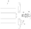
- FIG. 4 is a side cross-sectional view showing a state where a work roll is fastened to a rolling mill roll changing system according to an embodiment of the present invention.
- FIG. 5 is a perspective view showing a state where a work roll is fastened to a rolling mill roll changing system according to an embodiment of the present invention.
- FIG. 6 is a detailed perspective view of a clamping jaw according to an embodiment of the present invention.
- FIG. 7 is a continuous operation diagram in which the unloading rolls are fastened to the continuous operation rollers 2-1 and 2-2 to which the use rolls are fastened to the clamping rolls 1-1 and 1-2 according to the embodiment of the present invention.
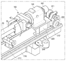
- FIG. 8 is a perspective view of a rolling mill roll replacement system in accordance with one embodiment of the present invention.
- FIGS 9 to 14 sequentially illustrate the operation of a mill roll replacement system according to one embodiment of the present invention.
- Figure 1 shows the roll configuration of a conventional Sendzimir mill.
- the Senjime rolling mill includes a pair of work rolls 10 and 20 arranged vertically and rolling the work S, and a pair of work rolls 10 and 20 arranged around the work rolls 10 and 20, 20 and a plurality of reinforcing rolls 16 to 19, 26 to 29, which support the intermediate rolls 11 to 15, 21 to 25, respectively.
- the upper inner frame 31 and the lower inner frame 32 in the rolling mill 30 can support and arrange the rolls described above.
- the upper working roll 10 is supported by two primary intermediate rolls 11 and 12, three secondary intermediate rolls 13,14 and 15 and four reinforcing rolls 16,17,18 and 19 .
- the lower work roll 20 is also supported by two primary intermediate rolls 21 and 22, three secondary intermediate rolls 23, 24 and 25 and four reinforcing rolls 26, 27, 28 and 29 Can be supported.
- the reinforcing rolls 16-19, 26-29 disposed on the outside are rotatably supported by the housing of the rolling mill 30 surrounding the outside.
- the pair of work rolls 10, 20 disposed at the center portion are worn or deformed by the operation, and therefore need to be replaced.
- the work rolls 10, 20 to be replaced can be reused through later grinding.
- the work roll has a difference in the initial roll diameter and the final roll diameter due to abrasion or the like.
- the initial roll diameter is 85 mm and the final roll diameter is about 65 mm.
- the roll axis position and the contact point between the rolls are not kept constant and the pass line which is the contact point of the upper and lower work rolls 10 and 20 through which the material S passes is managed to be constantly maintained. Therefore, there is a need for a roll changing device capable of coping with the roll position and roll change during roll changing.
- FIG. 2 shows a state in which a rolling mill according to an embodiment of the present invention is opened to replace a roll
- FIG. 3 shows a clamping unit 100 and a transfer unit 200 approaching a rolling mill according to an embodiment of the present invention.
- the rolling mill 30 is moved to the side of the rolling mill so that the clamping unit 100 can pressurize and clamp the pair of working rolls 10 and 20 Thereby opening the provided support door 40.
- the supporting door 40 is pulled by the driving portion 42 around the hinge portion 41 and rotated to open the side surface of the rolling mill.
- the clamping unit 100 advances and clamps the upper and lower work rolls 10 and 20 together
- the transporting carriage 220 of the transporting unit 200 rides on the rail 211 and moves backward to withdraw the roll.
- FIG. 3 is a plan view of a clamping unit 100 and a transfer unit 200 approaching a rolling mill 30 according to an embodiment of the present invention and Figures 4 and 5 show that the work rolls 10,
- FIG. 6 is a detailed perspective view of the clamping jaw 110.
- a rolling mill roll replacement system includes a conveying unit 200 disposed in parallel with the roll axis of the rolling mill 30, And a clamping unit 100 for extracting or inserting the clamping unit.
- the conveying unit 200 includes a conveying frame 210, a rail 211 installed on the conveying frame 210, a rack 212, a clamping unit 100 installed in the rack 212, And a drive motor 221 for providing power to the pinion 222.
- the drive motor 221 drives the pinion 222 to move along the rail 211,
- the drive motor 221 rotates the pinion 222 and the pinion 222 meshes with the rack 212 so that the forward and backward movement of the transfer bogie 220 can be performed by forward rotation or reverse rotation of the drive motor 221 .
- the transfer frame 210 may be an iron frame fixed to the ground along the axial direction of the work rolls 10,
- the clamping unit 100 is a means for pressing or pushing the outer surface of the roll and extracting or inserting it from the rolling mill.
- the clamping unit 100 mainly includes a body 101, a clamping tank 110 for pressing the rolls on the left and right, A driving unit 120 for providing power to the clamping jaw 110 via the piston rod 130 and an angular actuator 160 for rotating the clamping jaw 110 vertically or horizontally.
- the roll to be replaced may be a pair of work rolls 10, 20 spaced up and down.
- the clamping jaw 110 includes a first clamping jaw 111 and a second clamping jaw 112 each having a crossing partition wall 110A and an inclined wall 110B which are in contact with the outer surface of the roll.
- the first clamping jaw 111 and the second clamping jaw 112 can hold the work rolls 10 and 20 arranged at the top and bottom at a time.
- the first clamping jig 111 and the second clamping jig 112 are provided symmetrically so as to be opened / closed according to the operation of the piston rod 130 and the clamping driver 120.
- the clamping driver 120 may be a hydraulically operated cylinder.
- the cross barriers 110A have such a structure that the projections 110aa provided in the first clamping jaws 111 are fitted in the recesses 110ab provided in the second clamping jaws 112 when the roll is pressed.
- the protrusions 110aa and the recesses 110ab are continuously formed in the first and second clamping tanks 111 and 112, respectively, and they are engaged with each other. This allows the first and second clamping jaws 111, 112 to support the load of the roll while pressing the roll from side to side to narrow the gap.
- the cross barriers 110A are located between the upper work roll 10 and the lower work roll 20 which are vertically spaced apart from each other and the thickness of the cross barriers 110A is t and the lower inner frame 32 of the rolling mill descends
- the length is g, the following expression can be satisfied.
- the lower inner frame 32 is lowered by a certain amount in order to secure a clearance between rolls when the roll of the Senmei roll is replaced.
- the thickness between the lowering inner frame 32 and the crossing partition wall 110A will be.
- the cross barriers 110A maintain the vertical intervals of the work rolls 10 and 20 at a constant level to prevent excessive friction between the rolls and the workpiece S during roll replacement.
- the material S is positioned between the upper and lower work rolls 10 and 20.
- the crossing partition wall 110A maintains a constant gap between the upper and lower work rolls 10 and 20, (S) to pass.
- the inclined wall 110B is provided symmetrically on the upper and lower sides of the first and second clamping tanks 111 and 112 to allow the roll to slide along the oblique surface. Accordingly, the clamping jaw 110 can support the roll at three points or five points by using the cross partition 110A, the inclined wall 110B and the side wall 110C.
- the outer surface of the roll touches the left and right sidewalls 110C to support five points together with the inclined wall 110B and the intersecting ribs 110A.
- the diameter is large, three points are supported by the right and left inclined walls 110B and the crossing wall 110A.
- the clamping jaw 110 having the above-described crossing partition wall 110A and the inclined wall 110B may be applicable to rolls of various sizes.
- Figs. 1-1 and 1-2 show a continuous operation diagram in which the used roll is engaged
- Figs. 2-1 and 2-2 show a continuous operation diagram in which the unused roll is fastened
- the clamping unit 100 having the tub 110 capable of clamping rolls of different diameters in this manner is capable of simultaneously discharging and inserting the rolls regardless of the size of the working rolls.
- the clamping drive unit 120 may apply a force in a direction in which the piston rod 130 connected to both the left and right sides is narrowed or moved away.
- the coupling block 140 extends perpendicularly to the axis of the piston rod 130 and is coupled to the clamping jaw 110 so that the clamping driver 120 moves the first and second clamping jaws 111, Thereby providing power in the direction of narrowing or moving away.
- the clamping block 150 is a means for fixing the clamping unit 100 to the conveying carriage 220 and rotatably supports the clamping clamp 110 so that the clamping clamp 110 is rotated by the angular actuator 160 .
- the mill roll replacement system includes a transfer unit 200, a clamping unit 100, a storage unit 300 on which the roll is mounted, a storage unit 300 installed between the clamping unit 100 and the storage unit 300, And a control unit 500 for controlling the operation of the clamping unit 100 or the transfer unit 200 or the shift unit 400.
- the storage unit 300 includes a first storage unit 301 and a second storage unit 302 which are provided on the right and left sides of the transfer frame 210, respectively.
- the two holding tables can be used separately, and the first holding table 301 can be used in a manner of storing only the used rolls 50, and the second storing table 302 can be used in a manner of storing only the unused rolls 60.
- the shift unit 400 includes an elongate frame 420 having a seating member 430 at the end thereof and a driving unit 410 for moving the elongate frame 420 laterally of the roll.
- the shift unit 400 includes a first shift unit 401 provided in the first storage unit 301 and a second shift unit 402 provided in the second storage unit 302.
- the first shift unit 401 And the second shift unit 402 of the second storage base 302 moves the unused roll 60 of the second storage base 302 to the clamping unit 100, So that the clamping unit 100 presses the unused roll 60 and holds it.
- the control unit 500 is provided for controlling the operation of the clamping unit 100 or the transfer unit 200 or the shift unit 400.
- the control unit 500 advances the conveying truck 220 to a position near the rolling mill, (b) the clamping unit 100 presses and holds the use roll 50, (c) (D) the first shift unit 401 of the first storage table 301 moves the use roll 50 to the first storage table 301 and e)
- the clamping unit 100 moves the unused roll 60 (F) advancing the conveyance truck 220 and inserting the unused roll 60 into the rolling mill.
- FIGS 9 to 14 sequentially illustrate the operation of a mill roll replacement system according to one embodiment of the present invention.
- a method of replacing the used work roll that is, the used roll 50 with the unused roll 60 will be described with reference to this.
- the clamping unit 100 is moved forward along the rail 211 until the front end of the work roll is positioned inside the clamping tub 110 .
- the clamping unit 100 is connected to the conveying unit 200 and the driving motor 221 and the pinion 222 and the conveying frame 210 provided in the conveying carriage 220 are moved forward and backward, As shown in FIG.
- the clamping unit 100 operates the clamping driving unit 120 to close the clamping tub 110 connected to the piston rod 130, thereby firmly fixing the working roll.
- the clamping unit 100 is retracted to the initial position on the rail 211, and rotated 90 degrees by the action of the angular actuator 160 to place the work roll horizontally.
- the used work roll 50 is moved by the first shift unit 401 to the first holding table 301 in which the used roll 50 is placed and the unused roll 60 placed in the second holding table 302 is moved, Is moved centrally by the second shift unit 402 and is fixed by the clamping unit 100 and inserted into the mill 30.
- the roll changing device of the rolling mill can pressurize and move the upper roll 10 and the lower roll 20, which are vertically spaced apart, at one time, This can significantly increase the productivity of the rolling mill. Specifically, the roll replacement time is reduced by 48% compared to the conventional method, and productivity can be improved by reducing the work roll replacement time.
- the intersecting barrier ribs 110A of the first and second clamping jaws 111 and 112 are formed such that the protrusions 110aa provided on the first clamping jaw 111 when the clamping driving unit 120 is operated, (110ab) provided in the roller (112) to engage with each other, so that it is applicable to rolls of various sizes.
- the clamping unit 100 includes an angular actuator 160 for rotating the clamping jaw 110 so that the work rolls 10 and 20 vertically and vertically spaced from each other can be horizontally switched, ) Or inserting the unused roll into the rolling mill can be performed continuously.
Landscapes
- Engineering & Computer Science (AREA)
- Mechanical Engineering (AREA)
- Metal Rolling (AREA)
Abstract
본 발명에 따른 압연기 롤 교체시스템은 이송프레임과 상기 이송프레임을 따라 이동하는 이송대차를 구비하는 이송유닛; 상기 이송대차에 설치되고, 롤을 잡아주는 클램핑 조와 상기 클램핑 조를 회전시키는 앵귤러 엑츄에이터를 구비하는 클램핑유닛; 롤이 안착되는 보관대; 상기 보관대에 설치되어 상기 클램핑유닛과 상기 보관대 사이에서 롤을 운반하는 시프트유닛; 및 상기 클램핑 유닛, 상기 이송유닛, 및 상기 시프트유닛의 작동을 제어하는 제어부;를 포함한다.
Description
본 발명은 압연기에서 교체가 필요한 롤을 바꿔주기 위한 압연기 롤 교체시스템 및 그를 이용한 롤 교체방법에 관한 것이다.
압연은 금속의 소성을 이용해서 고온 또는 상온의 금속재료를 회전하는 2개의 롤 사이로 통과시켜 여러 가지 형태로 가공하는 방법이다. 이러한 압연을 수행하는 압연기 중 센지미어 압연기(Sendzimir Mill)은 소재 강도가 큰 규소강판이나 스테인레스를 냉간 압연할 때 사용된다.
센지미어 압연기는 상하로 배치된 한쌍의 작업 롤(Work Roll)과, 그 주위를 둘러싸 지지하도록 배치되는 다수의 중간 롤(IMR, Intermediate Roll)과, 다수의 보강 롤(Buck Up Roll)을 구비한다. 예를 들어 20개의 롤로 구성된 센지미어 압연기의 상측 작업 롤은 2개의 1차 중간 롤, 3개의 2차 중간 롤, 4개의 보강 롤에 의해 지지된다. 마찬가지로 하측 작업 롤도 위쪽과 대칭을 이루는 형태로 같은 수의 중간 롤들과 보강 롤들에 의해 지지된다.
이러한 압연기는 압연된 소재의 형상 및 표면 품질이 매우 중요하기 때문에 통상 하나의 코일을 작업할 때 작업 롤을 분리한 후 새로운 것으로 교체한다. 하지만 압연기의 롤을 교체하는 작업은 사용한 롤을 분리한 후 새로운 롤을 장착해야 하기 때문에 교체시간이 오래 걸리고, 이로 인해 작업 휴지시간이 길어져 생산성 저하를 초래하였다.
본 발명의 실시 예는 사용한 롤을 분리하는 작업과 새로운 롤을 장착하는 작업을 연속적으로 수행하여 롤 교체시간을 줄일 수 있는 압연기 롤 교체시스템 및 그를 이용한 롤 교체방법을 제공하고자 한다.
본 발명의 일 측면에 따르면, 이송프레임과 상기 이송프레임을 따라 이동하는 이송대차를 구비하는 이송유닛; 상기 이송대차에 설치되고, 롤을 잡아주는 클램핑 조와 상기 클램핑 조를 회전시키는 앵귤러 엑츄에이터를 구비하는 클램핑유닛; 롤이 안착되는 보관대; 상기 보관대에 설치되어 상기 클램핑유닛과 상기 보관대 사이에서 롤을 운반하는 시프트유닛; 및 상기 클램핑 유닛, 상기 이송유닛, 및 상기 시프트유닛의 작동을 제어하는 제어부;를 포함하는 압연기 롤 교체시스템이 제공될 수 있다.
상기 클램핑 조는 롤의 외면과 접하는 교차격벽과 경사벽을 포함하고, 상기 교차격벽은 롤 가압시 상기 제1 클램핑 조에 마련된 돌출부와 상기 제2 클램핑 조에 마련된 움푹부가 서로 겹쳐지는 구조를 가질 수 있다.
상하로 이격 배치되는 상부롤과 하부롤 사이에 상기 교차격벽에 위치하고, 상기 경사벽은 제1 및 제2 클램핑 조에 상하좌우 대칭으로 마련되고 롤이 빗면을 따라 미끄럼 이동하여 다양한 크기의 롤에 대응 가능하다.
상기 시프트유닛은 구동부에 의해 상기 보관대의 측방으로 이동하는 연장프레임; 및 롤이 놓여지고, 상기 연장프레임 상에 설치되는 안착부재;를 포함한다.
상기 보관대는 상기 사용 롤을 보관하는 제1 보관대와, 상기 미사용롤을 보관하는 제2 보관대를 포함하고, 상기 시프트유닛은 상기 제1 보관대에 마련되는 제1 시프트유닛과, 상기 제2 보관대에 마련되는 제2 시프트유닛을 포함한다.
본 발명의 다른 측면에 따르면, 상기 압연기 롤 교체시스템을 이용한 롤 교체방법에 있어서, (a) 상기 클램핑 조를 이용해 상기 압연기 내에 상하로 배치된 사용 롤을 클램핑하고, (b) 상기 이송대차를 상기 보관대 가까이 후퇴시키고, 상기 앵귤러 엑츄에이터가 상기 클램핑 조를 회전시키면 상기 시프트유닛은 상기 사용 롤을 상기 보관대로 옮기고, (c) 상기 시프트유닛이 상기 보관대의 미사용 롤을 상기 클램핑유닛 전방으로 옮기면 상기 클램핑유닛이 상기 미사용 롤을 클램핑하고, (d) 상기 앵귤러 엑츄에이터가 상기 미사용 롤이 상하로 배치되도록 상기 클램핑 조를 회전시키고, 상기 이송대차를 전진시켜 상기 미사용 롤을 상기 압연기에 삽입하는 과정이 순차로 수행되는 압연기 롤 교체방법이 제공될 수 있다.
상기 클램핑 조는 롤의 외면과 접하는 교차격벽과 경사벽을 포함하고, 상기 교차격벽은 롤 가압시 상기 제1 클램핑 조에 마련된 돌출부와 상기 제2 클램핑 조에 마련된 움푹부가 서로 겹쳐지는 구조를 가질 수 있다.
상하로 이격 배치되는 상부롤과 하부롤 사이에 상기 교차격벽에 위치하고, 상기 경사벽은 제1 및 제2 클램핑 조에 상하좌우 대칭으로 마련되고 롤이 빗면을 따라 미끄럼 이동하여 다양한 크기의 롤에 대응 가능하다.
상기 시프트유닛은 구동부에 의해 상기 보관대의 측방으로 이동하는 연장프레임; 및 롤이 놓여지고, 상기 연장프레임 상에 설치되는 안착부재;를 포함한다.
상기 보관대는 상기 사용 롤을 보관하는 제1 보관대와, 상기 미사용롤을 보관하는 제2 보관대를 포함하고, 상기 시프트유닛은 상기 제1 보관대에 마련되는 제1 시프트유닛과, 상기 제2 보관대에 마련되는 제2 시프트유닛을 포함할 수 있다.
본 발명의 실시 예에 따른 압연기의 롤 교체장치는 상하로 이격 배치된 상부 롤과 하부 롤을 한번에 가압하여 이동시킴으로써 압연기의 작업 롤 교체시간을 현저히 단축할 수 있고, 이를 통해 압연공장의 생산성을 현저히 높일 수 있다.
또한, 제1 및 제2 클램핑 조의 교차격벽은 클램핑 구동부 작동 시 제1 클램핑 조에 마련된 돌출부가 그와 대응되는 형상의 제2 클램핑 조에 마련된 움푹부에 끼워져 서로 맞물리는 구조를 가짐으로써 다양한 크기의 롤에 대응 가능하다.
또한, 클램핑유닛은 클램핑 조를 회전시키는 앵귤러 엑츄에이터를 더 포함하여, 상하 수직으로 이격 배치된 작업 롤을 수평으로 전환가능하므로 사용 롤을 보관대에 안치하거나 미사용롤을 압연기에 삽입하는 과정이 연속적으로 수행될 수 있다.
도 1은 통상적인 센지미어 압연기(Sendzimir mill)의 롤 구성을 나타낸다.
도 2는 롤을 교체하기 위해 본 발명의 일 실시예에 따른 압연기를 개방한 상태를 도시한다.
도 3는 본 발명의 일 실시예에 따른 압연기에 접근한 클램핑유닛과 이송유닛의 평면도이다.
도 4는 본 발명의 일 실시예에 따른 압연기 롤 교체시스템에 작업 롤이 체결된 상태를 나타내는 측단면도이다.
도 5는 본 발명의 일 실시예에 따른 압연기 롤 교체시스템에 작업 롤이 체결된 상태를 나타내는 사시도이다.
도 6는 본 발명의 일 실시예에 따른 클램핑 조의 상세 사시도이다.
도 7는 본 발명의 일 실시예에 따른 클램핑 조에 (1-1, 1-2) 사용 롤이 체결되는 연속 동작도와 (2-1, 2-2) 미사용 롤이 체결되는 연속 동작도이다.
도 8는 본 발명의 일 실시예에 따른 압연기 롤 교체시스템의 사시도이다.
도 9 내지 14는 본 발명의 일 실시예에 따른 압연기 롤 교체시스템의 작동을 순차 도시한다.
이하에서는 본 발명의 실시 예를 첨부 도면을 참조하여 상세히 설명한다. 이하의 실시 예는 본 발명이 속하는 기술분야에서 통상의 지식을 가진 자에게 본 발명의 사상을 충분히 전달하기 위해 제시하는 것이다. 본 발명은 여기서 제시한 실시 예만으로 한정되지 않고 다른 형태로 구체화될 수도 있다. 도면은 본 발명을 명확히 하기 위해 설명과 관계 없는 부분의 도시를 생략하고, 이해를 돕기 위해 구성요소의 크기를 다소 과장하여 표현할 수 있다.
도 1은 통상적인 센지미어 압연기(Sendzimir mill)의 롤 구성을 나타낸다. 도시되 바와 같이 센지미어 압연기는 상하로 배치되어 소재(S)를 압연하는 한쌍의 작업 롤(10,20)과, 작업 롤(10,20) 주위를 둘러 싸는 형태로 배치되어 작업 롤(10,20)을 지지하는 다수의 중간 롤(11~15,21~25)과 다수의 보강 롤(16~19,26~29)을 구비한다. 여기서, 압연기(30) 내부의 상부 이너 프레임(31)과 하부 이너 프레임(32)은 상술한 롤들을 지지 및 배치시킬 수 있다.
상측의 작업 롤(10)은 2개의 1차 중간 롤(11,12), 3개의 2차 중간 롤(13,14,15), 4개의 보강 롤(16,17,18,19)에 의해 지지될 수 있다. 마찬가지로 하측의 작업 롤(20)도 2개의 1차 중간 롤(21,22), 3개의 2차 중간 롤(23,24,25), 4개의 보강 롤(26,27,28,29)에 의해 지지될 수 있다. 그리고 외곽에 배치되는 보강 롤들(16~19,26~29)은 외측을 포위하는 압연기(30)의 하우징에 회전 가능하게 지지된다.
중심부에 배치되는 한쌍의 작업 롤(10,20)은 작업에 의해 마모되거나 변형되므로 교체할 필요가 있다. 교체되는 작업 롤(10,20)은 추후 연마를 통해 재 사용될 수 있다.
한편, 작업 롤은 마모 등에 의해 초기 롤경과 최종 롤경에 차이가 발생한다. 예를 들면 초기 롤경은 85mm, 최종 롤경은 65mm 정도가 되는 것이다. 롤경의 변화에 따라 롤 축 위치, 롤 간 접촉지점 등은 일정하게 유지되지 않으며, 소재(S)이 통과하는 상하 작업 롤(10,20)의 접촉점인 패스라인이 일정하게 유지되도록 관리된다. 따라서, 롤 교체시 롤의 위치 및 롤 경 변화에 대응할 수 있는 롤 교체장치를 필요로 한다.
도 2는 롤을 교체하기 위해 본 발명의 일 실시예에 따른 압연기를 개방한 상태를 도시하고, 도 3은 본 발명의 일 실시예에 따른 압연기에 접근한 클램핑유닛(100)과 이송유닛(200)의 평면도를 나타낸다.
이를 참조하면, 압연기(30)에서 작업 롤(10,20)을 교체 시 압연기(30)는 클램핑유닛(100)이 한 쌍의 작업 롤(10,20)을 가압하여 클램핑할 수 있도록 압연기 측면에 마련된 지지도어(40)를 개방한다. 지지도어(40)는 힌지부(41)를 중심으로 구동부(42)에 의해 당겨져 회전함으로써 압연기의 측면은 개방된다.
본 발명에 따른 압연기 롤 교체시스템은 사용된 작업 롤이 압연기의 푸쉬 바(push-bar)에 의해 앞으로 밀려 나온 상태에서, 클램핑유닛(100)이 전진하여 상하 작업 롤(10,20)을 함께 클램핑하여 추출하고, 이송유닛(200)의 후술할 이송대차(220)가 레일(211)을 타고 후진하여 롤을 인출한다.
도 3는 본 발명의 일 실시예에 따른 압연기(30)에 접근한 클램핑유닛(100)과 이송유닛(200)의 평면도이고, 도 4와 5는 롤 교체장치에 작업 롤(10,20)이 체결된 상태를 나타내는 측단면도와 사시도이고, 도 6는 클램핑 조(110)의 상세 사시도를 나타낸다.
도면을 참조하면, 본 발명의 일실시예에 따른 압연기 롤 교체시스템은 압연기(30)의 롤 축선과 평행하게 배치되는 이송유닛(200), 및 이송유닛(200)을 따라 진퇴하고, 압연기에서 롤을 추출하거나 삽입하는 클램핑유닛(100)을 포함한다.
도 5를 참조하면, 이송유닛(200)은 이송프레임(210), 이송프레임(210) 상에 설치되는 레일(211)과 랙(212), 클램핑유닛(100)이 설치되고 랙(212)에 치합하는 피니언(222)을 가져 레일(211) 위를 주행하는 이송대차(220), 피니언(222)에 동력을 제공하는 구동모터(221)를 포함한다. 이송대차(220)의 전진 또는 후진은, 구동모터(221)가 피니언(222)을 회전시키고 피니언(222)은 랙(212)과 맞물려 있으므로, 구동모터(221)의 정회전 또는 역회전에 의해 구현된다. 여기서 이송프레임(210)은 작업 롤(10,20)의 축방향을 따라 지면에 고정되는 철제 프레임일 수 있다.
도 5와 6을 참조하면, 클램핑유닛(100)은 롤의 외면을 가압하여 압연기에서 추출하거나 삽입하기 위한 수단으로, 크게 몸체(101)와, 좌우에서 롤을 가압하는 클램핑 조(110)와, 클램핑 조(110)에 피스톤 로드(130)를 매개로 동력을 제공하는 구동부(120)와, 클램핑 조(110)를 수직 또는 수평으로 회전시키는 앵귤러 엑츄에이터(160)를 포함한다. 이때, 교체하는 롤은 상하로 이격 배치된 한 쌍의 작업 롤(10,20)일 수 있다.
클램핑 조(110)는 롤의 외면과 접하는 교차격벽(110A)과 경사벽(110B)을 각각 구비하는 제1 클램핑 조(111)와 제2 클램핑 조(112)를 포함한다. 제1 클램핑 조(111)와 제2 클램핑 조(112)는 상하로 배치된 작업 롤(10,20)을 한번에 잡아줄 수 있다. 좌우 대칭으로 제1 클램핑 조(111)와 제2 클램핑 조(112)가 마련되어 피스톤 로드(130)와 클램핑 구동부(120)의 작동에 따라 개폐(Open/Close) 되도록 하는 것이다. 이때 클램핑 구동부(120)는 유압식으로 작동되는 실린더일 수 있다.
교차격벽(110A)은 롤 가압 시 제1 클램핑 조(111)에 마련된 돌출부(110aa)가 제2 클램핑 조(112)에 마련된 움푹부(110ab)에 끼워지는 구조를 가진다. 제1 및 제2 클램핑 조(111,112)에 각각 연속적으로 돌출부(110aa)와 움푹부(110ab)가 형성되고, 그들이 서로 맞물리게 끼워지는 것이다. 이는 제1 및 제2 클램핑 조(111,112)가 롤의 하중을 지지하면서 롤을 좌우에서 가압하며 간격을 좁힐 수 있게 한다.
교차격벽(110A)은 상하로 이격 배치되는 상부 작업 롤(10)과 하부 작업 롤(20) 사이에 위치하는데, 교차격벽(110A)의 두께를 t라고 하고 압연기의 하부 이너 프레임(32)의 하강 길이를 g라고 할 경우, 하기의 식을 만족할 수 있다.
t = g - x, (2mm <= x <= 3mm)
하부 이너 프레임(32)은 센지미어 압연기의 롤 교체 시, 롤 사이의 간격 확보를 위하여 일정량 하강(Down)되는데 이러한 하부 이너 프레임(32)의 하강 길이와 교차격벽(110A) 사이의 두께를 수식화 한 것이다. 이러한 교차격벽(110A)은 작업 롤(10,20)의 상하간격을 일정하게 유지시켜 롤 교체 시 롤과 소재(S) 간의 과도한 마찰 발생을 막는다.
한편, 압연기 내에 소재(S)이 있을 때 작업 롤을 교체해야하는 경우가 발생한다. 이 경우 상부와 하부 작업 롤(10,20) 사이에는 소재(S)가 위치하게 되는데 교차격벽(110A)는 상부와 하부 작업 롤(10,20) 간의 간격을 일정하게 유지시켜, 상하부 롤사이로 소재(S)이 지나가도록 하는 기능도 수행한다.
경사벽(110B)는 제1 및 제2 클램핑 조(111, 112)의 상하좌우에 대칭으로 마련되어 롤이 빗면을 따라 미끄럼 이동하게 한다. 이를 통해 클램핑 조(110)는 교차격벽(110A)과 경사벽(110B)과 측벽(110C)을 이용해 롤을 3점 지지 또는 5점 지지할 수 있다. 롤의 지름이 작은 경우 클램핑 조(110)가 롤을 가압하면 롤의 외면이 좌우 측벽(110C)에 닿게 되어 경사벽(110B)과 교차격벽(110A)과 함께 5점 지지를 하게 되고, 롤의 지름이 큰 경우에는 좌우 경사벽(110B)과 교차격벽(110A)으로 3점 지지하는 것이다.
도 7을 참조하면, 상술한 교차격벽(110A)과 경사벽(110B)을 구비한 클램핑 조(110)는 다양한 크기의 롤에 대응 가능할 수 있다. 도 (1-1) 및 (1-2)는 사용 롤이 체결되는 연속 동작도를 도시하고, 도 (2-1)와 도 (2-2)는 미사용 롤이 체결되는 연속 동작도를 도시하는데, 이처럼 서로 다른 직경의 롤을 클램핑할 수 있는 조(110)를 구비한 클램핑유닛(100)은 작업 롤의 크기와 관계 없이 롤 배출 및 삽입이 동시에 가능하다.
클램핑 구동부(120)는 좌우 양측에 연결된 피스톤 로드(130)가 좁혀지거나 멀어지는 방향으로 각각 힘을 가할 수 있다. 그리고 조 연결 블록(140)은 피스톤 로드(130)의 축에서 수직으로 연장되어 클램핑 조(110)와 체결되는데, 이로써 클램핑 구동부(120)는 제1 및 제2 클램핑 조(111, 112)가 서로 좁혀지거나 멀어지는 방향으로 동력을 제공하게 된다.
체결블럭(150)은 클램핑유닛(100)을 이송대차(220)에 고정 설치하기 위한 수단으로, 클램핑 조(110)를 회전 가능하게 축 지지하여 클램핑 조(110)가 앵귤러 엑츄에이터(160)에 의해 회전되게 한다.
도 8는 본 발명의 일 실시예에 따른 압연기 롤 교체시스템의 사시도이다. 이를 참조하면, 압연기 롤 교체시스템은 이송유닛(200)과, 클램핑유닛(100), 그리고 롤이 안착되는 보관대(300), 보관대(300)에 설치되어 클램핑유닛(100)과 보관대(300) 사이에서 롤을 운반하는 시프트유닛(400), 및 클램핑유닛(100) 또는 이송유닛(200) 또는 시프트유닛(400)의 작동을 제어하는 제어부(500)를 포함할 수 있다.
보관대(300)는 이송프레임(210) 좌우에 각각 마련되는 제1 보관대(301)와 제2 보관대(302)를 포함한다. 이때 두 보관대는 구분되어 사용될 수 있는데, 제1 보관대(301)는 사용 롤(50)만을 보관하고, 제2 보관대(302)는 미사용 롤(60)만을 보관하는 방식으로 이용될 수 있다.
시프트유닛(400)은 끝단부에 롤이 놓이는 안착부재(430)가 구비된 연장프레임(420)과, 연장프레임(420)을 롤의 측방으로 이동시키는 구동부(410)를 포함한다.
시프트유닛(400)은 제1 보관대(301)에 마련되는 제1 시프트유닛(401)과, 제2 보관대(302)에 마련되는 제2 시프트유닛(402)을 포함하는데, 제1 시프트유닛(401)은 사용 롤(50)을 제1 보관대(301)로 옮기고, 제2 보관대(302)의 제2 시프트유닛(402)은 제2 보관대(302)의 미사용 롤(60)을 클램핑유닛(100) 전방으로 옮겨 클램핑유닛(100)이 미사용 롤(60)을 가압하여 잡도록 한다.
제어부(500)는 클램핑유닛(100) 또는 이송유닛(200) 또는 시프트유닛(400)의 작동을 제어하기 위하여 마련된다. 압연기 롤 교체 시에 제어부(500)는, (a) 이송대차(220)를 압연기 가까이 전진시키고, (b) 클램핑유닛(100)이 사용 롤(50)을 가압하여 잡고, (c) 이송대차(220)를 제1 및 제2 보관대(300) 가까이 후퇴시키고, (d) 제1 보관대(301)의 제1 시프트유닛(401)은 사용 롤(50)을 제1 보관대(301)로 옮기고, (e) 제2 보관대(302)의 제2 시프트유닛(402)은 제2 보관대(302)의 미사용 롤(60)을 클램핑유닛(100) 전방으로 옮기면 클램핑유닛(100)이 미사용 롤(60)을 가압하여 잡고, (f) 이송대차(220)를 전진시켜 미사용 롤(60)을 압연기에 삽입하는 과정이 순차 수행하도록 제어할 수 있다.
이상으로 압연기 롤 교체시스템 및 압연기 롤 교체시스템을 이루는 각 부분들을 살펴보았다. 이들 구성들은 유기적으로 결합되어 상하로 배치된 작업 롤(Work Roll)을 각각 하나씩 인출하고 삽입하던 것을 동시에 교환할 수 있도록 하여, 생산성에 중요한 휴지시간을 단축시킨다. 센지미어 압연기로 작업된 소재(S)는 형상 및 표면 품질(조도 등)이 매우 중요하기 때문에 자주 작업 롤을 교체하는게 일반적이기 때문에 교체시간 및 그로 인한 휴지시간 단축은 생산성에 크게 영향을 미친다.
도 9 내지 14는 본 발명의 일 실시예에 따른 압연기 롤 교체시스템의 작동을 순차 도시한다. 이하에서는 이를 참조하여 사용한 작업 롤, 즉 사용 롤(50)을 미사용 롤(60)로 교체하는 방법을 설명하기로 한다.
먼저, 작업 롤을 후단의 푸쉬 바(미도시)에 의해 일정거리만큼 앞으로 밀어내면, 클램핑유닛(100)을 레일(211)을 따라 작업 롤 전단이 클램핑 조(110) 내측에 위치할 때까지 전진시킨다. 이때 클램핑유닛(100)의 전진 및 후진은 클램핑유닛(100)이 이송유닛(200)과 연결되어 있고, 이송대차(220)에 마련된 구동모터(221)와 피니언(222) 및 이송프레임(210)에 마련된 랙(212)에 의해 구현된다.
이후 클램핑유닛(100)은 클램핑 구동부(120)를 작동시켜 피스톤 로드(130)에 연결된 클램핑 조(110)를 닫아 작업 롤을 강하게 고정한다. 다음으로 클램핑유닛(100)은 레일(211)을 타고 초기위치까지 후진되고, 앵귤러 액추에이터(160)(Angular Actuator)의 작용으로 90도 회전되어 작업 롤을 수평으로 놓이게 한다.
사용된 작업 롤(50)은 인출 후 제1 시프트유닛(401)에 의해 사용 롤(50)이 안치되는 제1 보관대(301)로 이동시키고, 제2 보관대(302)에 놓여진 미사용 롤(60)은 제2 시프트유닛(402)에 의해 중앙으로 이동 및 클램핑유닛(100)에 의해 고정되어 압연기(30) 안으로 삽입된다.
다시 말해, (a) 클램핑 조(110)를 이용해 압연기(30) 내에 상하로 배치된 사용 롤(50)을 클램핑하고, (b) 이송대차(220)를 보관대(300) 가까이 후퇴시키고, 앵귤러 엑츄에이터(160)가 클램핑 조(110)를 회전시키면 시프트유닛(400)은 사용 롤(50)을 보관대(300)로 옮기고, (c) 시프트유닛(400)이 보관대(300)의 미사용 롤(60)을 클램핑유닛(100) 전방으로 옮기면 클램핑 조(110)가 미사용 롤(60)을 클램핑하고, (d) 앵귤러 엑츄에이터(160)가 미사용 롤(60)이 상하로 배치되도록 클램핑 조(110)를 회전시키고, 이송대차(220)를 전진시켜 미사용 롤(60)을 압연기(30)에 삽입하는 과정을 순차로 수행하는 것이다.
이처럼, 본 발명의 실시 예에 따른 압연기의 롤 교체장치는 상하로 이격 배치된 상부 롤(10)과 하부 롤(20)을 한번에 가압하여 이동시킴으로써 압연기의 작업 롤 교체시간을 현저히 단축할 수 있고, 이를 통해 압연공장의 생산성을 현저히 높일 수 있다. 구체적으로 롤 교체시간은 기존 방식 대비 48% 시간 감소효과가 있으며, 이에 따라 작업 롤 교체 시간감소에 의한 생산성 향상을 얻을 수 있다.
또한, 제1 및 제2 클램핑 조(111,112)의 교차격벽(110A)은 클램핑 구동부(120) 작동 시 제1 클램핑 조(111)에 마련된 돌출부(110aa)가 그와 대응되는 형상의 제2 클램핑 조(112)에 마련된 움푹부(110ab)에 끼워져 서로 맞물리는 구조를 가짐으로써 다양한 크기의 롤에 대응 가능하다.
또한, 클램핑유닛(100)은 클램핑 조(110)를 회전시키는 앵귤러 엑츄에이터(160)를 포함하여, 상하 수직으로 이격 배치된 작업 롤(10,20)을 수평으로 전환가능하므로 사용 롤을 보관대(300)에 안치하거나 미사용롤을 압연기에 삽입하는 과정이 연속적으로 수행될 수 있다.
본 발명은 첨부된 도면에 도시된 일 실시 예를 참고로 설명되었으나, 이는 예시적인 것에 불과하며, 당해 기술 분야에서 통상의 지식을 가진 자라면 이로부터 다양한 변형 및 균등한 타 실시 예가 가능하다는 점을 이해할 수 있을 것이다. 따라서 본 발명의 진정한 범위는 첨부된 청구 범위에 의해서만 정해져야 할 것이다.
Claims (8)
- 이송프레임과 상기 이송프레임을 따라 이동하는 이송대차를 구비하는 이송유닛;상기 이송대차에 설치되고, 롤을 잡아주는 클램핑 조와 상기 클램핑 조를 회전시키는 앵귤러 엑츄에이터를 구비하는 클램핑유닛;롤이 안착되는 보관대;상기 보관대에 설치되어 상기 클램핑유닛과 상기 보관대 사이에서 롤을 운반하는 시프트유닛; 및상기 클램핑 유닛, 상기 이송유닛, 및 상기 시프트유닛의 작동을 제어하는 제어부;를 포함하는 압연기 롤 교체시스템.
- 제1항에 있어서,상기 클램핑 조는상하로 이격 배치되는 상부롤과 하부롤 사이에 위치하는 교차격벽과, 상하좌우 대칭으로 마련되는 경사벽을 포함하고,다양한 크기의 롤에 대응 가능한 압연기 롤 교체시스템.
- 제1항에 있어서,상기 시프트유닛은구동부에 의해 상기 보관대의 측방으로 이동 가능한 연장프레임; 및롤이 놓여지고, 상기 연장프레임 상에 설치되는 안착부재;를 포함하는 압연기 롤 교체시스템.
- 제1항에 있어서,상기 보관대는 사용 롤을 보관하는 제1 보관대와, 미사용롤을 보관하는 제2 보관대를 포함하고,상기 시프트유닛은 상기 제1 보관대에 마련되는 제1 시프트유닛과, 상기 제2 보관대에 마련되는 제2 시프트유닛을 포함하는 압연기 롤 교체시스템.
- 제1항에 따른 압연기 롤 교체시스템을 이용한 롤 교체방법에 있어서,(a) 상기 클램핑 조를 이용해 상기 압연기 내에 상하로 배치된 사용 롤을 클램핑하고,(b) 상기 이송대차를 상기 보관대 가까이 후퇴시키고, 상기 앵귤러 엑츄에이터가 상기 클램핑 조를 회전시키면 상기 시프트유닛은 상기 사용 롤을 상기 보관대로 옮기고,(c) 상기 시프트유닛이 상기 보관대의 미사용 롤을 상기 클램핑유닛 전방으로 옮기면 상기 클램핑 조가 상기 미사용 롤을 클램핑하고,(d) 상기 앵귤러 엑츄에이터가 상기 미사용 롤이 상하로 배치되도록 상기 클램핑 조를 회전시키고, 상기 이송대차를 전진시켜 상기 미사용 롤을 상기 압연기에 삽입하는 과정이 순차로 수행되는 압연기 롤 교체방법.
- 제5항에 있어서,상기 클램핑 조는상하로 이격 배치되는 상부롤과 하부롤 사이에 위치하는 교차격벽과, 상하좌우 대칭으로 마련되는 경사벽을 포함하고,다양한 크기의 롤에 대응 가능한 압연기 롤 교체시스템.
- 제5항에 있어서,상기 시프트유닛은구동부에 의해 상기 보관대의 측방으로 이동하는 연장프레임; 및롤이 놓여지고, 상기 연장프레임 상에 설치되는 안착부재;를 포함하는 압연기 롤 교체방법.
- 제5항에 있어서,상기 보관대는 상기 사용 롤을 보관하는 제1 보관대와, 상기 미사용롤을 보관하는 제2 보관대를 포함하고,상기 시프트유닛은 상기 제1 보관대에 마련되는 제1 시프트유닛과, 상기 제2 보관대에 마련되는 제2 시프트유닛을 포함하는 압연기 롤 교체방법.
Applications Claiming Priority (2)
| Application Number | Priority Date | Filing Date | Title |
|---|---|---|---|
| KR10-2017-0109778 | 2017-08-30 | ||
| KR1020170109778A KR101990937B1 (ko) | 2017-08-30 | 2017-08-30 | 압연기 롤 교체시스템 및 그를 이용한 롤 교체방법 |
Publications (1)
| Publication Number | Publication Date |
|---|---|
| WO2019045189A1 true WO2019045189A1 (ko) | 2019-03-07 |
Family
ID=65525783
Family Applications (1)
| Application Number | Title | Priority Date | Filing Date |
|---|---|---|---|
| PCT/KR2017/014675 Ceased WO2019045189A1 (ko) | 2017-08-30 | 2017-12-14 | 압연기 롤 교체시스템 및 그를 이용한 롤 교체방법 |
Country Status (2)
| Country | Link |
|---|---|
| KR (1) | KR101990937B1 (ko) |
| WO (1) | WO2019045189A1 (ko) |
Cited By (1)
| Publication number | Priority date | Publication date | Assignee | Title |
|---|---|---|---|---|
| EP4484027A1 (fr) * | 2023-06-29 | 2025-01-01 | Fives DMS | Outil de saisie double |
Citations (5)
| Publication number | Priority date | Publication date | Assignee | Title |
|---|---|---|---|---|
| JPH10249416A (ja) * | 1997-03-07 | 1998-09-22 | Hitachi Ltd | 圧延ロール研削方法及びシステム |
| KR100803915B1 (ko) * | 2007-04-30 | 2008-02-15 | 현대제철 주식회사 | 롤 조립용 지그장치 |
| KR20100117353A (ko) * | 2009-04-24 | 2010-11-03 | 주식회사 포스코 | 롤 교체장치 |
| KR20160139698A (ko) * | 2015-05-28 | 2016-12-07 | (주)한성중공업 | 압연롤 자동화 교체장치 |
| KR101732982B1 (ko) * | 2015-12-02 | 2017-05-08 | 주식회사 포스코 | 압연기의 워크롤 교환 장치 |
-
2017
- 2017-08-30 KR KR1020170109778A patent/KR101990937B1/ko active Active
- 2017-12-14 WO PCT/KR2017/014675 patent/WO2019045189A1/ko not_active Ceased
Patent Citations (5)
| Publication number | Priority date | Publication date | Assignee | Title |
|---|---|---|---|---|
| JPH10249416A (ja) * | 1997-03-07 | 1998-09-22 | Hitachi Ltd | 圧延ロール研削方法及びシステム |
| KR100803915B1 (ko) * | 2007-04-30 | 2008-02-15 | 현대제철 주식회사 | 롤 조립용 지그장치 |
| KR20100117353A (ko) * | 2009-04-24 | 2010-11-03 | 주식회사 포스코 | 롤 교체장치 |
| KR20160139698A (ko) * | 2015-05-28 | 2016-12-07 | (주)한성중공업 | 압연롤 자동화 교체장치 |
| KR101732982B1 (ko) * | 2015-12-02 | 2017-05-08 | 주식회사 포스코 | 압연기의 워크롤 교환 장치 |
Cited By (2)
| Publication number | Priority date | Publication date | Assignee | Title |
|---|---|---|---|---|
| EP4484027A1 (fr) * | 2023-06-29 | 2025-01-01 | Fives DMS | Outil de saisie double |
| FR3150447A1 (fr) * | 2023-06-29 | 2025-01-03 | Fives Dms | Outil de saisie double |
Also Published As
| Publication number | Publication date |
|---|---|
| KR101990937B1 (ko) | 2019-06-19 |
| KR20190023667A (ko) | 2019-03-08 |
Similar Documents
| Publication | Publication Date | Title |
|---|---|---|
| JP5121721B2 (ja) | ロールを交換する方法と装置 | |
| KR101755071B1 (ko) | 롤 스탠드의 실린더 및/또는 클러스터를 교환하기 위한 장비 및 방법, 록킹 및 클램핑 시스템, 그리고 그러한 시스템을 포함하는 롤 스탠드 | |
| US4510783A (en) | Changing rolls in six-high roll stand | |
| WO2019045189A1 (ko) | 압연기 롤 교체시스템 및 그를 이용한 롤 교체방법 | |
| KR101987660B1 (ko) | 압연기의 롤 교체장치 | |
| WO2019009597A1 (ko) | 압연기 롤 교체장치 | |
| CZ20004343A3 (cs) | Zařízení k výměně nástrojů pro víceoperační obráběcí stroj | |
| CA2299280A1 (en) | Roll forming machine and method for changing side roll stands | |
| WO2020101050A1 (ko) | 압연기의 롤 교체장치 | |
| JP4159795B2 (ja) | ロール交換方法 | |
| EP1060804B1 (en) | Apparatus and method for changing piercer roll of vertical piercing mill | |
| JPWO1999019092A1 (ja) | 竪型穿孔圧延機のピアサーロール交換装置およびその交換方法 | |
| JP3779839B2 (ja) | インナースタンド式圧延機 | |
| US11173528B2 (en) | Roll changing device | |
| EP0142882B1 (en) | Straightening machine | |
| KR200465371Y1 (ko) | 금형 교환장치 | |
| JP2010042427A (ja) | タンデムプレス装置とその金型交換方法 | |
| JPH0832336B2 (ja) | 圧延機のロール組替装置 | |
| KR20030044540A (ko) | 스킨패스 밀의 워크롤 교환장치 | |
| JP2578442Y2 (ja) | プレス機械 | |
| JP2735447B2 (ja) | ローラー矯正設備 | |
| KR20240006822A (ko) | 지관 자동삽입장치 및 이의 작동방법 | |
| KR200260908Y1 (ko) | 슬라브 인출장치 | |
| KR100467039B1 (ko) | 스크랩 슬리브 코일의 슬리브 자동분리장치 | |
| RU2033869C1 (ru) | Задающее устройство трубопрокатного стана |
Legal Events
| Date | Code | Title | Description |
|---|---|---|---|
| 121 | Ep: the epo has been informed by wipo that ep was designated in this application |
Ref document number: 17923447 Country of ref document: EP Kind code of ref document: A1 |
|
| NENP | Non-entry into the national phase |
Ref country code: DE |
|
| 122 | Ep: pct application non-entry in european phase |
Ref document number: 17923447 Country of ref document: EP Kind code of ref document: A1 |